PCB manufacturing PCB manufacturing
Home > Blog

PCB Panelization Guide: V-Score, Mouse Bites and SMT Panel Design

August 28th, 2026

PCB panelization arranges multiple circuit boards within one manufacturing panel so fabrication, solder paste printing, placement, reflow, inspection and handling can process them as a stable unit. A useful panel is not simply the layout that fits the most boards. Its outline, rails, spacing, separation method, tooling features and component clearances must match the fabricator’s CAM rules, the assembly line and the final depaneling process.
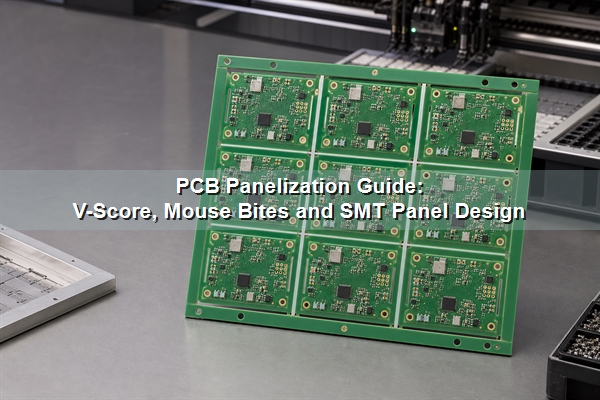
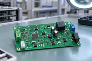
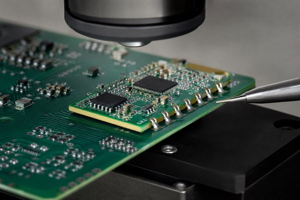
PCB panelization guide showing an SMT-ready circuit board array with rails and fiducials

What Is PCB Panelization?

PCB panelization converts one PCB design, or a controlled set of compatible designs, into a larger array that production equipment can transport and process. The finished panel normally includes the repeated board images, panel rails, separation features, global fiducials, tooling holes and identification marks. After assembly and testing, the individual boards are separated by V-scoring, routing, punching, sawing or laser cutting as appropriate.

A single PCB may be large and rigid enough to run without a delivery array, but small, narrow, irregular or thin boards often need added support. The phrase panelization construction is sometimes used for the complete arrangement of boards and temporary panel features. Practical PCB panelization guidelines must therefore define both the customer delivery panel and the fabricator-controlled production panel, which may include several delivery panels plus test coupons.

Why Is Panelizing PCB Important for Fabrication and SMT Assembly?

Panelizing PCB designs reduces repeated handling and gives conveyors, printers, placement machines and inspection systems a consistent rectangular workpiece. Several boards can pass through one stencil print, one placement program and one reflow cycle. Panel rails also protect edge components and create room for machine references that would not fit on a small finished board.

The benefit depends on the whole route. A dense array can improve laminate utilization but become too flexible under stencil pressure. A rigid array may process well yet waste material or impose excessive stress during separation. When the same supplier controls FR4 PCB fabrication and PCB assembly, CAM and SMT engineers can review the delivery panel against fabrication tolerances, stencil data, component placement and depaneling access before release.

Which PCB Panelization Methods Should You Choose?

The separation method should be chosen before the array geometry is frozen. The main PCB panelization methods have different shape, spacing, stress and edge-finish limits.

  • V-scoring: uses straight grooves from opposite sides of the panel. It is space-efficient for rectangular boards with continuous straight separation lines.
  • Tab routing: routes most of the board outline while leaving solid tabs. It supports irregular contours and allows the tabs to be cut by a router.
  • Mouse bites: add perforated holes to breakaway tabs for manual separation. A PCB panelization mouse bites pattern must match the fabricator’s drill and routing capabilities.
  • Laser depaneling: provides a narrow, non-contact cut path for suitable materials and thicknesses, but it needs specialized equipment and process review.
  • Punching or sawing: can suit stable high-volume geometries, although tooling cost or straight-line limits restrict their use.

The manufacturer should confirm channel width, residual web, tab placement and keepouts rather than relying on a universal online drawing. Material, finished thickness, copper distribution and component layout all change the result.
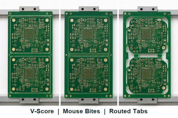
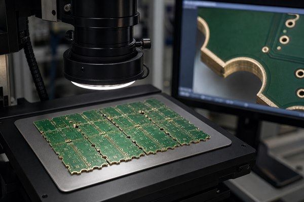
PCB panelization methods comparing V-score tab routing mouse bites and routed channels

How Do V-Score and Tab Routing Compare?

The decision starts with board geometry and permitted separation stress. V-score favors straight outlines and high panel utilization. Tab routing accepts complex shapes and controlled tab locations but consumes area for the router path.

Decision factor V-score Tab routing / mouse bites
Board outline Straight, continuous separation lines Curved or irregular outlines are possible
Board spacing Boards may share a score line Routing channel is required
Separation stress Can flex a longer board edge Localized at selected tabs
Finished edge Straight scored edge Tab witness may remain unless machine-routed flush
Component placement Needs clearance from the score and flex zone Needs clearance from tabs, router access and breakout force
Best fit Rectangular, repeatable arrays Irregular shapes and selective support points

For more detail on breakout geometry, see the related guides to mouse bites versus V-groove and V-cut PCB depaneling. The production drawing should still use the dimensions approved for the current manufacturer and equipment.

What Panel Rails, Fiducials and Tooling Holes Are Required?

Panel rails create straight conveyor edges, increase stiffness and hold temporary production features. Their width follows the printer, conveyor, fixture and depaneling setup, not a fixed internet value. Rails may also carry global fiducials, tooling holes, barcodes, coupons and orientation marks.

Global fiducials establish panel translation and rotation for vision-guided equipment. An asymmetric arrangement reduces the chance of loading the panel in the wrong orientation. Tooling holes provide mechanical registration where a fixture or process requires it. Local board fiducials may still be needed near fine-pitch BGA, QFN or other placement-critical packages.

The panel data used to manufacture an SMT stencil must use the same board step-and-repeat, origin and orientation as the placement data. A stencil generated from a single-board paste layer cannot be assumed to match a later CAM-created array unless the duplication and datum transformation are controlled.
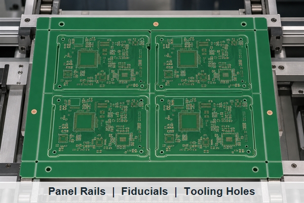
PCB panel rails with asymmetric fiducials tooling holes and SMT stencil datum features

How Should PCB Panel Size, Spacing and Component Clearance Be Set?

A reliable PCB panel design starts with the usable machine envelope, then reserves rails, separation geometry and component keepouts before calculating the array count. Filling the entire fabrication sheet first can produce a panel that cannot be printed, transported or depanelized safely.

PCB panel size is constrained by every machine that must handle the panel, including fabrication equipment, stencil printers, pick-and-place systems, reflow conveyors, AOI, test fixtures and depaneling equipment. The smallest and largest usable dimensions, conveyor direction and rail requirements should be confirmed with the actual production route.

Board-to-board spacing follows the separation tool. V-score can place straight board edges together, while routing needs a channel wide enough for the selected cutter and positional tolerance. Laser separation may use a narrower path but requires material and thermal-process review. A PCB panelization calculator can estimate how many boards fit, but it cannot see every process restriction or guarantee the lowest finished-board cost.

Component clearance must include the body, solder joints, overhang, tool envelope and expected board flex. Ceramic capacitors, BGA corners, connectors and heavy parts close to a break line deserve particular attention because depaneling strain can damage a solder joint without leaving an obvious board crack. Copper, vias and controlled-impedance structures also need clearance from score grooves, routed channels and mouse-bite holes.

When Can Different PCBs Share One Panel?

Different PCB part numbers can share a panel only when their fabrication and assembly requirements are compatible. A mixed array generally needs the same material system, layer stack, finished thickness, copper weight, surface finish, solder mask process and production quantity ratio. If one design changes, the shared panel and its assembly data may also require revision.

A homogeneous panel containing one repeated design is easier to control, inspect and replenish. A heterogeneous panel can synchronize a product set and improve material utilization, but it may create unwanted inventory if the demand ratio changes. Rotated boards can improve nesting, yet their copper distribution and component orientation should be checked for reflow, wave soldering and inspection consistency.

Rigid-flex PCB and flex PCB panelization need additional attention to stiffeners, coverlay, bend regions, tooling support and final separation. Their temporary support strategy should be reviewed as part of the material and assembly process rather than copied from a rigid FR4 grid.

What Files Define the Panelization of PCB Arrays?

The panelization of PCB arrays should be defined by one controlled data package. At minimum, identify the finished panel outline, board origins, step-and-repeat, routing or scoring paths, tabs, fiducials, tooling holes, rails and critical dimensions. The fabrication data and the drawing must agree.

  • Gerber or ODB++: copper, mask, legend, profile and panel-level production features.
  • NC drill and rout files: tooling holes, mouse bites, slots and routed channels.
  • PCB panelization drawing: overall dimensions, board arrangement, break features, datums and notes.
  • Pick-and-place data: component coordinates transformed to the panel origin and repeated orientation.
  • Paste and stencil data: the same array count and datum used by assembly.
  • Assembly drawing: panel orientation, board references, special handling and depaneling restrictions.

Do not submit a customer-created panel Gerber together with a single-board NC drill or placement file unless the relationship is explicitly controlled. Mismatched repetition counts, origins and rotations are a common source of preventable CAM and assembly questions.
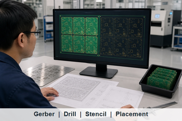
PCB panelization data review matching Gerber drill panel drawing stencil and placement origins

Which PCB Panelization Software and Tools Are Useful?

A PCB panelization tool is useful for layout exploration, but the correct choice depends on who owns the production data. PCB panelization software inside ECAD can preserve design links; CAM software can duplicate manufacturing layers, drill data and net information; a PCB panelization calculator is best treated as an early utilization estimate.

  • PCB panelization Altium workflows: Embedded Board Array and Draftsman can create repeated arrays and fabrication drawings. Searches for Altium PCB panelization and Altium Designer PCB panelization normally refer to these functions.
  • PCB panelization KiCad workflows: plugins or hierarchical layout methods can create arrays, but users should verify Gerber, drill, position and reference-designator output. The phrase KiCad PCB panelization describes the same task from the tool-first search direction.
  • Fusion 360 PCB panelization: users should confirm whether the selected Electronics/EAGLE workflow exports every required manufacturing and assembly layer for the array.
  • Free PCB panelization software: may be adequate for geometry trials, but output integrity, drill duplication, netlist consistency and revision control still require checking.
  • Manufacturer CAM: usually offers the strongest alignment with actual material utilization, routing tools, panel borders and production equipment.

Software does not know every shop-specific limit. The released files should be checked in an independent CAM viewer and approved against the manufacturer’s panel drawing.

Should You Panelize the PCB or Let the Manufacturer Do It?

Let the manufacturer create the panel when the main goal is cost-efficient fabrication and the array has no product-specific mechanical constraints. Supply clean single-board data, state whether boards must arrive as a panel or separated, identify the assembly route and approve the returned panel drawing. This lets CAM use current working-panel sizes, routing tools and process margins.

Create and control the panel yourself when the assembly fixture, test nest, barcode position, mixed-design ratio, break sequence or customer equipment requires an exact delivery format. In that case, provide both the panel data and the original single-board source, then allow a DFM review. Ownership of the layout does not remove the manufacturer’s responsibility to flag incompatible geometry.

EBest Circuit (Best Technology) lists PCB dimensions up to 610 x 610 mm, subject to stack-up, material, panel utilization and engineering review. The published PCBA process includes 3D SPI, AOI, X-ray and functional testing. Those capabilities are useful only when the approved panel, stencil, placement data and inspection program share the same revision and datum.

How Does PCB Panelization Affect Cost and Yield?

Panelization changes cost through laminate utilization, machine handling, tooling, assembly cycle time, inspection and depaneling. Increasing the number of boards per panel can reduce handling per board, but a weak or warped array can increase paste defects, placement error or breakage. The lowest material scrap is not always the lowest total cost.

Compare layouts using finished good boards per panel, expected yield and all required operations. Include routing time, score setup, tab finishing, carrier or fixture needs, stencil size, test access and the labor or machine time required to separate boards. A mixed array can reduce material waste while increasing data control and inventory risk.

What Must Be Checked Before a PCB Panel Is Approved?

Approval should freeze the panel revision that fabrication, stencil, placement, inspection and test will use. Review the panel drawing and rendered CAM output together rather than approving a dimension table in isolation.

  • Overall panel dimensions, thickness, quantity per panel and conveyor direction are stated.
  • V-score, routing channels, tabs and mouse bites match the intended depaneling process.
  • Rails, fiducials, tooling holes and orientation marks match SMT equipment and fixtures.
  • Components, copper and vias have adequate clearance from every separation feature.
  • Gerber/ODB++, NC drill, stencil, placement and assembly drawings use the same origin, rotation and revision.
  • The panel remains sufficiently rigid through printing, placement, reflow, inspection and handling.
  • Mixed designs share compatible stack-up, materials, finish and production ratio.
  • First-panel separation verifies edge quality, strain-sensitive components and fixture access before volume release.

The related PCB panelization approval guide provides a focused release-control workflow. For the present project, keep the signed panel drawing with the manufacturing package so later revisions cannot silently change the array.

PCB Panelization FAQ

What Is Meant by PCB Panelization?

What is meant by PCB panelization is the temporary grouping of multiple boards into one production unit. The boards remain connected during fabrication or assembly and are separated after the required processes are complete.

Does Every Single PCB Need a Panel?

No. A sufficiently large, rigid and machine-compatible single PCB may run without a delivery array. Small, irregular, thin or edge-sensitive boards usually benefit more from rails and repeated panel processing.

Can a PCB Panelization Calculator Produce Final Manufacturing Data?

It can estimate board count and utilization, but final data still needs routing, score, rail, tooling, fixture and equipment review. Treat the result as a layout proposal rather than automatic production approval.

Can Flex PCB Panelization Use the Same Rules as Rigid FR4?

Not automatically. Flex PCB panelization may use stiffeners, temporary carriers, tooling strips or material-specific separation methods. Bend regions, coverlay and thin-material handling require process-specific review.

Can the PCB Manufacturer Panelize Single-Board Gerbers?

Yes, and this is often the simplest route when the delivery panel has no fixed fixture constraints. State the required panel delivery, assembly process and depaneling preference, then approve the manufacturer’s drawing before production.

Conclusion

Effective PCB panelization connects board geometry with fabrication, SMT handling, separation and data control. Choose the depaneling method first, define rails and machine references, keep every production file on one datum and approve the rendered panel before release. For a DFM review of single-board or controlled panel data, contact EBest Circuit (Best Technology) at sales@bestpcbs.com.

You may also like

Certified ISO 9001 PCB Manufacturer in China with Quality Control and Traceability

August 25th, 2026

EBest Circuit is a certified ISO 9001 PCB manufacturer in China supporting bare PCB fabrication, component sourcing, PCB assembly, inspection planning, traceability, and prototype-to-volume production. Buyers can qualify the company, manufacturing scope, technical capability, and order-specific quality records through one RFQ instead of treating the certificate as the only supplier-selection criterion.

Send your released PCB data, quantities, application requirements, acceptance criteria, and required records to sales@bestpcbs.com. EBest Circuit can return a manufacturability review and quotation that identifies the proposed construction, production scope, open engineering questions, inspection plan, and shipment documents.
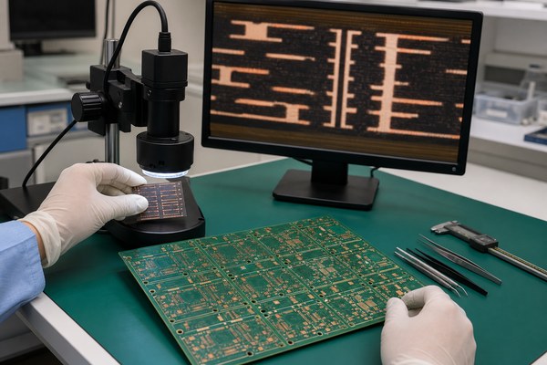
ISO 9001 PCB manufacturer, quality engineer reviewing a PCB and controlled fabrication documents

What Does ISO 9001 Mean for a PCB Manufacturer?

ISO 9001 certification confirms that the manufacturer’s quality-management system has been independently audited within the legal entity, site, and service scope shown on the certificate. For a PCB order, that system should control requirements, files, approved materials, production instructions, inspection records, nonconformities, corrective actions, and changes.

  • Customer requirements: The quotation, engineering questions, approvals, and purchase order should be reviewed before production release so the build starts from one agreed requirement set.
  • Document control: Gerber or ODB++, drill, stackup, drawing, BOM, centroid, assembly, and test files need identifiable revisions and controlled release status.
  • Supplier control: Laminates, copper-clad materials, surface-finish chemistry, and purchased components should come from evaluated sources under defined acceptance controls.
  • Process control: Fabrication and assembly steps need work instructions, trained personnel, maintained equipment, and monitoring appropriate to the product risk.
  • Corrective action: When a nonconformity occurs, the manufacturer should contain affected material, determine cause, implement action, and verify that the action works.

ISO 9001 does not define the layer count, laminate, copper thickness, via structure, impedance tolerance, surface finish, IPC class, or test limits for an individual board. These product requirements still belong in the fabrication package, purchase order, and acceptance plan. The commercial value of certification is therefore a controlled route for executing the order, not a substitute for the order itself.

How Can Buyers Verify an ISO 9001 PCB Manufacturer’s Certificate?

Verify that the certificate covers the legal entity, production site, and service scope proposed for your PCB order. Record the standard reference, certification body, accreditation information, issue date, and validity status, then match the certified name and address to the quotation and manufacturing route.

ISO 9001 PCB manufacturer, quality team checking certificate identity and scope against a PCB supplier
Certificate Field Buyer Check Risk if Unclear
Legal Entity Match the certified name to the quotation, contract, and invoice entity. A related company may be certified while the contracting entity is outside the scope.
Certified Site Confirm that the fabrication or assembly location proposed for the order is covered. A headquarters certificate may not cover a separate production site.
Service Scope Check whether the wording covers relevant manufacturing or assembly activities. The certificate may apply to sales, design, or another service rather than the quoted process.
Standard and Validity Record the full standard reference and confirm current status with the issuer or an accredited database. An obsolete, suspended, or unverifiable certificate cannot support current qualification.
Certification Body Identify the issuing body and any stated accreditation. A certificate image alone may not establish independent, accredited certification.

ISO’s certification verification guidance explains that certification is performed by independent certification bodies, not by ISO itself. If the issuer, site, or scope cannot be verified, resolve the discrepancy before approving the supplier.

What PCB Manufacturing Capabilities Does EBest Circuit Provide?

EBest Circuit provides defined process ranges for FR4 and HDI fabrication, metal-core PCBs, and ceramic PCBs. Buyers evaluating an ISO 9001 PCB manufacturer can use the table below to screen layer count, board thickness, size, trace and space, hole diameter, aspect ratio, impedance, and thermal requirements before submitting the released stackup for an order-specific feasibility review.

Specification FR4 and HDI PCB MCPCB Ceramic PCB
Maximum Layers 32 layers 10 layers Thick film: 10 layers
DCB: 2 layers
Maximum Thickness 2 layers: 6.0 mm
4 layers and above: 8.0 mm
4.0 mm Thick film: 1.5 mm
DCB: 1 layer 1.3 mm; 2 layers 1.6 mm
Maximum Board Size 610 × 610 mm
100 × 1,300 mm
610 × 1,625 mm Thick film: 200 × 200 mm
DCB: 138 × 178 mm
Minimum Trace / Space Standard: 4/4 mil
HDI: 2/2 mil
6/6 mil Thick film: 6/8 mil
DCB: 12/12 mil
Minimum Hole Diameter Standard: 0.20 mm
HDI: 0.10 mm
0.30 mm 0.10 mm
Maximum Aspect Ratio 8:1 12:1 8:1
Impedance Control >50 Ω: ±10%
≤50 Ω: ±5 Ω
Not specified Not specified
Thermal Conductivity 0.30–0.45 W/m·K Standard: 0.8–1.5 W/m·K
High: 2.0–3.0 W/m·K
Al₂O₃: ≥24 W/m·K
AlN: ≥170 W/m·K

These values describe separate process limits and must not be combined into one assumed build. Submit the stackup, material system, copper distribution, via structure, board dimensions, tolerances, finish, quantity, and acceptance criteria for a marked-up feasibility response. For bare boards, IPC printed-board standards can supply product-level criteria when the purchase documents identify the applicable standard, revision, class, and exceptions.

How Does an ISO 9001 PCB Manufacturer Manage DFM and Engineering Changes?

DFM should convert manufacturing questions into approved, traceable decisions before CAM release. Verbal assumptions and uncontrolled email attachments increase the risk of building the correct data incorrectly or building an obsolete revision correctly.

Step 1: Establish the released input set. Identify the controlling Gerber or ODB++, drill, netlist, drawing, stackup, and order revision. The manufacturer should record receipt and stop release if file names, revision marks, or dimensions conflict.

Step 2: Review manufacturability against the proposed process. Check annular rings, copper-to-edge clearances, drill relationships, solder-mask openings, controlled-impedance structures, panel rails, and any special material or finish notes. Each question should reference the affected feature and proposed disposition.

Step 3: Obtain documented buyer approval. The approved engineering response should state whether the source data changes, whether the manufacturer applies a controlled CAM adjustment, and which revision becomes production authority. Silence must not be treated as approval.

Step 4: Lock the manufacturing dataset. After approval, release one controlled dataset to production and withdraw superseded files from use. If a later change arrives, repeat impact review for tooling, work in progress, materials, assembly files, and test data.

Step 5: Verify the first output. Compare initial-lot evidence with the released drawing and agreed checks. Record discrepancies and disposition before the same process is used for repeat orders or higher volume.

An ISO 9001 PCB manufacturer should retain the approved engineering response with the released production data so later lots can be checked against the same decision history.

How Does an ISO 9001 PCB Manufacturer Control PCB Quality During Production?

PCB quality control must connect the released data to material acceptance, process checks, product inspection, electrical verification, and shipment release. The RFQ should identify which controls are standard for the proposed route and which order-specific inspections or reports need additional planning.

  • Incoming control: Match laminates, copper-clad materials, solder mask, surface-finish inputs, and purchased components to approved specifications or alternatives before use.
  • CAM and process release: Release one approved dataset, stackup, tooling package, and traveler after engineering questions are closed.
  • In-process verification: Define the measurements or coupons used to monitor dimensions, drilling, plating, registration, solder mask, controlled impedance, and other order-critical features.
  • Bare-board inspection and test: State visual and dimensional criteria, electrical-test coverage, sampling, measurement locations, limits, and required report identity.
  • Assembly controls: When PCBA is included, identify incoming component checks, solder-paste inspection, AOI, X-ray, programming, or functional test only where the design and acceptance plan require them.
  • Release and change control: Link accepted lots and shipment documents to the approved revision, then require authorization for changes identified in the purchase agreement.

Electrical test confirms conductor-network continuity against the design data but does not replace dimensional, material, workmanship, or assembly checks. The inspection plan should therefore identify the risk addressed by each method and the evidence used for lot release.

How Does ISO 9001 Improve PCB Traceability and Production Consistency?

A controlled traceability plan connects the released revision, approved material, production route, inspection results, and shipped lot. Define the identification depth during quotation so the prototype records can become the controlled baseline for pilot and volume production.

ISO 9001 PCB manufacturer, PCB lots moving through AOI inspection and traceability record review
Order Stage Control Objective Expected Output
Prototype Confirm design feasibility, manufacturing assumptions, and inspection access. Resolved engineering questions, released files, and documented build observations
Pilot or Low Volume Verify repeatability, approved materials, process settings, and record completeness. Stable route, first-article results, controlled deviations, and production-ready documentation
Volume Production Maintain the released baseline while monitoring lots, changes, and nonconformities. Lot-linked inspection, test, release, and shipment records at the agreed level

Traceability depth should match the product and contractual risk. A commercial prototype may need basic lot and revision identification, while a regulated or high-reliability program may require material batches, process route, operator or equipment records, inspection results, deviations, and shipment identity. Ask the supplier to demonstrate how a reported defect would be traced to the affected lot and released data.

What Quality Documents Can You Request From an ISO 9001 PCB Manufacturer?

Request the records needed to approve the lot, investigate a failure, or demonstrate compliance with the purchase requirements. Each document should identify the order or lot, applicable revision, test or inspection method, result, and acceptance basis.

  • Certificate of conformance: Identify the purchase order, part number, revision, shipment lot, and requirement set covered by the declaration.
  • Electrical-test record: Define test coverage, method, netlist identity, result, and board or lot relationship for opens-and-shorts verification.
  • Visual and dimensional report: State the inspected drawing features, sampling, measured values, workmanship criteria, and acceptance limits.
  • Material evidence: Request laminate, copper, finish, or other material certificates only where material identity is contractually controlled.
  • Microsection or impedance report: When required, identify coupon or board location, measured features, target, tolerance, frequency, and acceptance result.
  • PCBA inspection or test record: For assembly orders, define applicable AOI, X-ray, programming, functional test, fixture, firmware, test limits, and result format.

The certificate of conformance should identify the order or lot and the applicable requirement set. If raw measurement data, material evidence or inspection images are required, include them in the RFQ so the supplier can plan record generation and retention.

How Much Does It Cost to Work With an ISO 9001 PCB Manufacturer?

ISO 9001 certification is not a standalone line-item price; cost and lead time are driven by the board, order scope and evidence package operated within the QMS. Incomplete or conflicting inputs cause quote revisions because the manufacturer cannot select a stable process and inspection plan.

Cost Driver Commercial Impact RFQ Input
Board Construction Layer count, material, copper, via structure, finish, and tolerances determine process steps and yield margin. Released stackup, fabrication drawing, and data package
Order Quantity Tooling, engineering, and setup are distributed differently across prototype and production quantities. Prototype, pilot, and forecast quantities
Inspection and Test Coupons, microsections, impedance, special sampling, fixtures, and reports add planned work. Method, frequency, limits, and required records
Documentation Customer-specific certificates, raw data, retention, and approval packages require preparation and review. Shipment-document checklist and retention period
Components and Assembly Availability, approved alternatives, package types, programming, and functional test affect the PCBA route. BOM, CPL, drawings, substitution rules, and test package
Schedule Material procurement, engineering closure, fabrication, sourcing, assembly, inspection, and transport have separate durations. Required delivery date and priorities

Compare quotations only after confirming that suppliers priced the same specifications, quantities, inspection scope, documentation, and delivery point. A lower quote based on missing records or an unapproved material assumption is not the same offer.

An ISO 9001 PCB manufacturer can quote more accurately when technical requirements and shipment records are defined before engineering review rather than added after production planning.

Why Choose EBest Circuit as Your ISO 9001 PCB Manufacturer in China?

EBest Circuit combines an ISO 9001:2015-certified quality system with PCB engineering, fabrication, component sourcing, assembly, and prototype-to-volume support in China. The advantage is a single manufacturing response that connects technical feasibility, production scope, quality records, and commercial quotation to the same released project.

  • Verified quality-system foundation: Buyers can review EBest Circuit’s ISO 9001:2015 certificate together with the legal entity, site, and service scope used for the order.
  • Defined fabrication ranges: The current matrix covers FR4 and HDI fabrication, metal-core PCBs, and ceramic PCBs, including board size, thickness, trace and space, hole, aspect-ratio, impedance, and thermal limits that can be checked against the released design.
  • One-stop PCB and PCBA scope: PCB design support, prototyping, fabrication, component sourcing, assembly, inspection planning, and shipment documentation can be coordinated through one supplier response.
  • Controlled DFM and release: Engineering questions, proposed manufacturing adjustments, approved revisions, and superseded data can be resolved before production release.
  • Prototype-to-volume continuity: Material, process, inspection, traceability, and document requirements can be identified during prototyping and retained as quantities increase.
  • Order-specific evidence: Certificates, inspection results, electrical-test records, material evidence, and PCBA test records can be quoted according to the actual acceptance package rather than assumed after shipment.

Request EBest Circuit’s current ISO 9001:2015 certificate together with a marked-up stackup, manufacturing route, inspection plan, traceability fields, and deliverable list. This gives engineering, procurement, and quality teams one comparable package for supplier approval and quotation review.

What Files Should You Send to an ISO 9001 PCB Manufacturer?

Send one revision-aligned package that defines the product, quantity, acceptance criteria and required deliverables. The manufacturer can then return specific engineering questions and a quote based on an identifiable scope.

  • Bare PCB: Gerber or ODB++, NC drill, netlist where available, fabrication drawing, stackup, controlled-impedance information, and panel requirements.
  • Optional assembly scope: If PCBA is included, add the BOM with approved manufacturer part numbers, centroid or pick-and-place data, assembly drawings, polarity notes, and special handling requirements.
  • Commercial: Prototype and production quantities, delivery destination, required date, and any forecast relevant to material planning.
  • Quality: Applicable standards and class, inspection and test methods, sampling or full-test requirements, traceability level, and deviation-approval route.
  • Deliverables: Certificate of conformance, test report, inspection data, material evidence, or other records required with the shipment.

If one item is not finalized, mark it as an open decision rather than leaving the supplier to infer it. The quotation should identify the assumption, its cost or schedule effect, and the approval needed before release.

FAQs About ISO 9001 PCB Manufacturers

Q1: Is ISO 9001 certification mandatory for every PCB purchase?

A1: Certification is required only when the contract, market, risk controls, or approved-supplier policy calls for it. When ISO 9001 is a sourcing requirement, identify the acceptable standard reference, legal entity, production site, service scope, and verification evidence before requesting or approving a quotation.

Q2: Can an ISO 9001 PCB manufacturer provide PCB assembly services?

A2: PCB assembly can be included when the supplier’s controlled scope supports the required PCBA processes. Confirm component sourcing, approved alternatives, workmanship criteria, inspection, programming, functional testing, traceability, and shipment records so the assembly quotation covers the complete acceptance package.

Q3: Does one ISO 9001 certificate cover every branch or factory?

A3: Coverage is limited to the entities and sites identified by the certificate and its scope. If quotation, fabrication, assembly, inspection, or shipment involves another location, request written confirmation of that site’s role, quality-system coverage, transferred requirements, and retained records before supplier approval.

Q4: Does ISO 9001 guarantee defect-free PCBs?

A4: ISO 9001 does not guarantee a defect-free PCB. Product conformity still depends on complete design inputs, capable manufacturing processes, appropriate inspection and testing, clear acceptance limits, and effective containment and corrective action when a nonconformity is found.

Q5: What certifications may matter in addition to ISO 9001?

A5: Additional credentials must match the market, product, and contract. Buyers may evaluate IATF 16949 for automotive supply chains, ISO 13485 for medical-device quality systems, AS9100D for aerospace quality management, UL recognition, RoHS, or REACH evidence where applicable. Verify the entity, site, scope, validity, and order relevance of each item.

Q6: Can the manufacturer substitute an equivalent laminate?

A6: A laminate substitution is acceptable only when the released requirements or buyer approval route permits it. The supplier should identify the proposed material, property comparison, stackup effect, impedance impact, availability, and approval status before purchasing or releasing the alternative to production.

Q7: How often should a supplier’s ISO 9001 certificate be rechecked?

A7: Recheck the certificate whenever its identity or validity may affect supplier approval. Minimum triggers include initial qualification, approaching expiry, a legal-entity or site change, a revised service scope, and the periodic interval defined by the approved-supplier program. Record the certificate identity, source, verification date, and reviewer.

Q8: Does an ISO 9001-certified supplier still need an initial-lot review?

A8: An initial-lot review remains necessary when the drawing, product risk, or buyer procedure requires it. The review checks whether the approved data, material, process route, inspection plan, and records produce an acceptable board before repeat orders or a higher-volume release.

Q9: Can a certificate of conformance replace detailed test reports?

A9: A certificate of conformance is sufficient only when the purchase agreement accepts it as the complete release evidence. If measured results, raw data, inspection images, impedance reports, or material certificates are required, list each document separately in the RFQ, quotation, and shipment-document checklist.

Q10: Who should approve a PCB manufacturing deviation?

A10: The buyer representative named by the contract or change-control procedure must approve the deviation. The documented disposition should identify the affected requirement, part and revision, quantity, lot, temporary or permanent status, acceptance rationale, expiry or review point, and required follow-up action.

Conclusion

EBest Circuit offers buyers a certified PCB manufacturing partner in China with defined process ranges for FR4 and HDI fabrication, metal-core PCBs, and ceramic PCBs, plus PCBA services, controlled engineering release, traceability, and order-specific records. The RFQ should connect the applicable process range to the exact board construction, quantities, acceptance criteria, changes, and evidence required for the project.

Send your Gerber or ODB++ package, drawing, stackup, BOM if assembly is required, quantities, acceptance criteria, and record list to sales@bestpcbs.com. Ask EBest Circuit for a marked-up manufacturing response, applicable certificate, inspection plan, and quotation tied to the released PCB or PCBA requirements.
You may also like

Capacitive Touch PCB Design and Manufacturing

August 24th, 2026

A capacitive touch PCB turns copper electrodes into buttons, sliders, wheels, touchpads or proximity sensors by measuring a change in capacitance. Reliable operation depends on the complete sensing stack, not only the copper pattern, so the PCB, overlay, adhesive, enclosure, controller settings and validation plan must be developed together.

EBest Circuit supports PCB design review, prototyping, component sourcing, fabrication and assembly for touch-control projects. Reviewing the electrode layout alongside the mechanical stack and test plan can uncover conflicts before they lead to enclosure rework or another prototype spin.

capacitive touch PCB, rigid touch electrode board with flex tail and clear overlay on an engineering bench

Are you worried about capacitive touch PCB performance after final assembly?

  • Will the buttons still respond after the final glass or plastic overlay is installed?
  • Could a charger, motor, display or wet surface cause false touches in the finished product?
  • Will prototype tuning remain stable after adhesive, enclosure and production tolerances are introduced?

Drawing on more than 20 years of PCB and PCBA experience, EBest Circuit provides one-stop support by reviewing the sensor board, mechanical stack and production package as one release set.

  • Mechanical-stack review: Align electrode geometry with the actual overlay, adhesive and enclosure so sensitivity is assessed in the finished construction.
  • Layout and noise review: Check sensor routes, nearby switching nets, ground structures and shielding against the selected touch controller guidance.
  • Prototype-to-production control: Freeze the approved PCB, overlay, firmware and test revision so later builds can be compared against the same baseline.

Ready to start your capacitive touch PCB project? Contact sales@bestpcbs.com to get a quote for your project.

What Is a Capacitive Touch PCB and When Should You Use It?

A capacitive touch board is appropriate when a product needs a sealed or low-wear interface and its enclosure can provide a controlled dielectric path between the user’s finger and the sensor electrode. Typical formats include buttons, sliders, wheels, touchpads and proximity inputs. A different input method may be safer behind a thick conductive cover, under uncontrolled liquid exposure or with gloves that the selected controller cannot reliably detect.

The sensor controller repeatedly measures the electrode’s baseline capacitance. A finger changes the electric field and produces a measurable delta. In self-capacitance sensing, one electrode is measured relative to its surroundings; in mutual-capacitance sensing, the controller measures coupling between transmit and receive electrodes. The controller architecture determines electrode topology, routing rules, scan method and tuning limits, so its reference design must be selected before the sensor layout is frozen.

  • Use touch buttons: Choose individual electrodes when the interface needs discrete commands and clear activation zones.
  • Use sliders or wheels: Choose segmented electrodes when firmware must estimate position across adjacent channels.
  • Use proximity sensing: Choose a suitable controller and larger sensing field when detection must occur before physical contact.

Which Capacitive Touch PCB Structure Fits Your Product?

Select the sensor PCB construction by the mechanical path between the electrode and the touch surface. Rigid FR-4 suits supported flat panels, flex suits curved or tightly constrained interfaces, and rigid-flex connects fixed sensor and electronics zones through an integral flexible section. Whether the sensor is integrated with or separated from the main controller is a second architecture decision, not a PCB construction category.

Make this choice before layout freeze: construction changes the sensing distance, bend and registration controls, interconnection method and assembly checks.

Sensor PCB Construction Best Fit Main Constraint Verification Focus
Rigid FR-4 sensor PCB Flat, mechanically supported control panels Board-to-overlay spacing, panel flatness and enclosure support Overlay stack, dimensional registration and assembled sensitivity
Flexible sensor circuit Curved surfaces, thin interfaces or electrodes remote from the controller Static or dynamic bend definition, coverlay and stiffener transition Installed shape, bend condition, overlay stack and assembly variation
Rigid-flex sensor assembly Fixed sensor and electronics zones requiring a permanent folded interconnect Rigid-flex stack-up, transition geometry and installation sequence Transition integrity, final folded geometry, overlay registration and assembled response

Choose the PCB construction first, then choose the integration architecture. A separate sensor daughterboard can use rigid, flex or rigid-flex construction; select it when serviceability, panel replacement or separation from a noisy main board justifies an added connector or cable. Verify the resulting parasitic capacitance, ground-reference interaction, mechanical alignment and complete-system tuning.

If the sensor remains flat and the interconnect is short, rigid FR-4 normally provides simpler dimensional control. Use flex or rigid-flex when following a curved housing, reducing an air gap or relocating electronics provides enough benefit to justify additional bend, transition and assembly controls.

How Should a Capacitive Touch Button PCB Electrode Be Designed?

A touch electrode should cover the intended activation area without creating excessive baseline capacitance or overlap with adjacent sensors. Use the selected controller’s design guide as the geometry source, then verify the released pattern through the final overlay.

  • Activation footprint: Map the visible icon and expected finger contact area to the electrode so the intended button produces a clear response without extending into an adjacent activation zone.
  • Pattern topology: Use a solid or vendor-approved hatched region for a button and interleaved segments for a slider or wheel. Copying a button pad into a position sensor prevents the controller from resolving movement correctly.
  • Trace exit: Route the sensor connection directly away from the pad, avoid wrapping it around neighboring electrodes and limit parallel exposure to switching nets. Treat the trace as part of the sensing capacitance, not as an ordinary digital connection.
  • Channel consistency: Keep comparable buttons geometrically consistent unless the tuning plan explicitly compensates for different overlays, nearby metal or enclosure conditions. Unplanned differences can create unequal thresholds and user feel.
  • Edge clearance: Check bezels, fasteners, displays, conductive coatings and chassis parts near every pad because they can redirect the field or raise baseline capacitance. Review the worst mechanical tolerance, not only nominal CAD alignment.
  • Release evidence: Put electrodes, keep-outs, hatch patterns and sensor routes in controlled fabrication data. Approve the design only after the smallest and largest permitted pad/overlay conditions meet touch-delta, noise-margin and adjacent-channel criteria in the assembled enclosure.

How Do Overlay Material, Adhesive and Air Gaps Change Touch Sensitivity?

The overlay stack controls how strongly the finger couples to the electrode: greater distance and unintended air gaps usually weaken the touch signal, while dielectric material and consistent bonding determine how repeatable that coupling remains. Treat the complete stack as a sensor-design input before freezing the PCB layout.

  • Material definition: Identify glass, polycarbonate, acrylic, printed film or coating by the released material specification because dielectric behavior and rigidity affect coupling differently.
  • Total sensing distance: Control overlay, adhesive, paint and coating thickness together. A nominal cover dimension alone misses the layers that separate the finger from the electrode.
  • Bonded interface: Specify adhesive type, bonded area, compression and permitted voids. An uncontrolled air gap can weaken or vary the signal even when the PCB and cover meet their individual dimensions.
  • Mechanical features: Review molded ribs, local curvature, printed graphics and registration tolerance over each pad. Metal-filled ink or uneven geometry can change the field locally and make channels behave differently.
  • Verification extremes: Use the controller vendor’s overlay guidance as the starting boundary, then test the thickest permitted stack, worst registration and relevant temperature/humidity conditions on representative assemblies.

How Should Capacitive Touch Sensor PCB Layout Control Noise and Parasitics?

Layout on a capacitive touch PCB must keep sensor capacitance stable and distinguishable from power, display, communication and switching noise. Short sensor routes, controlled separation and a controller-specific guard or shield strategy reduce coupling, but indiscriminate ground copper near or beneath the electrode can increase parasitic capacitance and reduce sensitivity.

  • Sensor routing: Route each sensor trace directly to the controller, avoid long parallel exposure to clocks or switching nodes and treat its length as part of channel capacitance.
  • Aggressor separation: Keep DC/DC converters, display clocks, high-current LED drivers and motor switching away from the sensor region where mechanics permit. If crossing is unavoidable, follow the controller guidance and avoid a long shared path.
  • Ground placement: Select clearance, hatched ground, shield electrodes or driven shielding from controller documentation and measured SNR. A copied solid-ground rule can raise parasitic capacitance and reduce touch margin.
  • Guard structures: Add a guard ring only when it provides the intended discharge or field boundary without consuming unacceptable channel margin; verify the result on the assembled stack.
  • Power integrity: Apply the controller’s required decoupling and filtering, then measure channel noise with the actual charger, display and actuators operating.
  • Layer and review record: Minimize vias, document layer changes and close the layout review with a channel map covering route length, nearby aggressors, shield/ground condition, mechanical stack and validation mode.

How Can a Capacitive Touch PCB Resist Water, EMI and False Touches?

False-touch resistance comes from combining electrode topology, shielding, clean power, controller algorithms and product-level validation. No single copper feature proves water or EMI immunity, and a design that works on a dry bench may fail when a wet film bridges neighboring electrodes or a switching load shifts the baseline.

  • Liquid condition: Specify droplets, wet fingers, cleaning liquid, condensation and continuous flow separately. A water film can bridge electrodes, so dry-bench operation does not predict every exposure mode.
  • Detection architecture: Evaluate mutual-capacitance sensing, shield electrodes, guard arrangements or firmware discrimination against the selected controller. Approve the option only when it preserves intended-touch margin as well as rejecting the defined liquid condition.
  • Noise states: Operate chargers, displays, radios, relays, motors and converters during touch testing. Conducted or radiated interference can resemble a touch signal even when isolated channel data looks clean.
  • False-outcome record: Log missed touches, false activations, neighboring-button activation and recovery after the disturbance. A pass/fail result without the failure type does not support tuning or root-cause analysis.
  • ESD path: Review the overlay edge, enclosure, chassis and PCB protection path as one system. Protection must divert discharge energy from sensor/controller nodes without adding capacitance that destroys sensing margin.

What Must Be Frozen Before a Capacitive Touch PCB Prototype?

A useful prototype must freeze the sensor electronics, mechanical stack and firmware baseline together. If the PCB is tested with a temporary overlay or different adhesive, its behavior cannot reliably predict the finished product.

  • Electronics identity: Freeze the controller, BOM, PCB stack-up, copper/solder-mask layers and firmware revision. A component or firmware change can shift baseline, filtering or channel behavior.
  • Representative mechanics: Use the production-intent overlay, adhesive, printed graphics, enclosure features, connector/cable and nearby metal parts. Temporary covers or hand-held spacing do not represent the released field path.
  • Raw-data access: Provide a debug method that exposes baseline, touch delta, noise or controller diagnostics. A binary button indication alone cannot show whether margin is shrinking.
  • Sample variation: Include assemblies across permitted PCB, overlay, adhesive and registration tolerances rather than tuning one hand-selected unit.
  • Controlled options: Populate alternate tuning footprints only when the evaluation plan defines the option, measured variable and selection criterion; uncontrolled variants make results ambiguous.
  • Revision record: Bind every measurement to PCB, BOM, firmware, overlay and enclosure revisions plus power state and test mode so the result can be reproduced.

How Are Capacitive Touch PCBs Manufactured and Assembled?

Manufacturing must preserve the approved electrode geometry, dielectric stack, cleanliness and assembly registration while keeping the electronics build traceable. Bare-board electrical testing can confirm continuity and isolation, but only an assembled functional test can show whether the touch system responds correctly through the final overlay.

  1. Release controlled production data: Confirm Gerber or ODB++, NC drill, stack-up, electrode layer, solder-mask requirements, BOM, CPL, assembly drawings and revision identity. Misinterpreting the controlled copper source can create an electrode-geometry defect that survives basic continuity testing.
  2. Review manufacturability and panel handling: Check electrode clearances, flex transitions where applicable, fiducials, tooling, breakaway features and the effect of rails or tabs on the sensor area. Record the approved conditions in the production handoff; uncontrolled panel features can disturb the sensing field or damage sensitive geometry during handling.
  3. Fabricate and electrically inspect the bare board: Image, etch, laminate, drill, plate, apply solder mask and finish according to the released construction. Electrical test verifies opens and shorts; dimensional and visual inspection confirms the electrode artwork, registration and surface condition before assembly.
  4. Control components and substitutions: Match the touch controller, passives, connectors and protection components to the approved BOM. Any proposed substitute must be reviewed for pinout, capacitance, leakage, package, firmware support and supply-noise behavior so a mismatch does not create unstable sensing after release.
  5. Assemble the electronics: Print solder paste, place components and run the approved reflow process while protecting exposed or overlay-facing sensor surfaces from residues and mechanical damage. Inspection confirms polarity, placement and visible joints; hidden terminations require the inspection method defined for that package.
  6. Join the mechanical sensing stack: Align the PCB or flex electrode with the overlay, adhesive and enclosure using the approved drawing or fixture. Voids, contamination, skew and uneven compression create a functional failure risk and are recorded as defects because they can change coupling even when the electronics are correct.
  7. Program, tune and functionally verify: Load the controlled firmware, apply the intended calibration procedure and test every input through the assembled overlay. Release evidence should identify unit, hardware revision, firmware, test conditions and pass/fail criteria so any false or missed detection failure blocks release.
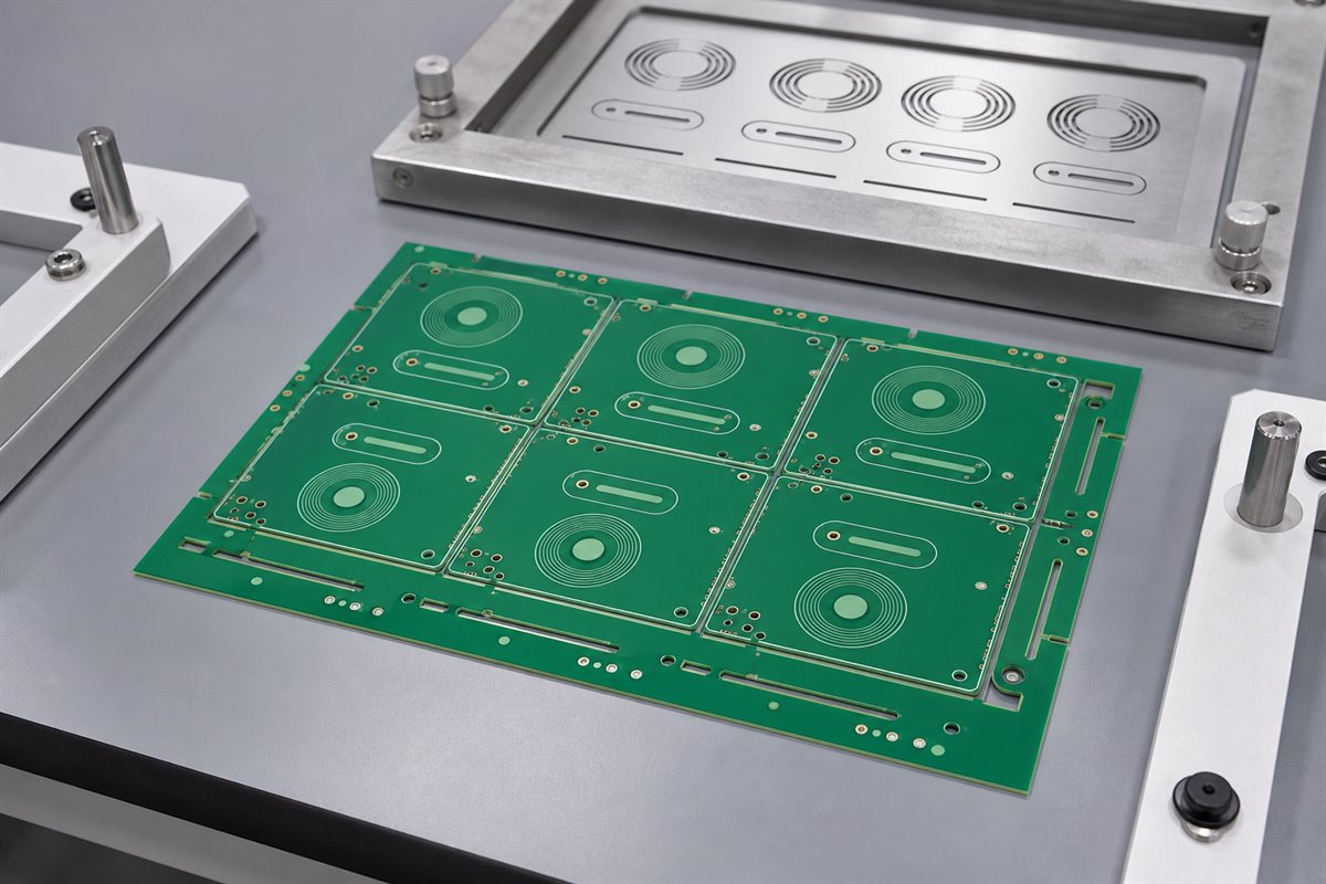
capacitive touch PCB, panelized touch sensor boards beside production tooling

This sequence separates four different proofs: artwork and construction inspection, bare-board electrical test, assembly inspection and functional touch verification. A purchasing specification should name which records are required instead of treating one inspection result as proof of the entire system.

How Should Capacitive Touch PCB Testing and Tuning Be Planned?

Testing should measure touch separation from noise across real mechanical, electrical and environmental variation. A finger demonstration on one open board is only a bring-up check; production release needs controlled samples, repeatable stimuli, recorded controller data and acceptance criteria linked to the intended product.

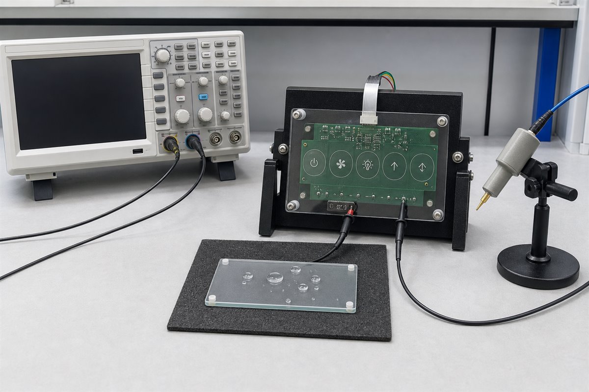
capacitive touch PCB, touch control board in a laboratory fixture with oscilloscope probes and a wet-overlay test coupon
  • Baseline and touch margin: Record baseline capacitance or the controller’s equivalent raw value, touch delta, noise and neighboring-channel response. Set thresholds only after the worst measured separation is understood.
  • Engineering tuning: Adjust thresholds, filters, scan timing and shield settings within the controller’s supported range, then retain the raw before/after data and firmware identity.
  • Mechanical variation: Repeat measurements across permitted overlay, adhesive and registration tolerances. A tuning value derived from one nominal assembly cannot prove production margin.
  • System disturbance: Exercise charger, display, radio, motor and converter states on the complete product and record both false and missed detections by channel.
  • Environmental conditions: Apply specified dry-finger, glove, liquid, temperature or humidity conditions with stabilization and recovery criteria defined in the test plan.
  • Production functional test: Use a controlled fixture or actuation method to check every channel and log unit identity, hardware revision, firmware, test condition and result.

Release only when the recorded sample range, assembled stack, test configuration, acceptance thresholds and exceptions provide a reproducible baseline for later lots or field-return comparison.

Where Are Capacitive Touch PCBs Used in Medical, Aerospace and Industrial Products?

Capacitive touch interfaces can serve sealed control surfaces in medical, aerospace and industrial products, but each application changes the failure consequences and verification burden. The examples below are design-review scenarios, not claims about completed EBest Circuit customer programs.

  • Medical control-panel example: A device interface may need cleaning-fluid tolerance, clear feedback and controlled behavior with approved gloves. Review the overlay chemistry, liquid exposure, alarm-related command risk, usability validation and the quality-system requirements assigned to that product.
  • Aerospace interface example: A cabin or equipment-panel control may face vibration, temperature variation, ESD and electromagnetic disturbances. Confirm whether touch input is suitable for the command criticality and specify tactile, visual or audible feedback plus a safe response to ambiguous activation.
  • Industrial HMI example: A machine panel may encounter wet gloves, oil, metal enclosures, inverters and motor noise. Separate touch electronics from switching nodes where practical, review grounding at system level and test during the machine’s highest-disturbance operating states.

Certifications held by a supplier do not automatically certify a board or finished device. The order must identify its applicable quality plan, documentation, inspection, traceability and product-level compliance responsibilities before production release.

Why Choose EBest Circuit for Capacitive Touch PCB Projects?

EBest Circuit can support the connected tasks that move a touch-control design from released files to verified assemblies. PCB review, prototyping, sourcing, fabrication and assembly stay tied to the same product definition and revision.

  • Design review: Identify electrode, routing and mechanical-stack questions before they become prototype respins.
  • Prototype support: Build controlled samples that let the project compare tuning changes against known hardware revisions.
  • Rigid and flex options: Align the sensor construction with flat, curved or space-constrained product mechanics to avoid unnecessary interconnects.
  • Component sourcing: Keep touch controllers, protection parts and approved alternates aligned with the released BOM.
  • PCB assembly: Reduce handoff gaps between bare-board fabrication, component placement and functional test preparation.
  • Production continuity: Keep approved files and revision identity controlled when a validated prototype moves toward repeat builds.

What Files Are Needed for a Capacitive Touch PCB Quote?

A useful quotation needs both standard PCB/PCBA production data and the mechanical sensing-stack information that changes touch behavior. Sending only a schematic or board image leaves electrode construction, assembly scope and test responsibility unresolved.

  • PCB fabrication: Gerber or ODB++, NC drill, stack-up, board outline, copper requirements, surface finish and fabrication notes.
  • Assembly: BOM with manufacturer part numbers, CPL/pick-and-place file, assembly drawings, approved substitutions and programming instructions.
  • Touch mechanics: Electrode drawing, overlay material/thickness/tolerance, adhesive stack, printed coating and enclosure or bezel drawing.
  • Functional context: Touch-controller part number, firmware/tuning ownership, input types, expected gloves or liquid exposure and interface feedback.
  • Verification: Required inspections, electrical test, functional test method, acceptance criteria, records and traceability level.
  • Commercial scope: Prototype and production quantities, delivery destination, packaging needs and controlled revision.

When functional test development is requested, also provide a known-good unit or an approved behavior specification. The test team then has a measurable release target instead of an unspecified instruction to “test the touch buttons.”

FAQs About Capacitive Touch PCB Design and Manufacturing

Q1: Can a capacitive touch electrode be placed on an inner PCB layer?

A1: It may be possible when the added dielectric distance still leaves verified sensing margin. Use the controller guidance to evaluate the layer stack, copper above the pad and overlay distance, then compare raw channel data with the outer-layer option before release.

Q2: Should solder mask be opened over a touch electrode?

A2: Usually not when the electrode senses through a cover and does not need electrical contact. Keeping the mask can protect the copper, but the released mask thickness and any opening must match the tested construction instead of being changed as a cosmetic fabrication decision.

Q3: Can an LED backlight be placed behind a capacitive touch button?

A3: Yes, if the optical opening, LED drive and electrode pattern are evaluated together. The cutout can reduce sensing area, while LED switching can inject noise. Measure the channel with the backlight off, dimmed and at maximum intended activity.

Q4: Can sensor channels pass through a connector or cable?

A4: They can, but the interconnect becomes part of the capacitive and noise environment. Review length, adjacent conductors, shielding, connector contamination and motion, then tune and verify the complete connected assembly rather than qualifying only the local sensor board.

Q5: How should unused touch-controller channels be handled?

A5: Follow the selected controller’s datasheet instead of applying a universal tie-off rule. An unused input may require disabling, grounding or another defined state. Record the firmware and hardware treatment so production inspection can distinguish an intentional condition from an assembly fault.

Q6: Should production functional testing also tune every unit?

A6: Only when the controller and released process explicitly use controlled per-unit calibration. Otherwise, production should apply the approved configuration and verify acceptance limits. Uncontrolled unit-by-unit threshold adjustment can hide mechanical or assembly variation instead of detecting it.

Q7: Can protective shipping film affect final touch inspection?

A7: Yes, when the film adds distance, traps moisture or differs from the intended user surface. Specify whether testing occurs with the film installed or removed, and do not mix both conditions in one acceptance dataset without separate limits.

Q8: Is ENIG required for capacitive touch electrodes?

A8: Not when the electrode remains under solder mask or an overlay and does not need exposed contact. Select the surface finish for the complete PCB’s solderability, exposed-contact and storage requirements, then verify that the released mask openings match the sensor construction.

Q9: Can panel rails or breakaway tabs affect a touch electrode?

A9: Yes, when temporary copper, tooling or mechanical stress sits close to the sensing area. Review the panelized geometry as well as the finished outline, control tab location and depaneling stress, and confirm that post-depanel channel data matches the approved sample.

Q10: Who should own capacitive touch firmware settings?

A10: Assign one owner for thresholds, filters, calibration and released firmware identity. The PCB supplier can build and test against an approved configuration, but hardware acceptance becomes ambiguous when engineering, assembly and production use different unrecorded settings.

Conclusion

A capacitive touch interface is ready for release only when every controlled input matches the tested build. The electrode, overlay, adhesive, enclosure, routing, controller settings and validation records must carry the same revision identity. Acceptance should come from stable operation through the intended mechanical stack and disturbance conditions, not an open-bench finger demonstration.

EBest Circuit provides PCB design review, prototyping, fabrication, component sourcing and assembly support for capacitive touch projects. For a free DFM review and quotation, send your PCB files, BOM, CPL, overlay/enclosure drawings, controller information, test requirements and quantities to sales@bestpcbs.com.

You may also like

Castellated PCB Manufacturing, Assembly, and Inspection

August 24th, 2026

A Castellated PCB is a module board with plated holes cut through its edge so the remaining half-holes can be soldered directly to matching pads on a carrier board. A reliable result depends on four connected decisions: the module edge must be manufacturable, the carrier footprint must support a controlled solder joint, the assembly process must limit movement and solder loss, and inspection must confirm both the plated edge and the completed joint.

This guide is written for hardware designers, manufacturing engineers, quality teams, and sourcing teams who need to release a castellated module without treating the edge connection as an ordinary row of vias. It explains what to specify in fabrication data, what to check during assembly, which defects change electrical or mechanical performance, and what evidence should accompany a production order.

Before requesting a fabrication and assembly review, prepare the proposed stackup, Gerber or ODB++ data, NC drill file, module drawing, carrier-board footprint, quantity, and inspection requirements. EBest Circuit can use those inputs to identify open manufacturability questions before pricing.

Castellated PCB, plated half-hole module under optical inspection

What Must Be Confirmed Before Manufacturing a Castellated PCB?

A Castellated PCB release should proceed only after the board-edge geometry, finished-hole intent, surface finish, panel support, carrier footprint, and acceptance evidence are specified together. These inputs are linked: changing the routed outline changes the remaining half-hole, which changes the carrier-pad overlap, solder volume, and visible inspection result.

The following release map separates design intent from factory interpretation and shows which record should close each decision.

Release Input Decision Required Risk if Undefined Approval Record
Board outline and drill data Confirm which plated holes the routed edge intersects and how much hole remains Uneven half-holes, exposed substrate, or an edge that misses the plated barrel CAM image or marked fabrication drawing
Pad and annular-ring geometry Preserve enough copper on the outer layers and required inner layers after routing Weak edge plating, copper breakout, or local delamination during depanelization ODB++ or Gerber review plus stackup
Surface finish Choose a finish compatible with the edge geometry, storage plan, and soldering process Poor wetting, excessive thickness variation, or finish damage at the routed edge Purchase specification and supplier confirmation
Panel and break-tab plan Keep tabs, rails, and tooling features away from functional castellated edges Burrs, crushed plating, module distortion, or uncontrolled manual rework Approved panel drawing
Carrier-board land pattern Match module pitch, body outline, solder fillet space, and placement tolerance Open joints, bridging, module rotation, or insufficient visible fillet Footprint drawing and assembly review

A quotation should state which inputs remain provisional. If the factory must choose the finished hole, remaining-hole ratio, panel-tab position, or carrier-pad extension, those decisions belong in the engineering-question record rather than being inferred silently during CAM.

How Are Castellated Half-Holes Formed and Finished?

Castellated PCB half-holes are normally produced by plating complete drilled holes first and routing the final board outline through those plated barrels afterward. The sequence matters because drilling, copper deposition, surface finish, routing, cleaning, and inspection each affect a different part of the remaining edge.

Step 1: Register the drill and outline. CAM must confirm that the finished outline intersects the intended plated-hole centers within the supplier’s routing and registration capability. The check uses the released drill file, outline layer, fabrication drawing, and the supplier’s documented tolerance; an offset cut can leave too little barrel or too much protruding copper.

Step 2: Plate the complete hole. The drilled barrel receives the same hole-wall preparation and copper-plating controls required by the applicable board construction. Copper continuity should be evaluated before routing because the cut edge cannot restore a thin, voided, or poorly bonded barrel.

Step 3: Apply the specified surface finish. The purchase data must name the finish and any thickness or storage requirements that matter to assembly. Finish selection is order-specific; one supplier’s published minimum hole or preferred finish should not be treated as a universal design rule.

Step 4: Route through the plated barrels. A suitable tool, feed strategy, support method, and cut direction are selected to limit copper tearing, resin smear, and edge burrs. The factory should verify the routed sample at magnification before the lot proceeds when the geometry is new or near its process boundary.

Step 5: Clean and inspect the edge. Loose copper, laminate debris, plating stubs, and conductive particles must be removed without thinning the usable barrel. Final inspection compares the remaining copper, edge condition, pitch, and board dimensions with the approved drawing and acceptance plan.

Castellated PCB, plated half-hole panel inspected under an optical microscope

The manufacturing sequence above is consistent with Eurocircuits’ published explanation of plating complete holes before routing through the barrels. Its published dimensions are useful examples of one supplier’s process, but the order must use the capability statement of the factory that will build the board.

Which Board-Edge Details Control Castellated Hole Quality?

Castellated PCB edge quality is controlled by the routed split position, copper retained around the barrel, solder-mask clearance, local laminate support, and distance from panel tabs. These features determine whether routing leaves a stable plated semicircle or a damaged copper shell with little mechanical support.

Nominal remaining plated-hole width = finished hole diameter ÷ 2

This relationship applies only when the routed outline passes through the finished-hole centerline. Drill registration, routing registration, tool runout, copper condition, and the supplier’s finished-edge tolerance still determine the acceptable production window.

  • Split position: Show the finished edge through the intended hole location and obtain a CAM image of the resulting half-hole. A centerline assumption is not enough when routing and drill registration consume a large share of the remaining copper.
  • Copper retention: Specify outer-layer pads and any required inner-layer support so that routing does not remove the copper needed to anchor the barrel. The acceptable geometry must come from the chosen supplier’s stackup and capability review.
  • Solder-mask opening: Keep mask from covering the area intended to wet, but avoid unnecessary exposed copper that can collect excess solder or reduce spacing to adjacent nets. Review the actual mask swell used in CAM.
  • Edge clearance: Keep unrelated traces, planes, components, and mechanical features outside the supplier’s routed-edge clearance. An exposed plane or trace at the cut edge can create corrosion, shorting, or handling risk.
  • Tab separation: Reserve nonfunctional edge length for panel support. A mouse bite or break tab across a functional plated half-hole can tear copper and make the final module dependent on manual filing.

Prototype data should also identify intentional full holes, slots, or header pads near the castellations. These features can change paste flow and local copper balance, so the supplier must distinguish them from the plated holes intended to be routed.

How Should a Carrier PCB Footprint Support a Castellated Module?

A Castellated PCB carrier footprint must give every half-hole a matching pad, enough exposed copper for a controlled fillet, and a body outline that prevents placement ambiguity. The module drawing and carrier land pattern should be approved as a pair because module pitch tolerance, routed-edge tolerance, and placement tolerance accumulate at the outer joints.

  • Pad alignment: Center each carrier pad on the nominal castellated feature and verify the worst-case overlap at both ends of the row. Do not correct pitch mismatch by enlarging pads until adjacent-net spacing becomes marginal.
  • Fillet extension: Extend the carrier pad beyond the module edge only as much as required for solder deposition, wetting, and visible inspection. The amount should be validated with the stencil and reflow process rather than copied from an unrelated module.
  • Body clearance: Keep components, test points, and copper features clear of the module body, underside terminations, and any permitted overhang. Include courtyard space for placement tooling and optical inspection.
  • Assembly datum: Add a clear outline, polarity or pin-one mark, and usable fiducials so the placement program does not rely only on the castellated row. Confirm that the module can be held flat during reflow.
  • Rework access: Preserve probe and soldering access to the edge joints when field repair or engineering rework is expected. Dense neighboring parts can make a nominally visible joint impossible to inspect or touch up.

Before release, place the module footprint over the supplier’s maximum board outline and half-hole envelope. This worst-case overlay reveals end-pad loss, courtyard conflicts, and solder-mask spacing problems that a nominal 3D rendering can hide.

How Should Castellated PCB Modules Be Assembled?

A Castellated PCB module can be assembled as a surface-mount part only when paste deposition, placement support, reflow history, and joint visibility have been specified for that module and carrier board. The process should control both electrical wetting and the module’s final height, rotation, and coplanarity.

Step 1: Confirm the received module condition. Inspect the routed edges for loose plating, oxidation, contamination, bent boards, and dimensional damage before paste printing. Record the lot and sample results so fabrication damage is not confused with an assembly defect.

Step 2: Approve the stencil and paste deposit. Set aperture geometry from the carrier pad, half-hole volume, paste type, and reflow method. The trial build should check for insufficient fillet, excessive side accumulation, solder balls, and bridging rather than assuming that a full-size pad aperture is correct.

Step 3: Place and support the module. Use an outline, fiducials, and a package definition that centers the rows while keeping the body flat. Verify the placement force and nozzle contact point against the module’s component layout so the board is not bowed or damaged.

Step 4: Reflow within the approved thermal history. The carrier-board profile must wet the edge joints without exceeding the temperature exposure allowed for the module components and its previous assembly cycles. Record the measured profile on a representative assembly when the combination is new.

Step 5: Inspect before cleaning or rework. Check alignment, solder bridges, incomplete wetting, void-like gaps at visible fillets, lifted corners, and contamination. State which defects can be reworked, the permitted rework method, and when the module must be rejected.

Castellated PCB, soldered module half-holes inspected on a carrier board

A module that was previously reflowed during its own assembly will experience another thermal cycle when mounted to the carrier. Component, laminate, and solder-joint exposure therefore belongs in the assembly review, especially for reworked or moisture-sensitive modules.

Which Solder Defects Occur at Castellated PCB Edges?

The main Castellated PCB edge-joint defects are opens, partial wetting, bridging, excess solder, module lift, and contamination, but the visible symptom does not identify the cause by itself. Diagnosis should connect the joint appearance to paste deposition, pad geometry, module condition, placement, and thermal history.

Observed Defect Likely Process Cause Evidence to Check Corrective Direction
Open or weak fillet Low paste volume, poor wetting, edge contamination, module lift, or inadequate pad overlap Stencil aperture, paste inspection, edge condition, coplanarity, and profile data Restore wettable surfaces and validate deposit, support, and land pattern
Bridge between half-holes Excess paste, tight mask spacing, placement offset, or solder drawn from a nearby through hole Paste height, mask image, X-Y placement record, and neighboring pad geometry Reduce or reshape the deposit and correct spacing or placement
Excess side solder Oversized aperture, large exposed carrier pad, or uneven module seating Stencil data, carrier footprint, module height, and joint-to-joint variation Balance deposit volume and module support before changing reflow temperature
Lifted corner or rotated module Unequal wetting forces, board warp, placement error, or inconsistent paste volume Coplanarity, placement image, paste inspection, and corner-height measurement Correct support, deposition balance, and placement references
Intermittent connection Partial barrel damage, cracked fillet, contamination, or mechanical loading after assembly Magnified edge inspection, continuity under controlled movement, and failure-location analysis Separate fabrication damage from assembly and system-level mechanical stress

Reworking one visible joint may hide a row-level process problem. Compare several joints across the module, including both ends of each row, before deciding whether the defect is isolated or caused by systematic alignment, paste, or routing variation.

How Should Castellated Holes and Solder Joints Be Inspected?

Castellated PCB inspection should cover the bare module edge before assembly and the completed fillets afterward, using acceptance criteria tied to the drawing, joint function, and agreed workmanship standard. A cosmetic photograph is not enough; the record should identify the view, magnification, sample plan, defect limits, and disposition.

  • Bare-edge inspection: Check remaining barrel copper, routed-edge smoothness, burrs, plating folds, mask encroachment, exposed conductors, and laminate separation. Measure pitch and board dimensions when fit to the carrier is sensitive.
  • Paste inspection: Verify deposit position, area, and repeatability on the carrier pads before placement. Compare the result with the approved stencil revision rather than relying on nominal CAD apertures.
  • Post-reflow optical inspection: Confirm module alignment, visible wetting, bridge clearance, fillet continuity, corner seating, and residue condition from repeatable viewing angles.
  • Hidden-joint assessment: Use X-ray or another suitable method only when the joint geometry or underside connections contain information that optical inspection cannot reveal. State what the image must prove before ordering the test.
  • Traceable disposition: Link each defect image to the board lot, assembly lot, module position, defect code, reviewer, and rework or rejection decision. This record supports root-cause analysis if failures recur.

Supplier-specific notes can also reveal what a low-cost service treats as best-effort rather than a controlled capability. For example, OSH Park documents possible plating stubs and manual cleanup in its service context; a production order should instead state the delivered edge condition it requires.

How Do Panelization and Depanelization Affect Castellated Edges?

Castellated PCB panelization must support the module through fabrication and assembly without placing break tabs, router entry marks, or depanelization loads on functional plated half-holes. Panel rails and tab locations therefore need approval before production, not after the first edge is damaged.

  • Support path: Place rails and tabs where they can carry drilling, plating, routing, finish, handling, and assembly loads without flexing the narrow module body.
  • Functional-edge protection: Keep tabs and scoring away from plated half-holes unless the supplier has an explicitly approved process for the proposed geometry.
  • Tool access: Provide router approach and exit space that does not force an unstable tool path across copper-dense edges or nearby components.
  • Depanelization method: State whether boards are routed free, tab-routed, or separated after assembly, along with the allowed burr and edge-cleanup condition.
  • Mechanical verification: Inspect samples from different panel positions because edge quality can vary with support, tool wear, and routing direction across the panel.

A fully castellated perimeter may leave no suitable location for panel tabs. That geometry should trigger an early panelization review because a late compromise can sacrifice functional edge length or introduce manual separation work that was not included in the quote.

Which Electrical and Mechanical Tests Should Be Specified?

Testing should prove the functions and loads assigned to the castellated connection, not merely confirm that the assembly powers on once. The acceptance plan needs the applied condition, measurement point, limit source, sample size, and output record for every required test.

  • Continuity and isolation: Measure the required nets and adjacent-net isolation using limits from the released schematic, product requirement, or test specification. Record failures by module position and pin.
  • Functional operation: Exercise interfaces, power rails, programming paths, and communications at the specified supply, load, and environmental condition. A simple boot indication does not cover intermittent edge joints.
  • Mechanical retention: If the module experiences handling, shock, vibration, or connector forces, establish a product-relevant load path and acceptance condition. Do not invent a pull-force limit without a design requirement and validated fixture.
  • Thermal cycling or aging: Use only when the product risk assessment requires it, with temperature range, dwell, transition, cycles, powered state, and post-test checks stated in the test plan.
  • Failure analysis: Preserve the operating state and joint condition before rework. Localize electrical symptoms first, then correlate them with edge images, cross-sectioning, or material analysis when destructive evidence is justified.

Test coupons and sample modules should match the production stackup, finish, edge routing, carrier pad geometry, paste process, and reflow exposure. A simplified coupon can validate one mechanism, but it cannot replace assembly-level verification when the load path or thermal history is different.

What Changes Castellated PCB Cost and Lead Time?

Cost and schedule change when the edge geometry requires tighter routing control, special panel support, additional inspection, extra test coverage, or repeated engineering confirmation. The fastest way to stabilize a quote is to submit complete, internally consistent files and identify which criteria are mandatory.

Cost Driver Why It Changes Work How to Reduce Uncertainty
Fine pitch or small remaining barrel Consumes more drill-to-route registration margin and may require tighter inspection Submit the exact outline, finished hole, pad geometry, and acceptable split condition
Castellations on several edges Reduces space for panel tabs and complicates support during routing and assembly Approve a panel drawing before the order is released
Special finish or storage control Adds material, process, handling, packaging, or shelf-life requirements Name the finish and packaging requirement in the purchase specification
Assembly and rework access Changes stencil development, placement support, inspection, and repair labor Provide module and carrier assembly data plus rework limits
Custom inspection or testing Requires fixtures, programming, measurements, records, and additional review State the method, sample plan, limits, and required report format

A repeat Castellated PCB order can move more predictably when the approved panel, CAM decisions, stencil revision, profile, inspection criteria, and test records remain under revision control. Any change to hole geometry, outline, finish, carrier footprint, or module components should reopen the affected approval rather than being treated as a purchasing-only change.

What Files Should Be Included in a Castellated PCB RFQ?

An accurate RFQ needs fabrication data, module and carrier assembly data, acceptance criteria, quantity, and revision identity in one consistent package. The supplier should not have to infer the routed half-hole intent from a rendering or reconstruct the carrier footprint from a datasheet image.

  • Fabrication package: Supply Gerber or ODB++, NC drill files, board outline, stackup, copper requirements, finish, solder-mask data, dimensions, tolerances, and a drawing that identifies every castellated edge.
  • Panel requirements: State delivery format, permitted rails and tabs, tooling needs, fiducials, break-off method, and the edge condition required after separation.
  • Assembly package: Provide the BOM, centroid data, module and carrier drawings, polarity marks, paste and stencil requirements, placement constraints, and reflow limitations.
  • Inspection plan: Specify bare-edge views, solder-joint criteria, magnification, sample plan, defect disposition, required images, and any dimensional report.
  • Test package: Include the test method, fixture interface, firmware or programming instructions, input conditions, measurement points, limits, sample quantity, and report format.
  • Commercial inputs: Specify prototype and production quantities, delivery destination, target schedule, packaging, traceability, approved substitutions, and change-control contacts.

Before sending the RFQ, compare the file revision printed on the fabrication drawing, assembly drawing, BOM, centroid file, test instruction, and purchase request. A mixed-revision package can produce a technically valid quote for the wrong module.

What Castellated PCB Services Can EBest Circuit Provide?

EBest Circuit can review and quote PCB design support, prototype fabrication, mass production, component sourcing, and PCB assembly for projects that use castellated modules. The usable scope for a specific board is confirmed from its geometry, materials, quantity, carrier-board data, inspection needs, and test requirements.

  • Design and DFM review: Submit the drill, outline, pad, stackup, panel, carrier-footprint, and assembly data so open manufacturability questions can be consolidated before release.
  • Prototype fabrication: Use the first build to verify routed-edge condition, module dimensions, carrier fit, solder deposition, and inspection criteria before production quantities are committed.
  • Production fabrication: Freeze the approved CAM decisions, panel arrangement, finish, edge criteria, and change-control baseline for repeat orders.
  • Component sourcing and assembly: Provide the BOM, approved manufacturer list, module handling limits, stencil data, placement information, reflow requirements, and rework boundaries.
  • Inspection and testing: Specify the required edge images, solder-joint checks, electrical tests, fixtures, programming method, sample plan, and report format in the quotation package.

Order-specific capability, schedule, certificates, inspection records, and test coverage should be confirmed in the written quotation and engineering response. This ties the sourcing decision to the released board and its documented acceptance requirements.

FAQs About Castellated PCB Manufacturing and Assembly

Q1: Are castellated holes the same as ordinary plated through holes?

A1: No. A castellated feature begins as a plated hole, but the finished board outline removes part of the barrel. That extra routing operation changes copper support, edge quality, inspection access, and how the feature is soldered to another board.

Q2: Must exactly half of every plated hole remain?

A2: The required remaining geometry must be agreed with the selected fabricator. A nominal half-hole is common, but the drawing should state the intent and the supplier should confirm what drill-to-route registration and inspection limits it can control.

Q3: Can castellated edges use any surface finish?

A3: Finish selection is process-specific. The edge geometry, hole size, storage period, soldering method, and supplier capability all matter. Name the finish in the RFQ and obtain written confirmation for the proposed construction.

Q4: Can components be placed on both sides of a castellated module?

A4: Only when the carrier design provides the required underside clearance and assembly method. A flat-mounted module usually needs a component-free underside contact area, while a raised or recessed arrangement requires explicit mechanical and solder-joint design.

Q5: Can a castellated module be hand soldered?

A5: Hand soldering is practical for prototypes and rework when the joints remain accessible. The work instruction should control alignment, flux, heat exposure, solder amount, cleanliness, and inspection so manual results can be evaluated consistently.

Q6: Why does solder sometimes disappear into a nearby hole?

A6: An open through hole can wick molten solder away from the intended edge joint. Review the connected pad geometry, mask separation, paste deposit, and hole treatment instead of compensating with uncontrolled extra solder.

Q7: Does a certified radio module make the completed product certified?

A7: Module certification does not automatically approve the finished product. The host board, antenna implementation, enclosure, power conditions, labeling, and destination requirements may still need product-level review or testing.

Q8: Should every castellated solder joint be X-rayed?

A8: Use X-ray only when it reveals required information that optical inspection cannot show. Visible side fillets may be evaluated optically, while hidden underside connections or internal anomalies need a method selected for the actual failure risk.

Q9: Can a damaged plated half-hole be repaired with solder?

A9: Solder cannot restore missing barrel adhesion or laminate strength. Cosmetic wetting may hide torn copper or delamination, so the defect must be classified before a documented rework method is accepted.

Q10: What should be checked on the first assembled sample?

A10: Check module fit, alignment, joint wetting, bridge clearance, corner seating, electrical function, and the evidence required for production release. Retain the approved module, carrier, stencil, profile, inspection images, test record, and deviations as the baseline.

Conclusion

A successful castellated module starts with one controlled chain from plated-hole geometry to carrier footprint, solder process, inspection, and test evidence. Specify the routed edge and panel support before fabrication, validate paste and placement on representative assemblies, and release production only after the visible edge condition and functional checks meet the agreed acceptance plan.

For an engineering review and quotation, send your Gerber or ODB++, NC drill, stackup, BOM, module and carrier drawings, quantity, panel requirements, inspection plan, and test instructions to sales@bestpcbs.com. The quotation can then identify confirmed scope, remaining engineering questions, and the records required for prototype or production approval.

You may also like

Who Are the Best HDI PCB Manufacturers in USA in 2026?

August 21st, 2026

Buyers comparing HDI PCB manufacturers in USA should not choose from a name list alone. The right supplier depends on the confirmed fabrication site, microvia structure, lamination sequence, prototype-to-production plan, required quality records, and any domestic-origin obligation. Confirm those conditions against the proposed plant before requesting a production quotation.

HDI PCB manufacturers in USA, high-density PCB panel in an advanced fabrication facility

Which HDI PCB Manufacturers in USA Should You Shortlist?

Start with manufacturers that document both a U.S. PCB facility and relevant HDI capability, then verify the exact plant proposed for your order. The companies below operate U.S. PCB facilities, but corporate-level capability statements do not prove that every listed plant can build the same stackup or that every order will remain in the United States.

Company Verified U.S. PCB Site Published HDI Capabilities Buyer Verification
TTM Technologies Syracuse, New York Ultra-HDI facility opened in June 2026 TTM identifies the Syracuse operation as an Ultra-HDI PCB manufacturing facility Bind the RFQ to Syracuse and confirm the released stackup, production route, capacity, and required program approvals
AdvancedPCB Three company-identified PCB manufacturing facilities in the United States Published capabilities include laser microvias, sequential lamination, blind and buried vias, and via-in-pad Identify the quoted plant and obtain plant-specific confirmation for the complete buildup, quantities, and transfer plan
Summit Interconnect Company-listed PCB facilities in California, Colorado, and Illinois Summit publishes combined HDI and sequential-lamination capabilities across its facility network Do not apply the combined capability sheet to every plant; confirm the selected facility, process ownership, and qualification evidence
Sierra Circuits Sunnyvale, California PCB manufacturing campus Sierra publishes U.S. HDI manufacturing with microvias, sequential buildup, fine features, and via-in-pad Confirm that the proposed construction, lamination count, materials, lot size, and inspection package fit the Sunnyvale process
Calumet Electronics Calumet, Michigan manufacturing campus Calumet documents domestic HDI and HDBU equipment investment and continuing capability expansion Request written confirmation that the exact HDI structure is released for production, not only supported by development equipment
American Standard Circuits West Chicago, Illinois PCB manufacturing facility ASC publishes Ultra-HDI, HDI, sequential-lamination, filled-via, rigid-flex, and fine-feature capabilities Confirm the West Chicago route for the specified construction and obtain current site certificates and lot-acceptance requirements
FTG Circuits Company-listed PCB sites include California, Virginia, Massachusetts, and Minnesota FTG publishes a company-wide HDI, RF, flex, and rigid-flex PCB portfolio FTG is headquartered in Canada; confirm which U.S. plant will fabricate the board and which HDI processes that plant performs

This is a verification shortlist, not a ranking or a guarantee of U.S. origin. Before approval, require the quotation and purchase order to name the fabrication site, outsourced special processes, accepted stackup, inspection records, and approval needed before any site transfer.

How Can You Confirm Where HDI PCB Manufacturers in USA Fabricate Boards?

Ask the supplier to identify the fabrication site that will perform lamination, laser drilling, plating, imaging, and final acceptance. A U.S. headquarters, sales office, quote portal, or engineering team does not prove that the board itself is fabricated domestically. The purchase order and approved supplier record should use the same site identity.

  • Name the build site: request the legal facility name and physical address for the quoted construction.
  • Map outsourced operations: ask whether laser drilling, via fill, surface finish, electrical test, or final inspection moves to another site.
  • Bind origin to the order: put any U.S.-manufacturing requirement into the drawing, purchase order, or quality clause rather than relying on website language.
  • Check certificate scope: verify that the certificate covers the proposed plant and relevant manufacturing activity, not only the corporate group.
  • Control site changes: require approval before the supplier transfers fabrication or a critical special process to another facility.

How Do You Match a U.S. HDI Manufacturer to Prototype, Low-Volume and Volume Production?

Match the supplier to the intended production path, not only the first prototype date. A plant that can hand-build a difficult prototype may not offer the capacity, panel strategy, process window, documentation, or cost structure needed for recurring production. Conversely, a production-oriented site may require more preparation before accepting an unstable NPI design.

Program Stage Required Capability Approval Evidence Transfer Risk
Engineering prototype Fast stackup feedback, responsive CAM review, and access to relevant HDI processes DFM findings, proposed stackup, coupon plan, and inspection scope A special prototype process may not transfer to the production site
Low-volume qualification Repeatable sequential lamination, controlled via fill, and lot records Cross-sections, electrical-test results, material records, and traveler traceability Design changes may invalidate previous qualification evidence
Recurring production Capacity, yield control, approved substitutions, and change management Site commitment, control plan, lot acceptance package, and continuity plan Capacity or material changes can alter lead time and process performance

For an NPI-to-volume program, ask whether prototype and production lots use the same plant, equipment family, panel format, materials, and microvia sequence. If not, plan a documented transfer build and repeat the acceptance evidence that depends on the changed process.

What HDI Capabilities Should You Verify Before Choosing a U.S. Manufacturer?

Verify the complete HDI construction as one manufacturable system. A published minimum line width or microvia diameter does not prove that the supplier can combine your layer count, copper weight, dielectric thickness, via stack, material, impedance tolerance, and finished thickness at an acceptable process margin.

Capability Area Required RFQ Input Supplier Confirmation Definition Risk
Microvia structure Start and stop layers, target pad, capture pad, drill diameter, and dielectric thickness Approved stacked or staggered sequence and aspect-ratio basis Weak interfaces, registration loss, or an unquotable buildup
Sequential lamination Full buildup order and number of lamination cycles Plant-specific released process for the proposed cycle count Schedule growth, material movement, or reliability risk
Via fill and planarization Filled and capped locations, surface flatness need, and finish Fill acceptance method and planarization control Assembly defects, exposed voids, or poor pad coplanarity
Fine lines and spaces Minimum geometry by copper layer and finished copper requirement Production allowance after plating and etching Low yield, neck-down, shorts, or repeated CAM exceptions
Impedance Trace geometry, reference layer, target, tolerance, and coupon Field-solved stackup and TDR reporting plan Electrical mismatch or uncontrolled substitutions
Panel constraints Board outline, array, rails, coupons, and assembly handling Working panel, usable area, and tooling strategy Unexpected unit price, poor utilization, or assembly handling changes

For HDI PCB manufacturers in USA, the most useful capability response is a marked-up stackup and via structure tied to one plant. It gives engineering and procurement teams a common basis for comparing feasibility, process margin, documentation, and price.

What Evidence Should You Check Before Approving an HDI PCB Manufacturer?

Approve the supplier from construction-specific evidence, not from capability logos alone. Quality-system certificates establish a management-system scope; they do not by themselves prove that a particular stacked microvia, material set, or inspection plan is qualified for your board.

HDI PCB manufacturers in USA, microscope inspection of an HDI PCB panel and microvia coupon
  • Current site certificates: obtain the certificate issued to the exact fabrication address named in the quotation. Verify the issuer, standard, scope, issue and expiry dates, then record who checked it and when; a corporate certificate covering a different site is not approval evidence for the proposed plant.
  • Stack-specific DFM approval: require a revision-controlled response showing the accepted layer buildup, microvia start and stop layers, stacked or staggered sequence, fill and cap requirements, materials, critical tolerances, and impedance plan. Close every deviation through an identified customer approval before releasing fabrication.
  • Microsection evidence: define where the coupon comes from, which lot or panel it represents, when samples are prepared, and which via interfaces must be examined. The report should identify the job and coupon, show the inspected interfaces clearly, state the acceptance basis and disposition, and remain traceable to the shipped lot.
  • Via-fill and planarization evidence: place the agreed void, dimple, protrusion, copper-cap, and surface-planarity limits in the controlled drawing or inspection plan. Require cross-section evidence for internal fill quality and a surface inspection method for solderable via-in-pad features, with nonconforming results tied to a disposition record.
  • Electrical and impedance evidence: identify the released netlist revision, continuity and isolation limits, test coverage, impedance targets and tolerances, coupon mapping, and required report fields. The delivered record should identify the tested lot and show whether every required network and impedance class passed.
  • Change control: require written approval before changing the fabrication site, laminate, buildup, microvia sequence, via-fill route, special process, or other production route that can affect qualification. The notice should identify the affected revision, technical consequence, required reinspection or requalification, and implementation date.

How Fast Can HDI PCB Manufacturers in USA Deliver Prototype and Production Orders?

A usable lead time begins after the selected plant reviews the released stackup, materials, lamination cycles, inspection package, quantity, and current loading. Ask for separate dates for engineering closure, material readiness, fabrication, record approval, and shipment so a short headline lead time does not hide unfinished work.

  • Engineering review: incomplete via definitions or unresolved material substitutions keep the order outside the production queue.
  • Material availability: thin cores, low-loss laminates, specialty copper, or controlled resin systems may determine the start date.
  • Process passes: each sequential lamination, laser drill, copper fill, and planarization operation adds routing and inspection dependencies.
  • Qualification records: identify every required first-article, microsection, impedance, material, or source-inspection record before quotation. The supplier should state the sample basis, report release point, customer review time, and whether document approval occurs before shipment.
  • Production capacity: for repeat orders, obtain the committed lot size, planned start window, allocated capacity, normal cycle time, and recovery plan for a missed slot.

Ask each bidder for separate dates for DFM closure, material readiness, fabrication completion, acceptance records, and shipment. That breakdown reveals whether a short quoted lead time excludes approval work or documentation that the program actually requires.

Why Do Prices Vary Among HDI PCB Manufacturers in USA?

Price differences are meaningful only after every bidder quotes the same plant, buildup, materials, quantity, inspection package, and delivery scope. A lower price may otherwise reflect an omitted coupon, a substituted laminate, a different build site, or a microvia structure that does not match the released design.

  • Lamination count: more buildup cycles increase process time, registration demand, handling, and accumulated yield exposure.
  • Laser and fill operations: stacked microvias and filled via-in-pad structures require additional drilling, plating, filling, and planarization control.
  • Yield-sensitive geometry: fine lines, tight annular relationships, thin dielectrics, and dense arrays can reduce panel yield.
  • Panel utilization: board outline, coupons, rails, and routing clearance affect how many accepted units fit on a working panel.
  • Evidence package: added cross-sections, TDR records, material traceability, source inspection, and first-article documentation require real labor.
  • Lot economics: setup and engineering costs are distributed differently across prototype, low-volume, and recurring production quantities.

What Causes an HDI PCB Quote to Change or an Order to Be Delayed?

Quotes change and orders pause when the released files leave the buildup, via interfaces, materials, inspection, or approval authority unresolved. CAM, purchasing, or process engineering then has to stop the job, obtain a decision, and recalculate price or schedule.

  • Conflicting files: drill tables, stackups, Gerbers, ODB++, IPC-2581 data, and fabrication notes must describe the same structure.
  • Undefined microvias: ambiguous start and stop layers prevent a reliable lamination and laser-drill plan.
  • Unapproved substitutions: a brand-only material callout without an equivalency rule can stop procurement or change impedance.
  • Late quality clauses: adding microsections, source inspection, special reports, or domestic-origin controls after quotation changes the route.
  • Panel redesign: assembly rails, coupons, fiducials, breakaways, and tooling holes added late alter utilization and delivery.
  • Revision mismatch: quoting one revision and releasing another invalidates DFM, price, and sometimes qualification evidence.

Use a controlled clarification log. Each deviation should identify the affected file, proposed change, electrical or reliability consequence, price effect, schedule effect, and person authorized to approve it.

When Is U.S.-Based HDI PCB Manufacturing Worth the Higher Cost?

U.S.-based fabrication earns its premium when the named domestic plant closes a contractual, security, qualification, access, or continuity risk that the program has documented. Compare that avoided risk with the complete landed cost rather than assuming domestic origin is automatically better for every order.

  • Origin is contractual: the customer, funding source, or program clause requires fabrication at an approved U.S. site.
  • Controlled information matters: design-data access, export controls, or customer security procedures restrict where information and production may move.
  • Qualification continuity matters: record the approved plant, buildup, materials, special processes, coupons, and acceptance evidence as the qualification baseline. Before a change, determine which tests, documents, samples, and customer approvals must be repeated and who bears the schedule impact.
  • Engineering interaction is time-sensitive: frequent stackup decisions, failure review, or source inspection benefits from direct access to the build site.
  • Supply policy values domestic capacity: the program measures origin, resilience, or trusted production as a sourcing objective.

When Should You Compare U.S. HDI Manufacturers With Overseas Suppliers?

Compare overseas suppliers when domestic origin is not mandatory and the program needs a different balance of production scale, customization, assembly integration, and landed cost. Keep the comparison explicit: build site, process ownership, inspection evidence, logistics, tariffs, inventory, communication, and change control all belong in the decision.

Decision Area U.S. Manufacturing Global Manufacturing
Origin requirement Can satisfy a U.S.-site requirement when contractually bound to the named plant Not suitable when domestic fabrication is mandatory
NPI interaction May simplify direct plant access and source inspection Requires disciplined file control, response windows, and remote evidence review
Production scale Depends on the selected domestic site and program allocation Can provide broader production options when the supplier verifies capacity and process ownership
PCB assembly integration Confirm whether fabrication and assembly occur within the same approved network Can combine fabrication, sourcing, assembly, programming, and test when all responsibilities are defined
Landed risk Evaluate domestic freight, capacity, qualification, and site concentration Evaluate freight, tariff, customs, transit inventory, currency, and disruption exposure

Do not compare a domestic fabrication quote with an overseas turnkey quote as if the scopes were equal. Normalize bare-board testing, assembly, component sourcing, tooling, documentation, freight, duty, and inventory before making the sourcing decision.

What Files Should You Send for an Accurate HDI PCB Quote?

Send one controlled RFQ package that defines the electrical data, physical buildup, microvia interfaces, materials, quantities, acceptance evidence, site restriction, and delivery basis. A complete package reduces assumption-driven price differences and exposes capability gaps before release.

HDI PCB manufacturers in USA, engineers reviewing HDI PCB samples and RFQ evidence
  • Image data: release Gerber, ODB++, or IPC-2581 data under one controlled revision and identify which dataset is authoritative. Include matching drill, netlist, drawing, and stackup revisions so CAM does not combine files from different releases.
  • Netlist and drills: include the source netlist, plated and non-plated holes, laser drills, and start/stop layers.
  • Controlled stackup: define layer order, dielectric thickness, copper weights, finished thickness, and buildup sequence.
  • Material requirements: state required laminate properties, approved products, and the process for authorizing equivalents.
  • Impedance table: identify nets or classes, target impedance, tolerance, reference layers, and coupon reporting.
  • Fabrication drawing: define dimensions, tolerances, finish, marking, profile, via fill, cleanliness, and acceptance notes.
  • Quantity profile: separate prototype quantity, qualification lots, forecast volume, lot size, and repeat-order assumptions.
  • Quality package: specify certificates, microsections, material records, electrical test, TDR, first article, and retention needs.
  • Origin and security: state the required build country, approved site, data-handling restrictions, and transfer controls.
  • Delivery basis: identify requested milestones, ship-to location, freight responsibility, and whether partial delivery is acceptable.

What HDI PCB and PCBA Services Can EBest Circuit Provide for U.S. Projects?

EBest Circuit can quote U.S. projects when the approved sourcing plan permits fabrication in China. The available scope includes PCB design support, prototypes, volume production, component sourcing, PCB assembly, and HDI PCB; projects with a contractual U.S.-origin requirement must remain with an approved U.S. fabrication site.

  • Design and DFM support: submit the proposed stackup, via structure, materials, impedance needs, and assembly constraints for manufacturability review.
  • Prototype and production: request separate confirmation for prototype feasibility, qualification evidence, planned production route, and quantity scaling.
  • Component sourcing and assembly: provide the BOM, approved manufacturer list, placement data, assembly drawings, programming method, and test requirements when turnkey PCBA is needed.
  • Quality documentation: specify the exact certificate, material, cross-section, electrical, impedance, inspection, and traceability records required for the order.
  • Project-specific confirmation: obtain a written response that identifies the accepted HDI construction, manufacturing location, delivery scope, inspection records, and commercial exclusions.

FAQs About HDI PCB Manufacturers in USA

Q1: Does a U.S. company address prove that the HDI PCB is made in the United States?

A1: No. Confirm the fabrication plant performing lamination, laser drilling, plating, imaging, and acceptance, then bind that site to the quotation and purchase order.

Q2: Are stacked microvias always better than staggered microvias?

A2: No single structure is automatically better. The choice depends on escape routing, buildup, reliability evidence, pad geometry, lamination count, and the manufacturer’s released process.

Q3: Should via-in-pad be filled and capped before assembly?

A3: For solderable component pads, filled, planarized, and capped construction is commonly required to prevent solder loss and provide a usable pad surface. Confirm the acceptance criteria on the drawing.

Q4: Can an HDI prototype be transferred directly to another production factory?

A4: Treat a site transfer as a controlled process change. Recheck stackup, materials, panelization, microvia sequence, coupons, inspection, and qualification evidence before approving production.

Q5: What should an HDI microsection report show?

A5: It should identify the coupon and lot, inspected via interfaces, plating and fill observations, preparation method, acceptance basis, and disposition. The report must be traceable to the shipped lot.

Q6: How often should supplier certificates be reviewed?

A6: Review them during initial approval and before expiry, and again after a site or scope change. Use the current certificate for the proposed build site, not an undated logo.

Q7: Can a manufacturer substitute an equivalent laminate without approval?

A7: Only when the drawing and purchasing controls permit it. Require approval for substitutions that can affect dielectric thickness, impedance, loss, thermal behavior, processing, or qualification status.

Q8: What proves controlled impedance on an HDI production lot?

A8: Use an approved stackup, defined trace geometry, representative coupons, and recorded TDR results. A design target without lot evidence does not prove the shipped boards met it.

Q9: What must be controlled when HDI fabrication and PCB assembly use different suppliers?

A9: Control panel or array format, surface finish, flatness, via-in-pad planarity, fiducials, solder mask, cleanliness, packaging, and acceptance records. Make the assembly supplier’s inputs part of the fabrication release.

Q10: How should confidential RFQ files be exchanged?

A10: Use the customer-approved secure transfer method, restrict access to the intended supplier team, identify controlled files, and define retention or deletion requirements. Do not send restricted design data until the handling route is approved.

Conclusion

The strongest HDI supplier decision connects one build site to one manufacturable stackup, one evidence package, and one production plan. Shortlist manufacturers from verified site and capability information, then compare them using the same via structure, materials, quantity, inspection, delivery, and origin requirements. Domestic manufacturing is valuable when it closes a real program risk; global manufacturing remains a practical option when origin is flexible and the commercial scope is normalized.

If your U.S. project permits global manufacturing, send the HDI stackup, microvia structure, material requirements, quantity profile, build-location constraint, inspection records required, and delivery target to sales@bestpcbs.com for a project-specific feasibility review and quotation.

You may also like

PCB Fabrication for Harsh Environments: Design and Testing

August 20th, 2026

Harsh service conditions rarely cause one neat, isolated failure. An outdoor controller may keep out rain but collect condensation after a cold night. A vehicle-mounted board may work on the bench, then develop cracked solder joints beside a heavy connector. The first task in PCB Fabrication for Harsh Environments is to identify which stresses can reach the board and how they can interact.

Put the operating conditions into the design package: powered temperatures at the board and known hot spots, cold-start temperature, condensation or wet exposure, vibration and shock at the mounting points, likely contaminants and required service life. These values guide the laminate, stackup, spacing, surface finish, component support, coating and enclosure. Test levels should come from the product’s actual use and governing requirements; copying a temperature or vibration profile from an unrelated assembly can qualify the wrong design.

PCB Fabrication for Harsh Environments, assembly beside environmental and vibration test equipment

What Stresses Must PCB Fabrication for Harsh Environments Survive?

Start by following the board through its whole life, including shipping and storage—not just normal operation. A label such as “-40°C to 85°C” leaves out the details that often cause failures: ramp rate, dwell time, cycle count, self-heating and the temperature inside the enclosure. Those conditions decide how much strain reaches plated holes, solder joints and component terminations.

  • Temperature: Record minimum and maximum board temperatures, ramp rates, dwell periods, cycling frequency and local hot spots. Separate ambient temperature from the temperature measured at the PCB and components.
  • Moisture: Distinguish high humidity from condensation, splash, water immersion and pressure washing. Condensation can create a conductive surface film even when the average humidity appears acceptable.
  • Mechanical loading: Specify sine vibration, random vibration, shock pulses, mounting orientation, connector insertion forces and cable loads. Heavy components and tall connectors can amplify strain.
  • Corrosion and contamination: Identify salt, sulfur-bearing gases, fuels, oils, cleaning chemicals, conductive dust and process residues. Their combination with moisture and electrical bias can be more damaging than any one factor.
  • Pressure and radiation: Record operating altitude, pressure change and outdoor ultraviolet exposure where relevant. Specialized ionizing-radiation environments require a separate component and material qualification program.

Put the results in one environmental requirements table. For every exposure, record the condition, duration, powered state and acceptance criteria. Designers can then trace each material choice, layout rule, coating note and qualification test back to a real service condition.

How Do PCB Requirements Change for Outdoor, Automotive, Mining and Marine Equipment?

“Harsh environment” covers very different problems. A board that survives vibration in a dry vehicle cabin may corrode quickly in a salt-laden enclosure. Potting that protects mining electronics from conductive dust may create an unacceptable thermal bottleneck in hot industrial equipment. The installation location matters more than the industry label.

Application Dominant risks PCB and assembly priorities Verification focus
Outdoor equipment Condensation, rain ingress, ultraviolet exposure, daily thermal cycling and airborne pollution Drainage and enclosure sealing, moisture-tolerant spacing, coating compatibility, corrosion-resistant hardware and controlled thermal expansion Temperature-humidity exposure, ingress verification at the equipment level and powered functional checks
Automotive equipment Wide temperature range, repeated thermal cycling, vibration, shock, fluids and connector loading Rated components, robust interconnects, restrained heavy parts, appropriate laminate properties and strain-aware mounting Vehicle-location-specific thermal, vibration, shock and electrical tests
Mining and underground equipment High humidity, conductive dust, corrosive gases, impact, vibration and difficult maintenance access Contamination barriers, cleanable construction, sealed interfaces, mechanical retention and documented inspection access Humidity, dust or enclosure testing, vibration and post-exposure insulation checks
Marine equipment Salt mist, saline condensation, galvanic corrosion, water ingress and persistent humidity Compatible metals, corrosion-resistant finishes, complete edge coverage, sealed connectors and a coordinated coating/enclosure system Salt or mixed-corrosion testing selected for the service condition, followed by electrical and visual inspection

Use the table as a starting point, then narrow it to the actual installation. An engine compartment, sheltered control cabinet, exposed mast and submerged housing should not inherit the same test severity simply because each belongs to a familiar industry category.

How Do You Convert the Mission Profile Into PCB Fabrication Requirements?

Map each service stress to a design requirement, a production check and a verification method. A note such as “use high-reliability materials” does not identify a laminate property, acceptance limit or inspection record, so the fabricator cannot build or verify it consistently.

Step 1: Specify the operating state. Record whether the assembly is powered, unpowered or cycling during each exposure and identify safety-critical functions that must remain available.

Step 2: Identify the failure mechanism. Link temperature cycling to interconnect fatigue, humidity and bias to leakage or electrochemical migration, vibration to solder and connector fatigue, and corrosive agents to finish or metal attack.

Step 3: Select the design control. Assign a material property, stackup constraint, spacing rule, mechanical support, coating system, enclosure feature or process-cleanliness control.

Step 4: Write the production requirement. Put the approved material, tolerance, process note, inspection method and allowed substitution rule into controlled fabrication or assembly data.

Step 5: Set verification and acceptance criteria. Specify samples, preconditioning, exposure sequence, powered state, measurements and pass/fail limits before prototypes are built.

Service life and maintenance belong in the same discussion. A coated board that can be inspected and repaired is a different product from a permanently potted module, even if both pass the initial moisture test. Their heat flow, failure analysis and field-service options will never be the same.

Which Laminate Properties Matter in PCB Fabrication for Harsh Environments?

Choose the laminate for the expected failure mechanism, not for the largest Tg number on a datasheet. Tg marks a change in polymer behavior; it does not tell you, by itself, how long a powered assembly can run at a given temperature. Review the material data together with the finished stackup and the thermal cycles the board will see.

  • Tg and modulus behavior: These influence dimensional stability and how the board responds as temperature crosses the transition region.
  • Decomposition temperature and time to delamination: These help evaluate fabrication and assembly thermal robustness, but they do not replace an application operating-temperature rating.
  • Z-axis coefficient of thermal expansion: Expansion through the board thickness strains plated through holes and stacked interconnects during temperature changes.
  • Moisture absorption and insulation behavior: Moisture can change electrical performance and increase the risk of leakage or corrosion when contamination and bias are present.
  • CAF resistance: Conductive anodic filament risk depends on material system, geometry, processing, contamination, humidity and bias. A material claim alone does not qualify the finished design.
  • Copper adhesion and mechanical properties: These matter where flexing, heavy copper, thermal cycling or repeated shock can load conductor interfaces.

On the purchase drawing, name the laminate manufacturer and grade, prepreg construction, cured thickness and copper foil type. If substitutions are allowed, list the properties that must remain equivalent and the evidence needed for approval. “Same Tg” is too narrow to control a material change.

How Should Copper, Vias and Layout Withstand Heat and Vibration?

Copper and vias have to carry electrical and thermal loads without becoming fatigue sites. Heavier copper can reduce conductor temperature rise, but it also changes etching, resin flow, thermal balance and soldering behavior. Give the fabricator the complete stackup and load case instead of an isolated copper-weight request.

For plated holes, check the finished diameter, board thickness, aspect ratio, deposited copper, resin system and expected cycle count together. Blind and buried microvias deserve a stackup-specific qualification plan. Each added stacked interface is another place where expansion mismatch can concentrate strain.

PCB Fabrication for Harsh Environments, inspection on a vibration test fixture
  • Distribute heat: avoid concentrating major heat sources and expansion in one board region.
  • Trace the heat path: use thermal vias and copper spreading only after checking where the heat can actually leave the assembly.
  • Control board bending: place mounting points so flexure does not peak beneath large packages or connectors.
  • Restrain heavy parts: add support and strain relief for transformers, large capacitors, relays, connectors and cable assemblies.
  • Protect brittle parts: keep sensitive solder joints and ceramic components away from scored edges and highly loaded mounting points.
  • Test the real structure: prototype with the intended enclosure, fasteners, cables and supports because fixture stiffness changes resonant behavior.

A continuity check after vibration can miss a joint that is cracked but still touching. Inspect fasteners, staking, connector retention, solder joints and permanent board deformation, and compare functional measurements from before and after the exposure.

How Do Pollution Degree, Creepage, Clearance and Altitude Affect the PCB?

Calculate clearance and creepage as separate insulation paths. Clearance is the shortest path through air, so its required value is driven by the voltage stress, field conditions and installation altitude. Creepage follows the insulating surface, so working voltage, material group, pollution degree and the expected surface condition become central inputs. A single generic spacing value can therefore be wrong for both paths.

Start with the product-specific safety standard. When it refers to IEC 60664-1, document the voltage inputs, material group, pollution degree and operating altitude before selecting distances from the applicable method. The standard’s current consolidated edition covers low-voltage insulation coordination, applies up to 2,000 m and provides guidance for higher-altitude use; a product standard may impose different or additional requirements.

Evaluate coating only after the uncoated spacing basis is clear. A coating or potting process does not automatically permit smaller distances; any reduction depends on what the governing standard recognizes and on controlled material, coverage and verification. Put the approved spacing values, coating keep-outs, test points, board edges and high-voltage zones in the fabrication and assembly data so the supplier can build and inspect the same insulation design.

Which PCB Surface Finishes Better Resist Corrosion and Exposure?

Select the surface finish for the interface it must create and the exposure it will actually see. The finish protects copper through storage and assembly and provides a soldering, contact or bonding surface. It cannot compensate for poor cleaning, an open enclosure or missing protection on field-exposed metal.

Finish family Useful characteristics Harsh-environment questions
ENIG Flat solderable surface and common availability Confirm process control, nickel/gold integrity, storage conditions and whether exposed finished areas remain after assembly
ENEPIG Supports several assembly and bonding interfaces when properly specified Verify the full layer system and whether the added interface is needed for the actual assembly
Immersion silver Flat surface with good solderability when correctly handled Review packaging, storage and sulfur-bearing exposure; do not leave vulnerable areas unprotected in a corrosive environment
Immersion tin Flat solderable finish Control thickness, storage, handling and assembly timing under the applicable specification
OSP Thin organic copper protection suited to controlled assembly processes Assess handling, thermal excursions, shelf life and whether field-exposed copper protection is required
HASL Established solderable finish with robust coverage for many conventional assemblies Check planarity needs, thermal exposure and compatibility with fine-pitch or specialized interfaces

Do not stop the metal review at the PCB. Connector plating, fasteners, shielding, enclosure alloys and conductive adhesives may all share the same moisture film. Two individually acceptable metals can still form a damaging galvanic couple when connected by an electrolyte.

How Should Components, Connectors and Heavy Parts Be Secured?

Solder joints should not be the only structure holding a heavy or tall component in place. Brackets, clamps, staking, cable strain relief, extra supports or local encapsulation can move the load into the chassis or board mounts. Check every added material against the operating temperature, coating process, rework plan and nearby plastics.

  • Use qualified limits: set unsupported component mass and height from validated design rules, not a generic internet threshold.
  • Preserve access: keep staking away from test points, mating surfaces, vents and inspection areas unless the drawing permits coverage.
  • Unload connectors: transfer insertion, extraction and cable forces into the chassis or fasteners instead of flexing the PCB.
  • Check expansion mismatch: pay particular attention to large leadless packages, ceramic components and rigidly bonded parts.
  • Control hardware: specify torque, locking method, washer arrangement and inspection requirements for board mounts.
  • Test the assembly: include the intended enclosure and harness because a bare-board fixture can hide system-level loads.

When Should You Use Conformal Coating, Potting or a Sealed Enclosure?

Choose the protection method by deciding where the barrier should sit. Conformal coating protects the board while preserving inspection and some repair access. Potting creates a more complete local barrier and adds mechanical support, but brings extra mass, thermal resistance and difficult rework. A sealed enclosure keeps contaminants away from the whole assembly. In practice, products often combine two of these measures in selected areas.

When comparing conformal coating vs potting, inspect the awkward places first: component leads, capillary gaps, connectors, board edges and mounting hardware. These are where an attractive flat-board coating sample can misrepresent production coverage. Model heat flow before adding resin around power components; the same material can spread heat toward a chassis or insulate the component, depending on conductivity, thickness and contact geometry.

IPC-CC-830C addresses conformal-coating material qualification and performance. A material qualification is useful, but it does not qualify your spray pattern, cure, thickness or coverage on a populated board. Those are production variables, and representative assemblies still need environmental testing.

How Should EMS Providers Control Assembly, Cleaning, Coating and Final Inspection?

The EMS process can either preserve the environmental design or quietly defeat it. Coating a contaminated assembly is a common example: residues remain under the film, moisture finds a path to them, and leakage or electrochemical migration begins where inspection is most difficult.

Step 1: Verify incoming materials. Confirm PCB identity, component moisture controls, coating and staking shelf life, storage conditions and lot traceability.

Step 2: Control soldering and rework. Qualify paste, flux, thermal profiles and manual processes as a combined residue and workmanship system.

Step 3: Clean where the risk assessment requires it. Select chemistry, time, temperature, agitation, rinse and drying controls that reach low-standoff areas without damaging materials.

Step 4: Validate cleanliness. Use methods appropriate to the failure risk. Bulk ionic testing, ion chromatography and surface insulation resistance answer different questions and should not be treated as interchangeable pass labels.

Step 5: Mask and coat consistently. Protect connectors, test points, thermal interfaces and other keep-out zones. Control material mixing, viscosity, application method, thickness and cure.

Step 6: Inspect the completed assembly. Check coverage, bubbles, pinholes, cracks, dewetting, contamination, staking, fasteners and masked areas with the specified lighting or fluorescence method.

Step 7: Run electrical tests. Perform the defined functional, insulation and safety tests after all protective materials have cured.

What Files Are Required for PCB Fabrication for Harsh Environments?

Put mandatory requirements, allowed substitutions and deliverable evidence in the controlled production package. If the stackup is in one email, the coating keep-outs in another and the test criteria in a meeting note, the supplier cannot quote or build against one reliable revision.

  • Stackup: approved laminate system, copper foil, layer construction, finished thickness and controlled-impedance requirements.
  • Interconnects: copper weights, finished hole sizes, plating requirements, via fill or cap instructions and allowed repair criteria.
  • Board protection: surface finish, solder mask, marking materials and exposed-metal protection.
  • Insulation: minimum creepage, clearance, high-voltage keep-outs, slots and coating boundaries.
  • Assembly mechanics: component ratings, alternates policy, connector plating and support details.
  • Special processes: cleaning, bake, masking, coating, staking, potting, cure and rework instructions.
  • Inspection: test coupons, microsections, electrical test, AOI, X-ray and other required evidence.
  • Qualification: environmental test plan, specimen configuration and pre/post-test measurements.
  • Traceability: lot records, deviation approval, process-change notification and record-retention requirements.

What Qualification Evidence Should Procurement Request From PCB and EMS Suppliers?

Ask for evidence that identifies the design, lot or qualified process you are buying. Match each record to the purchase order, controlled drawing revision, material lot or assembly lot so the delivered evidence can be traced to the hardware.

  • Material evidence: laminate and prepreg identity, approved substitutions, date or lot traceability and relevant supplier datasheets.
  • Bare-board evidence: final stackup, electrical-test result, impedance data where required, microsection results and acceptance records for the specified interconnects.
  • Assembly evidence: approved BOM and alternates, soldering profiles where contractually required, inspection results, rework history and cleanliness validation.
  • Protection evidence: coating or potting material lot, application settings, cure record, measured thickness or coverage verification and defect disposition.
  • Qualification evidence: test plan, specimen identity, calibration status, raw or summarized measurements, photographs and pre/post-test functional results.
  • Change control: documented notification and approval before changing laminate, chemistry, coating, facility, critical process or component source where the contract requires it.

Which Tests Qualify PCB Fabrication for Harsh Environments?

A useful qualification test stresses the same mechanism that threatens the product in service. The IEC 60068 series provides widely used environmental methods, and IPC methods cover relevant board, coating and cleanliness properties. The mission profile and governing product standard still decide the method, severity, powered state and sequence.

PCB Fabrication for Harsh Environments, qualification samples in an environmental test laboratory
Test family Primary question Evidence to retain
High and low temperature Does the assembly function and remain within component, material and interface limits? Board and component temperatures, operating state, functional data and visual inspection
Thermal cycling or thermal shock Can interconnects, solder joints and material interfaces survive repeated expansion mismatch? Profile, cycle count, continuity monitoring, resistance change, X-ray or microsection where justified
Damp heat or temperature-humidity-bias Will moisture, contamination and electrical bias cause leakage, corrosion or migration? Humidity and temperature record, bias conditions, insulation or SIR data and failure-site analysis
Vibration and mechanical shock Do the board, fasteners, connectors and heavy components survive the system load? Fixture and orientation, acceleration spectrum, resonance information, functional monitoring and post-test inspection
Salt mist or mixed-corrosion exposure Are exposed metals, finishes, coating edges and enclosure interfaces resistant to the expected corrosive environment? Solution or gas conditions, specimen orientation, exposure sequence, corrosion rating and electrical results
Electrical safety and function Does the protected assembly maintain insulation, withstand voltage and required operation? Test voltage or operating conditions, leakage or insulation values, functional limits and calibration records

Sequence can change the result. Vibration may open a coating crack that only becomes electrically significant during the following humidity exposure. On the other hand, piling tests together without a failure-mechanism rationale can leave you unable to identify the initiating cause. Keep an untested control sample when it will help separate normal build variation from environmental damage.

How Should Harsh-Environment PCB Failures Be Diagnosed?

Begin failure analysis with the symptom, exposure history and physical evidence—not with the first damaged component. Replacing that component may restore operation while leaving the initiating cause, such as corrosion, cracked plating, contamination or mechanical strain, on the board.

Step 1: Preserve evidence. Record operating conditions, enclosure state, contamination, connector condition and failure timing before cleaning or disturbing the assembly.

Step 2: Localize the electrical symptom. Compare rails, insulation resistance, signal integrity, intermittent continuity and temperature behavior with a known-good unit.

Step 3: Inspect non-destructively. Use controlled visual inspection, microscopy, X-ray, ultraviolet coating inspection and thermal imaging as appropriate.

Step 4: Target destructive analysis. Cross-section suspect vias or solder joints, analyze residues or corrosion products, and examine interfaces only after the location has been narrowed.

Step 5: Reconstruct the mechanism. Decide whether the initiating condition was moisture, contamination, thermal fatigue, vibration, material incompatibility, coating defect, enclosure ingress or a combination.

Step 6: Verify corrective action. Update the design or process and repeat the stress that reproduced the failure, including post-test electrical and physical checks.

Useful clues include opens that appear only at certain temperatures, dendritic growth between biased conductors, corrosion products near residue, circumferential barrel cracks, solder fatigue beside heavy connectors and coating separation over a dirty or poorly cured surface. Each clue narrows the investigation; none should be called the root cause until inspection and analysis support it.

FAQs About PCB Fabrication for Harsh Environments

Q1: Can standard FR-4 be used in a harsh environment?

A1: Yes, in some applications. FR-4 is a family of materials, not one performance grade. Compare the selected grade’s thermal, expansion, moisture, electrical and CAF-related properties with the mission profile. Coating and enclosure protection may make it suitable for one installation, while another needs a different laminate or substrate.

Q2: Does a high Tg make a PCB suitable for continuous high-temperature operation?

A2: No. A high Tg does not by itself establish a PCB’s allowable continuous operating temperature. Review the laminate manufacturer’s long-term thermal data or applicable RTI, while treating Td and time-to-delamination results as short-duration thermal-robustness indicators rather than service-temperature ratings. Then check component and connector limits, plated-hole and solder-joint fatigue, coating limits, and measured board and component temperatures under power.

Q3: Can conformal coating make a PCB waterproof?

A3: No. Conformal coating is not a waterproof enclosure. Moisture can enter through coverage gaps, connectors, board edges, capillary paths or mechanical damage. Splash, immersion and pressure washing normally require equipment-level sealing and representative ingress testing.

Q4: Must a no-clean assembly be cleaned before coating?

A4: Decide from process validation, not from the “no-clean” label. Residue amount and chemistry, component standoff, humidity, electrical bias and coating adhesion all affect the result. Use a cleanliness method that can detect the failure risk you are trying to control.

Q5: Is potting always better than conformal coating for marine electronics?

A5: No. Potting trades serviceability and thermal freedom for a stronger local barrier. Marine reliability still depends on enclosure sealing, connectors, compatible metals, edge coverage and keeping saline moisture away from interfaces.

Q6: What is the main PCB risk in underground mining equipment?

A6: The combination of moisture and contamination is often the first concern. Conductive dust, corrosive gases, vibration and limited maintenance access can compound it. Document the actual atmosphere and safety requirements before choosing materials, spacing, enclosure and protection processes.

Q7: Are thermal shock and temperature cycling the same test?

A7: No. The transition rate and heat-transfer conditions are different. Select the method that reproduces the intended failure mechanism and meets the applicable standard; the two names are not interchangeable test specifications.

Q8: How is conformal coating thickness verified?

A8: Use a method matched to the coating and the location being controlled. Options include wet-film checks, cured witness coupons, mechanical or electronic gauges and microscopic cross-sections. One easy measurement on a flat area may say nothing about coverage around leads and board edges.

Q9: Does heavier copper solve every high-temperature PCB problem?

A9: No. Heavier copper solves only part of the thermal problem. Component losses, dielectric limits, via reliability, enclosure temperature, airflow and interface resistance remain in the heat path. Heavier copper also changes fabrication and soldering constraints.

Q10: How can procurement verify a supplier’s harsh-environment experience?

A10: Request evidence tied to the proposed construction. Useful records include material controls, final stackup, microsections, cleanliness and coating validation, environmental test documentation, traceability and change control. Each record should identify the applicable drawing, material lot or assembly lot.

Conclusion

Trace every important service stress to a drawing requirement, a production record and an acceptance test. If any link is missing from the harsh-environment PCB build package, the requirement is too vague for consistent production or a later failure investigation.

For a fabrication and assembly review, send the mission profile, stackup, Gerber or ODB++ data, BOM, assembly drawings and proposed qualification plan to sales@bestpcbs.com. The review is most useful when the operating environment and acceptance criteria arrive with the design files, not after the first prototype fails.

You may also like

PCB Heat Sink: Design, Selection and Thermal Testing

August 18th, 2026

A PCB heat sink is effective only when the complete path from semiconductor junction to ambient air is controlled. A large finned part cannot compensate for a poor package interface, inadequate copper spreading, trapped air or uncontrolled mounting pressure. The practical design task is therefore to budget every thermal resistance, confirm mechanical compatibility and verify the assembled board under its worst credible operating condition.

This guide explains how designers and technical buyers can make that decision without treating a catalog heat-sink rating as a guaranteed board temperature. It covers top- and bottom-side paths, thermal interface materials, thermal vias, airflow, fabrication data and measurement. Select the cooling architecture from the device temperature limit and calculated total heat path, then validate it on the manufactured assembly.

Populated printed circuit board with a finned aluminum heat sink mounted over a power component

What Is a PCB Heat Sink and How Does Heat Flow From the Component to the Ambient?

A PCB heat sink is a thermally conductive structure that spreads heat from a board-mounted source and increases the surface area available to the surrounding air. Heat first conducts from the semiconductor junction through its package. It then crosses a case, exposed pad or board interface, spreads through metal and finally leaves by convection and radiation. Each interface adds thermal resistance.

A top-mounted sink usually receives heat through the package case. A bottom-side sink may instead receive heat through an exposed pad, copper planes and thermal vias. Texas Instruments shows this board-through path in its thermal design guidance. Neither arrangement is universally superior: the correct path is the one supported by the package construction and layout.

Diagram showing heat flowing from a semiconductor junction through the package and heat sink to ambient air

A larger heat sink cannot compensate for excessive thermal resistance at the interface. If a thick or poorly compressed thermal pad dominates the heat path, increasing the fin area will provide little improvement. Measure temperatures at the package, interface, heat-sink base, and ambient air, then compare the results with the calculated thermal-resistance chain.

When Does a PCB Need a Heat Sink?

A PCB needs a heat sink when the predicted junction temperature exceeds the allowable target after realistic copper spreading, airflow and operating duty are included. Start with maximum dissipated power, maximum local ambient temperature and the device temperature limit. Apply a design margin for unit variation, dust, fan aging, enclosure recirculation and uncertain interfaces.

Warning signs include protection trips at high load, a concentrated hot spot near a power package, unacceptable neighboring-component temperature or a calculated thermal budget that the bare board cannot meet. Power converters, motor drives, LED modules, processors and RF stages often deserve early analysis, but product category alone is not proof that a sink is required.

Use the datasheet thermal model only within its stated test conditions. A junction-to-ambient value measured on a reference board is not automatically transferable to a different stack-up or enclosure. Compare three candidates: improved board spreading, a board-plus-sink path and an alternative substrate. Choose the lowest-risk solution that meets temperature, space, cost, service and assembly constraints.

Is the Component Package Compatible With a Top-Mounted PCB Heat Sink?

Top mounting is acceptable only when the package manufacturer identifies a usable heat-transfer surface and the permitted mechanical load is compatible with the attachment. A plastic package top may not be the primary thermal path. Surface markings, mold draft, lid shape and nearby components can also prevent uniform contact.

Check the datasheet for junction-to-case definitions, exposed-pad intent, package coplanarity, maximum load and keep-out guidance. Confirm that the heat sink does not short leads, block connectors, interfere with rework or bridge components of different heights. Electrically conductive sinks may require an insulating TIM, but insulation increases thermal resistance and must be included in the budget.

When the exposed pad is the intended path, routing heat down through the board may be more reliable than pressing on the package top. Before layout release, obtain the package drawing, sink drawing, retention drawing and tolerance stack. A physical fit check should include the assembled solder height, not just nominal CAD bodies.

How Do You Calculate the Thermal-Resistance Budget for a PCB Heat Sink?

The maximum total thermal resistance equals the permitted junction-to-ambient temperature rise divided by worst-case power dissipation.

Rθ,total,max = (Tj,target – Ta,max) / Pd

For a case-mounted path, subtract the known junction-to-case and interface resistances to obtain the maximum allowable sink-to-ambient resistance:

Rθ,sa,max = (Tj,target – Ta,max) / Pd – Rθ,jc – Rθ,cs

Suppose a design target is 110°C, maximum local ambient is 50°C and dissipation is 6 W. The total budget is 10°C/W. If the applicable junction-to-case path is 2°C/W and the controlled interface is 1°C/W, the sink and its airflow must provide no more than 7°C/W. This is an illustrative calculation, not a part recommendation; the inputs must come from the selected device, TIM and actual environment.

For a bottom-side path, include package-to-pad, solder, via/plane spreading, board-to-sink interface and sink-to-air terms. Parallel heat paths may exist, but simple addition is valid only for the defined series branch. Analog Devices provides a useful thermal-circuit approach. Test sensitivity to power, ambient, interface resistance and airflow before committing to a marginal value.

What Types and Materials of PCB Heat Sinks Are Commonly Used?

Aluminum finned sinks are common because they balance conductivity, mass, manufacturability and cost, while copper is reserved for cases that justify greater spreading performance and weight. Fin spacing, base thickness, contact area, and mounting pressure can influence the assembled thermal resistance as strongly as the alloy choice.

  • Stamped or formed sinks: light and economical for moderate loads, but thin bases may spread concentrated heat less effectively.
  • Extruded aluminum sinks: provide repeatable fin geometry and many catalog profiles; cutting, drilling and finish must match the assembly drawing.
  • Bonded, folded or skived-fin sinks: increase surface density where volume is constrained, but airflow pressure drop and cleanability require review.
  • Board-level clip-on sinks: simplify assembly for compatible packages; retention force and package tolerance remain design inputs.
  • Chassis-coupled spreaders: move heat to an enclosure wall. They can reduce local fin volume but make mechanical tolerances and user-touch temperature part of the design.
  • Bottom-side heat spreaders: connect via fields or copper regions to a sink below the PCB. They keep the package top accessible but require a deliberate board path.

Surface finish can affect corrosion resistance, emissivity and electrical behavior, but it does not remove the need for flat contact. Specify whether the sink is electrically floating, grounded or insulated, and verify creepage and clearance around it.

How Do You Choose the Right PCB Heat Sink for Power, Size and Airflow?

Choose a heat sink by the required sink-to-ambient resistance at the actual airflow, then screen it for envelope, mass, attachment and manufacturing tolerance. A catalog rating is usable only when its orientation, air velocity and test method resemble the product.

Selection input What to specify Failure if omitted Verification
Thermal load Worst-case loss, duty cycle and nearby heat sources Sink sized to nominal rather than peak condition Loss calculation and powered prototype
Ambient Local inlet and recirculated-air temperature Bench test understates enclosure temperature Thermocouples at inlet and sink region
Airflow Natural or forced flow, velocity range and direction Catalog performance is not reproduced Airflow measurement and fan-fault test
Envelope XYZ clearance, keep-outs and service access Collision, blocked connector or poor rework access CAD tolerance review and first-article fit check
Attachment Clip, adhesive, screw or chassis load path Package damage or sink movement Assembly-force control and mechanical inspection
Four-stage PCB heat sink selection process from thermal budget through prototype measurement

When airflow is uncertain, compare at least two fin profiles or orientations across the expected velocity range. Thermal simulation can identify sensitivities, but a manufactured prototype is still needed because contact quality, board warpage and enclosure leakage are difficult to predict accurately.

When Should You Use a Heat Sink Instead of Thermal Vias, MCPCB or Embedded Copper?

Use an external heat sink when the board alone cannot provide the required ambient interface or when heat must be moved to a controlled airflow or chassis surface. Use thermal vias and copper planes first when the package is designed to transfer heat through an exposed pad and the required spreading is achievable within a conventional multilayer board.

An MCPCB can shorten the path for surface-mounted heat sources distributed on one side, especially where electrical routing is comparatively simple. Embedded or thick copper can improve lateral spreading and current capacity, but it does not by itself guarantee low sink-to-air resistance. Complex multilayer interconnect, isolation requirements and component-side routing may favor a conventional PCB plus a defined external sink.

These approaches are often combined: an exposed pad, via array, internal copper, and bottom heat sink can form one continuous path. Compare total resistance, electrical isolation, layer count, assembly sequence, repairability, weight and supply risk. Do not select an alternative substrate from bulk conductivity alone; calculate the complete path and confirm that the stack-up and assembly process are manufacturable.

How Should a Heat Sink Be Mounted Without Damaging the PCB or Component?

The retention system should apply repeatable, balanced pressure through a load path that does not bend the package or PCB beyond their allowable limits. Screws, clips, push pins and adhesives each need an assembly specification rather than an operator judgment.

Step 1 — establish datum surfaces: start with the package drawing, PCB mechanical drawing and heat-sink contact geometry, then identify the thermal contact surface and the board, chassis or mounting holes that carry the retention load. Route that load through designed supports rather than component solder joints; document the load path in the assembly drawing and reject a layout that cannot show where the reaction force is carried.

Step 2 — review clearances: evaluate the complete tolerance stack in the 3D assembly, including leads, passives, connectors, creepage, routing keep-outs, fastener heads and tool access. Use the governing component drawing, insulation requirement and enclosure specification as the clearance sources; a worst-case interference or inaccessible fastener requires a layout or hardware change before the first article.

Step 3 — control the interface: release the exact TIM part number, placement pattern, bond-line or compressed thickness range and electrical-isolation requirement from the approved BOM and material data. Clean and inspect both contact surfaces before application because debris, trapped air, incomplete coverage or excessive material can increase interface resistance; record the first-article coverage or witness pattern and confirm required isolation before powering the assembly.

Step 4 — apply balanced retention: obtain the allowable package pressure or force from the device packaging guide and derive fastener torque, spring compression or clip force in the approved attachment drawing rather than using an operator-selected value. Tighten multi-point mounts in the released sequence while supporting the PCB so the sink remains parallel to the package; uneven loading can tilt the sink, bow the board or damage package corners. Record the controlled tool setting and verify the final gap or spring position against the assembly specification. AMD emphasizes planned mounting holes and controlled multi-point loading in its heat-sink mounting guidance.

Step 5 — inspect and test: use the released inspection plan to check sink seating, fastener engagement, board bow, electrical clearance and component damage before power is applied. Run the thermal verification at the defined dissipation, ambient, airflow and orientation, with measurement locations stated in the test plan; compare temperatures and mechanical measurements with the device limit and project acceptance criteria, then retain the results with the first-article record.

Heavy sinks also need shock and vibration review. The component solder joints should not become the only structural restraint. If adhesive is used, validate cure, bond-line thickness, aging, rework and compatibility with the package surface.

How Do TIM Thickness, Surface Flatness and Mounting Pressure Affect Heat Transfer?

A TIM should fill microscopic air gaps with the thinnest reliable bond line that the tolerance stack and insulation requirement permit. Increasing thickness usually increases resistance, while insufficient material or pressure leaves voids. Excessive pressure can bow the board, crack a package or squeeze material away from the interface.

Grease can create a thin interface but requires controlled application and lifecycle review. Pads simplify handling and can provide electrical isolation, but compression and thickness matter. Phase-change materials and adhesives solve different assembly problems and should not be substituted without new thermal and reliability validation.

Specify sink-base flatness, surface cleanliness, TIM placement and retention force as one system. Inspect witness patterns during development, but do not treat visual coverage as a thermal measurement. Re-test after thermal cycling when pump-out, settling or fastener relaxation is credible.

How Should Copper Areas, Thermal Vias and PCB Layout Work With a Heat Sink?

Copper and thermal vias must connect the device’s intended thermal pad to a sufficiently large spreading region and then to the heat sink without creating an assembly defect. Additional vias are useful only until the via-and-plane section is no longer a significant share of the total thermal resistance, and the selected construction must remain manufacturable.

Start from the component land-pattern recommendation. Specify via diameter, finished hole, pitch, plating, fill or cap requirement and connection to internal planes. Open vias in a solderable pad can wick solder and contribute to voiding; tenting or filling choices must match the assembly process. Analog Devices explains why an exposed paddle soldered to a land and connected into planes provides a lower-impedance path.

Maintain copper balance to limit bow, preserve electrical isolation and avoid splitting the thermal region with unnecessary voids. Keep heat-sensitive parts away from the exhaust side of the path. If the sink mounts below the board, include the board-to-sink contact area, solder-mask condition and component keep-out. Verify the final stack-up and via construction with the PCB fabricator before release.

How Do Airflow, Fin Orientation and Enclosure Design Affect PCB Heat Sink Performance?

Fins perform only when air can enter, travel along their channels and leave without recirculating hot exhaust back to the inlet. In natural convection, orient channels to support buoyant upward flow where the product orientation is known. In forced air, align fins with the actual stream and account for pressure drop.

A nearby wall, cable bundle or tall capacitor can block a nominally adequate sink. Multiple sinks can preheat one another. Fan specifications alone do not establish board-level velocity because vents, filters and leakage divide the flow. The relevant ambient is the air reaching the sink, not room temperature.

Measure inlet, outlet, sink base and critical component temperatures with the enclosure closed. Include low-line/high-line electrical conditions where they change loss, minimum fan speed, obstructed-filter or fan-fault states where required, and all intended product orientations.

What Heat Sink Requirements Should Be Defined in PCB Fabrication and Assembly Files?

The released data package must translate the thermal model into unambiguous board geometry, material, interface and assembly controls. A thermal intent note without dimensions or acceptance criteria is not sufficient.

Document Required heat-sink information Independent check
PCB fabrication drawing Stack-up, copper weights, via construction, fill/cap, tolerances, mounting holes and keep-outs Fabricator DFM response matches the thermal path
Gerber/ODB++/IPC-2581 data Thermal lands, solder-mask openings, plane connections and mechanical layers CAM view agrees with drawing and land pattern
Assembly drawing Sink orientation, hardware, insulators, TIM location, tightening sequence and torque/force First article assembled using only released instructions
BOM Exact sink, TIM, clip, washer, fastener and approved alternatives Dimensions and material declarations are current
Inspection/test plan Seating, bow, clearance, torque and thermal test conditions Acceptance limits trace to design requirements

Also identify electrically conductive surfaces and isolation requirements. Procurement should not approve a sink substitute from outer dimensions alone; base flatness, alloy, finish, fin geometry and mounting details may change performance.

How Should PCB Heat Sink Problems Be Diagnosed and Thermal Performance Be Verified?

Diagnose the thermal path node by node under controlled power, ambient and airflow rather than replacing the heat sink first. A hot junction with a relatively cool sink often indicates a poor interface or internal board bottleneck; a uniformly hot sink may indicate insufficient airflow or surface area.

Step 1 — reproduce the condition: rebuild the reported operating state using the recorded power loss, local ambient, enclosure configuration, board orientation and fan command. Hold these inputs long enough to reach the stability criterion in the test plan; otherwise two runs may appear different because of setup or warm-up variation rather than a design change. Save the complete condition log with the baseline temperature result.

Step 2 — verify instrumentation: select calibrated thermocouples, embedded sensors or infrared equipment that can resolve the expected temperature difference, and place each sensor at the location defined by the device vendor or test plan. Control infrared emissivity and route contact probes so they do not create a meaningful heat path; repeat a baseline reading to confirm stable, plausible measurements before diagnosing the assembly.

Step 3 — map temperatures: measure the package or vendor-defined proxy point, accessible PCB spreading region, sink base, fin region, air inlet and exhaust under the same stabilized load. Compare the temperature differences between adjacent nodes with the calculated thermal path; an unexplained large drop identifies where interface contact, board spreading or airflow requires further inspection. Retain the temperature map and measurement locations for comparison after each change.

Step 4 — isolate variables: change one controlled factor at a time, such as TIM application, airflow, sink orientation or mounting force—while holding power, ambient and the remaining assembly conditions constant. Changing several factors together can hide the true cause; repeat the baseline and modified run, then compare the measured change with the predicted sensitivity before accepting the diagnosis.

Step 5 — confirm production controls: use the released drawing, BOM and inspection plan to check TIM identity and coverage, fastener or spring condition, board bow, component identity and relevant assembly defects across the sample quantity defined by the quality plan. A single good unit cannot establish process control; record the distribution and disposition any unit that fails the mechanical or thermal acceptance criteria.

Step 6 — repeat at worst case: establish maximum credible power, ambient, airflow restriction, orientation, aging state and applicable fault conditions from the product risk assessment rather than inventing a generic stress point. Run the stabilized test with the same sensor locations and compare the result with the component temperature limit and product margin requirement; release the design only when the worst-case report, deviations and corrective actions are approved.

FAQs About PCB Heat Sinks

Q1: Can a heat sink be attached directly to a PCB?

A1: Yes, if designed mounting points carry the load and the interface reaches an intended board heat-spreading region. Do not rely on the hot component’s solder joints to support a heavy sink.

Q2: Are thermal vias enough without a heat sink?

A2: They can be enough when the completed board-to-air resistance meets the junction-temperature target. Their effectiveness depends on via construction, copper spreading, board thickness and airflow.

Q3: Can thermal paste replace a thermal pad?

A3: Not automatically. Paste may reduce bond-line thickness, but it may not provide the electrical isolation, gap tolerance, handling or lifecycle behavior required by the design.

Q4: Should heat-sink fins be vertical?

A4: For natural convection, channels should support unobstructed upward air movement in the intended product orientation. Forced-air designs should align them with measured flow.

Q5: Does a larger PCB heat sink always cool better?

A5: No. Added size brings little benefit when the package interface, board path or airflow is the dominant resistance.

Q6: How do I know whether the heat sink is working?

A6: Confirm that the junction or validated proxy remains below its design target under worst-case power, local ambient and airflow. Also verify mounting stability and neighboring-component temperatures.

Q7: Does a hot heat sink mean the design is failing?

A7: Not by itself. A warm sink can show that heat is crossing the interface successfully. Judge the design from the junction limit, local ambient, airflow and neighboring-component temperatures rather than sink temperature alone.

Q8: Is there a universal mounting torque for PCB heat sinks?

A8: No universal torque is safe for every package and retention system. Use the device, heat-sink and fastener specifications, then verify seating, board bow and interface compression on the assembled tolerance stack.

Q9: Must an aluminum PCB heat sink be electrically grounded?

A9: Grounding or isolation depends on the electrical architecture and safety requirements. Confirm clearances, accessible-metal requirements and whether the TIM provides verified electrical insulation before releasing the mounting design.

Q10: Should the thermal interface be rechecked after environmental testing?

A10: Yes, when cycling, vibration, aging or fastener relaxation can change contact pressure or TIM condition. Repeat the relevant temperature measurements and inspect retention, seating and interface evidence after the defined stress sequence.

Conclusion

Before releasing your PCB heat sink design for fabrication, send EBest Circuit the Gerber/ODB++ files, stack-up, BOM, component loss estimates, heat-sink drawing, TIM specification, enclosure constraints, expected airflow and thermal acceptance limits. These inputs allow the engineering review to identify unresolved copper-distribution, thermal-via, mounting and assembly requirements that affect manufacturability and quotation. Email sales@bestpcbs.com to request a PCB fabrication and assembly quotation.

You may also like

Rogers RT/duroid 5880 PCB: Dk, Loss Tangent, Thickness & Price Guide

August 18th, 2026

A Rogers RT/duroid 5880 PCB uses a low-loss, glass-microfiber-reinforced PTFE laminate for RF and microwave circuits. Its low dielectric constant and dissipation factor support transmission lines, antennas, radar circuits, and RF feed networks where insertion loss, impedance, or phase stability must be controlled.

That does not mean every wireless PCB needs RT/duroid 5880. For short RF traces or less demanding frequencies, FR4 or another RF laminate may offer a better cost-performance balance. The useful question is whether the electrical benefit of RT/duroid 5880 solves a real design constraint.

At EBest Circuit, we support Rogers RT/duroid 5880 PCB prototypes and production builds with stackup review and controlled-impedance fabrication. Send your Gerber or ODB++ files, stackup, impedance requirements, quantity, and test notes to sales@bestpcbs.com for engineering review.

Rogers RT/duroid 5880 PCB low-loss RF material guide illustration

What Is Rogers RT/duroid 5880 PCB?

A Rogers RT/duroid 5880 PCB uses RT/duroid 5880 laminate as part or all of its dielectric structure. Rogers describes the material as a PTFE composite reinforced with randomly oriented glass microfibers.

Unlike standard FR4, the dielectric in an RF PCB is part of the electrical system. Its Dk, thickness, loss tangent, and copper interface affect transmission-line behavior.

RT/duroid 5880 is therefore most useful when the design needs:

  • low dielectric loss over RF or microwave signal paths;
  • predictable microstrip or stripline impedance;
  • phase consistency between RF channels;
  • a low-Dk substrate for antenna or transmission-line geometry;
  • repeatable high-frequency electrical behavior.

For a simple wireless control board with only a short antenna feed, this performance may be unnecessary. For a microwave network or phase-sensitive antenna circuit, the material can directly affect the finished RF response.

What Are the Key Rogers RT/duroid 5880 Datasheet Specifications?

The Rogers RT duroid 5880 datasheet values below are the properties most relevant to PCB design, stackup planning, and fabrication.

For a broader material-selection framework, see our PCB material guide.

Property RT/duroid 5880 Typical Value Why It Matters
Material Glass-microfiber-reinforced PTFE Determines RF and processing behavior
Process Dk 2.20 ± 0.02 Indicates dielectric consistency
Design Dk 2.20 Used for circuit design and modeling
Dissipation factor 0.0009 at 10 GHz Affects dielectric insertion loss
Moisture absorption 0.02% Relevant to environmental stability
Thermal conductivity 0.20 W/m·K Useful for thermal review
CTE X / Y / Z 31 / 48 / 237 ppm/°C Important for mechanical and via reliability
Density 2.2 g/cm³ Relevant to mechanical design
Copper peel strength 5.5 N/mm Indicates copper adhesion performance
Flammability UL94 V-0 Material flammability classification

These are published laminate values, not automatic tolerances for a finished PCB. A fabrication drawing should separately define the requirements that need production control, such as dielectric thickness, copper weight, finished thickness, impedance, and dimensional tolerances.

RT/duroid 5880 specifications and common dielectric thicknesses

What Is the Dielectric Constant of Rogers RT/duroid 5880?

The published Rogers RT duroid 5880 dielectric constant is 2.20 ± 0.02 for process Dk, with a design Dk of 2.20.

For an RF designer, Dk affects more than impedance. It also influences:

  • signal propagation velocity;
  • wavelength inside the PCB;
  • microstrip and stripline dimensions;
  • resonator dimensions;
  • antenna geometry;
  • electrical phase length.

If dielectric thickness or Dk changes after layout is completed, a transmission line may no longer meet its original impedance or phase target.

This is why a 50 Ω note on a drawing is not enough for a high-frequency board. The manufacturer should also know the intended laminate thickness, copper thickness, RF structure, and impedance tolerance.

For sensitive microwave circuits, prototype validation is useful even when the nominal Dk is known. Actual performance still reflects the complete transmission structure rather than one datasheet number.

What Is the Loss Tangent of Rogers RT/duroid 5880?

The published Rogers RT duroid 5880 loss tangent, or dissipation factor, is 0.0009 at 10 GHz.

A low Df reduces the dielectric contribution to transmission loss. That becomes more valuable as frequency increases, RF routes become longer, or a design contains multiple cascaded transmission structures.

Typical examples include:

  • microwave feed networks;
  • RF filters and couplers;
  • long antenna feed lines;
  • radar channels;
  • phase-sensitive RF networks.

Low Df does not eliminate every source of loss. Copper profile, line geometry, connectors, launches, vias, surface finish, and discontinuities still contribute to the total insertion-loss budget.

In practice, there is little value in specifying a very low-loss laminate while leaving the RF stackup or transition geometry poorly controlled.

What Thicknesses Are Available for Rogers RT/duroid 5880 PCB?

Common Rogers RT duroid 5880 thickness options include:

Nominal Thickness Metric Equivalent
0.005 in 0.127 mm
0.010 in 0.254 mm
0.020 in 0.508 mm
0.031 in 0.787 mm
0.062 in 1.575 mm

These figures refer to the dielectric laminate thickness, not necessarily the finished PCB thickness. Copper foil, plating, bonding layers, solder mask, and multilayer construction all affect final board thickness.

Thickness also changes RF geometry. For the same impedance target, a different dielectric height usually requires a different trace width.

Before releasing RF artwork, confirm:

  • laminate thickness;
  • copper thickness;
  • impedance target and tolerance;
  • intended transmission-line structure;
  • manufacturable trace width.

Changing one of these after the layout is frozen can force the RF traces to be redesigned.

Why Is RT/duroid 5880 Used for High-Frequency PCB Designs?

RT/duroid 5880 is attractive when the circuit needs low dielectric loss and predictable RF behavior.

Its main engineering advantages are straightforward:

  • Low Dk: supports specific transmission-line and antenna geometries.
  • Low Df: reduces dielectric loss at microwave frequencies.
  • Good dielectric consistency: useful for impedance and phase-sensitive layouts.
  • Low moisture absorption: helps limit electrical changes caused by humidity.
  • PTFE-based construction: suited to demanding microwave and broadband circuits.

There is also a practical limit.

If a circuit has short RF paths, relaxed loss requirements, and strong cost pressure, another laminate may be sufficient. RT/duroid 5880 should solve a measurable RF problem rather than simply make the material specification look more advanced.

Where Is Rogers 5880 PCB Commonly Used?

RT/duroid 5880 is commonly associated with RF and microwave circuits where the transmission structure is sensitive to dielectric loss or Dk variation.

Typical applications include:

  • microwave antenna feed boards;
  • phased-array antenna networks;
  • radar front-end circuits;
  • point-to-point wireless links;
  • satellite communication modules;
  • microwave filters and couplers;
  • RF test and measurement fixtures;
  • aerospace RF assemblies;
  • low-loss microstrip and stripline circuits.

The application name alone should not determine material choice. A short 2.4 GHz antenna trace inside a commercial product has very different requirements from a multi-channel microwave array where small phase errors accumulate across many RF paths.

A useful selection question is: what performance parameter becomes unacceptable if a lower-cost laminate is used?

If there is no clear answer, RT/duroid 5880 may be over-specified.

Typical Rogers RT/duroid 5880 PCB applications including radar antennas and satellite communication

Rogers RT/duroid 5880 vs 5880LZ vs 5870: Which Should You Choose?

These materials belong to the RT/duroid family, but they are not interchangeable.

Property RT/duroid 5880 RT/duroid 5880LZ RT/duroid 5870
Process Dk 2.20 ± 0.02 2.00 ± 0.04 2.33 ± 0.02
Design Dk 2.20 2.00 2.33
Df at 10 GHz 0.0009 0.0021 0.0012
Density 2.2 g/cm³ 1.4 g/cm³ 2.2 g/cm³
Main Selection Driver Very low dielectric loss Low density and low Dk Low-loss PTFE with higher Dk

Choose RT/duroid 5880 when very low dielectric loss and a Dk around 2.20 suit the RF design.

Choose 5880LZ when lower weight is a major mechanical requirement. Its lower density can be useful in weight-sensitive aerospace and antenna applications.

Choose 5870 when its 2.33 Dk fits the RF geometry or when an existing design is already qualified around that material.

Do not substitute one for another without recalculating the RF structure. A Dk change can alter impedance, resonant dimensions, and electrical length.

What Design Rules Matter for Rogers RT/duroid 5880 PCB?

The first rule is to design around the real manufacturing stackup, not a generic “Rogers 5880” material label.

Our PCB board stackup guide explains how copper and dielectric layers work together before routing is finalized.

For line-structure tradeoffs, compare the routing guidance in our stripline vs microstrip guide.

For controlled RF lines, review these items together:

  • dielectric height;
  • trace width;
  • copper thickness;
  • copper type or profile;
  • reference-plane position;
  • surrounding dielectric structure;
  • impedance tolerance.

RF via transitions also deserve attention. A signal via with nearby ground vias behaves differently from an ordinary low-frequency interconnect. At higher frequencies, launch geometry, anti-pad size, return-current path, and via stub length can affect performance.

For phase-matched channels, equal CAD length alone is not enough. The dielectric environment and transitions along each path should remain as similar as practical.

It is also useful to confirm material availability before freezing the layout. If the final production dielectric thickness differs from the value used in simulation, controlled-impedance traces may need to be resized.

What Should Be Controlled During RT/duroid 5880 PCB Fabrication?

RT/duroid 5880 is a PTFE-based material, so it cannot simply be processed as if it were standard FR4.

The main fabrication controls are:

Process Key Control
Material handling Prevent scratches, dents, contamination, and distortion
Surface preparation Avoid aggressive abrasion on soft PTFE laminate
Drilling Control drill condition, feed, speed, stack height, and tool life
Hole-wall treatment Prepare PTFE surfaces correctly before metallization
Plating Maintain reliable adhesion and hole-wall coverage
Etching Control finished RF trace width
Routing Support the softer laminate during machining
Lamination Match bonding system and press process to the stackup
Inspection Verify dimensions, continuity, impedance, and critical RF geometry

Drilling and hole-wall treatment deserve particular attention because PTFE behaves differently from epoxy-glass material. Poor processing can create smear, plating adhesion problems, or dimensional issues around drilled features.

Etching accuracy matters as well. A trace that is electrically critical should be controlled according to its finished width, not merely the CAD artwork dimension.

For prototype projects, we can review the proposed stackup, copper specification, via construction, impedance requirement, and mechanical features before fabrication. This is especially useful when an RF simulation moves into its first physical build.

Rogers RT/duroid 5880 PCB design and fabrication control illustration

What Affects Rogers RT/duroid 5880 PCB Price?

There is no useful universal Rogers RT/duroid 5880 PCB price because laminate cost is only one part of the finished board.

The main quotation variables are:

  • Laminate thickness: uncommon constructions may cost more or take longer to source.
  • Copper type and weight: rolled copper, ED copper, and different copper weights affect material cost.
  • Board size and panel utilization: irregular shapes can waste expensive laminate.
  • Layer count: multilayer and hybrid boards require additional lamination and registration control.
  • Impedance tolerance: tighter limits may require coupons and additional verification.
  • Hole structure: dense PTH patterns, small holes, cavities, or slots increase process complexity.
  • Mechanical tolerances: tighter dimensions can reduce yield.
  • Quantity: prototype setup costs are spread across fewer boards.
  • Testing: impedance measurement, electrical test, and extra inspection add cost.

A cheaper quotation is only meaningful when both suppliers are pricing the same construction.

Before comparing prices, check that the quoted material, dielectric thickness, copper weight, finished thickness, impedance tolerance, test scope, and quantity are identical.

What Information Is Needed for a Rogers RT/duroid 5880 PCB Quote?

A complete RFQ saves time and reduces assumptions during stackup review.

For an accurate quotation, provide:

  • Gerber, ODB++, or equivalent manufacturing files;
  • fabrication drawing;
  • board dimensions;
  • layer count;
  • RT/duroid material designation;
  • dielectric thickness or proposed stackup;
  • finished PCB thickness;
  • copper type and weight;
  • controlled-impedance targets and tolerance;
  • minimum finished hole size;
  • surface finish;
  • special routing, slot, cavity, or edge-plating requirements;
  • testing requirements;
  • prototype and production quantities.

If the stackup has not been finalized, state that clearly. The manufacturer can then propose a practical construction before the RF layout is locked.

A request such as “4-layer Rogers 5880 PCB, 50 Ω” leaves several important variables unresolved. Adding dielectric spacing, copper weight, RF layer location, impedance tolerance, board size, and quantity makes both engineering review and quotation much more reliable.

Rogers RT/duroid 5880 PCB price factors and RFQ checklist

FAQs About Rogers RT/duroid 5880 PCB

Is Rogers RT/duroid 5880 a PTFE material?

Yes. RT/duroid 5880 is a glass-microfiber-reinforced PTFE laminate designed for high-frequency circuits. Its construction is different from standard FR4 epoxy-glass material.

Is Rogers 5880 suitable for millimeter-wave PCB designs?

It can be used for millimeter-wave designs where its low dielectric loss and Dk characteristics suit the circuit. At these frequencies, however, copper profile, connector launches, vias, line geometry, and fabrication tolerance also become critical.

Can RT/duroid 5880 be used in multilayer or hybrid PCBs?

Yes. It can be used as selected RF layers in multilayer or hybrid constructions. The bonding system and adjacent dielectric materials should be included in the RF stackup model where they influence the transmission structure.

Hybrid construction can also reduce the amount of premium RF laminate used when only part of the PCB requires very low dielectric loss.

What Is the Difference Between Rogers 5880 and FR4?

RT/duroid 5880 is a PTFE-based high-frequency laminate with a design Dk of 2.20 and a published Df of 0.0009 at 10 GHz. FR4 is an epoxy-glass material family designed for much broader general-purpose PCB use.

FR4 usually provides a lower-cost manufacturing route. RT/duroid 5880 becomes attractive when low RF loss, stable dielectric behavior, or specific high-frequency geometry justifies its higher material and processing cost.

Is RT/duroid 5880 the Same as 5880LZ?

No. RT/duroid 5880 and 5880LZ are separate materials.

5880 has a design Dk of 2.20 and Df of 0.0009 at 10 GHz. 5880LZ has a lower Dk and substantially lower density, making it useful when board weight is an important design constraint.

They should not be substituted without reviewing impedance, electrical length, antenna geometry, and mechanical requirements.

How Can EBest Circuit Support Your Rogers RT/duroid 5880 PCB Project?

Rogers RT/duroid 5880 makes sense when its low dielectric loss and 2.20 Dk solve a genuine RF problem. The laminate is only part of the result; dielectric thickness, copper, line geometry, drilling, PTFE processing, lamination, and impedance control all influence the finished PCB.

At EBest Circuit, we support high-frequency PCB stackup review, controlled-impedance fabrication, prototypes, and production. Send us your Gerber or ODB++ files, target stackup, RT/duroid 5880 thickness and tolerance, copper specification, impedance targets, surface finish, quantity, and test requirements for engineering review and quotation.

You may also like

Rogers PCB: Materials, FR4 Comparison, Fabrication & Cost Guide

August 18th, 2026

A Rogers PCB is usually considered when standard FR4 can no longer meet the electrical requirements of an RF, microwave, antenna, radar, or other frequency-sensitive circuit. Compared with general-purpose FR4, Rogers laminates such as RO4003C, RO4350B and RT/duroid 5880 offer lower dielectric loss and more tightly controlled dielectric properties for high-frequency designs.

EBest Circuit is a PCB and PCBA manufacturer with over 20 years of experience, with manufacturing facilities in China and Vietnam. We support Rogers PCB fabrication, Rogers/FR4 hybrid boards, controlled-impedance PCBs, and PCB assembly for high-frequency projects. Our RF PCBs are used in microwave systems, radar, IoT communication, wireless equipment, Wi-Fi devices, and antenna applications. If you have a similar RF PCB project, contact us with your Gerber files and specifications for engineering review and quotation.

Rogers PCB for RF and high-frequency applications

What Is a Rogers PCB?

A Rogers PCB is a printed circuit board that uses one or more high-frequency laminates supplied by Rogers Corporation.

Common constructions include:

  • Two-layer RF boards
  • Four-layer controlled-impedance PCBs
  • Multilayer Rogers PCBs
  • Rogers/FR4 hybrid PCBs
  • PTFE microwave boards

The key point is that Rogers is a material brand rather than one fixed PCB substrate.

RO4003C and RO4350B belong to the hydrocarbon/ceramic RO4000 family. RO3003 is a ceramic-filled PTFE laminate, while RT/duroid 5880 is based on PTFE reinforced with glass microfibers.

Why Are Rogers Materials Used for High-Frequency PCBs?

At higher frequencies, the laminate becomes part of the transmission structure. Its electrical properties directly influence impedance, signal loss, wavelength, and phase.

The main parameters engineers consider are:

Parameter Effect on PCB Performance
Dielectric constant, Dk Impedance, trace width, wavelength, phase
Dissipation factor, Df Dielectric loss and insertion loss
Dk stability Impedance and phase consistency
Copper profile Conductor loss at high frequencies
Dimensional stability RF geometry and multilayer registration
Thermal behavior Electrical stability over temperature

Rogers materials are selected mainly because these properties are more tightly characterized for RF and microwave use than those of typical general-purpose FR4.

What Rogers PCB Materials Are Commonly Used?

Several Rogers laminate families are available, but four materials are especially common in RF and microwave designs.

Common Rogers PCB materials including RO4003C, RO4350B, RO3003 and RT duroid 5880
Rogers Material Material System Process Dk Df at 10 GHz Typical Applications
RO4003C Hydrocarbon/ceramic 3.38 ±0.05 0.0027 RF circuits, antennas, microwave boards
RO4350B Hydrocarbon/ceramic 3.48 ±0.05 0.0037 RF multilayers, telecom, industrial RF
RO3003 Ceramic-filled PTFE 3.00 ±0.04 0.0010 Radar, mmWave, phase-sensitive circuits
RT/duroid 5880 PTFE/glass microfiber 2.20 ±0.02 0.0009 Very low-loss microwave and broadband RF

RO4003C is commonly chosen when a circuit needs lower loss and more predictable dielectric behavior than standard FR4 while keeping fabrication relatively straightforward.

RO4350B serves a similar RF range and is UL 94 V-0 rated, which can be useful when flame-rating requirements apply.

RO3003 is suited to microwave and mmWave applications where stable dielectric behavior is important, including radar and antenna circuits.

RT/duroid 5880 is often used where very low transmission loss is a primary design requirement.

Rogers PCB vs FR4: What Is the Difference?

The main difference is not simply that Rogers is “better.” The real question is whether the electrical performance of the selected FR4 laminate is sufficient for the design.

Rogers PCB vs FR4 comparison
Factor Rogers High-Frequency Material Conventional FR4
Dielectric properties More tightly controlled for RF Depends on laminate grade
Dielectric loss Low to very low Generally higher
RF impedance stability Better suited to sensitive RF structures Usually adequate for less demanding circuits
Material options Multiple RF/microwave families Broad general-purpose range
Fabrication Varies by Rogers material family Highly standardized
Cost Higher Lower
Typical use RF, microwave, radar, antennas Digital, control, power, general electronics

FR4 is still appropriate for many lower-frequency and less loss-sensitive circuits. Rogers materials become more valuable when insertion loss, impedance tolerance, or phase stability is difficult to maintain with the selected FR4 system.

A Rogers/FR4 hybrid PCB can also be used when only the RF portion of the board requires a high-frequency laminate.

How Do You Choose the Right Rogers PCB Material?

Start with the electrical specification rather than selecting a laminate only by product name.

Selection Factor What to Define
Operating frequency Frequency range of the circuit
Insertion loss Maximum acceptable RF or channel loss
Impedance Target impedance and tolerance
Phase requirement Allowable phase or electrical-length variation
Temperature range Minimum and maximum operating temperature
Layer count Total layers and RF layer position
Dielectric thickness Distance between signal and reference plane
Copper weight Copper thickness on critical layers
Flame rating Required safety classification
Budget Prototype and production cost target

A 2.4 GHz wireless board and a 77 GHz radar PCB, for example, can require very different laminate properties even though both are considered RF designs.

Material choice should therefore match the actual frequency, loss, and impedance requirements of the circuit.

What Rogers PCB Thicknesses Are Available?

Rogers PCB thickness usually refers to either dielectric thickness or finished board thickness. These are not the same.

The dielectric thickness is the distance between the RF trace and its reference plane, so it directly affects controlled impedance. Finished PCB thickness is determined by the complete stackup, including cores, bonding materials, copper, and plating.

Common Rogers PCB dielectric thicknesses measured with a caliper

Common Rogers PCB Thicknesses

The values below are common dielectric thicknesses rather than finished board thicknesses.

Rogers Material Common Dielectric Thicknesses
RO4003C 0.20, 0.30, 0.41, 0.51, 0.81, 1.52 mm
RO4350B 0.17, 0.25, 0.51, 0.76, 1.52 mm
RO3003 0.13, 0.25, 0.51, 0.76, 1.52 mm
RT/duroid 5880 0.13, 0.25, 0.51, 0.79, 1.57 mm

For an impedance-controlled RFQ, specify the Rogers material grade, dielectric thickness, finished PCB thickness, copper weight, and target impedance rather than only requesting a “1.6 mm Rogers PCB.”

How Is a Multilayer or 4-Layer Rogers PCB Stackup Designed?

A four-layer Rogers PCB can use Rogers material throughout the stackup or combine Rogers and FR4 in a hybrid structure.

4-layer Rogers PCB stackup cross-section diagram

A simple all-Rogers example may be:

Layer Function
L1 RF signal and components
Rogers dielectric RF dielectric
L2 Ground
Rogers bonding/core structure Interlayer dielectric
L3 Power or reference
Rogers dielectric Dielectric
L4 Signal

A hybrid construction may use Rogers only around the critical RF layer:

Layer Function
L1 RF signal
Rogers laminate Controlled RF dielectric
L2 RF ground
FR4 structure General-purpose dielectric
L3 Power or ground
FR4 General-purpose dielectric
L4 Digital or control signal

Hybrid stackups can reduce material cost, but the PCB manufacturer still needs to review bonding materials, CTE behavior, total thickness, and lamination compatibility.

For controlled-impedance designs, the stackup should be confirmed before the final RF trace width is locked.

What Should You Consider When Designing a Rogers PCB?

Rogers PCB design should be based on the actual laminate and production stackup.

Key design checks include:

  • Controlled impedance
  • Dielectric thickness
  • Dk used for modeling
  • Copper thickness
  • Copper foil roughness
  • Ground-plane continuity
  • Via fencing
  • Return-current paths
  • Connector launches
  • Layer transitions
  • Via stubs
  • RF trace-to-edge clearance
  • Etching tolerance
  • Surface finish
  • Solder mask over critical RF traces

One common design issue is the use of the wrong Dk value.

Process Dk vs Design Dk

Material Process Dk Typical Design Dk
RO4003C 3.38 3.55
RO4350B 3.48 3.66

Process Dk and Design Dk are used for different purposes, so the appropriate value should be selected according to the transmission-line model and design method.

For controlled-impedance fabrication, provide the manufacturer with the target impedance, laminate grade, dielectric thickness, copper requirement, and RF layer information.

How Is a Rogers PCB Manufactured?

The basic fabrication flow is similar to conventional multilayer PCB production:

Rogers PCB manufacturing and RF inspection process
  1. Material preparation
  2. Inner-layer imaging and etching
  3. Surface preparation
  4. Layup and lamination
  5. Drilling
  6. Hole-wall preparation
  7. Copper plating
  8. Outer-layer imaging and etching
  9. Solder mask
  10. Surface finish
  11. Routing
  12. Electrical testing
  13. Impedance verification
  14. Final inspection

The process details vary according to the Rogers material family.

Process Area RO4000 Series PTFE-Based Rogers Materials
Material system Hydrocarbon/ceramic PTFE-based
Processing Closer to epoxy/glass fabrication More specialized
Hole preparation Relatively conventional PTFE-specific preparation may be required
Drilling Similar to rigid laminate processing Requires tighter process control
Multilayer bonding Conventional high-frequency route Depends strongly on PTFE system

RO4003C and RO4350B are generally easier to integrate into conventional multilayer production than PTFE-based materials such as RT/duroid 5880.

What Affects Rogers PCB Price?

Rogers PCB pricing depends on both material cost and fabrication complexity.

Cost Factor Effect on Price
Rogers laminate grade Different material families have different costs
Dielectric thickness Affects sourcing and material availability
Copper weight Heavier copper increases material and processing cost
Board size Larger boards use more laminate
Panel utilization Poor nesting wastes expensive material
Layer count More layers require more material and processing
Hybrid construction Can reduce Rogers usage but adds lamination complexity
PTFE processing Requires more specialized fabrication
Controlled impedance Requires stackup and process verification
Tolerance Tighter tolerances increase process control
Surface finish Finish choice affects fabrication cost
Quantity Low-volume builds carry higher setup cost per board

For accurate quoting, specify the exact Rogers laminate whenever the material cannot be substituted.

How Do You Choose a Rogers PCB Manufacturer?

A capable Rogers PCB manufacturer should understand both the material and the RF design requirements behind it.

Before ordering, check whether the supplier can:

  • Confirm the exact Rogers laminate grade
  • Source the required dielectric thickness
  • Support the specified copper construction
  • Process both RO4000 and PTFE materials
  • Build Rogers/FR4 hybrid stackups
  • Review controlled-impedance structures
  • Provide impedance coupons when required
  • Control RF trace etching
  • Maintain material traceability
  • Support prototypes and production quantities

Your RFQ should normally include:

  • Gerber files
  • Drill files
  • PCB drawing
  • Stackup
  • Rogers material grade
  • Dielectric thickness
  • Copper weight
  • Finished PCB thickness
  • Surface finish
  • Impedance requirements
  • Quantity
  • Special inspection requirements

Why Choose EBest Circuit as Your Rogers PCB Manufacturer?

Rogers PCB production requires more than purchasing the correct laminate. Stackup design, impedance geometry, drilling, lamination, etching, and testing all need to be coordinated before production.

EBest Circuit supports:

  • Rogers PCB fabrication
  • Rogers/FR4 hybrid PCBs
  • Controlled-impedance boards
  • Multilayer high-frequency PCBs
  • DFM and stackup review
  • PCB prototyping
  • Volume production
  • PCB assembly

For Rogers PCB projects, engineering review can cover the laminate grade, dielectric thickness, copper requirement, stackup, and impedance targets before fabrication.

EBest Circuit also operates under quality systems supporting multiple industries, including:

Certification / Compliance Application
ISO 9001 General quality management
ISO 13485 Medical electronics
IATF 16949 Automotive electronics
AS9100D Aerospace electronics
UL PCB safety recognition
RoHS / REACH Environmental compliance

Customers can send Gerber files and specifications for DFM and stackup review before production, which is especially useful for hybrid Rogers/FR4 boards and controlled-impedance RF designs.

Where Are Rogers PCBs Used?

Rogers materials are commonly used where dielectric loss, impedance, or phase directly affects circuit performance.

Application Why Rogers Material Is Used
RF and microwave circuits Low transmission loss and controlled impedance
Patch antennas Stable Dk and dielectric thickness
Phased-array antennas Phase consistency and lower feed-network loss
Automotive radar Stable performance at mmWave frequencies
5G infrastructure Low-loss RF transmission
Satellite communication Microwave loss and phase stability
Aerospace RF systems Stable high-frequency performance
RF power amplifiers Controlled transmission structures
Filters and couplers Accurate impedance and electrical length
High-speed communication Reduced transmission loss in demanding channels

Material selection should still be based on the actual operating frequency, insertion-loss budget, impedance target, and stackup rather than the application name alone.

FAQs About Rogers PCB

Is Rogers PCB Better Than FR4?

Rogers is not automatically better for every circuit. It is usually selected when lower dielectric loss, tighter Dk control, or more predictable RF behavior is required. FR4 remains more economical for general digital, control, power, and less demanding high-frequency designs.

Is Rogers PCB the Same as a PTFE PCB?

No. Some Rogers materials are PTFE-based, while others are not. RO3003 and RT/duroid 5880 are PTFE-based materials. RO4003C and RO4350B belong to Rogers’ hydrocarbon/ceramic RO4000 family.

What Is the Dielectric Constant of Rogers PCB?

There is no single Rogers PCB dielectric constant. It depends on the laminate. Typical Process Dk values include 3.38 for RO4003C, 3.48 for RO4350B, 3.00 for RO3003, and 2.20 for RT/duroid 5880.

Can Rogers Material Be Used in a Multilayer PCB?

Yes. Rogers laminates can be used in multilayer boards, including hybrid stackups that combine Rogers material with FR4. The bonding system and complete stackup should be reviewed before fabrication.

Why Is Rogers PCB More Expensive Than FR4?

Rogers laminates are specialized high-frequency materials and generally cost more than standard FR4. PTFE processing, controlled impedance, multilayer construction, tight tolerances, low production quantities, and poor panel utilization can further increase the final PCB price.

Need a Rogers PCB for Your High-Frequency Project?

If you need a Rogers PCB for an RF, microwave, antenna, radar, or other high-frequency project, send your Gerber files and basic PCB specifications directly to sales@bestpcbs.com.

For controlled-impedance designs, please also include the stackup, material grade, dielectric thickness, copper weight, target impedance, and operating frequency. Our engineering team will perform a DFM review and send you a quotation within 12 hours.


You may also like

EPAG PCB Finish: Electroless Palladium Autocatalytic Gold Guide

August 18th, 2026

An EPAG PCB finish deposits electroless palladium directly over copper and adds an autocatalytic gold layer without nickel. It is a specialized option for qualified wire bonding, fine features, flex circuits, and exposed RF conductors where removing nickel provides a measurable benefit.

EPAG is not necessary for every PCB. It is mainly considered for wire-bonding applications, fine-feature designs, flex circuits, and high-frequency boards where removing nickel offers a practical benefit. This guide explains how EPAG works, how it compares with EPIG, ENIG, and ENEPIG, and what engineers and buyers should specify before requesting a quote.

EPAG PCB Finish: Electroless Palladium Autocatalytic Gold Guide

What Is EPAG (Electroless Palladium Autocatalytic Gold)?

EPAG stands for Electroless Palladium Autocatalytic Gold.

Copper → Electroless Palladium → Autocatalytic Gold

The key difference from ENIG is the absence of electroless nickel. Palladium is deposited over the exposed copper, followed by an autocatalytic gold layer.

This gives EPAG several useful characteristics:

  • nickel-free surface construction;
  • relatively low metallic buildup around fine features;
  • a solderable noble-metal surface;
  • compatibility with qualified wire-bonding processes;
  • potential advantages in RF and flex designs where nickel is undesirable.

The gold process is also important. Autocatalytic gold can continue depositing after the surface has been covered, which gives more control over functional gold thickness than a conventional immersion-gold process.

For this reason, EPAG should be specified as a complete surface-finish system rather than simply as “palladium gold.”

EPAG PCB plating process from copper to electroless palladium and autocatalytic gold

How Is EPAG Plated on a PCB?

The exact chemistry varies between plating systems, but a typical EPAG plating process follows four main stages.

  1. Copper preparation: Exposed copper is cleaned and conditioned. Oxides and contaminants must be removed before palladium deposition.
  2. Electroless palladium plating: Palladium is chemically deposited on the copper without using external electrical current.
  3. Autocatalytic gold deposition: Gold is chemically reduced onto the palladium surface. Unlike a self-limiting immersion reaction, the process can continue building the gold layer.
  4. Cleaning and inspection: The board is rinsed and checked for deposit consistency, thickness, solderability, and application-specific requirements.

The process is more specialized than standard ENIG. A PCB manufacturer needs suitable electroless palladium and autocatalytic-gold chemistry, stable bath control, and reliable thickness measurement.

If EPAG is essential to the design, confirm process availability before finalizing the fabrication drawing.

How Does Autocatalytic Gold Differ from Immersion Gold?

The main difference is how the gold layer grows.

Immersion gold relies on a displacement reaction. Gold deposits while a small amount of the underlying metal is displaced. As the surface becomes covered, deposition slows.

Autocatalytic gold uses a chemical reducing agent, so the gold surface can continue supporting further deposition. This makes it easier to build a thicker functional gold layer where required.

Feature Immersion Gold Autocatalytic Gold
Deposition method Displacement reaction Chemical reduction
Deposit growth Relatively self-limiting Can continue building
Typical role Protection and solderability Functional gold surface
Thickness flexibility More limited Greater
Wire-bond use Process-dependent More suitable when properly qualified

For ordinary solder pads, a thin protective gold layer may be sufficient. Wire-bond pads can require tighter control over gold thickness, purity, and surface condition. That is where autocatalytic gold becomes more valuable.

What Are the Advantages of EPAG PCB Finish?

EPAG is most useful when the design benefits from both a nickel-free stack and a controlled gold surface.

  • Nickel-free construction: useful when nickel is undesirable for electrical, magnetic, or mechanical reasons.
  • Fine-feature compatibility: removing the nickel layer reduces total metal buildup around small pads and tight clearances.
  • Wire-bond capability: properly qualified EPAG processes can support gold, silver, or copper wire bonding.
  • Solderability: palladium and gold provide a solderable, oxidation-resistant surface.
  • RF suitability: removing nickel can be useful on exposed high-frequency conductor areas.
  • Flex compatibility: eliminating the relatively hard nickel layer can help in flex designs where finished areas are close to bending zones.

These advantages matter only when they solve an actual design requirement. For a normal SMT control board, they may not justify a more specialized finish.

What Are the Limitations of EPAG Plating?

The first limitation is availability. EPAG is not offered by every PCB manufacturer that provides ENIG or ENEPIG.

Cost can also be higher because the process uses palladium and gold, and some applications require a more substantial gold deposit.

Specification quality is another concern. For critical applications, “EPAG finish” alone may not be enough. A complete requirement may need to define:

  • palladium thickness;
  • gold thickness;
  • solder-only or wire-bond surfaces;
  • bonding wire material;
  • selective plating areas;
  • storage requirements;
  • acceptance or qualification criteria.

For a standard SMT board with no RF, bonding, fine-feature, or nickel-related constraint, ENIG may remain the more practical choice.

EPAG vs EPIG: What Is the Difference?

EPAG and EPIG are both nickel-free palladium/gold finishes. The main difference is the gold deposition process.

For more detail on the alternative process, see our EPIG PCB surface finish guide.

Feature EPAG EPIG
Full name Electroless Palladium Autocatalytic Gold Electroless Palladium Immersion Gold
Layer concept Cu → Pd → autocatalytic Au Cu → Pd → immersion Au
Nickel layer No No
Gold process Autocatalytic Immersion
Gold build capability Greater More limited
Soldering Suitable Suitable
Wire bonding Strong option with qualified process Possible with suitable process
Fine-feature use Suitable Suitable
Main selection reason Functional gold layer Nickel-free finish with thinner gold

EPIG is often sufficient when the main goal is to remove nickel while maintaining a solderable palladium/gold surface. EPAG becomes more attractive when the gold layer itself needs to perform a more demanding function, especially in wire bonding.

EPAG vs ENIG: Which PCB Surface Finish Should You Choose?

For conventional SMT assembly, ENIG is usually the simpler starting point. EPAG becomes relevant when the nickel layer in ENIG creates a specific design concern.

Our ENIG PCB surface finish guide covers the nickel/gold process and its selection limits.

Selection Factor EPAG ENIG
Layer structure Cu/Pd/Au Cu/Ni/Au
Nickel-free Yes No
Standard SMT Suitable Very common
Wire bonding Suitable with qualified process Not usually the first choice
Fine features Lower metal buildup Nickel increases total deposit thickness
Flex applications Useful where nickel should be avoided Application-dependent
RF applications Attractive when nickel loss matters Common, but contains nickel
Availability Specialized Widely available
Sourcing simplicity Lower Higher

Choose ENIG when you mainly need a flat, solderable, widely supported finish.

Consider an EPAG PCB finish when the project involves:

  • exposed high-frequency conductors;
  • wire bonding;
  • very fine pad geometry;
  • repeated flexing near finished areas;
  • nickel-sensitive design conditions.

Changing from ENIG to EPAG without one of these reasons usually adds complexity without adding much value.

EPAG versus ENIG PCB surface finish comparison

EPAG vs ENEPIG: What Are the Key Differences?

ENEPIG and EPAG can both support soldering and wire bonding, but their metallic structures are different.

Feature EPAG ENEPIG
Layer structure Cu/Pd/autocatalytic Au Cu/Ni/Pd/immersion Au
Nickel No Yes
Palladium Yes Yes
Wire bonding Suitable Widely used
Soldering Suitable Suitable
RF consideration No nickel layer Nickel remains
Flex consideration Attractive where nickel should be avoided Nickel layer remains
Main selection reason Nickel-free functional gold Versatile soldering and bonding

ENEPIG is already a strong option when one PCB needs both soldering and wire bonding. EPAG should not replace it automatically. The case for EPAG becomes stronger when removing nickel provides a measurable electrical, dimensional, or mechanical benefit.

Is EPAG Suitable for Soldering and Wire Bonding?

Yes. EPAG can support both, provided the finish is specified and qualified for the intended assembly process.

For deposit-control context, compare the qualification points in our wire bonding EPIG thickness guide.

For soldering, the gold protects the palladium surface before assembly. The finished pad must still meet the solderability requirements of the selected assembly process.

Wire bonding needs tighter control. Important variables include:

  • gold thickness and purity;
  • surface cleanliness;
  • palladium condition;
  • bonding wire material;
  • wire diameter;
  • ball or wedge bonding method;
  • bonding force and temperature;
  • storage time before assembly.

A surface that looks visually acceptable is not automatically suitable for bonding. For a new production program, prototype bond testing is advisable when the plating chemistry, pad design, bonding wire, or bonding process has changed.

EPAG PCB finish for wire bonding and soldering

Why Is EPAG Used for High-Frequency and RF PCBs?

The main RF reason is simple: EPAG removes the nickel layer.

At high frequencies, current becomes concentrated near conductor surfaces because of skin effect. The metallic finish on those surfaces can therefore contribute to conductor loss.

Nickel has much lower conductivity than copper and also has magnetic properties. Removing it from exposed RF conductors can be useful when insertion-loss requirements are tight.

EPAG is worth considering when:

  • RF traces or launches contain exposed finished copper;
  • operating frequency is high;
  • insertion loss is tightly controlled;
  • fine RF features make plating buildup important;
  • nickel-containing surfaces are undesirable.

However, EPAG is not an automatic RF upgrade.

If most transmission lines remain under solder mask and only small component pads receive surface finish, other factors may have a much greater impact, including:

  • copper roughness;
  • dielectric loss;
  • impedance geometry;
  • stackup tolerance;
  • connector launches;
  • via transitions.

The finish should be selected according to where it actually appears in the RF signal path.

EPAG nickel-free finish for RF and high-frequency PCB applications

Can EPAG Be Used on Flex, HDI, and Ceramic PCBs?

Yes, but the reason for using EPAG changes with the PCB technology.

Flex PCB

A nickel-free finish can be useful near bending areas because nickel is relatively hard. EPAG may therefore be considered when finished conductors are exposed to repeated flexing.

HDI and fine-line PCB

Removing the nickel layer can reduce total plated buildup around small pads and closely spaced features. This can help preserve finished geometry in dense layouts.

Ceramic PCB

EPAG can also be considered for ceramic substrates, but compatibility depends on the conductor system rather than the ceramic material alone.

Examples include:

  • direct-bonded copper ceramic;
  • thick-film metallization;
  • thin-film metallization;
  • plated ceramic substrates.

These constructions may require different preparation and plating routes. Do not specify EPAG for a ceramic board based only on the substrate name. Confirm the exposed conductor metallurgy first.

What Should You Specify When Ordering an EPAG PCB?

An EPAG RFQ needs more information than a note saying “gold finish.”

Provide the PCB manufacturer with:

  • Surface finish: EPAG / Electroless Palladium Autocatalytic Gold
  • Board type: rigid, flex, rigid-flex, HDI, ceramic, etc.
  • Base material and stackup
  • Board thickness
  • Copper weight
  • Minimum trace and spacing
  • Minimum pad dimensions
  • Required palladium thickness, if controlled
  • Required gold thickness
  • Soldering requirements
  • Wire-bond requirements and wire material
  • Selective plating areas, if any
  • Controlled impedance or RF requirements
  • Inspection or qualification standard
  • Prototype and production quantities

Avoid copying a plating thickness from an older drawing unless you know why it was specified. Excessive gold can increase cost, while insufficient control can create problems in bonding applications.

At EBest Circuit, we can review the fabrication data, stackup, finish requirement, assembly method, and qualification needs during quotation. We confirm whether the proposed finish route fits the intended soldering, bonding, RF, or flex application before production.

EPAG PCB RFQ checklist with stackup, gold thickness, wire bond, RF requirement and quantity

FAQs About EPAG PCB Finish

Is EPAG a nickel-free PCB surface finish?

Yes. EPAG uses electroless palladium over copper followed by autocatalytic gold, without an electroless nickel layer.

What is the difference between EPAG and EPIG?

Both are nickel-free palladium/gold finishes. EPIG uses immersion gold, while EPAG uses autocatalytic gold, which provides greater flexibility for building a functional gold layer.

Can EPAG be used for gold wire bonding?

Yes, provided the plating process, gold thickness, surface condition, and bonding parameters are qualified for the application.

Is EPAG better than ENIG for high-frequency PCBs?

Not always. EPAG can be useful when nickel on exposed RF conductors contributes to loss. If most RF traces are covered by solder mask, material loss, copper roughness, geometry, and connector transitions may matter more.

How should EPAG be specified on a PCB drawing?

Write Electroless Palladium Autocatalytic Gold (EPAG) and add controlled palladium or gold thickness where required. Wire-bond areas, bonding material, selective plating, and qualification requirements should also be identified.

How Can EBest Circuit Review Your EPAG PCB Requirements?

EPAG is valuable when its nickel-free structure and autocatalytic gold layer solve a real bonding, geometry, flex, or RF requirement. For routine SMT boards, a more widely available finish may remain the better purchasing choice.

Send us your Gerber or ODB++ files, stackup, quantity, finish specification, wire material, RF conditions, and deposit or qualification requirements. We will review manufacturability, confirm process availability, and prepare a quotation without assuming that one finish fits every design.

You may also like