PCB manufacturing PCB manufacturing
Home > Blog

Relay Diagram: 4-Pin, 5-Pin, 8-Pin Wiring & Symbols Explained

September 17th, 2026

A relay diagram is easier to understand once you stop viewing the relay as one component and instead divide it into two sections. A low-power control circuit energizes the coil, while electrically separate contacts switch another circuit that may operate at a different voltage or carry much higher current.

This distinction explains most 4-pin, 5-pin, 8-pin, 14-pin, and 12V relay diagrams. The contact arrangement changes from one relay type to another, but the reading method stays similar: identify the coil, determine the contact form, confirm the pin numbering, and then check the actual device datasheet before wiring or PCB layout.

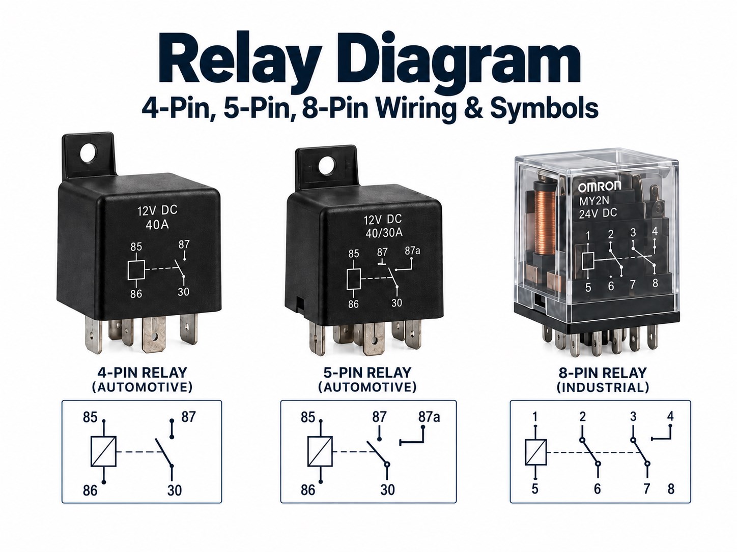
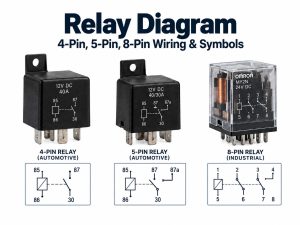
Relay diagram showing 4-pin 5-pin and 8-pin relay wiring and symbols

Key Takeaways

  • A relay diagram shows how the relay coil controls one or more electrical contacts and how those contacts connect or disconnect the load circuit.
  • The easiest way to read any relay is to separate it into a control side and a load side. The coil belongs to the control side; COM, NO, and NC belong to the switched side.
  • On common automotive relays, terminals 85 and 86 are typically the coil, 30 is common, 87 is normally open, and 87a is normally closed.
  • A common 4-pin automotive relay is usually SPST and normally open, while a common 5-pin version adds a normally closed contact and behaves as an SPDT relay.
  • An 8-pin relay is often DPDT, while many 14-pin relays provide four changeover contact sets. Physical pin numbering is not universal, so the datasheet must still be checked.
  • Relay schematic symbols, wiring diagrams, pin diagrams, and PCB footprints describe different things. A correct schematic can still produce a wrong PCB if the footprint orientation or pin mapping is mirrored.
  • Coil polarity may matter when a relay contains an internal diode, LED, or other polarity-sensitive suppression component.

What Is a Relay Diagram?

A relay diagram shows the relay coil, switching contacts, terminal functions, and the electrical relationship between the control circuit and the load circuit.

Several diagram types are commonly called a “relay diagram,” although they provide different information:

  • Schematic diagram: Shows electrical function.
  • Wiring diagram: Shows how wires connect between devices.
  • Pin diagram: Shows terminal or pin assignments.
  • Internal relay diagram: Shows the coil and contact arrangement inside the relay.
  • PCB footprint: Shows the actual pad or hole positions used for board layout.

A schematic may tell you that a relay is SPDT, but it does not necessarily tell you which physical pin is at the top-left corner of the package. That information comes from the relay pinout or package drawing.

This is why a relay diagram should always be matched to the exact relay model before wiring or creating a PCB footprint.

How Does a Relay Diagram Separate the Control Side from the Load Side?

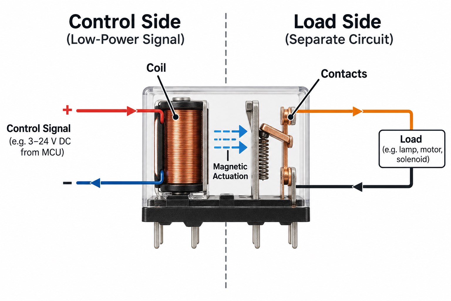
A relay diagram normally separates the device into a control side containing the coil and a load side containing the contacts.

The relationship can be simplified as:

Control voltage → Coil → Magnetic force → Moving contact → Load circuit changes state

The coil is electrically isolated from the switched contacts in a conventional electromechanical relay. Applying the rated coil voltage creates a magnetic field that moves an armature and changes the contact position.

For example, a 12V control signal may energize a relay coil while the contacts switch a higher-current lamp, motor, pump, heater, or another circuit.

Relay control side and load side showing coil magnetic actuation and isolated contacts

What Do Coil, COM, NO and NC Mean on a Relay Diagram?

Coil, COM, NO, and NC describe the main functional parts found in common electromechanical relay diagrams.

Marking Meaning Coil De-Energized
Coil Electromagnetic control input No magnetic actuation
COM Common moving contact Connected according to normal state
NO Normally Open Open
NC Normally Closed Connected to COM

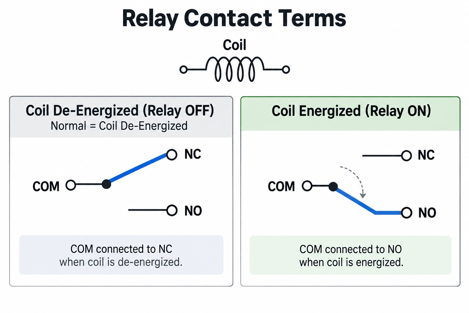
The word “normally” means the relay coil is not energized. It does not describe the state during normal machine operation.

In an SPDT relay, COM connects to NC when the coil is off. When the coil is energized, the contact moves away from NC and connects COM to NO.

Relay contact terms showing COM NO and NC when coil is de-energized and energized

Relay Diagram Symbols: How Do You Read the Coil and Contacts?

Relay symbols show the electrical relationship between the coil and the contacts rather than the physical appearance of the relay.

A schematic typically includes:

  • A coil symbol
  • One or more contact symbols
  • NO or NC contact positions
  • A dashed mechanical relationship between the coil and contacts
  • A device designator such as K1, K2, RY1, or REL1

A dashed line between the coil and contacts represents mechanical linkage, not an electrical wire. When multiple contact sets share the same relay designation, one coil operates all of those contacts together.

4-Pin vs 5-Pin Relay Diagram: What Do 30, 85, 86, 87 and 87a Mean?

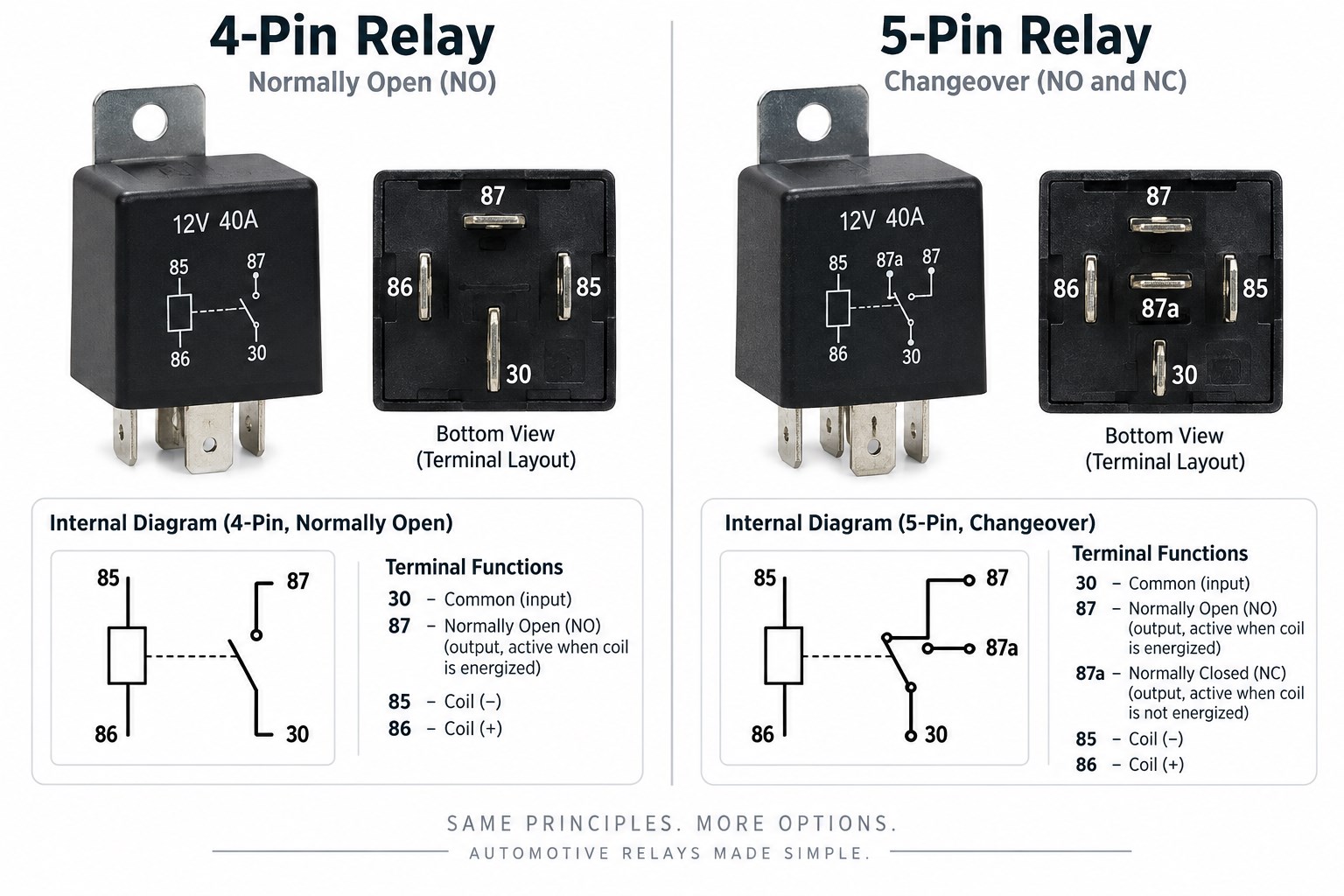
A common automotive 4-pin relay uses terminals 30, 85, 86, and 87, while the common 5-pin changeover version adds terminal 87a.

A 4 pin relay diagram shows the coil and normally-open switching path. A 5 pin relay diagram adds the 87a normally-closed path.

Terminal Common Automotive Function
85 Coil
86 Coil
30 Common power contact
87 Normally open contact
87a Normally closed contact

A typical 4-pin automotive relay is an SPST normally-open relay. With the coil off, 30 and 87 are open; when voltage is applied across 85 and 86, terminal 30 connects to 87.

A common 5-pin relay adds terminal 87a and usually operates as an SPDT changeover relay. With the coil off, 30 connects to 87a; when energized, 30 transfers to 87.

4-pin and 5-pin automotive relay diagram showing terminals 30 85 86 87 and 87a

How Do You Read an 8-Pin Relay Diagram?

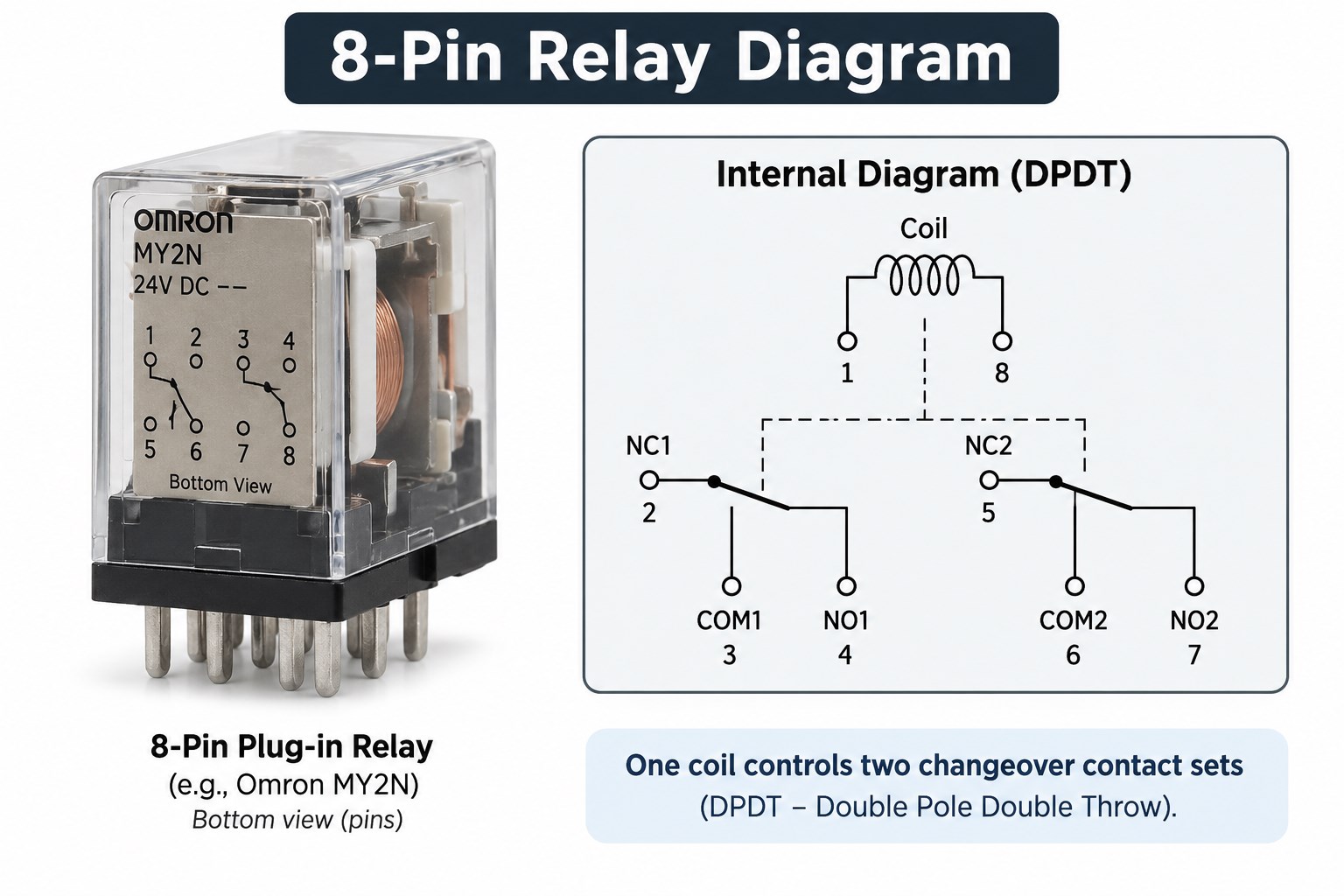
An 8-pin relay is commonly a DPDT relay containing one coil and two independent changeover contact sets. An 8 pin relay diagram therefore shows both contact sets operated by the same coil.

Its internal functions normally include:

  • 2 coil terminals
  • 2 COM terminals
  • 2 NO terminals
  • 2 NC terminals

That gives a total of eight pins. Conceptually, the relay contains two SPDT switches operated by the same coil.

There is no universal physical numbering arrangement for every 8-pin relay. The relay case diagram and datasheet should therefore be checked before connecting an 8-pin socket or creating a PCB footprint.

8-pin DPDT relay diagram with two changeover contact sets

What Does a 14-Pin Relay Diagram Usually Show?

A 14-pin relay often provides four changeover contact sets operated by one coil, commonly described as 4PDT or 4CO.

A typical functional breakdown is:

  • 2 coil terminals
  • 4 COM terminals
  • 4 NO terminals
  • 4 NC terminals

That totals 14 electrical connections. These relays are common in industrial control panels, PLC interface circuits, interlocking systems, alarm circuits, machine control, and signal distribution.

As with 8-pin relays, the 14-pin count does not guarantee one universal physical pin sequence. Socket numbering and terminal arrangement must be verified against the exact part number.

How Do You Read a 12V Relay Wiring Diagram?

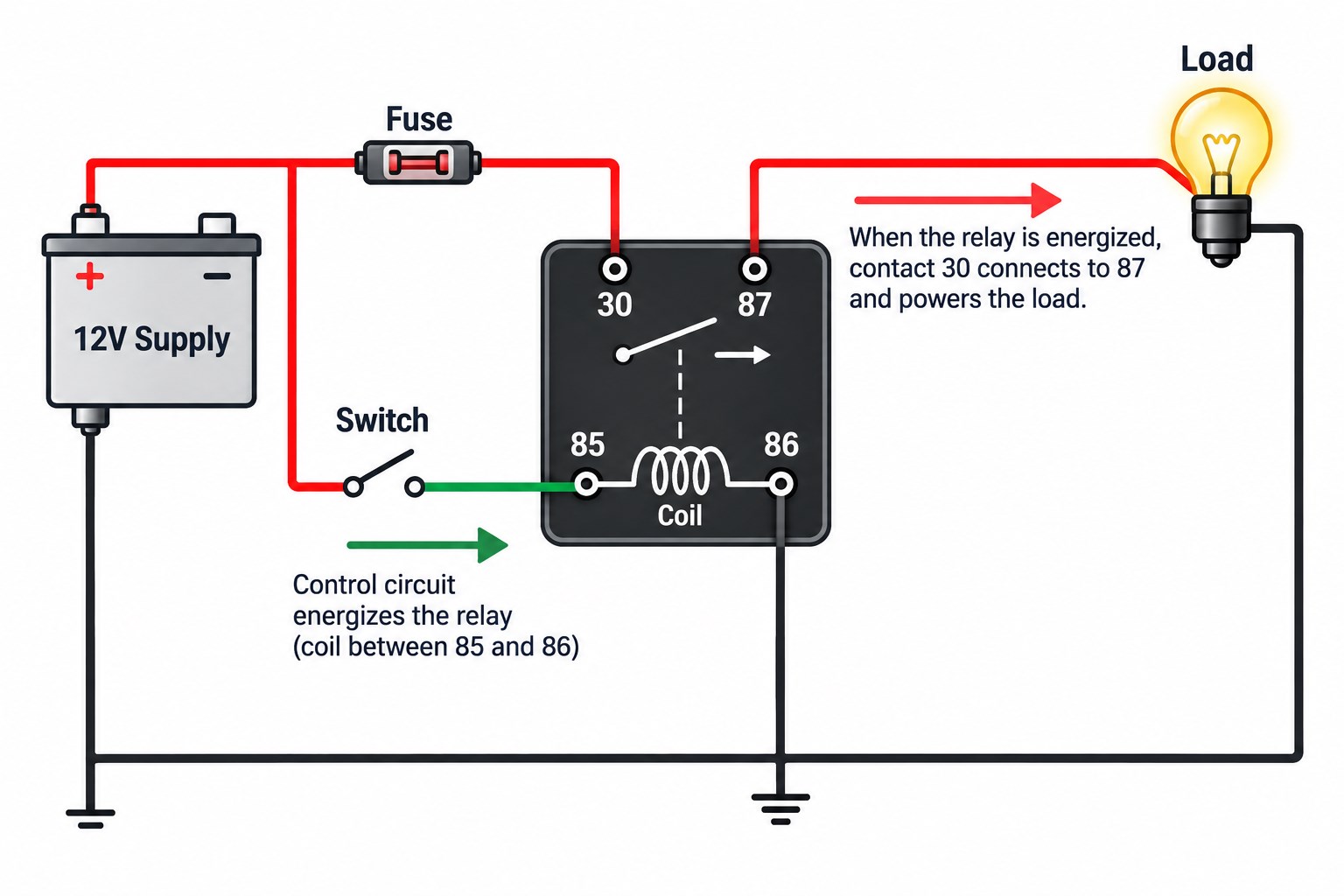
A 12V relay wiring diagram should be read by checking the coil circuit first and then tracing the switched load circuit.

  1. Confirm the coil voltage. Make sure the relay is actually rated for a 12V coil.
  2. Identify the coil pins. These may be 85/86 on automotive relays or A1/A2 on industrial designs.
  3. Identify COM, NO, and NC. Determine which contact state the application needs.
  4. Check coil polarity. A plain coil may not be polarity-sensitive, but an internal diode or LED can make polarity mandatory.
  5. Protect the control device. Use appropriate coil suppression when required.
  6. Fuse the load circuit. The relay does not replace proper overcurrent protection.
  7. Check contact current and voltage ratings. Motor and lamp loads may have high startup current.
  8. Confirm wire size and grounding. The wiring must suit the actual load current.
12V 4-pin relay wiring diagram showing supply fuse switch coil terminals 85 86 and contacts 30 87

Where Are 4-Pin and 5-Pin Relay Diagrams Commonly Used?

Four-pin and five-pin automotive relay diagrams appear in many systems where a low-current control signal operates a higher-current electrical load.

Application Typical Relay Role
Horn Switch controls higher-current horn circuit
Starter Ignition/control path operates starter solenoid circuit
Fuel pump ECU or control circuit switches pump supply
Auxiliary light Dashboard switch controls lighting load
Cooling fan Sensor or ECU controls fan motor
Compressor Control circuit switches compressor clutch
Heater Low-current controller switches heating load

A horn relay, starter relay, fuel-pump relay, or driving-light relay still follows the same basic coil-and-contact logic. The application name does not define the internal relay pinout, so the actual relay markings must still be checked.

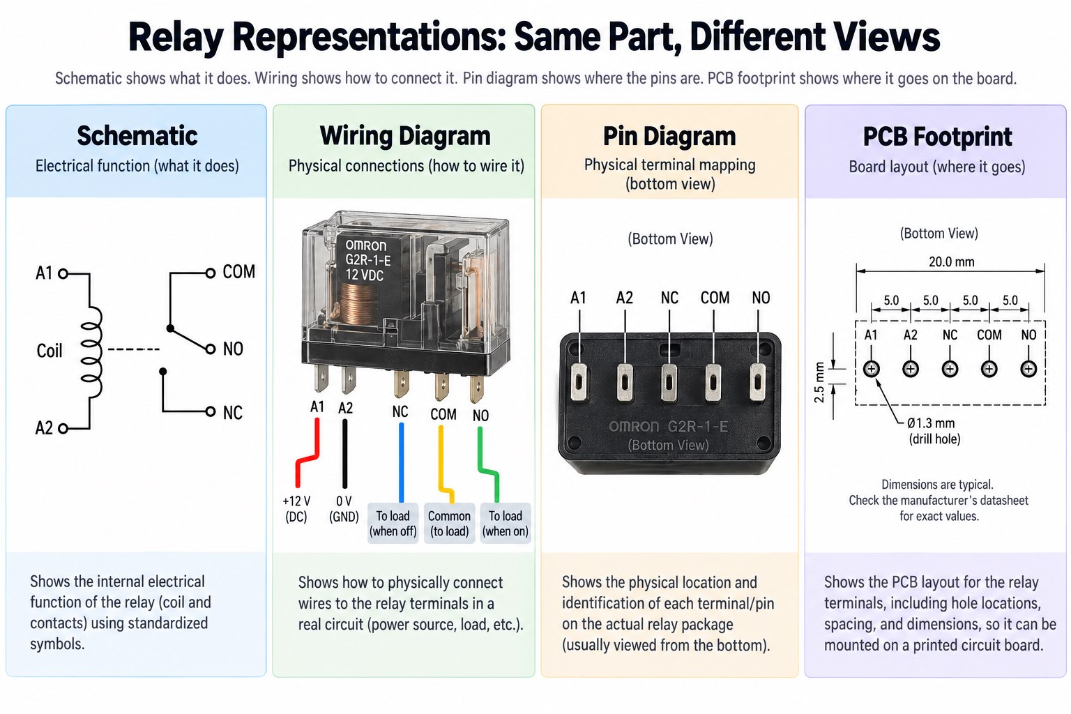
Relay Diagram vs Wiring Diagram vs Pin Diagram: What Is the Difference?

A relay schematic, wiring diagram, pin diagram, and PCB footprint answer different engineering questions.

Diagram Type Main Question It Answers
Relay schematic What does the relay do electrically?
Wiring diagram Where should each wire connect?
Pin diagram Which physical terminal performs each function?
Internal diagram How are the coil and contacts arranged?
PCB footprint Where are the actual pads or holes?

A schematic may show an SPDT relay as a coil plus COM, NO, and NC contacts. The wiring diagram then shows how those terminals connect to the power supply, switch, and load.

A relay pin diagram maps those functions to physical relay pins. Finally, the PCB footprint converts the mechanical package into copper pads or plated through holes.

Relay schematic wiring diagram pin diagram and PCB footprint comparison

What Should You Check Before Using a Relay Diagram for PCB Design?

Before placing a relay on a PCB, verify the physical pinout against the exact manufacturer datasheet rather than relying on a generic relay diagram.

Important checks include:

  • Datasheet drawing orientation
  • Top view versus bottom view
  • Coil pin locations
  • COM / NO / NC pin mapping
  • Coil voltage
  • Coil current
  • Internal suppression components
  • Contact current and voltage rating
  • Load type
  • Contact resistance
  • PCB hole size
  • Pad diameter
  • Relay body clearance

The coil also affects the surrounding circuit. A microcontroller normally cannot drive many relay coils directly, so the PCB may need a BJT or MOSFET driver, base or gate resistor, flyback diode, LED indicator, optocoupler, or separate relay supply rail.

For higher-voltage loads, creepage and clearance between the control side and switched contacts must also be reviewed. A correct schematic symbol can still produce a wrong PCB if the footprint is mirrored or the physical pinout is interpreted from the wrong viewing direction.

EBest Circuit can review relay footprints, driver circuits, through-hole assembly, isolation spacing, trace current capacity, and PCBA requirements during DFM before fabrication.

FAQ About Relay Diagrams

1. What does a relay diagram show?
A relay diagram shows the relationship between the coil and switching contacts, including functions such as COM, NO, and NC.

2. What do 85 and 86 mean on a relay?
They are commonly the coil terminals on standard automotive relays. The actual relay marking or datasheet should still be checked.

3. What is the difference between a 4-pin and 5-pin relay?
A common 4-pin automotive relay provides a normally-open switching path, while a common 5-pin changeover relay adds terminal 87a for the normally-closed path.

4. What is an 8-pin relay diagram?
An 8-pin relay is commonly a DPDT relay with two changeover contact sets and one coil. Physical pin numbering varies by model.

5. Does relay coil polarity matter?
Not always. Polarity becomes important when the relay contains an internal diode, LED, or another polarity-sensitive suppression circuit.

6. Can I use the same relay diagram for every relay with the same number of pins?
No. The same pin count can be used by relays with different contact forms, internal features, and physical pin assignments. Always verify the exact datasheet.

Designing a PCB Around a Relay?

A relay diagram explains the electrical switching function, but reliable PCB implementation also depends on the actual footprint, coil driver, suppression method, load current, isolation spacing, and assembly process.

EBest Circuit supports relay control PCB fabrication, through-hole and SMT assembly, DFM review, component sourcing, and functional testing. If you have a similar control-board project, send your Gerber files, BOM, schematic, and relay specifications to sales@bestpcbs.com for engineering review.

You may also like

MCB Circuit Breaker Symbol: 1P, 2P, 3P, 4P & Single-Line Diagrams

September 17th, 2026

An MCB symbol looks simple, but reading it correctly requires more than recognizing a breaker-shaped graphic. A drawing may use IEC conventions, ANSI/IEEE-style symbols, manufacturer-specific CAD libraries, or a simplified symbol created for a single-line diagram. The same protective function can therefore appear differently from one project to another.

The practical approach is to treat the symbol as one piece of information. Pole count, device tag, current rating, trip characteristic, breaking capacity, and the project legend complete the picture. This becomes especially important when distinguishing 1P, 2P, 3P, 4P, MCB, MCCB, and other protective devices.

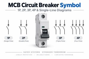
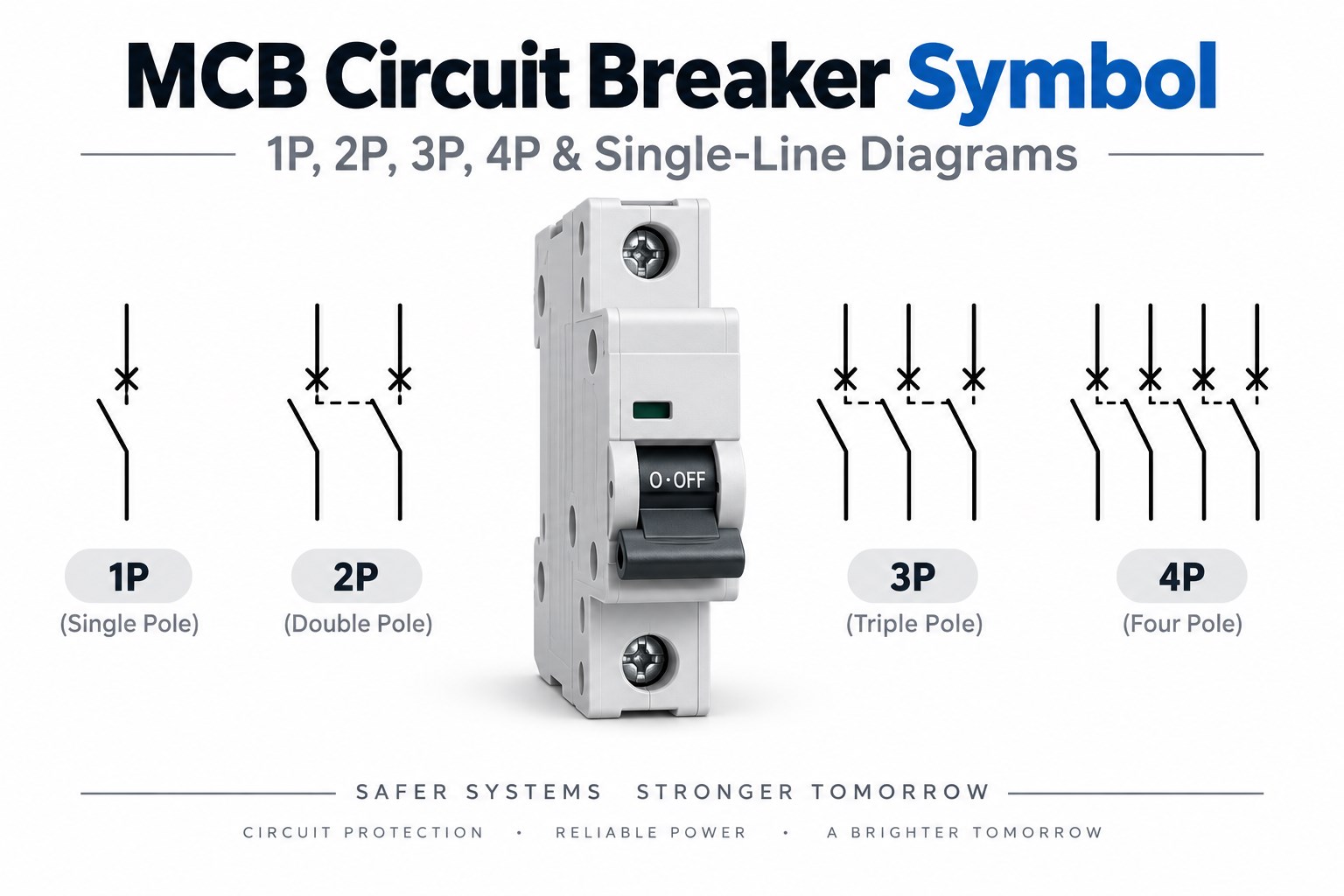
MCB circuit breaker symbol guide showing 1P 2P 3P 4P and single-line diagram

Key Takeaways

  • An MCB circuit breaker symbol represents a miniature circuit breaker used mainly for overload and short-circuit protection, but the exact graphic can vary by drawing standard and diagram type.
  • There is no single MCB symbol that appears identically on every schematic. IEC, ANSI/IEEE-style drawings, CAD libraries, and project legends may use different representations.
  • 1P, 2P, 3P, and 4P MCB symbols mainly indicate how many conductors are switched together. 1P+N and 3P+N configurations need additional attention because the neutral pole may be switched without having the same protective function as the phase poles.
  • A three-phase MCB may appear as three mechanically linked contacts on a detailed schematic, but a single-line diagram can represent the same three-pole breaker with one compact symbol.
  • The symbol alone usually does not tell you the current rating, trip curve, breaking capacity, AC/DC suitability, or exact product type.
  • MCB and MCCB symbols can look similar on simplified diagrams. Device tags, ratings, schedules, and specifications are often needed to tell them apart.
  • When reading an electrical drawing, always use the project legend, pole annotation, breaker tag, and ratings together rather than identifying the device from shape alone.

What Does MCB Mean and What Does an MCB Do?

MCB stands for Miniature Circuit Breaker. It is an automatically operated protective switching device commonly used to interrupt a circuit when an overload or short circuit exceeds the breaker’s operating limits.

Unlike a fuse, an MCB can normally be reset after the fault has been cleared. It also provides manual switching, although its primary role in the circuit is protection rather than routine control.

Typical MCB applications include:

  • Residential distribution boards
  • Commercial branch circuits
  • Lighting circuits
  • Small motors
  • Control panels
  • Industrial auxiliary circuits
  • Equipment power distribution

The exact protection characteristics depend on the device. Rated current, trip curve, breaking capacity, voltage rating, and pole configuration must therefore be checked separately from the schematic symbol.

What Does an MCB Circuit Breaker Symbol Mean?

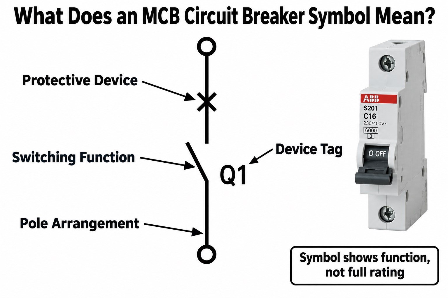
The MCB symbol meaning is that the circuit contains a protective switching device capable of automatically interrupting fault current.

Depending on the drawing style, the symbol may show a switching contact, a break in the conductor path, a protective-device qualifier, multiple mechanically linked poles, or a device tag such as CB1, QF1, or MCB1.

The graphic can help identify the function and sometimes the pole arrangement, but it usually does not provide the complete device specification. Rated current, trip curve, breaking capacity, voltage, AC/DC suitability, manufacturer, product series, and terminal arrangement normally come from annotations, schedules, or the component specification.

MCB symbol meaning showing protective device switching function pole arrangement and device tag

Is There One Standard MCB Symbol?

No. There is no single MCB graphic that appears identically in every electrical schematic, single-line diagram, and CAD library.

IEC 60617 provides standardized graphical symbols for electrical diagrams, including switching and protective functions. However, the symbol actually shown in a project can vary depending on how the standard is applied and how much detail the drawing needs.

Variation can come from IEC-based symbol libraries, ANSI/IEEE-style drawings, single-line diagrams, detailed control schematics, CAD software libraries, company drafting standards, and manufacturer documentation.

The correct method is therefore to check the drawing legend and project drafting standard first. A symbol should be interpreted in the context of the drawing in which it appears.

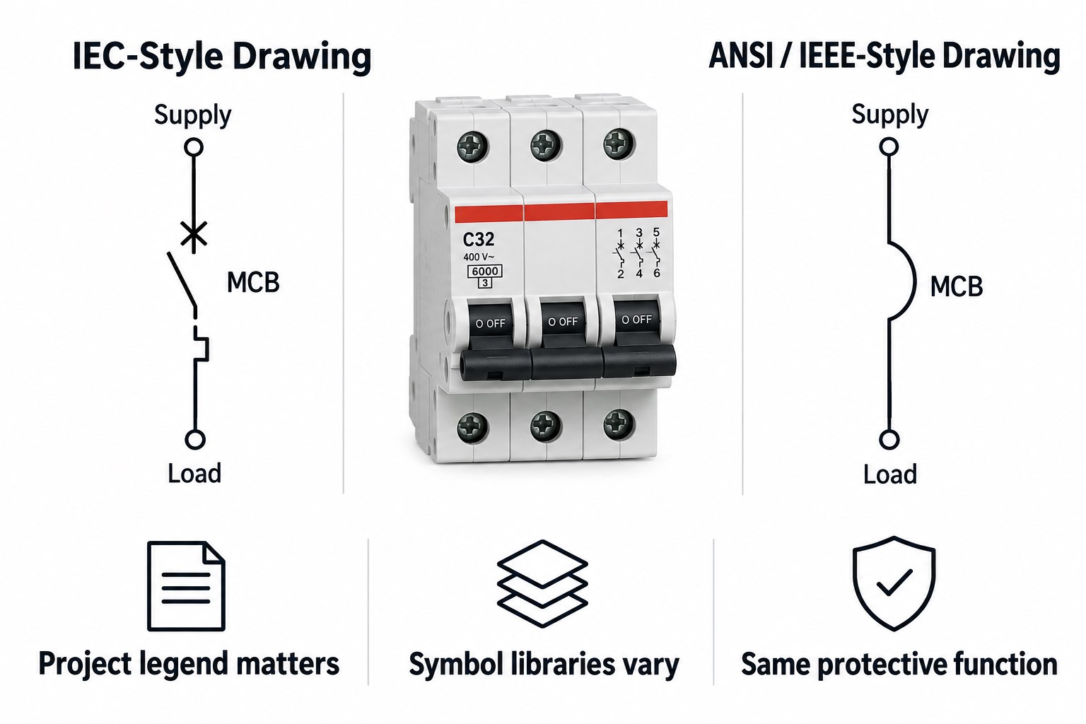
IEC vs ANSI/IEEE MCB Symbols: What Is the Difference?

IEC and ANSI/IEEE-style drawings can represent circuit-breaker functions differently, although both communicate the same basic idea: a protective device that can open the electrical path.

Drawing Convention Typical Characteristics
IEC IEC 60617 graphical conventions, IEC-style device designations
ANSI/IEEE North American symbol conventions and device numbering
Single-line diagram Simplified representation of multiphase circuits
Detailed schematic Individual contacts, coils, mechanical links, and terminals may be shown

Neither system changes what the MCB physically does. The main risk is assuming a symbol copied from one standard must look exactly the same in another drawing. In real engineering documentation, the project legend remains the safest reference.

IEC versus ANSI IEEE style MCB circuit breaker symbol comparison

1P vs 2P vs 3P vs 4P MCB Symbols: What Changes?

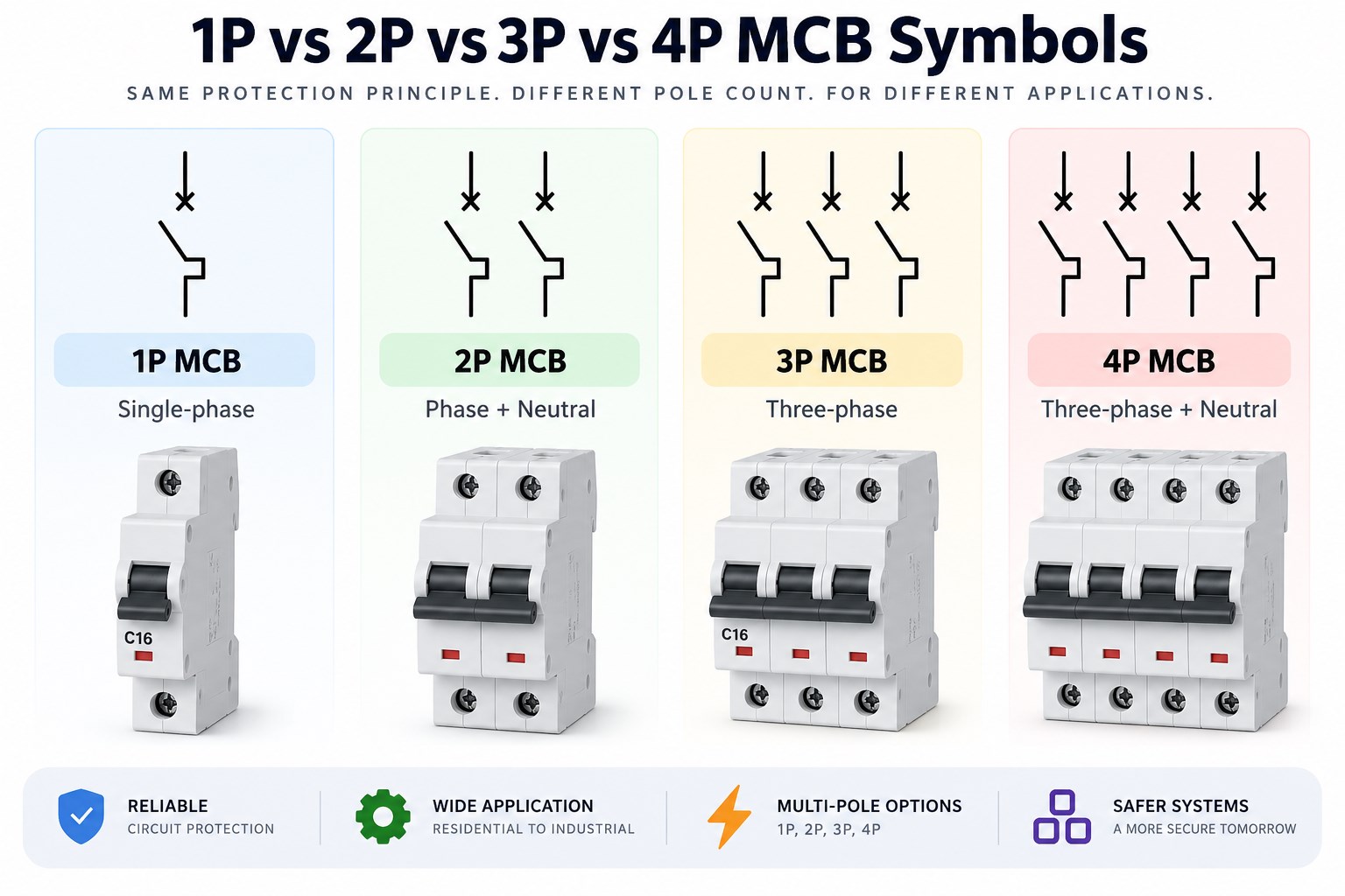
The main difference between 1P, 2P, 3P, and 4P MCB symbols is the number of conductors operated together by the breaker.

MCB Configuration Conductors Switched Typical Application
1P 1 Single-phase branch circuit
2P 2 Phase + neutral or two-line circuit
3P 3 Three-phase circuit
4P 4 Three-phase + neutral
1P+N 2 Single-phase with switched neutral
3P+N 4 Three-phase with switched neutral

A 1P MCB normally interrupts one live conductor. A 2 pole MCB symbol represents two mechanically linked poles operating together, while a 3P MCB mechanically links three poles for a three-phase system. A 4 pole MCB symbol adds a fourth switched path, commonly used when the neutral must also be disconnected.

However, 1P+N and 3P+N should not automatically be treated as identical to 2P and 4P protective devices. In some constructions, the neutral pole is switched but does not provide the same overcurrent protection as the phase pole.

1P 2P 3P and 4P MCB symbols with corresponding breaker configurations

What Does a 3-Phase Circuit Breaker Symbol Show?

A 3 phase circuit breaker symbol represents one breaker operating across all three phase conductors together.

In a detailed schematic, the drawing may show three separate contacts with a mechanical linkage between them. That linkage indicates that the poles operate together as one device.

In a single-line diagram, however, the entire three-phase circuit is represented by one line. The breaker may therefore appear as one compact symbol with annotations such as 3P, 3Ø, CB1, QF1, C32, or 10 kA.

A single line in an SLD does not mean the breaker has only one pole. Mechanical linkage shows simultaneous operation; it is not another current-carrying wire.

How Do You Read an MCB Symbol on a Single-Line Diagram?

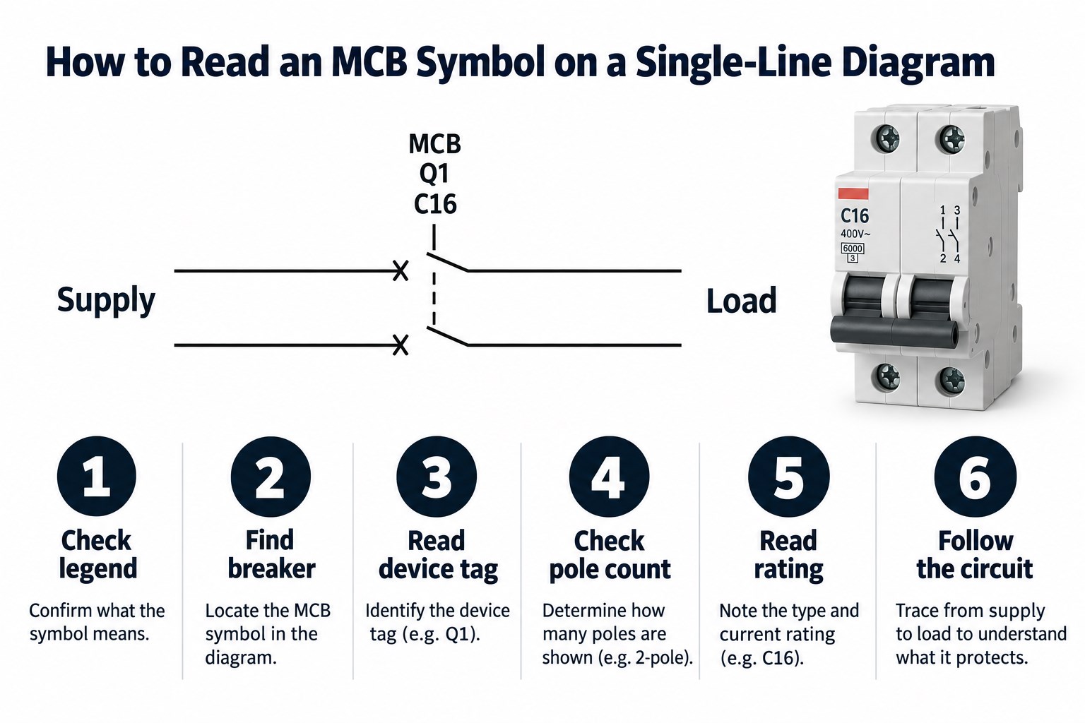
Reading an MCB on a single-line diagram is easier when you follow the information in a fixed order instead of relying on the symbol shape alone.

  1. Check the drawing legend. Confirm what the project uses for MCBs, MCCBs, isolators, fuses, and switches.
  2. Locate the breaker symbol. Follow the incoming supply or feeder until you reach the protective switching device.
  3. Read the device tag. Common tags include MCB1, CB1, QF1, or Q1.
  4. Check the pole configuration. Look for 1P, 2P, 3P, 4P, 1P+N, or 3P+N.
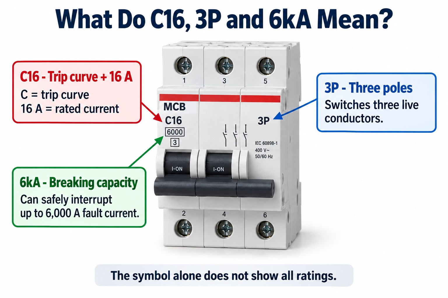
  5. Read the current and trip information. A label such as C16 commonly indicates a C-characteristic 16 A MCB.
  6. Check breaking capacity and voltage. Values such as 6 kA or 10 kA describe short-circuit interruption capability under the applicable rating conditions.
  7. Follow the circuit upstream and downstream. Confirm where the breaker receives power and which load, bus, or subcircuit it protects.
How to read an MCB symbol on a single-line diagram step by step

What Do MCB Labels Such as C16, 3P and 6kA Mean?

MCB labels provide electrical information that the schematic symbol itself usually cannot communicate.

Marking Typical Meaning
C C-type tripping characteristic
16 16 A rated current
3P Three-pole device
6 kA Rated short-circuit breaking capacity under the applicable rating standard

A B, C, or D designation normally relates to the magnetic trip characteristic rather than the number of poles. Similarly, 6 kA does not mean the breaker is intended to carry 6,000 A continuously. It describes the short-circuit current the device is rated to interrupt under specified test conditions.

MCB marking explanation for C16 3P and 6kA

MCB vs MCCB Symbols: Can You Tell Them Apart by Shape?

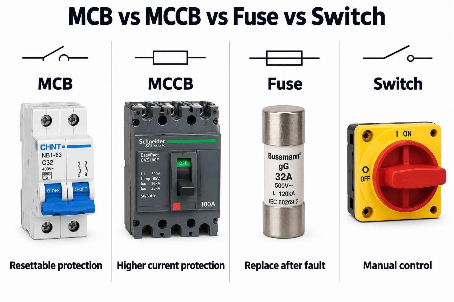
Not always. An MCB and an MCCB can share a generic circuit-breaker symbol in simplified drawings because both perform the same basic protective switching function.

The difference may only become clear from surrounding information. Check the device tag, MCB/MCCB annotation, rated current, frame size, breaking capacity, adjustable trip settings, electronic or thermal-magnetic trip unit, equipment schedule, and manufacturer part number.

An MCCB is generally used for higher current levels and more demanding distribution applications, while an MCB is typically used for lower-current final or branch circuits. However, symbol shape alone should not be used to determine the product category.

MCB vs Fuse vs Switch Symbol: How Do You Avoid Misreading Them?

MCBs, fuses, and switches can all interrupt a circuit, but their functions are different.

Device Automatic Fault Protection Resettable Main Purpose
MCB Yes Yes Overload / short-circuit protection
MCCB Yes Yes Higher-current protective switching
Fuse Yes No Overcurrent protection
Switch Not necessarily Yes Manual switching

An MCB combines switching with automatic overcurrent protection. A fuse also provides automatic protection, but once its element melts, the fuse must be replaced. A normal switch can open the circuit manually but should not be assumed to provide overload or short-circuit protection unless it is part of a protective device.

MCB MCCB fuse and switch symbol and device comparison

What Information Should Be Checked Beyond the MCB Symbol?

The MCB symbol identifies the device function, but selecting or verifying the physical breaker requires more information.

Engineers should check:

  • Rated current
  • Pole count
  • Rated voltage
  • AC or DC operation
  • Trip characteristic
  • Breaking capacity
  • Frequency
  • Installation category
  • Terminal arrangement
  • Applicable standard
  • Manufacturer and part number

The same distinction matters when an MCB connects to a PCB-based control system. The schematic symbol is not the physical footprint.

A control PCB may interface with auxiliary contacts, shunt-trip coils, undervoltage release, remote actuators, current sensors, status inputs, or DIN-rail terminal blocks. Connector pitch, terminal current, creepage, clearance, relay ratings, and isolation barriers must therefore be designed from the actual hardware specification rather than from the MCB symbol shown in the system schematic.

FAQ About MCB Circuit Breaker Symbols

1. What is the full form of MCB?
MCB stands for Miniature Circuit Breaker. It is mainly used for automatic overload and short-circuit protection in lower-current electrical circuits.

2. What is the symbol of an MCB?
The exact symbol depends on the drawing standard and diagram type. IEC-based schematics, ANSI/IEEE-style drawings, and single-line diagrams may represent the breaker differently, so the project legend should be checked.

3. What is the difference between a 1P and 2P MCB symbol?
A 1P MCB operates one conductor, while a 2P MCB operates two mechanically linked conductors together.

4. What is the symbol for a 3-phase MCB?
A detailed schematic may show three mechanically linked breaker contacts. In a single-line diagram, one breaker symbol marked 3P may represent the complete three-phase device.

5. Is the MCB symbol different from the MCCB symbol?
Not necessarily. Simplified electrical drawings can use the same basic circuit-breaker symbol for both, with annotations or schedules identifying whether the device is an MCB or MCCB.

6. Can an MCB symbol tell me whether the breaker is AC or DC?
Usually not. AC/DC suitability should be confirmed from the rating annotation, project specification, and manufacturer datasheet rather than inferred from the symbol shape.

Reading an MCB Symbol on a PCB-Based Control System?

An MCB symbol can identify the protective device on the electrical schematic, but PCB design requires the actual breaker interface to be reviewed separately. Auxiliary contacts, control voltages, terminal spacing, isolation, relay outputs, and sensing circuits all affect the final board.

EBest Circuit supports industrial control PCB fabrication, DFM review, component sourcing, PCBA, and functional testing. If your control-board project interfaces with breakers, relays, contactors, or other power devices, send your Gerber files, BOM, schematic, and electrical requirements to sales@bestpcbs.com for engineering review.

You may also like

Locker Control Board for Multi-Door Smart Locker Systems

September 15th, 2026

A locker control board is the electronic link between a smart locker’s host system and its individual doors. It receives an unlock command, drives the correct electronic lock, reads the resulting door or compartment status, and reports the result to the host. In a multi-door cabinet, these actions must remain reliable across every channel—not only on the first working prototype.

That makes the board more than a simple relay module. Its architecture must match the number and type of locks, the communication network, the available power supply, the sensing method, and the required test coverage. EBest Circuit supports prototype and production PCBA for customer-released locker controller designs. To discuss a project, send the PCB files, BOM and functional requirements to sales@bestpcbs.com.
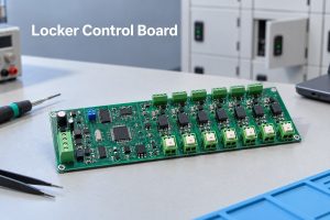
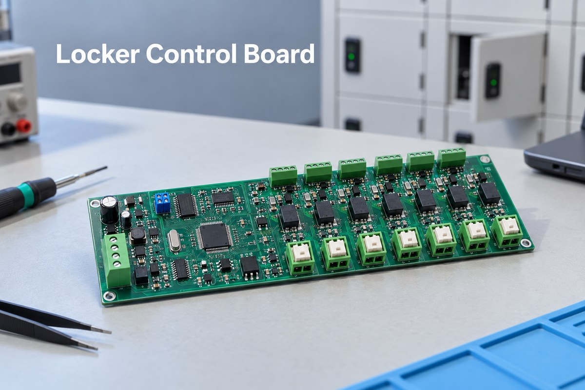
locker control board
Multi-channel locker control board for electronic locks, communication and status feedback.

What Is a Locker Control Board?

A locker control board controls the electronic hardware inside parcel lockers, vending lockers, school lockers, pharmaceutical cabinets and other multi-compartment systems. It may operate as the main controller or as a lower-level unit connected to a separate computer or gateway.

Its role can be separated clearly:

  • On the board: select a compartment, drive its lock, read door or occupancy signals, and control local indicators.
  • Usually elsewhere: user interface, payment, cloud connection, access rules and management software.

This boundary prevents unnecessary functions from being added to the PCB and clarifies what the locker control board must exchange with the host system.

How Is a Smart Locker Control Board System Structured?

Many multi-door locker systems use a modular structure rather than putting every function on one large PCB.

  • Host or main controller: Runs the user interface, access rules, network connection and application software.
  • Communication or bus unit: Converts commands from Ethernet, USB or another host interface into a field bus such as RS485.
  • Lock control unit: Provides multiple lock outputs and reads the corresponding feedback or sensor inputs.
  • Locks and sensors: Perform the physical action and return door, latch or occupancy information.

Placing lock units near the compartments shortens high-current wiring. Additional addressed units can add more doors without redesigning the host controller.

Typical choice: combine the host interface and lock drivers for a compact locker; use one gateway plus several addressed lock boards for a large cabinet.

locker control board
Distributed control boards connect a locker gateway to individual electronic locks and sensors.

How Many Locks Can One Locker Control Board Manage?

Commercial locker boards commonly provide 8, 16 or 24 lock channels. Start with the compartment count: each door needs a lock output and the corresponding feedback and indicator connections. If the product family uses several cabinet sizes, a few spare channels can keep one controller platform usable across more than one model.

Then apply the electrical limit. The combined pulse current of every lock that may open together must remain within the PCB power path, connectors and external supply. For example, a 48-door cabinet can use two uniquely addressed 24-channel boards instead of concentrating 48 high-current outputs on one PCB. The “24-channel” label is meaningful only when the feedback I/O, power budget and bus architecture also support 24 doors.

How Do RS485 and TCP/IP Connect a Locker Control Board to the Host System?

TCP/IP and RS485 normally serve different links in the same system:

Interface Typical link Main reason to use it
TCP/IP Network or server to locker gateway Connects management software and remote services
RS485 Gateway to distributed lock boards Supports addressed boards over longer cabinet wiring

RS485 still requires the correct termination and biasing arrangement, transient protection where needed, controlled connector pinouts and a clear grounding strategy. The firmware protocol must define addresses, commands, acknowledgements and fault behavior. Adding a transceiver alone does not make the bus reliable.

How Does a Locker Control Board Monitor Doors and Compartments?

A locker control board monitors each compartment through separate inputs tied to the same channel number as its lock output. After the host commands channel 12, latch feedback can show that the lock released, a door switch can show whether door 12 actually opened, and an occupancy sensor can show whether the item was removed. The controller reports these events separately instead of returning one vague “success” status.

This separation lets the host distinguish an electrical release from a completed pickup. It can also identify cases such as “lock released but door stayed closed” or “door closed but latch not engaged.” The status LED is an output that communicates the resulting state to the user; it is not a substitute for the feedback inputs. Long sensor wiring may require filtering and protection so that noise does not create a false door event.

How Does a Locker Control Board Drive Solenoid and Motor Locks?

The two lock types need different drive behavior:

Lock type Typical drive action Main PCB consequence
Solenoid lock Apply a defined release pulse Size the switching path for pulse current and suppress the inductive transient
Motor lock Run for a controlled interval, sometimes with polarity reversal Provide direction control and stop the drive at the correct time

MOSFETs are commonly used for compact, efficient DC switching. Relays are more appropriate when the design needs isolated or flexible contacts, but they consume more board space and have a finite mechanical life. Whichever device is selected, the PCB power path, connectors and external supply must carry the worst-case current when multiple doors are released—not merely the current of one lock.

Does a Locker Control Board Need a 2-Layer or 4-Layer FR-4 PCB?

The common choice is 2-layer or 4-layer FR-4:

PCB structure Better suited to
2-layer FR-4 A roomy expansion board with modest channel count, low-speed communication and simple sensor inputs
4-layer FR-4 A compact controller combining an MCU, dense connectors, communication, many outputs and multiple inputs

Four layers provide clearer ground and power planes and reduce routing congestion, but more layers do not automatically make a better controller. A roomy 8-channel board may work well in two layers, while a compact 24-channel controller may justify four. Freeze the stackup before final placement because a late layer change affects grounding, vias, routing and PCBA cost.

When Does a Locker Control Board Need HDI, Heavy Copper or BGA Assembly?

Most locker control boards need none of these three technologies. A conventional 2-layer or 4-layer FR-4 PCB with plated through holes and standard SMT packages is normally sufficient for a multi-channel lock controller.

HDI becomes justified only when the permitted board area and fine-pitch routing cannot be resolved with conventional through vias. Heavy copper becomes justified only when the simultaneous lock current cannot be carried practically with wider standard-copper pours and shorter power paths. In many locker designs, staged lock operation avoids that current concentration.

BGA assembly depends mainly on the selected processor rather than the locker application itself. A conventional MCU in QFP or QFN normally avoids BGA. A compact Linux controller that integrates processing, memory and networking is more likely to require BGA placement, X-ray inspection and escape routing. The design should add HDI, heavy copper or BGA only after a real space, routing or current limit rules out the conventional construction.

What Makes Multi-Channel Locker Control Board Assembly and Testing Difficult?

The challenge is repetition. A solder defect, incorrect connector, reversed driver device or wrong component value can affect only one of many otherwise identical channels. A board may power up and communicate normally while one locker door still fails in service.

Mixed assembly can add another difficulty. Locker controllers often combine fine-pitch SMT control electronics with relays, terminal blocks, pin headers or other through-hole parts. The assembly process must keep polarity and orientation correct while protecting tall connectors and mechanically loaded joints.

Visual inspection and continuity testing cannot demonstrate full operation. A production fixture should repeat one closed-loop sequence for every populated channel:

  1. Send a command to channel 1.
  2. Apply a representative lock load and confirm the output.
  3. Switch the paired door or occupancy input.
  4. Verify that the host reports channel 1.
  5. Repeat for every remaining channel.

Firmware revision and total supply current can be checked once for the complete board.

The fixture does not need dozens of physical locker doors. Electrical loads and switch simulation can test every channel efficiently, while a first article fitted with the actual lock confirms that the simulated current and feedback conditions represent the application.

locker control board
A functional fixture verifies each locker output and its paired feedback channel.

How Does EBest Circuit Build and Test Multi-Channel Locker Control Board Assemblies?

The greatest manufacturing risk on a multi-channel locker board is that one repeated error can appear 8, 16 or 24 times. EBest Circuit reviews the repeated driver circuits, connector numbering, polarity and test-point access before assembly, helping prevent a mirrored connector or incorrect protection device from being copied across the complete board.

The prototype is built as a usable assembly rather than a bare PCB alone. PCB fabrication, sourcing through a network of more than 1,000 supply-chain partners, SMT and through-hole assembly can cover the MCU, communication devices, MOSFETs or relays, terminal blocks and cabinet connectors in one project. This allows the customer to connect the first articles to the intended locks and wiring before releasing the next quantity.

For production, the functional fixture follows the actual channel map. It verifies that each command activates the matching output and that the paired door or occupancy input returns to the correct address. Firmware revision, material batch and production progress can be linked through EBest Circuit’s digital workshop, where material and product batch information can be traced within five seconds.

With more than 20 years of PCB and PCBA experience, EBest Circuit supports prototypes, small batches and repeat orders under ISO 9001, ISO 13485, IATF 16949 and AS9100D quality systems. The practical benefit is a locker control board that arrives assembled, channel-tested and traceable, ready for the customer’s cabinet-level validation.

FAQs About Locker Control Board

Can one locker control board operate different types of electronic locks?

Yes, if the output circuit and firmware match the voltage, current, pulse duration and feedback method of each lock. A board designed for a low-current solenoid should not be assumed to support a motor lock without checking the driver and power architecture.

Is RS485 necessary for every smart locker?

No. A compact locker may connect its controller directly to the host. RS485 becomes especially useful when multiple lock boards are distributed through a larger cabinet or when the communication cable must cover a longer distance in a noisy environment.

Does a 24-channel board open all 24 locks at the same time?

Not necessarily. Channel count describes how many locks the board can address, not how many it can energize simultaneously. The permitted simultaneous operation depends on the output devices, copper distribution, connectors and external power supply.

Does a locker control board require a 4-layer PCB?

Not always. A simple expansion board may use two layers. Four layers are more appropriate when processing, communication, sensor inputs and many lock outputs create dense routing or demanding power and grounding needs.

What information is most useful for a locker control board PCBA quotation?

The PCB data, BOM, placement file and required quantity are enough to begin a manufacturing review. It also helps to identify the lock voltage and current, number of channels, programmed components, through-hole parts and expected functional test. EBest Circuit can review the available package first and identify any missing production details without asking the customer to prepare an unnecessary document set.

A reliable locker control board must do more than switch an electronic lock. It must control the correct channel, communicate consistently, read meaningful feedback and pass the same functional checks across every assembled board. For a locker controller PCB or PCBA review, contact EBest Circuit at sales@bestpcbs.com.
You may also like

Industrial Control PCB Manufacturer Australia: 10 Companies to Compare

September 8th, 2026

Finding the right industrial control PCB manufacturer Australia buyers can rely on is not simply a matter of choosing the nearest factory or the lowest unit price. A control board may operate pumps, motors, relays, sensors, safety circuits, or communication modules for years in an electrical cabinet. One weak solder joint, unsuitable laminate choice, undocumented component substitution, or incomplete functional test can stop the equipment that depends on it.

Australian OEMs therefore need to compare manufacturers by project fit: bare-board capability, component sourcing, assembly, inspection, testing, traceability, engineering response, and repeat-order control. EBest Circuit (Best Technology) supports this complete path through its own PCB and PCBA factories, a supply network of more than 1,000 partners, 20 years of PCBA experience, and quality systems including ISO 9001, ISO 13485, IATF 16949, and AS9100D. To discuss an industrial control PCB or PCBA requirement, contact sales@bestpcbs.com.
industrial control PCB manufacturer Australia
Industrial control PCBA inspection for an Australian OEM manufacturing project.

Industrial Control PCB Manufacturer Australia: 10 Companies to Compare in 2026

The following manufacturers represent different sourcing models available to Australian industrial-control buyers, including local PCB fabrication, contract electronics manufacturing, and Australian-managed supply routes.

  1. Alfatron – A Victoria-based manufacturer offering onshore PCB fabrication and assembly. Its published services include prototype assembly, AOI, ICT, X-ray inspection, conformal coating, and electromechanical assembly. It is a relevant candidate when sovereign Australian production is a firm requirement.
  2. Circuitwise Electronics Manufacturing – A Sydney-based contract electronics manufacturer serving high-reliability industrial and regulated applications. Its published scope includes SMT and through-hole assembly, FAI, 3D AOI, X-ray, box build, functional testing, and component-level traceability.
  3. Precision Electronic Technologies – An Australian engineering and manufacturing provider supporting PCB development, sourcing, assembly, and production. Its manufacturing network can suit buyers comparing local engineering access with a broader supply footprint.
  4. Elemental Electronics – A Victorian electronics developer and manufacturer focused on prototype and low-to-medium-volume production. It provides PCB assembly, product integration, test-fixture development, functional testing, and enclosure work.
  5. Hetech – A Brisbane electronics manufacturing provider offering prototyping, PCB assembly, inspection, testing, coating, and product integration. Its published industry coverage includes industrial automation and other high-reliability applications.
  6. Advanced Technology and Manufacturing (AT&M) – A Perth-based assembly provider supporting low- and higher-volume PCBA. Its published production capabilities include SMT, through-hole assembly, reflow, wave soldering, and workmanship aligned with IPC/J-STD requirements.
  7. OurPCB Australia – A PCB and PCBA supplier serving Australian customers through an overseas manufacturing model. It may fit buyers who want local communication while sourcing boards or assemblies from Asia.
  8. Rush PCB Australia – A supplier covering PCB prototypes, fabrication, and assembly for the Australian market. Buyers should confirm the production location, applicable capabilities, quality records, and test scope for their exact control-board build.
  9. QualiEco Circuits – An Australian supplier of PCB fabrication and contract assembly services. It can be considered for prototype, urgent, and repeat-order needs where an Asia-linked supply route is acceptable.
  10. Crystalaid – An Australian-owned and operated electronics manufacturer based in Queensland. Its published capabilities include SMT and through-hole PCB assembly, cable and harness assembly, testing, and box build for industrial and other high-reliability applications.

Shortlisting tip: Choose three or four candidates whose production model matches the project. Send each supplier the same controlled RFQ package and compare the resulting assumptions, exclusions, technical questions, test plan, evidence package, and delivery commitment – not only the quoted price.

Australia-Based vs China Industrial Control PCB Manufacturers

The better manufacturing location depends on what the project must protect. A local Australian supplier may be attractive when face-to-face engineering access, sovereign production, small local runs, or regulated procurement rules are decisive. A qualified China-based supplier can be competitive when the buyer needs a broader PCB process range, coordinated component sourcing, scalable assembly capacity, or cost control across repeat orders.

Decision Australia-based supplier China-based supplier
CommunicationLocal time zone and easier site accessConfirm response owner and engineering handoff
ProductionUseful when onshore manufacture is mandatoryBroader capacity and supply-chain options may be available
CostCan suit low-volume or locally controlled workOften competitive for integrated and repeat production
LogisticsShort domestic transport routeRequires freight, customs, and buffer planning

The country alone does not determine risk. Before nomination, compare revision control, approved-vendor handling, first-article approval, nonconformance response, test ownership, traceability, and the supplier’s ability to reproduce the same build months later.

Australian buyers can also use a hybrid sourcing strategy. Early engineering builds or sensitive programs may stay local, while a qualified China partner supports cost-controlled repeat production. The key is to release the same approved files, BOM, test limits, and change-control rules to every manufacturing route.

Industrial Control PCB Capabilities for Australian Automation Projects

EBest Circuit manufactures FR-4, heavy-copper, rigid-flex, metal-core, and ceramic boards for industrial controllers, power interfaces, motor-control units, and monitoring equipment.

Industrial-control requirement EBest Circuit capability
FR-4 layers and materials1–10 layers standard
Up to 32 layers after review
Low-, mid-, and high-Tg FR-4
Copper and geometryCopper up to 5 oz
4/4 mil line and space
0.20 mm finished holes
Special processesHeavy copper up to 20 oz
3/3 mil line and space
0.15 mm finished holes after review
Thickness and finishCommon thickness: 0.4–3.5 mm
HASL, OSP, ENIG, immersion silver/tin, ENEPIG, and hard gold
Other board typesRigid-flex: up to 20 layers
MCPCB: up to 10 layers
Thin-film, DBC, DPC, and AMB ceramic boards
industrial control PCB manufacturer Australia
Dimensional inspection of multilayer industrial control PCBs before assembly.

Special-process limits require project review. Send the Gerbers, drill files, fabrication drawing, stack-up, impedance requirements, IPC class, and critical tolerances. EBest Circuit can then confirm the production route and return DFM questions before release.

Industrial Control PCB Assembly for Australian Orders

EBest Circuit provides SMT, through-hole, and mixed-technology assembly for Australian industrial-control orders. This is useful for boards that combine fine-pitch ICs with relays, terminal blocks, transformers, large connectors, heat sinks, or other through-hole components.

PCBA item EBest Circuit capability
Placement capacityCompany capability data lists up to 13,200,000 component placements per day
Board sizeFrom 0.2 × 0.2 inches to 20 × 20 inches; boards up to 22 × 47.5 inches require project review
Small componentsDown to 01005 packages
Fine-pitch packagesBGA pitch down to 0.25 mm
Assembly processesSMT, THT, and mixed assembly
Component packagingReels, cut tape, tubes, trays, and loose parts
Assembly production timeCapability data lists 1–5 days, subject to BOM readiness, process complexity, inspection, and testing
industrial control PCB manufacturer Australia
Mixed-technology industrial control PCB assemblies moving through production.

EBest Circuit can manage turnkey, consigned, or partial-turnkey builds. The service can combine BOM review, approved component procurement, stencil preparation, solder-paste printing, placement, reflow, through-hole insertion, wave or manual soldering, programming, cleaning, coating, testing, and final packaging according to the released order scope.

Before purchasing components, the team reviews manufacturer names, part numbers, packages, quantities, lifecycle risks, and approved-substitution rules. When a part is obsolete or has an unsuitable lead time, EBest Circuit can prepare a BOM optimisation or alternative-parts list for customer approval. No substitute is released merely because stock is available.

To receive a complete PCBA quotation, provide the BOM, centroid data, assembly drawings, Gerbers, approved-vendor requirements, soldering standard, programming files, test procedure, first-article quantity, production quantity, and repeat-order forecast.

Testing Evidence for Industrial Control PCB Orders to Australia

EBest Circuit can provide a project-specific inspection and test evidence package for Australian industrial-control orders. The exact records are agreed before production so that the delivered documentation matches the customer’s acceptance plan.

Available production and quality evidence includes:

  1. incoming-material and component verification records;
  2. solder-paste inspection records when SPI is included in the process plan;
  3. AOI results covering component position, polarity, solder condition, and missing parts;
  4. X-ray images or records for BGA, QFN, and other bottom-terminated packages when required;
  5. bare-PCB open-and-short electrical-test results;
  6. ICT or flying-probe results where the board design and agreed test route permit them;
  7. programming confirmation and functional-test results measured against customer-approved limits;
  8. first-article inspection and approved-deviation records; and
  9. final inspection, serial-number, batch, material, and process-traceability records.
industrial control PCB manufacturer Australia
Functional and electrical verification of an industrial control PCBA.

EBest Circuit’s digital workshop records material and product batches, production stages, and manufacturing progress. This helps the team retrieve the corresponding production information quickly when a customer reviews a batch, repeat order, or quality issue.

For functional testing, the customer should provide the procedure, firmware version, expected inputs and outputs, pass/fail limits, connector pinout, fixture interface, golden sample, and any required load or communication simulator. EBest Circuit can then implement the approved test at PCBA level and return the agreed results with the shipment.

Quality Certifications for Industrial Control PCB Manufacturing in Australia

A certificate is useful only when its scope and controls match the project. Buyers should request the current certificate, issuing body, covered site, expiry date, and manufacturing scope rather than relying on a logo displayed on a website.

Match the evidence to the application:

  • ISO 9001 supports a general quality-management framework.
  • ISO 13485 may be relevant when the control assembly forms part of a medical-device supply chain.
  • IATF 16949 is relevant to automotive production controls when the project and manufacturing site fall within scope.
  • AS9100D supports aerospace and defence quality-system requirements when applicable.
  • IPC-A-600, IPC-A-610, IPC/WHMA-A-620, and J-STD-001 can define board, assembly, cable, and workmanship expectations when specified in the purchase package.

Beyond certificates, audit how the manufacturer controls incoming material, shelf life, calibration, ESD, nonconforming product, rework, corrective action, approved suppliers, engineering changes, and production records. The purchase order should state the required IPC class and any customer-specific acceptance criteria.

Lead Times for Industrial Control PCB Prototypes and Repeat Orders to Australia

EBest Circuit offers normal and expedited production for industrial-control prototypes. The published FR-4 times below apply to standard-specification prototype orders below one square metre. The PCBA figures cover assembly production and still depend on component readiness, fixture requirements, programming, coating, and the approved inspection plan.

Product Normal service Fastest service
1-layer FR-4 prototype7 days24 hours
2-layer FR-4 prototype8 days24 hours
4-layer FR-4 prototype10 days48 hours
6-layer FR-4 prototype10 days72 hours
8-layer FR-4 prototype12 days72 hours
PCBA1 week2 days

The standard FR-4 reference covers normal FR-4 material from 0.4–1.6 mm, 0.5 or 1 oz copper, lead-free HASL, green solder mask, white silkscreen, line width and spacing above 8 mil, minimum hole above 0.3 mm, and minimum annular ring above 10 mil. A control board with heavy copper, fine lines, controlled impedance, special laminate, blind vias, coating, or unusual testing needs a project-specific schedule.

For an Australian shipment, EBest Circuit confirms the manufacturing schedule after reviewing PCB complexity, BOM availability, first-article approval, testing, documentation, and freight requirements. Repeat orders can move faster when the approved Gerbers, BOM revision, placement program, stencil, fixture, test limits, golden sample, and deviations remain under the same controlled revision.

Why Australian OEMs Choose EBest Circuit for Industrial Control PCB Projects

EBest Circuit supports Australian buyers who want one accountable manufacturing path from bare PCB through tested assembly. The business value is strongest when the project involves several technical handoffs that would otherwise be divided among unrelated suppliers.

Project support can include:

  • in-house PCB and PCBA production coordinated under one order;
  • DFM pre-review and a BOM optimisation list before release;
  • PCB, component, assembly, and testing engineers supporting the customer’s commercial contact;
  • prototype and small-batch builds for engineering validation before repeat production;
  • sourcing support through more than 1,000 supply-chain partners;
  • ISO 9001, ISO 13485, IATF 16949, and AS9100D quality systems, subject to project applicability; and
  • digital batch and material tracking designed to retrieve production information within seconds.

The company has 20 years of PCBA experience and reports service to more than 10,000 engineers and 1,800 customers. Australian buyers may also arrange a factory visit to review the PCB and PCBA lines, inspection equipment, traceability controls, and the proposed production route before supplier approval.

Send sales@bestpcbs.com your controlled files, target quantity, application, testing requirements, and requested delivery date. The engineering team can then return project-specific questions and a quotation instead of a price based on incomplete assumptions.

Case Study: Industrial Control PCB for an Australian Automation System

An Australian customer ordered a 600-piece batch of four-layer FR-4 control boards for a battery-powered equipment system. The released specification called for a finished thickness of 1.6 mm, Tg of at least 170 degrees C, 35-micrometre internal and base outer-layer copper, ENIG with 3 microinches of gold, UL 94V-0 material, and RoHS-compliant production.

The board also carried manufacturing requirements that directly affected supplier selection:

  • minimum plated-through-hole copper of 20 micrometres;
  • minimum annular ring of 0.15 mm;
  • solder-mask registration tolerance of +/-0.10 mm;
  • automatic open-and-short electrical testing at 250 V;
  • AOI and X-ray inspection after assembly;
  • board cleaning after SMT with defined cosmetic acceptance requirements; and
  • COC, electrical-test, copper-thickness, and final inspection reports.

EBest Circuit reviewed the fabrication package and assembly requirements before production, confirmed the panelisation and test expectations, and coordinated PCB fabrication with the following SMT build. One additional sample accompanied the 600 production boards for approval and quality reference.

This project shows why an industrial-control buyer should include measurable acceptance criteria in the RFQ. Board material, copper, plating, solder-mask tolerance, electrical-test voltage, cleaning, inspection method, and required reports were defined before manufacturing rather than left to general factory practice.

For a comparable Australian control-board project, send the Gerber files, fabrication drawing, BOM, placement data, assembly drawing, test limits, inspection requirements, production quantity, sample requirement, and delivery target to sales@bestpcbs.com. EBest Circuit can review the complete package and identify any manufacturing or documentation question before quotation and production release.
FAQs About Industrial Control PCB Manufacturer Australia

1. Should an Australian industrial-control OEM choose a local or overseas PCB manufacturer?

Choose according to the project’s procurement rules, engineering access, production volume, process requirements, cost target, and supply-chain risk. Local manufacture may be important for sovereign or highly sensitive work. A qualified overseas partner may be suitable when broader PCB capability, integrated sourcing, assembly capacity, or repeat-production cost is more important.

2. What files are required for an accurate industrial control PCB quotation?

Send Gerber and drill files, fabrication drawing, stack-up and impedance requirements, BOM, centroid data, assembly drawings, approved-substitute rules, firmware, test procedure, acceptance limits, quantity, and delivery target. Add enclosure or cable information if mechanical assembly is included.

3. Which tests should be specified for an industrial control PCB assembly?

The plan may combine bare-board electrical test, solder-paste inspection, AOI, X-ray, in-circuit testing, programming, and functional testing. Select methods according to component packages, circuit access, safety risk, expected failures, production volume, and the functions that must be verified before shipment.

4. Can EBest Circuit support prototypes and repeat industrial-control production?

Yes. EBest Circuit supports prototypes and small batches for design validation, then repeat PCBA production using the approved files, BOM, process settings, inspection requirements, and test limits. Lead time remains dependent on board complexity, component availability, fixture readiness, and production loading.

5. How should buyers audit an industrial control PCB manufacturer serving Australia?

Review the applicable certificates, factory scope, process capability, approved-supplier controls, ESD and calibration systems, material traceability, inspection equipment, test records, change control, nonconformance handling, and repeat-order controls. To evaluate EBest Circuit for an industrial control PCB manufacturer Australia project, arrange a factory visit or send the controlled RFQ package to sales@bestpcbs.com.

You may also like

Industrial Control PCB Manufacturer Israel: How to Choose

September 5th, 2026

A search for “industrial control PCB manufacturer Israel” can lead to very different suppliers: an Israeli bare-board factory, a local EMS company, an engineering and sourcing specialist, or an overseas manufacturer serving Israeli customers. The right choice depends on where production must take place, whether the released design fits the supplier’s process, and how revisions, materials, inspection evidence and delivery will be controlled.

EBest Circuit (Best Technology) gives Israeli engineering teams access to PCB fabrication, component sourcing and PCBA through one China-based manufacturing partner. Early DFM and BOM review help resolve production questions before the build, while prototype and small-batch support lets customers validate equipment before committing to repeat orders. Send your Gerber files, BOM, CPL, assembly drawing, quantity and test requirements to sales@bestpcbs.com for a project-specific review.

industrial control PCB manufacturer Israel

Top 10 Industrial Control PCB Manufacturers in Israel

These ten Israel-based suppliers cover different parts of the PCB and electronics manufacturing chain. The order is not a quality ranking.

CompanyMain focus
PCB TechnologiesPCB, PCBA, system integration
Nistec / EltekPCB fabrication and EMS
UmeantechNPI, sourcing and assembly
Elbatech GroupTurnkey electronics manufacturing
NTI ElectronicsSMT, THT and inspection
H.A MicroEMS, NPI and testing
Beckermus TechnologiesPCB and electronics supply
P.C.L ElectronicsPCB and PCBA support
USR Electronic SystemsElectronics manufacturing
Ma’agalim D.S.PCB design, fabrication and assembly

For a fair comparison, send each supplier the same released package and confirm its manufacturing site, outsourced operations, inspection scope and lead time.

Which Industrial Control PCB Manufacturers Actually Produce Boards in Israel?

“PCB manufacturer” does not always mean an Israeli bare-board factory. The published production roles differ:

  • PCB Technologies: Publishes PCB fabrication, PCBA and system-integration capabilities in Israel.
  • Eltek: Operates bare-board fabrication in Petah Tikva, Israel.
  • Nistec: Provides local electronics manufacturing and connects PCB requirements with Eltek’s fabrication capability.
  • Ma’agalim D.S.: Presents PCB fabrication and assembly within its Israel-based service platform.
  • Other listed suppliers: Focus mainly on EMS, assembly, engineering, procurement or outsourced production.

Israel-based production may be necessary when:

  • the contract specifies the country of origin;
  • export-controlled or classified information restricts manufacturing;
  • the approved supplier list names a specific production site; or
  • frequent on-site engineering access is required.

Without these restrictions, an overseas manufacturer may offer a broader process range and more flexible quantities. Its quotation should identify where the PCB and PCBA work will be performed.

Which Industrial Control PCB Capabilities Should Israeli Buyers Verify?

Capability should be checked against the released design—not a generic equipment list. EBest reviews the structure, smallest features, materials, copper, component packages and inspection scope before confirming process fit.

Relevant EBest PCB and PCBA capabilities include:

CapabilityEBest capability
Multilayer PCBStandard 1–10 layers; special builds up to 32 layers
Fine line / spacingDown to 3/3 mil for applicable structures
Finished holeDown to 0.15 mm
Laser blind viaDown to 0.10 mm
Through-hole aspect ratioUp to 10:1 for applicable builds
Rigid-flex PCBStandard 2–10 layers; special builds up to 12 layers
Controlled impedance±10% for applicable structures
PCB materialsHigh-Tg FR4, high-frequency, metal-core and ceramic options
Fine-pitch SMTPlacement accuracy down to ±0.025 mm on applicable equipment
Assembly inspection3D SPI, 3D AOI and X-ray for hidden joints

For industrial controllers, the RFQ review should cover:

  • layer count, finished thickness and stack-up;
  • minimum trace, spacing, hole and via structure;
  • material, copper weight and controlled-impedance requirements;
  • current paths, heat, creepage and clearance;
  • component package and pitch;
  • electrical, SPI, AOI, X-ray or functional testing.

EBest also checks the BOM for missing, long-lead or obsolete parts. No substitute is purchased without customer approval.

This review shows whether the released design fits the process before the order is placed.

industrial control PCB manufacturer Israel

How Should Traceability Be Controlled for Israeli Industrial Control PCBs?

Traceability should connect each shipped assembly to its revision, materials, production lot and inspection results.

At minimum, define:

  • Released revision: Identify the approved Gerber, BOM, CPL, drawings and test documents.
  • Material traceability: Link PCB materials, solder materials and critical component lots to the order.
  • Process records: Link inspection, deviations and approved dispositions to the batch.
  • Change approval: No unapproved material, stack-up, component or process substitution should enter repeat production.
  • Record retention: Define which records are kept and for how long.

EBest’s digital workshop can retrieve material, batch and order-status information in as little as five seconds, supporting faster investigations and repeat-order checks.

industrial control PCB manufacturer Israel

Which Quality Certifications Matter for Industrial Control PCB Manufacturing in Israel?

Match the certification to the finished equipment and its supply chain:

  • ISO 9001: General industrial PCB and PCBA quality management.
  • ISO 13485: Industrial controllers used in medical equipment.
  • IATF 16949: Control boards entering an automotive supply chain.
  • AS9100D: Aerospace or defense control systems.

EBest holds all four certifications. Buyers can verify the applicable certificate, manufacturing-site scope and validity. The released package should separately define the IPC class, inspection, testing and acceptance criteria.

What Lead Time and Shipping Details Matter for Industrial PCB Manufacturing in Israel?

A reliable delivery date starts after file approval and component availability. Production and international transit should be quoted separately.

With confirmed files and available components, EBest can complete standard PCBA production and arrange shipment in approximately 1.5 weeks. Transit and customs time are additional.

Before approving an order for shipment to Israel, confirm:

  • Production basis: When lead time begins and what can pause it.
  • Component status: Stock, approved alternatives and long-lead items.
  • Delivery term: Incoterm, carrier, freight responsibility and destination.
  • Customs documents: Invoice, packing list, product description and origin.
  • Shipment protection: ESD, moisture and physical-damage protection.

These details turn a factory lead time into a usable delivery plan.

Case Study: Industrial Control PCB Production for an Israeli Customer

An Israeli customer needed a compact rigid-flex PCB for an industrial-control assembly. EBest produced a 10-layer structure comprising 3 rigid layers, 4 flex layers and another 3 rigid layers; the flex section used two double-sided circuits.

The released board specification:

  • Flex construction: L4/L5 used 18/100 μm copper/PI base material with 1/2 mil coverlay; L6/L7 used 35/50 μm copper/PI base material with 1 mil coverlay.
  • Flex thickness: 0.43 mm ±0.03 mm.
  • Rigid copper: 1/2 oz on the inner layers and 1 oz plus 15 μm plating on the outer layers.
  • Finished rigid thickness: 1.62 mm ±10%.
  • Surface finish: ENIG with 1 μin gold, green solder mask and white silkscreen.
  • Additional requirements: Blind vias, controlled impedance and shipment as individual boards.

The manufacturing challenge: integrate two flex-core constructions with the rigid sections while controlling thickness, blind vias, plated copper and impedance against the approved stack-up.

Two differential structures required particular attention:

  • L2 referenced to L3: 90 μm trace width and 170 μm spacing.
  • L4 referenced to L5: 100-ohm differential impedance, 100 μm trace width and 170 μm spacing.

How EBest controlled the release: engineering reviewed the stack-up, coverlay, copper, thickness, vias, finish and impedance as one package. Production data was then sent to the customer for approval before manufacturing.

The customer result: the approved rigid-flex PCBs were produced and shipped as individual pieces, with the critical construction, dimensions and differential routing confirmed before manufacturing.

industrial control PCB manufacturer Israel

Why Is EBest a Suitable Industrial Control PCB Manufacturer for Israeli Projects?

EBest is a China-based PCB and PCBA manufacturer for Israeli projects that do not require local production.

  • Faster decisions: One contact coordinates PCB, sourcing and assembly questions with three engineers.
  • Earlier risk visibility: DFM and BOM review expose manufacturing and supply issues before the build.
  • Flexible validation: EBest’s PCB and PCBA factories support prototypes, small batches and repeat orders.
  • Traceable production: Material, batch and production information can be retrieved in as little as five seconds.
  • Clearer delivery planning: With ready files and components, standard PCBA production and shipment arrangement take approximately 1.5 weeks.

EBest has 20 years of PCB/PCBA experience and has served more than 10,000 engineers and 1,800 customers. More than 1,000 supply-chain partners support approved component purchasing.

FAQs About Industrial Control PCB Manufacturers in Israel

Does EBest manufacture industrial control PCBs in Israel?

No. EBest manufactures in China and serves Israeli customers. Projects requiring Israel-based production need an approved local site.

What files are needed for an industrial control PCB quotation?

Provide Gerber and drill files, stack-up, BOM, CPL, assembly drawing, quantity, material and copper requirements, surface finish, test scope and delivery destination.

Should an Israeli buyer choose a PCB fabricator or an EMS provider?

Choose a bare-board fabricator when assembly is controlled elsewhere. Choose a PCB/PCBA or EMS partner when sourcing, assembly, inspection and delivery need coordinated management.

Can an overseas manufacturer support low-volume industrial control projects?

Yes, if its process fits the design and the quotation covers engineering review, inspection, traceability and delivery to Israel. EBest supports prototypes, small batches and repeat production.

How should component substitutions be handled?

Suppliers may propose alternatives, but the customer should approve every substitution before purchasing. The approved part number and revision should remain in the order record.

Comparing an Israeli factory with an overseas partner? Send the Gerber files, BOM, CPL, quantities and test requirements to sales@bestpcbs.com for an EBest PCB/PCBA review. Use this industrial control PCB manufacturer Israel guide when comparing quotations.

You may also like

Reliable Industrial Control PCB Manufacturer with Early DFM Review

June 11th, 2026

Industrial Control PCB is a printed circuit board designed for automation equipment, industrial controllers, PLC modules, control panels, temperature control systems, and other factory control devices. This article explains how EBest Circuit (Best Technology) supports Industrial Control PCB projects with early DFM review, PCB fabrication, material matching, industrial PCBA support, and manufacturing risk control.

What problems do OEM buyers often face when sourcing Industrial Control PCB projects?

  • Incomplete files: Gerber, stack-up, drill, BOM, or test notes are missing.
  • Wrong PCB type: FR4, multilayer, HDI, flexible PCB, or metal base options are not confirmed.
  • Hidden production risk: Hole size, copper thickness, impedance, or solder mask rules are ignored.
  • PCBA handoff issues: PCB fabrication and industrial control PCB assembly are handled separately.
  • Unclear quotation: Industrial control PCB quotes vary because suppliers review different details.

EBEST reduces these risks through early engineering review and practical manufacturing support.

  • File check: We review Gerber, drill, stack-up, material, copper, and test notes before production.
  • PCB matching: We help match FR4, high-Tg FR4, multi-layer PCB, HDI printed circuit board, flexible PCB, or metal core PCB.
  • Process review: We check copper weight, line width, spacing, holes, impedance, solder mask, and finish.
  • PCBA support: We can add BOM review, SMT, DIP, AOI, X-ray when required, and customer-defined testing.
  • Clearer quote: We quote based on real manufacturability, not just board size and quantity.

​EBest Circuit (Best Technology) is a China industrial control PCB and PCBA manufacturer supporting industrial control FR4 PCB fabrication, industrial control PCBA, early DFM review, and turnkey project delivery. Our standard PCB capabilities include 1–50 layers, FR4 Tg 130–180 materials, 0.4–6.0 mm standard board thickness, FR4 inner copper from 0.5 oz to 6 oz, FR4 outer copper from 0.5 oz to 10 oz, controlled impedance, ENIG, ENEPIG, HASL, OSP, immersion tin, immersion silver, hard gold, soft gold, carbon ink, and gold finger plating. For industrial control PCB quotes, please send your Gerber files, stack-up, BOM, assembly drawing, copper thickness, surface finish, testing requirements, quantity, and delivery target to sales@bestpcbs.com.

Industrial Control PCB

What Should OEM Buyers Confirm Before Starting an Industrial Control PCB Project?

Industrial Control PCB projects should start with clear application and manufacturing requirements. This helps EBEST review whether the design can be built, assembled, tested, and repeated without unnecessary delays.

OEM buyers should confirm the following points before asking for industrial control PCB pricelist​:

  • Product use: PLC, control panel, motor control, sensor module, or temperature controller.
  • PCB type: FR4, multilayer, HDI, flexible PCB, metal base, or high-frequency PCB.
  • Board structure: Layer count, board thickness, copper weight, and stack-up.
  • Reliability needs: Tg, impedance, surface finish, solder mask, and testing method.
  • PCBA scope: Bare PCB only or PCB industrial controller assembly.

For example, a simple SMD PCB for industrial controller use may need standard FR4 and ENIG. A high-density PCB for industrial control systems may need finer line width, smaller vias, HDI structure, or controlled impedance. A control panel board with connectors and terminals may need stronger mechanical review and stable DIP assembly.

EBEST asks these questions early because industrial control boards often stay in production for years. A weak starting review can lead to repeat quotation changes, assembly problems, or unstable batch quality.

A clear project start gives the buyer a faster quote and gives the factory a better chance to control risk.

How Does EBEST Review Industrial Control PCB Files Before Production?

EBEST reviews Industrial Control PCB files before production to catch risks that may not be obvious from the board outline. The goal is not to slow the project down, but to prevent avoidable problems before fabrication and assembly.

Our early DFM review usually covers:

  • Gerber and drill file completeness
  • Layer count and stack-up
  • FR4 Tg requirement
  • Board thickness and tolerance
  • Inner and outer copper weight
  • Minimum line width and spacing
  • Minimum mechanical hole size
  • PTH and NPTH hole tolerance
  • Impedance requirement
  • Solder mask bridge and opening
  • Surface finish
  • Panelization and V-CUT design
  • Gold finger or edge connector area
  • BOM and assembly files if PCBA is required

EBEST’s standard PCB capability supports 1–50 layers and standard board thickness from 0.4 mm to 6.0 mm. For special projects, thinner, thicker, or higher-layer structures can be reviewed separately. This matters for industrial control system PCB projects because thick boards, dense routing, connectors, and repeated plugging can affect manufacturability.

For controlled impedance designs, EBEST reviews the stack-up, copper thickness, trace width, spacing, and impedance notes together. Our standard impedance tolerance is ±5Ω for impedance below 50Ω and ±10% for impedance of 50Ω or above.

A useful DFM review should tell the buyer what can be produced, what needs adjustment, and what may affect cost or lead time.

Which PCB Type Fits Industrial Control Applications?

Industrial control applications do not all use the same PCB type because signal density, current load, heat, space, and assembly needs are different.

EBEST can review the PCB type based on the actual control system.

Common options include:

  • FR4 PCB: Suitable for standard control boards, I/O modules, sensor interfaces, and general industrial controller circuits.
  • High-Tg FR4 PCB: Used for boards that need better heat resistance during assembly or long-term operation.
  • Multilayer PCB: Suitable for PLC modules, automation controllers, and dense industrial control system PCB designs.
  • HDI PCB: Used for compact controllers that need smaller vias, higher routing density, or limited board space.
  • Flexible PCB / Rigid-Flex PCB: Suitable for moving parts, compact wiring, vibration-sensitive modules, or reduced connector use.
  • Aluminum PCB: Used for LED industrial modules, thermal control areas, or power sections that need better heat spreading.
  • High-Frequency PCB: Suitable for industrial communication modules or control boards using RF or low-loss materials.

EBEST supports FR4 Tg 130–180 materials and can also review Rogers, Taconic, Arlon, Nelco, and other specified materials when required.

The best PCB type is the one that fits the product’s current, heat, density, reliability, and assembly needs.

How Does EBEST Manufacture FR4 and Multilayer PCB for Industrial Controllers?

FR4 and multilayer PCB are common choices for industrial controllers because they support stable routing, controlled cost, and long-term manufacturability. EBEST manufactures these boards by reviewing material, copper, layer count, drilling, solder mask, and surface finish before production.

For industrial controller PCB projects, EBEST can support:

  • 1–50 layer standard PCB production
  • FR4 Tg 130–180 material options
  • Standard board thickness from 0.4 mm to 6.0 mm
  • FR4 inner copper from 0.5 oz to 6 oz
  • FR4 outer copper from 0.5 oz to 10 oz
  • Mechanical finished hole size from 0.15 mm to 6.5 mm
  • Laser via minimum 0.10 mm under standard capability
  • Standard through-hole aspect ratio up to 12:1
  • Solder mask colors including green, black, blue, red, white, yellow, and others
  • Surface finishes including HASL, lead-free HASL, ENIG, ENEPIG, OSP, immersion tin, immersion silver, hard gold, and soft gold

For multilayer PCB for industrial controller projects, the stack-up is important. The material, copper distribution, dielectric thickness, via structure, and impedance requirement all affect both electrical performance and production stability.

For thick copper designs, line width and spacing must be reviewed together with copper weight. A 1 oz board cannot use the same routing rule as a 6 oz, 10 oz, or heavier copper board.

EBEST manufactures FR4 and multilayer industrial control PCB projects with process review first, so the final board is not only built, but built with repeatable rules.

What PCBA Support Can EBEST Add to Industrial Control PCB Projects?

Many industrial control projects do not stop at bare PCB fabrication. After the board is made, customers may still need industrial control PCB assembly, SMD assembly, DIP assembly, connector soldering, inspection, and functional test support.

EBEST can add PCBA support when the project needs a more complete manufacturing workflow:

  • BOM review and component sourcing review
  • SMT assembly for SMD PCB industrial controller projects
  • DIP assembly for connectors, relays, terminals, and large components
  • BGA/QFN assembly when required
  • AOI inspection
  • X-ray inspection when required
  • First article inspection
  • Customer-defined functional testing
  • Conformal coating or box-build support when required by the project

This is useful for industrial automation control panel PCB projects because these boards often include connectors, terminals, relays, communication ports, power input areas, and mixed SMT plus through-hole components.

If PCB fabrication and PCBA assembly are handled by different suppliers, the buyer may need to solve handoff issues alone. Common problems include incorrect component direction, unclear test points, poor connector fit, soldering difficulty, missing assembly notes, or late BOM changes.

EBEST’s value is to review the PCB and PCBA requirements together. This helps customers reduce repeated communication and improve project control from board fabrication to assembled controller board.

What Manufacturing Risks Should Industrial Control PCB Buyers Watch For?

Industrial Control PCB buyers should watch for manufacturing risks before the order enters production. Small details can become large problems when the board is used inside automation equipment or industrial controllers.

Common risks include:

  • Wrong material grade
    A low Tg material may not fit higher assembly or operating temperature needs.
  • Copper rule mismatch
    High copper weight needs wider line width and spacing.
  • Hole and board thickness conflict
    Small holes on thick boards may exceed practical aspect ratio limits.
  • Unclear impedance control
    Without stack-up and impedance notes, the supplier may not quote or build correctly.
  • Weak connector area
    Industrial control boards often need stable terminals, sockets, or gold finger contact areas.
  • Missing PCBA test plan
    Electrical testing does not replace functional testing for assembled control boards.

EBEST helps reduce these risks through early DFM review, process capability review, material confirmation, impedance review, surface finish review, PCBA planning, inspection, and customer-defined testing.

For example, if a buyer only asks for an industrial control PCB pricelist, the quote may miss key risks. A reliable industrial control PCB supplier should ask about the product use, board structure, copper weight, assembly scope, and test requirement.

The best supplier is not the one that gives the fastest price. It is the one that finds problems before production.

Industrial Control PCB Case: How Did EBEST Support an Automation Control Panel Project?

An OEM customer needed an Industrial Control PCB for an automation control panel used in factory equipment. The board was used inside an industrial controller module, requiring stable signal control, connector reliability, and smooth PCBA assembly.

EBEST supported the project through the following steps:

  • Application review: The PCB was reviewed based on its use in an automation control panel and industrial controller module.
  • PCB specification check: EBEST checked the 6-layer FR4 structure, Tg150 material, 1 oz inner and outer copper, 1.6 mm board thickness, and ENIG surface finish.
  • Production file review: Gerber files, stack-up, copper thickness, board thickness, BOM, assembly drawing, connector areas, test points, and functional test requirements were reviewed before production.
  • PCB and PCBA support: EBEST supported PCB fabrication, BOM review, SMT assembly, DIP connector assembly, AOI inspection, FAI, and customer-defined functional testing.
  • Customer value: The customer reduced handoff risk between PCB fabrication, assembly, inspection, and testing.

Key project parameters:

  • Application: Automation control panel PCB
  • Product use: Industrial controller module
  • PCB type: 6-layer FR4 PCB
  • Material Tg: Tg150
  • Copper thickness: 1 oz inner and outer copper
  • Board thickness: 1.6 mm ±10%
  • Solder mask / silkscreen: Green solder mask, white silkscreen
  • Surface finish: ENIG
  • Gold thickness: Au 1 μin
  • Assembly support: SMT assembly and DIP connector assembly
  • Inspection and testing: AOI, FAI, and customer-defined functional testing
Industrial Control PCB

FAQs About Industrial Control PCB

What Is an Industrial Control PCB?
An Industrial Control PCB is a printed circuit board used in automation equipment, PLC modules, control panels, industrial controllers, motor control units, temperature controllers, and factory control systems.

Can EBEST Support Industrial Control PCB Assembly?
Yes. EBEST can support industrial control PCB assembly with BOM review, component sourcing review, SMT assembly, DIP assembly, AOI inspection, X-ray inspection when required, FAI, and customer-defined functional testing.

What PCB Types Are Used in Industrial Control Systems?
Common options include FR4 PCB, high-Tg FR4 PCB, multilayer PCB, HDI PCB, flexible PCB, rigid-flex PCB, aluminum PCB, and high-frequency PCB.

What Files Should I Send for Industrial Control PCB Quotes?
Please send Gerber files, drill files, stack-up, material notes, copper thickness, surface finish, BOM, pick-and-place file, assembly drawing, testing requirement, quantity, and delivery target.

Can EBEST Manufacture Bulk Industrial Control FR4 PCB Orders?
Yes. EBEST can support bulk industrial control FR4 PCB and repeat orders after confirming material, copper thickness, surface finish, tolerance, testing, and PCBA requirements.

Is EBEST an Industrial Control PCB Manufacturer in China?
Yes. EBest Circuit (Best Technology) is a PCB and PCBA manufacturer in China supporting OEM customers with Industrial Control PCB fabrication, assembly support, DFM review, and engineering communication.

In closing, industrial control PCB is designed for automation equipment, industrial controllers, PLC modules, control panels, temperature control systems, and factory control electronics. This article explained how OEM buyers can confirm project requirements, use EBEST’s early DFM review, select the right PCB type, manufacture FR4 and multilayer PCB, add PCBA support, avoid manufacturing risks, and learn from an automation control panel case.

EBest Circuit (Best Technology) supports Industrial Control PCB projects with PCB fabrication, early DFM review, FR4 and multilayer production, HDI PCB, heavy copper PCB, metal base PCB, high-frequency PCB, industrial control PCB assembly, inspection, and customer-defined testing. For your next Industrial Control PCB project, please send your files and requirements to sales@bestpcbs.com.

You may also like