





A rectifier diode is a semiconductor component that conducts mainly in one direction and blocks reverse current within its voltage rating. It is used to turn AC into a unidirectional, pulsating output. On a PCB, its performance depends on more than the part number: current, switching speed, polarity, copper paths and cooling must work together.

What Is a Rectifier Diode?
A rectifier diode is a diode selected for power rectification rather than primarily for processing small signals. Its two terminals are the anode and cathode. An individual diode is a component; a diode rectifier can be a complete circuit containing several devices, or an integrated bridge package.
In a PCB power supply, rectification is only one stage. Filtering reduces ripple, and a regulator controls the output voltage. A diode alone does not provide a smooth, regulated supply or electrical isolation.
How Does a Rectifier Diode Work?
The rectifier diode function follows its bias condition. With sufficient forward bias, conventional current flows from anode to cathode. Reverse bias greatly reduces that current, but leakage remains; exceeding the device’s reverse-voltage capability can damage it.
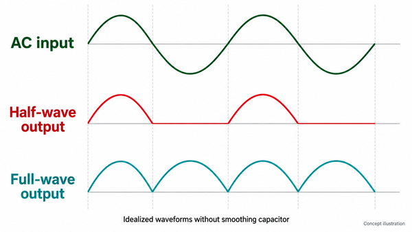
What does a rectifier diode do when the input alternates? In a simple series circuit, it passes one half-cycle and blocks the other. Arranging multiple devices into a full-wave circuit lets both input half-cycles deliver current through the load in the same direction.
Forward voltage is not a fixed 0.7 V. It changes with current, temperature and diode technology. A PN device also takes time to remove stored charge when switching from conduction to blocking, so a diode that suits a low-frequency supply may be unsuitable in a switching converter.
What Does the Rectifier Diode Symbol Mean?
The rectifier diode symbol identifies the anode and cathode; the straight bar marks the cathode. On many axial rectifiers, a band on the body identifies that same terminal. Match the symbol, package drawing and PCB footprint before assigning placement orientation. The rectifier diode diagram below relates the physical band to the two terminals.
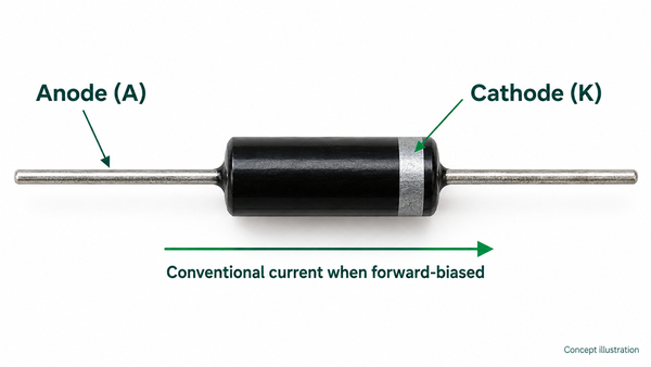
A rectifier diode number such as 1N4007 identifies an electrical device family, not a complete footprint specification. Supplier suffixes can change packaging and lead details. For SMD parts, confirm the manufacturer marking drawing rather than relying on a stripe convention alone. A readable polarity mark on the assembly drawing helps prevent a correct component being fitted backward.
How Do Half-Wave and Full-Wave Rectifier Circuits Differ?
A half-wave circuit uses one input half-cycle; a full-wave circuit uses both. In a single-phase rectifier diode circuit, the common full-wave choices are a four-diode bridge or a two-diode circuit with a center-tapped transformer secondary.
| Circuit | Diodes and source | Effect on the load |
|---|---|---|
| Half-wave | One diode with an AC source | One pulse per input cycle; larger gaps between charging pulses |
| Full-wave bridge | Four diodes; no center tap required | Two pulses per cycle; two diodes conduct in series in each current path |
| Center-tapped full-wave | Two diodes and a center-tapped secondary | Two pulses per cycle; each half-secondary conducts on alternate half-cycles |
How Many Diodes Are Used in a Bridge Rectifier?
A single-phase diode bridge rectifier uses four diodes. Its two alternating current paths each contain two conducting devices. This full wave bridge rectifier arrangement is convenient, but its two forward drops can be significant on a low-voltage rail.
In half wave rectifier diode selection, account for the interval in which the load receives no input energy. In full wave rectifier diode selection, consider which winding and diode pair carry current at each instant. A bridge rectifier diode must handle the charging pulses as well as the reverse-blocking interval.
A smoothing capacitor changes the current waveform: the diodes recharge it in pulses near the AC peaks. Diode peak current can therefore be much higher than the average load current. Ripple and inrush must be considered together, not solved by choosing a larger capacitor alone.
Which Rectifier Diode Types Suit Your Circuit?
Rectifier diode types differ in switching behavior and losses. Start with the circuit frequency and reverse voltage, then compare forward loss, leakage and package cooling.
| Technology | Typical fit | Main selection trade-off |
|---|---|---|
| Standard silicon PN rectifier | Low-frequency AC rectification | Low cost, but recovery may be too slow for a switching stage |
| Fast or ultrafast PN rectifier | Switching power conversion | Recovery charge and softness must be weighed against forward loss |
| Silicon Schottky rectifier | Low-voltage rails and fast switching | Low forward loss can be useful; reverse leakage rises with temperature |
| SiC Schottky rectifier | Higher-voltage, high-frequency conversion | Assess switching loss, conduction loss, cost and thermal design together |
Rectifier Diode vs Diode: What Is the Difference?
A rectifier is one use of a diode, not a separate opposite category. A small-signal switching diode is optimized for a different combination of current, capacitance and speed. A silicon rectifier diode cannot be replaced safely just because another diode has the same outline.
Rectifier Diode vs Schottky Diode
A Schottky rectifier diode is itself a rectifier. Compared with a conventional PN part, a silicon Schottky device often offers lower forward voltage and avoids minority-carrier storage recovery, but capacitive switching current still exists. Verify leakage at the expected temperature rather than assuming the lowest forward drop always produces the coolest design.
How Do You Distinguish Between Zener Diode and Rectifier Diode Functions?
A Zener diode is designed to operate in controlled reverse breakdown for voltage-reference or clamping tasks. A conventional rectifier normally works in forward conduction and reverse blocking. Swapping these roles without checking ratings can destroy the device or stop the circuit working.
Is 1N4007 a Rectifier Diode?
Yes. The 1N4007 rectifier diode is a common general-purpose silicon PN rectifier. A representative DO-41 version has a 1,000 V repetitive peak reverse-voltage rating and a 1 A average forward-current rating, with the current rating tied to specified mounting and temperature conditions.
For this DO-41 example, the 1 A condition uses 9.5 mm leads at 75°C ambient; maximum forward voltage is 1.1 V at 1 A under the stated electrical test conditions. These are device limits, not a promise that any small PCB can deliver a continuous 1 A DC output. Check the exact manufacturer’s datasheet, derating curve and rectifier circuit before substitution.
Its familiar part number does not make it the default for high-frequency rectification. Standard recovery, package dissipation and surge loading may matter more than its high reverse-voltage rating.
How Do You Select Rectifier Diode Ratings?
Select the device against the actual circuit waveform and temperature, not just the nominal supply voltage. The key ratings answer different questions.
| Parameter | What to check |
|---|---|
| VRRM | Worst repetitive reverse voltage, including circuit topology and expected transients; do not compare only with AC RMS voltage |
| IF(AV) | Average forward current under the specified cooling, waveform and temperature conditions |
| IFSM | Non-repetitive surge capability for the stated waveform and duration; not a continuous operating rating |
| VF | Forward loss at operating current and junction temperature |
| IR | Reverse leakage at operating voltage and temperature |
| trr and Qrr | Reverse recovery time and charge under comparable test conditions |
| Tj and thermal resistance | Allowable junction temperature and the actual path from device to board, enclosure or heatsink |
For a simple conduction-loss estimate, average the instantaneous product of diode voltage and current over time. Using VF × average current can be a first approximation when VF is represented appropriately; it does not include recovery or reverse-leakage losses. High-frequency designs need those additional terms.
Rectifier diode price also depends on package, qualification, voltage class and order quantity. A lower component cost is not a saving if it requires more cooling, a larger board or a different assembly process.
How Should Rectifier Diodes Be Laid Out on a PCB?
Give the rectifier a short current path, adequate copper and an unambiguous footprint. The board must carry pulsed current and remove heat without compromising insulation spacing.
For many control and low-power supply designs, FR4 printed circuit boards provide the required routing and mechanical support. Size conductors for the actual current waveform, copper thickness, allowable temperature rise and surrounding layout. Minimum fabrication line width is not a power-trace recommendation.
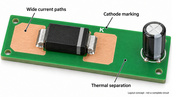
- Keep the bridge-to-reservoir-capacitor charging loop compact, including its return path.
- Use the specified land pattern and thermal-pad connection; do not add copper that bridges different electrical nodes.
- Separate hot rectifiers from electrolytic capacitors and temperature-sensitive circuitry where practical.
- Determine clearance and creepage from working voltage, environment and the applicable product requirements; do not use one spacing for every supply.
- Make the cathode orientation consistent across schematic, silkscreen, assembly drawing and placement data.
For higher-current paths, our heavy copper PCBs provide 4–10 oz copper options, subject to review of the complete design. Thicker copper can help current distribution and heat spreading, but it does not remove the diode’s junction-temperature limit. Wider conductors, pad geometry and soldering heat demand must be considered together.
How Do You Test a Rectifier Diode?
A multimeter’s diode mode can reveal a gross short or open circuit, but it does not prove the device will meet its high-voltage, current or switching ratings. Disconnect power, safely discharge stored energy and verify that no voltage remains before testing. Mains-connected supplies require qualified handling.
- With the isolated diode in forward bias, connect the red probe to the anode and the black probe to the cathode.
- Read the forward-voltage indication and compare it with the expected device technology and the meter’s test conditions.
- Reverse the probes. A normal reverse-blocking result usually appears as an over-range indication.
- If the result is ambiguous in circuit, isolate a terminal using an appropriate rework procedure; parallel paths can mislead the reading.
A near-zero reading both ways can indicate a short. Over-range both ways can indicate an open diode, but poor contact or insufficient meter test voltage can produce a similar result. Board-level diagnosis should also check solder joints, polarity and the surrounding circuit. A successful diode-mode reading does not replace a powered functional test under controlled conditions.
What Happens When a Diode Shorts in a Bridge Rectifier?
A shorted diode can create a heavy fault-current path during part of the AC cycle, potentially operating a fuse or damaging other components. Disconnect the supply and investigate the bridge and surrounding circuit before replacing parts; do not keep energizing the board to see whether the fault clears.
How Do We Build PCBs for Rectifier Circuits?
At EBest Circuit (Best Technology), we manufacture the PCB and assemble the specified components into your power-conversion circuit. Our PCB assembly services cover SMT, through-hole and mixed assembly, so an axial rectifier, an SMD diode and larger connectors can be incorporated into one board build.
We check incoming components against your BOM and support inspection and functional testing as part of the agreed assembly scope. Provide the exact diode part number, board files, polarity information and operating requirements so we can review the build consistently. Component selection remains tied to the approved design; we do not substitute a familiar diode number solely because the footprint fits.
For your next rectifier diode PCB project, send the fabrication files, BOM and assembly drawings to sales@bestpcbs.com. We can help connect the required copper construction, component mounting and assembly requirements in one manufacturing review.
You may also like







Tags: PCB Assembly, pcb design, power supply PCB, Rectifier Diode