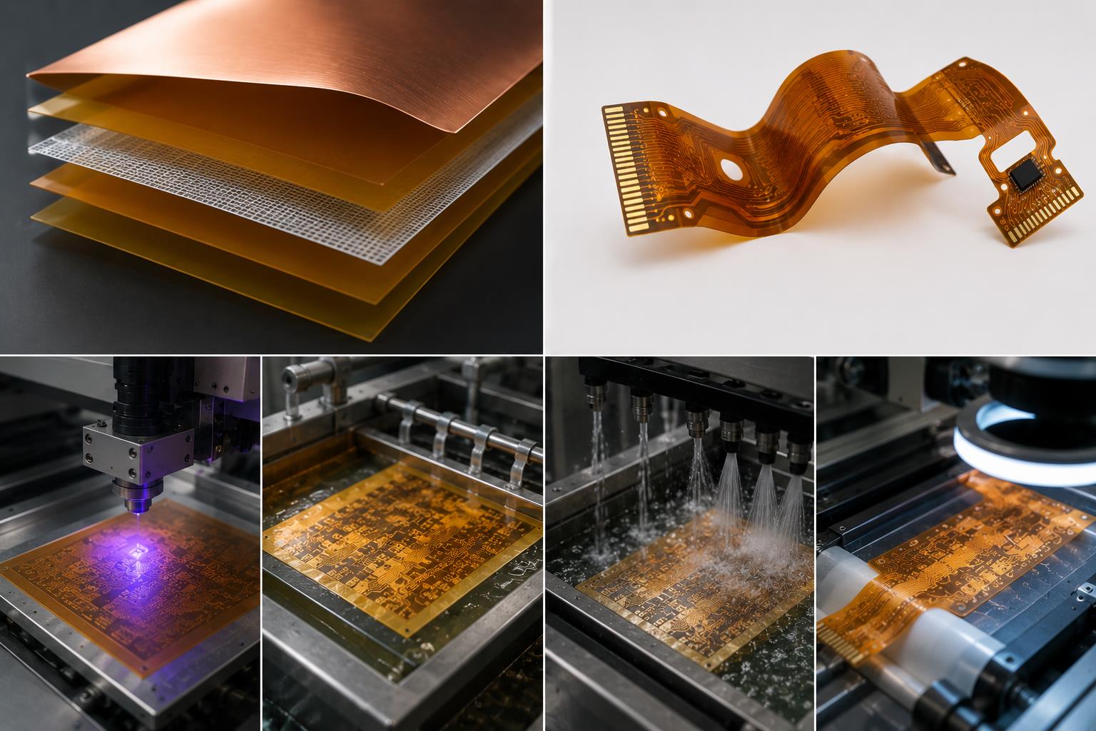
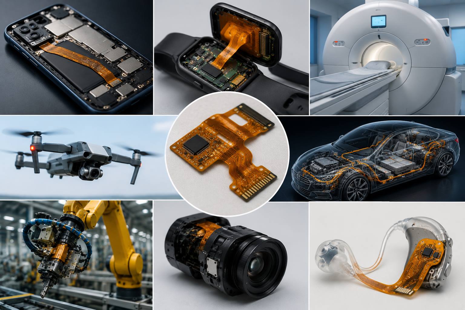
PCB manufacturing PCB manufacturing
Home > Blog

Flexible Printed Circuit: Materials, Types and Connections

September 22nd, 2026

A flexible printed circuit (FPC) is an electrical circuit built on a thin, bendable insulating film, usually polyimide, with patterned copper conductors. It can connect boards, carry components, or follow a three-dimensional enclosure where a rigid PCB will not fit.

Flexibility does not mean unlimited bending. A circuit folded during installation and one moving inside a hinge need different constructions. The materials, bend zone and connector ends must be designed together.
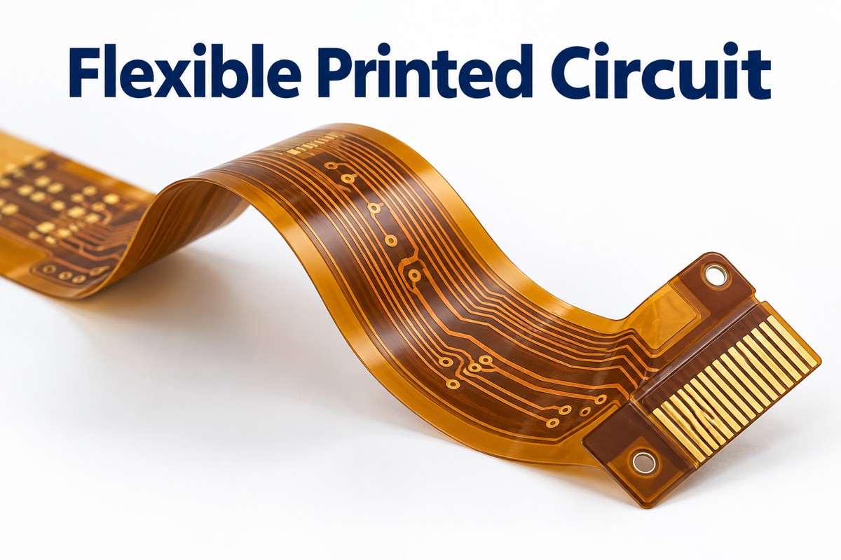
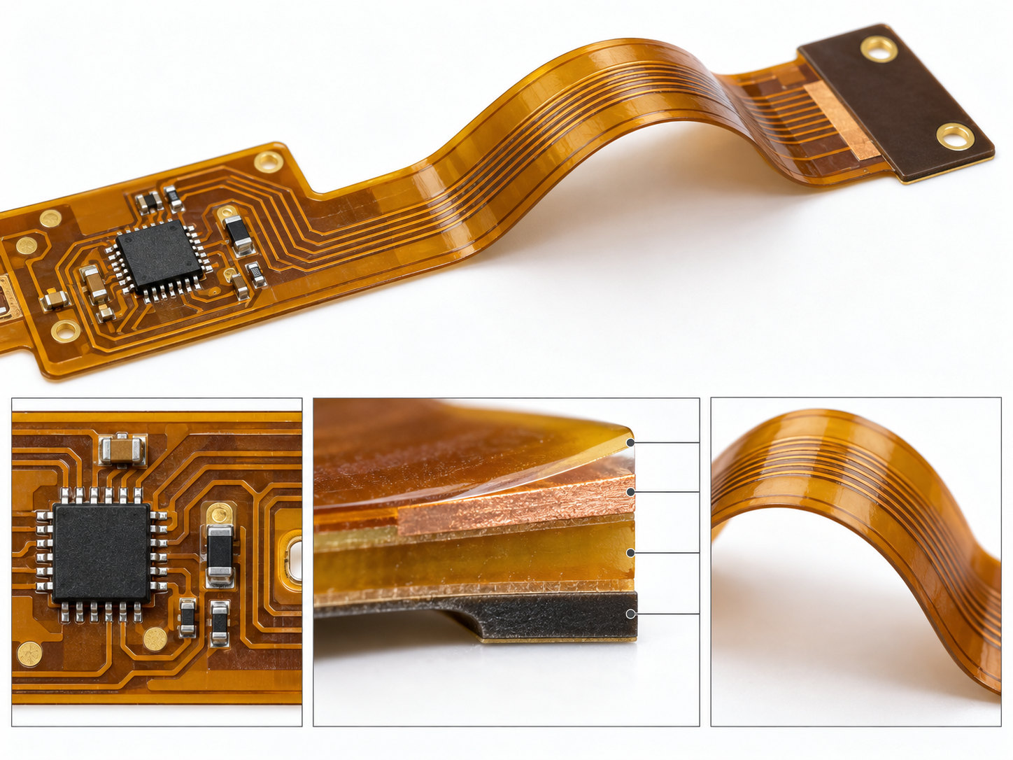
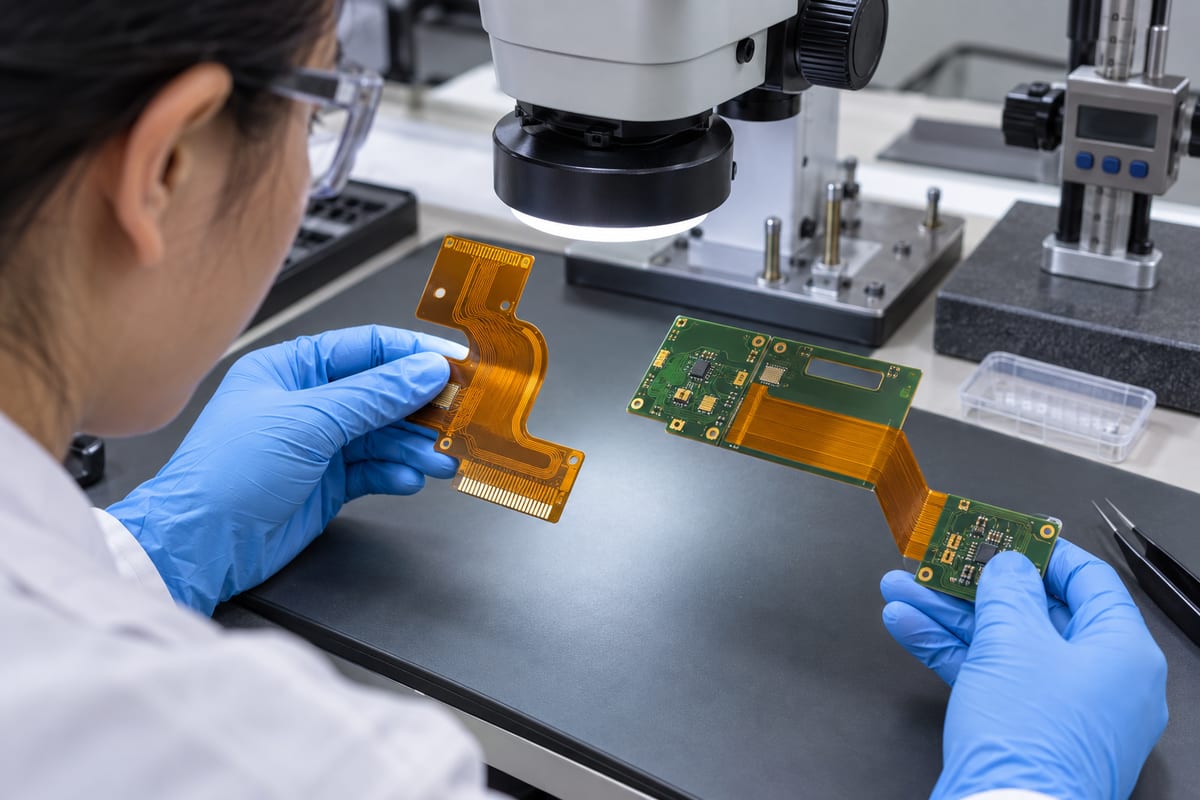
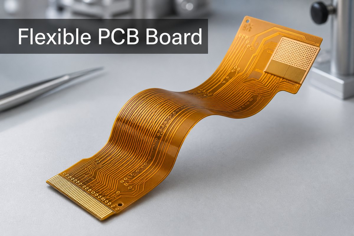
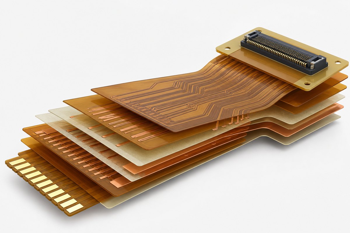
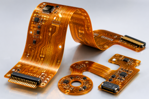
Amber flexible printed circuit with copper routing, a smooth bend and gold contact fingers

How Does a Flexible Printed Circuit Work?

An FPC carries power and signals through copper tracks just as a rigid PCB does; its thin film substrate lets those tracks follow a controlled bend. The copper is patterned into separate conductors, while insulating layers prevent contact between adjacent circuits.

A flexible printed circuit board can include pads, vias and mounted components, not just parallel wires. In a camera module, for example, one custom-shaped flex can route signals from the sensor board around a mechanical obstruction to the main board. Component locations remain supported while the connecting section bends.

What Are the Main Types of Flex Circuits?

The main constructions are single-sided, double-sided and multilayer flex; rigid-flex combines flexible interconnect sections with integrated rigid circuit sections.

Construction Copper structure Typical reason to choose it
Single-sided flex One conductive layer Simple routing with a thin bend region
Double-sided flex Two conductive layers, usually joined by plated holes More routing paths or a reference layer
Multilayer flex Three or more conductive layers Dense routing where a thicker stack is acceptable
Rigid-flex Rigid circuit sections integrated with flex layers Rigid component areas connected without separate cable connectors

Adding layers increases routing space but also changes bending stiffness. A multilayer design that fits a stationary enclosure is not automatically suitable for repeated movement.

Which Flexible Printed Circuit Board Material Should You Choose?

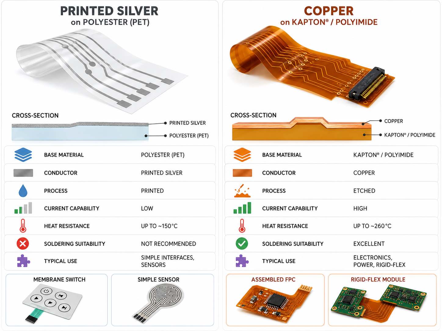
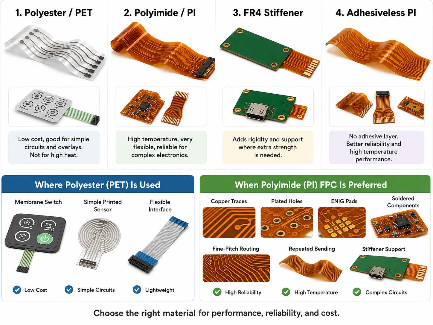
Polyimide with copper foil is a common choice for soldered FPC assemblies; the copper type, adhesive system and protective coverlay must then match the temperature and bending requirements.

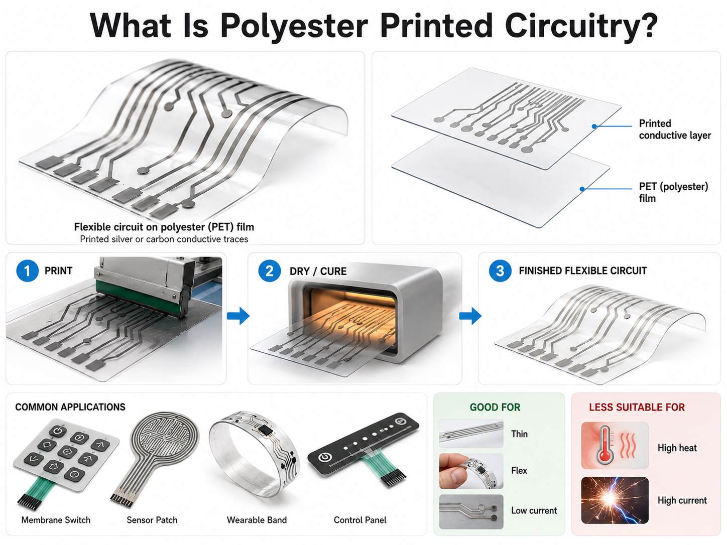
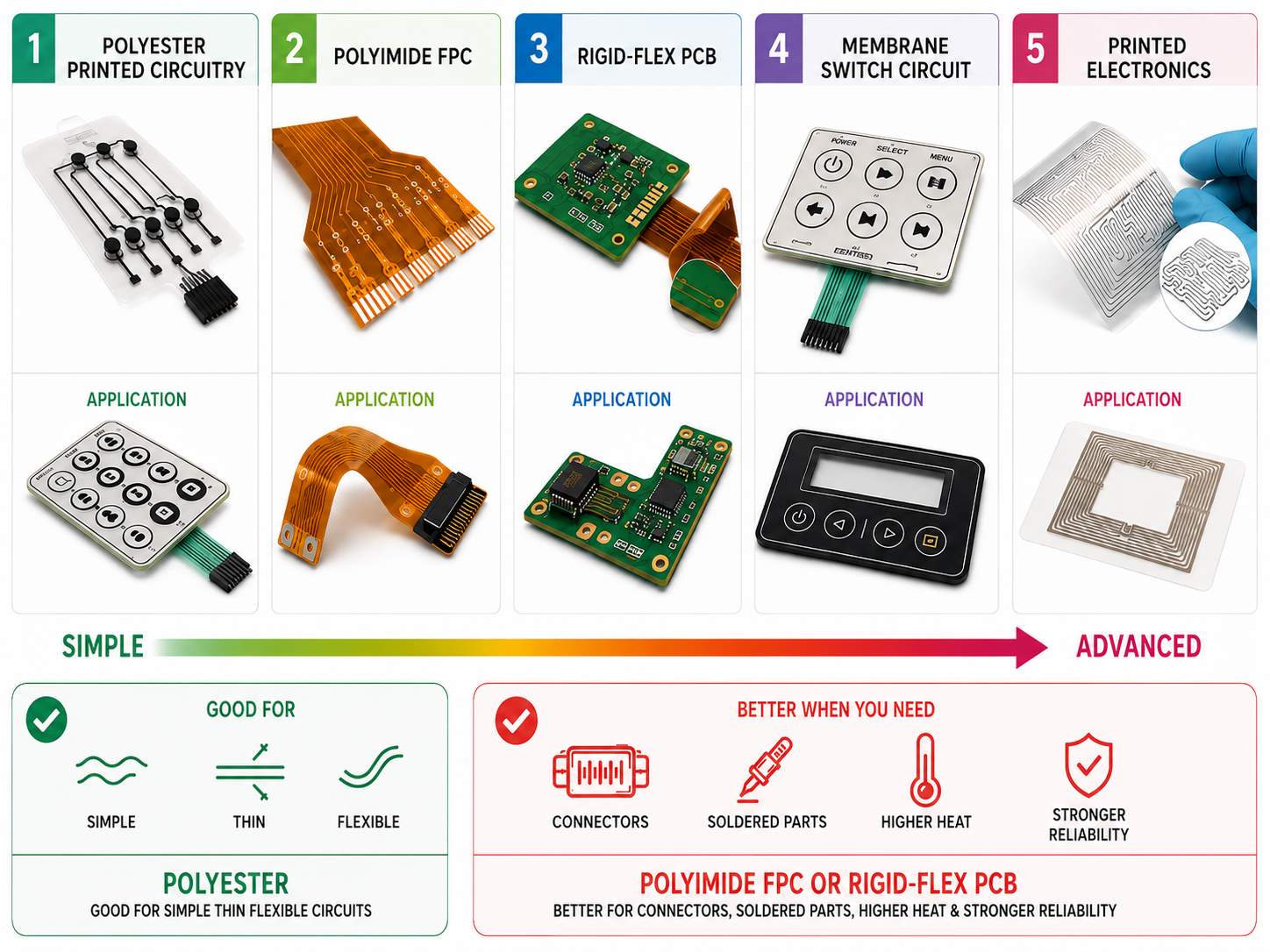
  • Base film: polyimide provides electrical insulation and tolerates the thermal processing used for many assembled flex circuits. Polyester is an alternative for suitable lower-temperature constructions, not an automatic replacement in a reflow-soldered design.
  • Copper: rolled-annealed copper is commonly evaluated for repeated flexing. Electrodeposited copper is also used, but foil grade and fatigue performance matter more than the abbreviation alone.
  • Laminate: adhesive-based constructions bond copper to film with an adhesive layer. Adhesiveless laminates remove that separate bonding layer from the copper-to-polyimide interface, helping reduce stack thickness.
  • Coverlay: a protective film and adhesive cover the tracks, with openings at solder pads and contacts.

For a concrete coverlay example, DuPont Pyralux LF7001 combines 13 µm adhesive with 13 µm polyimide, while LF0110 lists 25 µm for each. These are individual coverlay constructions, not finished FPC thicknesses.
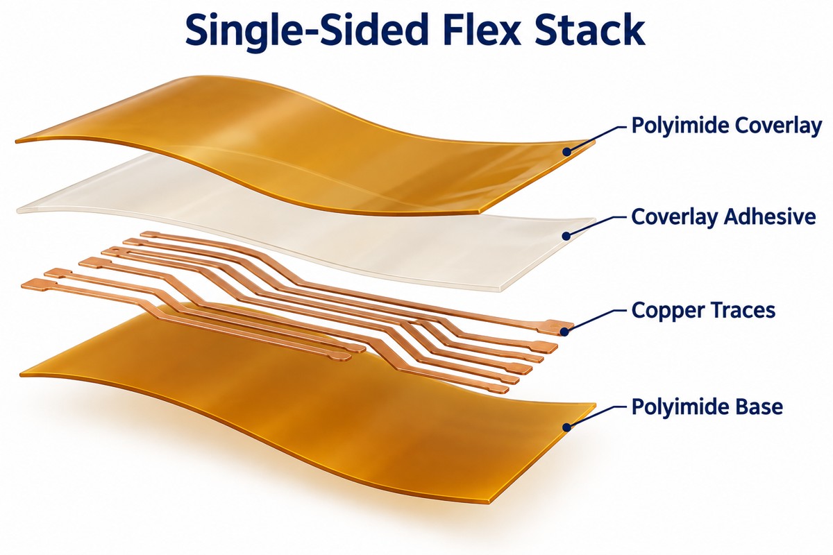
Exploded single-sided flex stack showing coverlay, coverlay adhesive, patterned copper and polyimide base

How Is an FPC Different from an FFC or a Rigid PCB?

An FPC has a custom circuit pattern, an FFC typically has parallel flat conductors, and a rigid PCB uses a substrate intended to stay rigid.

Feature FPC FFC Rigid PCB
Routing Custom tracks, branches and pads Usually parallel conductors Custom tracks, planes and vias
Form Custom outline with designed bend zones Usually a flat ribbon Fixed board shape
Component mounting Possible on supported areas Usually used as an interconnect cable Standard component platform

An FFC can be the simpler option for a straight connection between compatible sockets. Choose FPC when the circuit needs branching, an unusual outline, components or controlled routing. A flex board with a bonded stiffener is still not the same as an electrically integrated rigid-flex board.

How Do Static and Dynamic Bending Change the Design?

Static, or flex-to-install, circuits are bent into position and normally remain there; dynamic circuits must survive repeated movement without conductor fatigue.

For installation-only routing, define the formed shape, bend radius and assembly sequence. For dynamic routing, also specify the travel, cycle requirement, speed and operating environment. A hinge that passes one assembly bend has not demonstrated its service life.

  • Keep components, solder joints and plated holes outside the working bend zone.
  • Route conductors across the bend line rather than along it, and avoid abrupt changes in width.
  • Use smooth curves instead of creases; keep the moving section clear of sharp enclosure edges.
  • Evaluate the thinnest practical stack and suitable copper foil before adding layers or shielding.
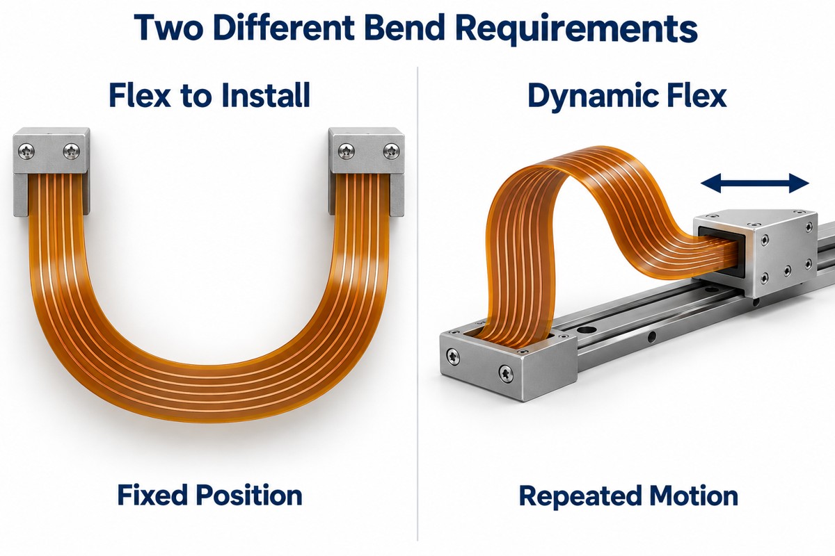
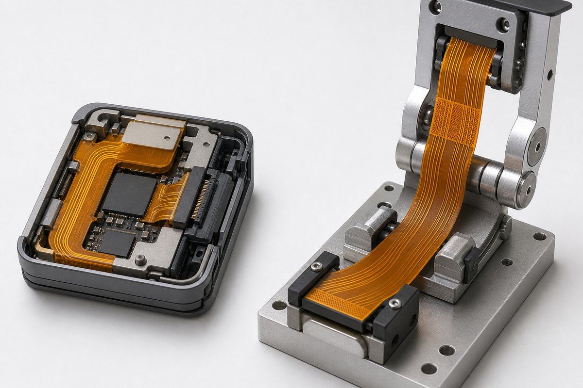
Comparison of a fixed installation bend and a rolling flex loop for repeated motion

How Is the Minimum Bend Radius Determined?

The minimum bend radius comes from the complete flex stack and required bend life, not from the polyimide thickness alone. Copper, adhesive and coverlay all contribute to the thickness and strain of the bend region.

For example, our rigid-flex DFM guide gives 6Ɨ composite thickness for single- and double-sided flex sections and 12Ɨ for sections with three or more copper layers. Under that guide’s construction assumptions, a 0.10 mm section at 6Ɨ gives a 0.60 mm radius. These are design guidelines, not a guarantee for every FPC or dynamic application.

Record the approved radius on the drawing and validate the actual construction at the required motion and temperature. Changing the copper thickness, shielding or coverlay after approval can invalidate the earlier bend assessment.

How Do You Match a Flexible Printed Circuit Connector?

Match the connector’s pitch, position count, contact side and specified FPC mating thickness before finalizing the tail drawing. Matching the number of contacts alone is not enough.

For example, Hirose FH12 is an FPC/FFC connector family offering 0.5 mm and 1 mm pitches. The exact part drawing determines the contact orientation and acceptable tail dimensions; the family name is not a complete interface specification.

  • Contact geometry: confirm finger width, pitch, exposed length and edge-to-contact dimensions.
  • Mating thickness: include the circuit, bonded stiffener and adhesive at the insertion area.
  • Contact side: verify whether the socket contacts the upper or lower face of the inserted tail.
  • Retention: allow access to the latch and keep cable pull or bending loads away from the connection.

A local PCB stiffener can support the tail and establish its mating thickness. Its edge should not force bending directly beside exposed contacts or solder joints.
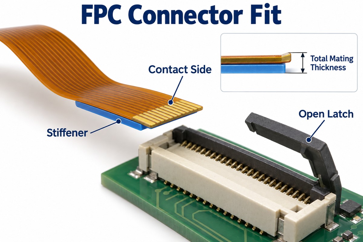
FPC tail, local stiffener and open ZIF connector with total mating thickness indicated

Flexible Printed Circuit Manufacturing Process

The flexible printed circuit manufacturing process patterns copper on a flexible laminate, forms any required interlayer connections, adds insulation and reinforcement, and tests the finished circuit.

  1. Prepare the laminate: select the specified copper-clad film and prepare the panel for imaging.
  2. Form the circuit: image and etch the copper tracks; drill and plate interconnections where the construction requires them.
  3. Protect the conductors: align and laminate coverlay with openings for pads and contacts.
  4. Complete exposed surfaces: apply the specified pad or contact finish and bond local stiffeners.
  5. Profile and test: cut the outline, inspect dimensions and check electrical continuity and isolation.

The exact sequence changes with layer count, via structure and finish. The etched FPC process explains copper pattern formation in more detail. Coverlay registration and adhesive flow deserve particular attention because a partly covered contact may not mate or solder correctly.

What Changes When Components Are Assembled on Flex?

Flex assembly needs support beneath the circuit during printing, placement and soldering so the thin panel stays flat and the joints remain unloaded.

  • Carrier or fixture: support the panel without obstructing pads or distorting the intended outline.
  • Moisture control: follow the laminate and assembly process requirements before thermal exposure; do not apply one universal baking recipe.
  • Reflow profile: qualify the temperature profile against the solder paste, components and complete flex material system.
  • Inspection: check solder joints and pad alignment, then use electrical or functional testing appropriate to the assembly.

After soldering, handle the assembly by supported areas. Pulling a loose tail to lift the board can transfer force into small pads or joints even when the soldering itself was acceptable.

Where Are Flexible Printed Circuits Most Useful?

FPCs are useful where a circuit must fit a narrow three-dimensional space, connect moving sections or reduce separate wire connections.

  • Cameras and displays: connect modules arranged on different planes.
  • Wearable devices: follow compact enclosure shapes and connect small component islands.
  • Medical instruments: route signals through constrained assemblies with application-specific material and reliability requirements.
  • Battery monitoring: distribute sensing connections across a cell arrangement without treating thin sensing traces as the main power bus.
  • Moving mechanisms: use a qualified dynamic flex section where the motion profile suits the construction.

For a flat assembly with ample space and no movement, a rigid PCB may be easier and less expensive. FPC is valuable when its geometry solves a real packaging or interconnection problem.

FAQ About Flexible Printed Circuits

Can an FPC be stretched?

Not like an elastic band. Conventional polyimide-and-copper flex is designed to bend, not stretch freely. Stretchable electronics require different materials or conductor geometries.

Can a torn flex circuit be repaired?

Some accessible traces can be repaired in controlled rework, but a repair changes local stiffness and may not survive repeated bending. Replacement is usually more appropriate for damaged moving sections or contacts that must fit a socket precisely.

Can flex carry high-speed signals?

Yes, with a designed transmission-line structure. Specify the impedance target, reference conductors, dielectric thickness and connector transition; bending and any change from solid to hatched shielding should be included in the assessment.

Is every amber flex circuit made from the same material?

No. Color does not identify the laminate grade, copper type or adhesive. The material specification and stackup are the reliable references.

What makes a custom FPC expensive?

More layers, complex outlines, poor panel utilization, fine features, multiple stiffeners and special materials can add cost. Compare quotations using the same construction and test requirements rather than board area alone.

How Can EBest Circuit Support Your Flex Circuit Project?

At EBest Circuit, we support flexible PCB and rigid-flex projects from prototype fabrication through production and assembly. Our PCB and PCBA services date back to 2006, and we can review the circuit, component sourcing and assembly requirements together.

For your flexible circuit project, send the Gerber or ODB++ data, stackup, bend drawing, connector part number and quantity to sales@bestpcbs.com. If assembly is required, include the BOM and placement data. We will review the material construction, reinforcement and manufacturing requirements before confirming a quotation.


You may also like

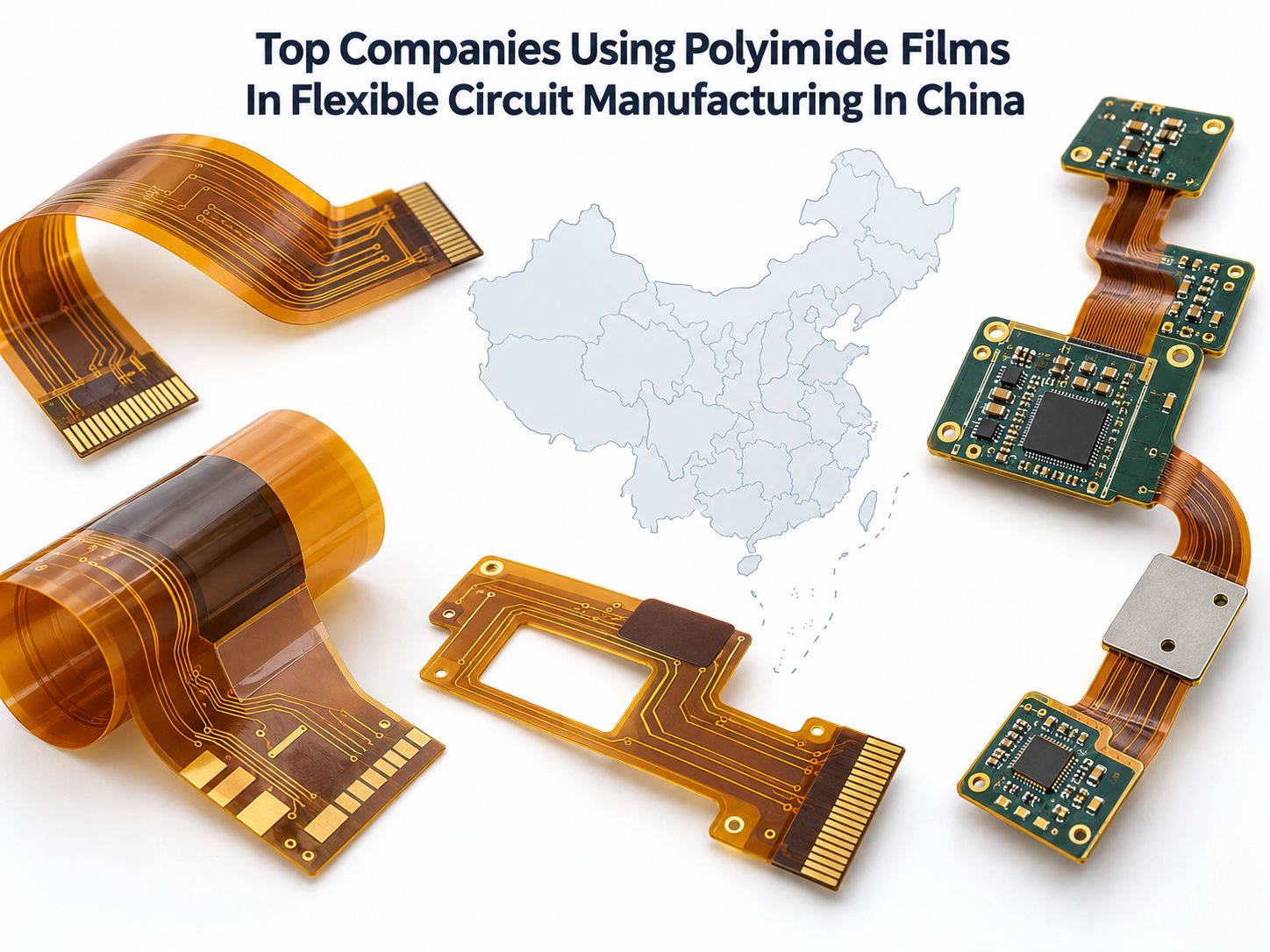
Top 10 Companies Using Polyimide Films in Flexible Circuit Manufacturing in China

September 17th, 2026

Polyimide flexible circuit companies use polyimide film in flexible circuit manufacturing because it combines a thin dielectric structure with heat resistance, electrical insulation, dimensional stability, and reliable bending performance. In China, PI films are used in single-sided FPCs, double-sided flex circuits, multilayer FPCs, rigid-flex boards, coverlays, stiffeners, and high-frequency flexible interconnects.

In supplier catalogs, terms such as polyimide PCB, polyimide flexible circuit, and polyimide flex circuits may describe overlapping FPC constructions.

The following 10 companies were selected based on their publicly documented flexible-circuit manufacturing capability, use of polyimide or modified polyimide materials, manufacturing presence in China, application coverage, engineering support, and quality certifications. The order is intended as a supplier comparison rather than a strict ranking by revenue or polyimide-film consumption.

Top companies using polyimide films in flexible circuit manufacturing in China

1. EBest Circuit

EBest Circuit manufactures polyimide flexible PCBs and rigid-flex boards for projects ranging from prototypes to production. Its flex capability covers PI substrates, coverlay, stiffeners, adhesiveless constructions, controlled impedance, HDI features, and rigid-flex stackups. PCB fabrication, DFM, component sourcing, PCBA, and testing can also be coordinated within one project. EBest’s published capability covers 1–10 layer FPCs and rigid-flex constructions for more complex interconnects.

Location: Shenzhen, Guangdong, China

Services:

  • Polyimide flexible PCB manufacturing
  • Multilayer FPC
  • Rigid-flex PCB manufacturing
  • PI coverlay and stiffeners
  • Controlled-impedance flex circuits
  • DFM and stackup review
  • FPC assembly and turnkey PCBA

Industries Served: Medical, automotive, aerospace, industrial control, communication, consumer electronics, and compact electronic devices

Key Differentiators:

  • PCB fabrication and PCBA coordinated in one workflow
  • DFM review covering bend zones, coverlay, stiffeners, stackup, and assembly
  • Support for both flexible and rigid-flex constructions
  • Prototype through production support

Certifications: ISO 9001, ISO 13485, IATF 16949, AS9100D, UL, RoHS, REACH

Polyimide flexible circuit structure with copper traces coverlay and bent flex section

2. Zhen Ding Technology / Avary Holding

Zhen Ding Technology operates a broad PCB platform covering FPC, rigid-flex, HDI, SLP, IC substrates, and modules. Its FPC products serve smartphones, notebooks, wearables, tablets, AR/VR devices, and other compact electronics. The group also develops high-frequency flexible interconnect technologies for advanced communication applications.

Location: Shenzhen, Huai’an, Qinhuangdao, and other mainland China production sites

Services:

  • High-volume flexible PCB manufacturing
  • Modified-polyimide flexible circuits
  • LCP flexible circuits
  • Rigid-flex PCB
  • HDI and SLP manufacturing
  • FPC module assembly and testing

Industries Served: Smartphones, notebooks, tablets, wearables, AR/VR, communication equipment, automotive electronics, smart home products, and medical devices

Key Differentiators:

  • Large-scale FPC manufacturing footprint
  • High-frequency flexible-circuit capability
  • FPC fabrication combined with module assembly
  • Broad PCB portfolio covering FPC, HDI, SLP, rigid-flex, and substrates

Certifications: ISO 9001, IATF 16949, IECQ QC 080000, ISO 14001, ISO 45001, ISO 50001, UL, CQC

3. DSBJ / MFLEX

MFLEX, part of DSBJ, manufactures flexible printed circuits on polyimide dielectrics with copper conductors and supports PI, modified PI, LCP, adhesive, and adhesiveless material systems. Its China manufacturing footprint includes facilities in Suzhou and Yancheng, with capabilities extending from FPC fabrication to component and module assembly.

Location: Suzhou and Yancheng, Jiangsu, China

Services:

  • Single-sided to multilayer FPC
  • PI and modified-PI flexible circuits
  • Adhesive and adhesiveless structures
  • Rigid-flex constructions
  • HDI flex and microvia processing
  • FPC component assembly
  • Module assembly and functional testing

Industries Served: Smartphones, notebooks, tablets, wearables, health electronics, IoT, smart home products, consumer electronics, and new-energy vehicles

Key Differentiators:

  • Dedicated FPCB fabrication and FPCA facilities in China
  • PI, mPI, and LCP material support
  • Static and dynamic flex capability
  • Fabrication, component assembly, and module integration

Certifications: ISO 14001, ISO 50001

Flexible circuit manufacturing and inspection in a modern China electronics factory

4. Shenzhen Kinwong Electronic Co., Ltd.

Kinwong manufactures single-sided, double-sided, and multilayer flexible PCBs with published capability up to six flex layers. Its FPC platform includes roll-to-roll processing, 50 μm microvias, 35/35 μm line/space, SMT, ICT, FCT, assembly, and 5G FPC simulation and testing.

Location: Shenzhen, Guangdong, China

Services:

  • Single-sided and double-sided FPC
  • Multilayer FPC up to six flex layers
  • Rigid-flex PCB
  • Roll-to-roll FPC production
  • Microvia and fine-line processing
  • Controlled-impedance flex
  • SMT, ICT, FCT, and assembly

Industries Served: Automotive, medical, industrial control, smart terminals, wearables, consumer electronics, telecom, and 5G products

Key Differentiators:

  • Roll-to-roll flexible-circuit production
  • Fine-line and microvia capability
  • FPC fabrication combined with assembly and testing
  • 5G FPC simulation, manufacturing, and testing support

Certifications: ISO 9001, ISO 13485, IATF 16949, ISO 14001, ISO 50001, ISO 45001, IECQ QC 080000, ISO/IEC 27001, ISO/IEC 17025

5. Suntak Technology Co., Ltd.

Suntak explicitly states that its flexible PCBs use polyimide substrates for three-dimensional dynamic wiring. Its published FPC capability includes structures below 0.2 mm, repeated bending, and 50 μm-level dense routing for mobile, automotive, medical, and communication applications.

Location: Shenzhen, Guangdong, China

Services:

  • Polyimide FPC manufacturing
  • Single-sided and multilayer flexible PCB
  • Rigid-flex PCB
  • Fine-line FPC
  • Thin flexible circuits
  • High-density flexible interconnects

Industries Served: Mobile phones, wearables, automotive electronics, laptops, tablets, 5G optical communication, medical devices, and consumer electronics

Key Differentiators:

  • Documented PI-based FPC production
  • Thin FPC structures
  • Fine routing for compact flex applications
  • Dedicated Shenzhen FPC manufacturing

Certifications: ISO 9001, IATF 16949, AS9100, ISO 13485, ISO 14001, ISO 45001, ISO/IEC 27001, IECQ QC 080000, SA8000, RBA

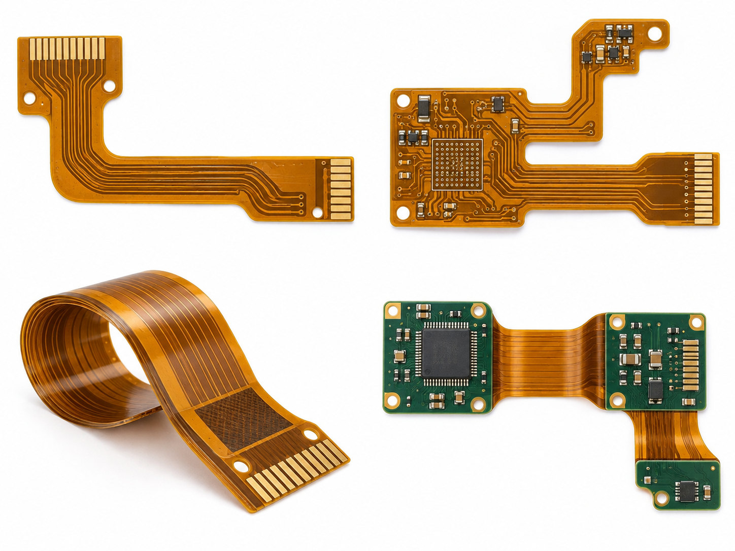
Single-sided double-sided multilayer and rigid-flex polyimide flexible circuit examples

6. JLCPCB

JLCPCB provides standardized polyimide flex PCB manufacturing through its online ordering platform. Its published FPC capability covers one-, two-, and four-layer flex circuits, 25 μm and 50 μm PI dielectric options, adhesive and adhesiveless PI, localized stiffeners, and controlled-impedance-compatible structures.

Location: China

Services:

  • 1–4 layer flexible PCB
  • Polyimide base material
  • Adhesiveless PI FPC
  • PI, FR4, and stainless-steel stiffeners
  • Coverlay processing
  • FPC prototyping
  • PCB assembly support

Industries Served: Consumer electronics, wearables, cameras, medical electronics, automotive electronics, education, startups, and product development

Key Differentiators:

  • Online instant quotation and ordering
  • Published standard PI stackups
  • 25 μm and 50 μm PI options
  • Strong fit for prototype and small-batch FPC orders

Certifications: ISO 9001, IATF 16949, ISO 13485, ISO 14001, UL, RoHS, REACH, ISO/IEC 27001

7. PCBWay

PCBWay supports flexible PCB and rigid-flex manufacturing with polyimide available as a primary flexible base material. Its online FPC configuration supports multilayer designs, PI stiffeners, coverlay, controlled impedance, multiple thicknesses, and custom flex constructions.

Location: Hangzhou, Zhejiang, China

Services:

  • Polyimide flexible PCB
  • Multilayer FPC
  • Rigid-flex PCB
  • Custom FPC stackups
  • PI stiffeners
  • Controlled impedance
  • PCB assembly and component sourcing

Industries Served: Medical electronics, robotics, automotive, consumer products, industrial equipment, communication devices, and R&D projects

Key Differentiators:

  • Broad online FPC configuration options
  • Polyimide and other flexible material choices
  • Custom multilayer FPC support
  • Flexible PCB, rigid-flex, assembly, and prototyping services

Certifications: ISO 9001, ISO 13485, IATF 16949, UL, RoHS, REACH, CE

8. Capel / Shenzhen Kaboer Technology Co., Ltd.

Capel is the brand used by Shenzhen Kaboer Technology for flexible PCB, rigid-flex, HDI, and PCBA manufacturing. Its current process capability lists flexible circuits from single-sided through multilayer constructions, rigid-flex boards, PI material processing, fine-line routing, impedance control, and IPC-6013 acceptance support.

Location: Shenzhen, Guangdong, China

Services:

  • Polyimide FPC manufacturing
  • Multilayer flexible PCB
  • Rigid-flex PCB
  • PI coverlay and stiffeners
  • Controlled impedance
  • HDI and fine-line flex
  • SMT assembly and PCBA

Industries Served: Medical devices, automotive, aerospace, UAVs, IoT, industrial control, telecommunications, AI hardware, EVs, and consumer electronics

Key Differentiators:

  • Wide published flex and rigid-flex layer range
  • Fine-line flex capability
  • FPC fabrication plus assembly support
  • Support for IPC-6013 flexible-board acceptance

Certifications: ISO 9001, ISO 14001, ISO 45001, IATF 16949, ISO 13485, GJB9001C, UL

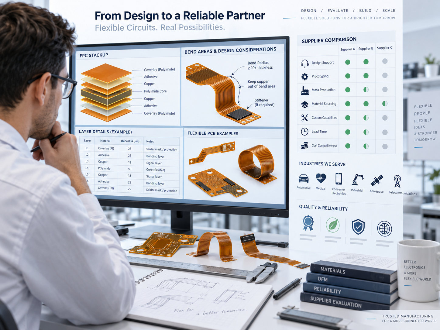
Engineer evaluating flexible circuit stackup bend areas and supplier capabilities

9. XiangYuan Insulation Materials Co., Ltd.

XiangYuan differs from most companies on this list because its operations span polyimide film, FCCL flexible copper-clad laminate, and finished FPC manufacturing. This gives the company direct involvement in the flexible-circuit material chain rather than only PCB fabrication.

Location: Tianjin, China, with additional production bases in Jiangxi, Shenzhen, Zhuhai, and other locations

Services:

  • Polyimide film manufacturing
  • FCCL manufacturing
  • Adhesive and adhesiveless flexible materials
  • Single-sided FPC
  • Double-sided FPC
  • Flexible-circuit material development

Industries Served: Consumer electronics, communication equipment, computers, aerospace, military electronics, optoelectronics, and new-energy applications

Key Differentiators:

  • PI film, FCCL, and FPC within the same product chain
  • Direct polyimide-film manufacturing
  • 12.5 μm, 25 μm, and 50 μm PI film options
  • Strong fit where flexible material sourcing is important

Certifications: ISO 9001, ISO 14001, UL

10. Honflex Electronics

Honflex Electronics focuses heavily on flexible circuit manufacturing and serves high-volume electronics applications including smartphones, displays, wearables, automotive electronics, new-energy systems, and other compact products. Its FPC technology portfolio includes multilayer flex, fine-line structures, and high-frequency flexible interconnects.

Location: Xiamen, Fujian, China

Services:

  • Flexible PCB manufacturing
  • Multilayer FPC
  • Rigid-flex PCB
  • MPI high-frequency flexible circuits
  • HDI FPC
  • Fine-line flexible circuits
  • Automotive FPC and battery interconnect products

Industries Served: Smartphones, notebooks, tablets, displays, wearables, automotive electronics, new-energy vehicles, robotics, industrial electronics, medical products, and smart home devices

Key Differentiators:

  • FPC-focused manufacturing platform
  • High-frequency flexible-circuit capability
  • Fine-line and HDI FPC structures
  • Dedicated automotive and new-energy flex products

Certifications: ISO 9001, IATF 16949, IECQ QC 080000, ISO 14001, ISO 45001, ISO 50001, ISO/IEC 27001, UL

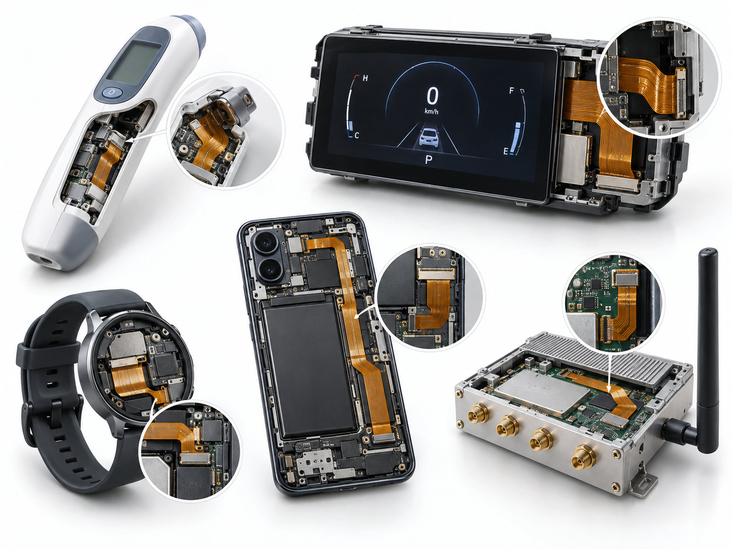
Medical automotive wearable consumer electronics and communication products using flexible circuits

FAQs

1. Why is polyimide film widely used in flexible circuit manufacturing? Polyimide combines flexibility, heat resistance, electrical insulation, and dimensional stability. It can tolerate PCB fabrication and assembly temperatures while remaining thin enough for flex and rigid-flex structures.

2. What polyimide thickness is commonly used in flexible PCBs? Common PI base-film thicknesses include approximately 12.5 μm, 25 μm, and 50 μm. The final thickness depends on the FPC stackup, bend radius, copper construction, and mechanical requirement.

3. What is the difference between adhesive and adhesiveless polyimide FPC? Adhesive FPC uses a separate bonding layer between copper and polyimide. Adhesiveless material removes that separate adhesive layer, reducing the dielectric build and making it useful for thinner or repeatedly flexed constructions.

4. Can Chinese FPC manufacturers provide both fabrication and assembly? Yes. Several companies on this list combine flexible-circuit fabrication with component assembly, testing, or module integration.

5. What should I send a polyimide FPC manufacturer for quotation? Send the Gerber or ODB++ files, stackup, PI material requirement, copper weight, finished thickness, bend radius or flex-cycle requirement, coverlay, stiffener details, surface finish, impedance targets, quantity, and BOM/CPL files when assembly is required.

Looking for a Polyimide FPC Manufacturer in China?

Choosing a flexible circuit supplier is not only about whether the factory can process polyimide. PI thickness, copper type, adhesive system, coverlay, bend-zone layout, stiffener design, impedance, and assembly conditions all affect the finished FPC.

EBest Circuit supports polyimide FPC and rigid-flex PCB fabrication, DFM review, component sourcing, and PCBA for prototype and production projects. If you are developing a new flexible circuit, send your Gerber files, stackup, bend requirements, and assembly specifications to sales@bestpcbs.com for engineering review.

You may also like

FPC Manufacturer UK: Which Supplier Fits Your Project?

September 10th, 2026

FPC manufacturer UK searches lead to companies with very different strengths. Some operate PCB factories in the UK, some specialise in flexible circuits for demanding applications, and others combine local customer support with offshore production. The most useful comparison is therefore not a long directory. It is a clear view of what each manufacturer actually produces and which type of project it suits.

This guide compares five UK manufacturers, shows published FPC process capabilities, and explains where an offshore option may fit. EBest Circuit (Best Technology) manufactures flexible and rigid-flex PCBs for UK customers that need engineering communication, scalable production, and optional assembly through one technical contact. To discuss a released design, email sales@bestpcbs.com with your Gerber or ODB++ data, stack-up, quantity, and application details.

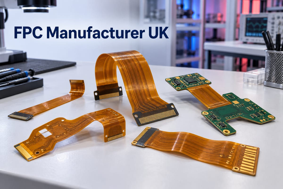
FPC manufacturer UK
Flexible and rigid-flex PCB examples for UK manufacturing projects.

Which FPC Manufacturers Serve UK Projects?

The five companies below have identifiable UK manufacturing operations and publicly describe flexible or rigid-flex PCB capability. They are not ranked because their strongest applications are different.

Manufacturer UK operation Best suited to
GSPK Circuits North Yorkshire General flex, rigid-flex, and specialist PCB projects
Exception PCB Tewkesbury Complex multilayer, HDI, and advanced rigid-flex builds
Merlin Flex Hartlepool Dedicated flex manufacturing and added-value assembly
Amphenol Trackwise Stonehouse Long-length FPCs for aerospace, EV, medical, and industrial systems
Cambridge Circuit Company Cambridge In-house prototypes and fast-turn flex or flex-rigid boards

GSPK Circuits is a broad UK PCB manufacturer rather than a flex-only company. Its North Yorkshire facility produces flex and rigid-flex boards alongside HDI, RF, IMS, and other specialist constructions. GSPK is relevant when a project needs conventional or complex flexible circuitry from a manufacturer with a published process table and UK production.

Exception PCB manufactures flex and rigid-flex PCBs at its Tewkesbury facility. Its published capability extends to high-layer-count rigid-flex, fine features, laser microvias, and filled vias. It is a stronger candidate when the flex construction is part of a dense multilayer or HDI design rather than a simple flexible interconnect.

Merlin Flex is the dedicated flexible-circuit business within Merlin PCB Group. It manufactures flexible and flex-rigid PCBs in Hartlepool and also provides component assembly. Its specialist focus makes it relevant to customers who want a UK source centred on flex technology rather than a general PCB supplier that also offers flex.

Amphenol Trackwise occupies a distinct position. Its continuous roll-to-roll process produces multilayer flexible circuits that can extend far beyond conventional panel lengths. It is particularly relevant when an FPC replaces a large wiring harness in aerospace, electric-vehicle battery systems, medical equipment, or industrial machinery.

Cambridge Circuit Company offers in-house UK production of multilayer, flex, flex-rigid, plated-through-hole, and single-sided boards. The company emphasises prototype and fast-turn manufacturing, making it a practical option for development teams that prioritise short feedback loops and local production.

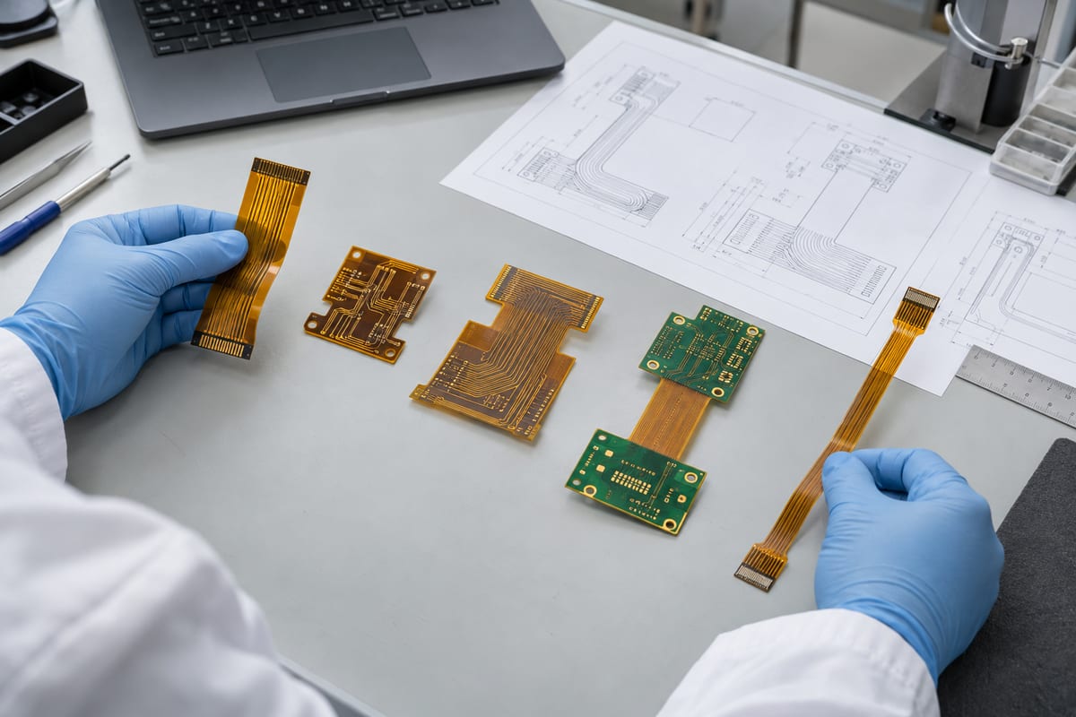
FPC manufacturer UK
Comparing different flexible and rigid-flex constructions before selecting a manufacturing source.

How Do UK FPC Suppliers Differ by Application?

The best supplier depends on where the FPC will operate and what the finished product demands from it. UK manufacturers position their capabilities around different application markets.

Supplier strengths by application:

Application Relevant UK suppliers Best match
Aerospace and defence Trackwise, Exception PCB, Graphic PLC Long harness replacement or complex rigid-flex avionics
Automotive and EV Trackwise Battery-pack and cell-control interconnects
Medical equipment Trackwise, Graphic PLC Miniature interconnects and high-reliability flex-rigid
Industrial and scientific GSPK, Trackwise Conventional flex or extended power and signal routing
Consumer and wearable Merlin Flex, Cambridge Circuit General flex production and fast prototypes

Trackwise is most distinctive when circuit length or harness replacement drives the design. Exception PCB and Graphic PLC better match dense, high-reliability rigid-flex assemblies. GSPK covers a broader range of conventional and specialist flex builds, while Merlin Flex and Cambridge Circuit Company provide more general flex manufacturing or prototype routes. The last two matches are based on published manufacturing scope rather than a stated specialisation in consumer or wearable products.

Application is the first filter, not the final decision. After identifying suppliers active in the relevant market, compare the actual circuit construction with their published process capabilities.

Which Flex and Rigid-Flex PCBs Can UK Suppliers Produce?

UK manufacturers cover more than one type of flexible circuit. The construction should be matched to the product rather than selected from the name alone.

  • Single-sided FPCs: Suit simple connections, sensors, membrane-style interfaces, and low-density routing.
  • Double-sided FPCs: Provide more routing space and plated interconnection while remaining thinner and simpler than most multilayer constructions.
  • Multilayer FPCs: Support higher connection density, shielding, controlled routing, or a larger number of conductors in limited space.
  • Rigid-flex PCBs: Integrate rigid component areas and flexible interconnects into a single manufactured structure. They can remove separate cables and connectors, but the transition between rigid and flexible areas adds manufacturing complexity. Exception PCB, GSPK, Merlin Flex, and Cambridge Circuit Company all publicly present rigid-flex or flex-rigid capability.
  • Dynamic-flex circuits: Are designed for repeated movement rather than a single installation bend. They require greater attention to copper type, grain direction, bend radius, layer balance, conductor routing, and the position of coverlay or stiffener transitions. A supplier that can manufacture an FPC is not automatically the right source for a circuit expected to complete thousands or millions of bending cycles.
  • Long-length FPCs: Form a more specialised category. Trackwise uses a continuous manufacturing process for circuits that exceed standard panel dimensions. This construction is relevant when a product designer wants to replace a long cable harness with a thin, repeatable printed interconnect.

What Manufacturing Capabilities Do UK FPC Suppliers Offer?

GSPK publishes standard and advanced flex and rigid-flex manufacturing values. The figures below show what one established UK manufacturer states it can support; they should not be treated as universal limits for every UK supplier.

Capability Standard Advanced
Flex layers 2 8
Rigid layers 10 14
Overall thickness 0.20–3.20 mm 0.06–5.00 mm
Maximum board size 266.7 Ɨ 430 mm 350 Ɨ 500 mm
Inner track/gap, 17 µm copper 90 µm 50 µm
Outer track/gap, 17 µm base copper 100 µm 75 µm
Copper options 0.5 oz and 1 oz Up to 2 oz
Stiffener options Coverlay, FR-4, prepreg Aluminium also available

GSPK also lists HASL, lead-free HASL for single-sided FPCs, ENIG, and OSP for constructions without stiffeners. Larger board sizes and higher flex-layer counts may be available after review.

Three practical conclusions can be drawn from this table. First, UK manufacturing is not limited to simple one- or two-layer flexible circuits; GSPK publishes an advanced flex capability of eight layers and rigid sections up to fourteen layers. Second, fine-line capability changes with copper thickness and whether the conductor is on an inner or external layer, so a single ā€œminimum trackā€ number can be misleading. Third, layer count, thickness, board size, copper, finish, and stiffener requirements must be evaluated as one construction. A design cannot assume that every advanced limit can be combined simultaneously.

FPC manufacturer UK
Inspecting flexible circuitry, coverlay features, connector areas, and rigid-flex transitions.

Which UK FPC Suppliers Support Aerospace and High-Reliability Applications?

For aerospace and high-reliability work, supplier fit becomes clearer when companies are compared by the manufacturing capability they publicly associate with demanding applications. The five examples below offer different strengths; they should not be treated as interchangeable.

UK manufacturer Relevant strength Projects it may suit
Amphenol Trackwise Roll-to-roll long FPC Aircraft harness replacement
Exception PCB 24-layer rigid-flex and HDI Dense avionics and defence boards
Graphic PLC Flex-rigid and advanced vias Avionics, space, and medical
GSPK Circuits UK specialist flex production Defence and controlled UK supply
PW Circuits Flex-rigid and Class 3 High-reliability, mid-volume builds

Amphenol Trackwise is the most distinctive choice when circuit length is the central problem. Its continuous roll-to-roll process supports working panels up to 100 metres long and 630 mm wide, with up to eight copper layers for prototypes and four for production, subject to construction. Trackwise states that it has manufactured a flexible multilayer circuit longer than 72 metres. This capability is relevant when a printed circuit replaces wiring across an aircraft wing, vehicle battery system, or other large structure; it adds little value to an ordinary short FPC.

Exception PCB is more relevant when high reliability is combined with dense rigid-flex construction. Its published capability includes up to 24 rigid-flex layers, up to 12 flex layers, track and gap down to 60 µm on its advanced process, laser microvias down to 75 µm, and copper or resin via filling. These features make it a stronger candidate for compact assemblies in which the rigid section carries HDI components while the flex section replaces separate interconnects.

Graphic PLC positions its UK manufacturing around high-technology PCBs for avionics, space, security, medical, and other high-reliability sectors. Its stated strengths include flex-rigid construction, HDI, blind and buried vias, filled and stacked vias, and sequential build-up. It may therefore be relevant when the project needs both flex-rigid integration and advanced via structures.

GSPK Circuits offers a broader specialist-PCB route from its North Yorkshire facility. Its published material identifies defence as a sector that can benefit from controlling processes such as ENEPIG internally rather than sending boards to an external subcontractor. This may matter when the customer values UK production and a shorter, more visible manufacturing chain alongside flex or rigid-flex capability.

PW Circuits publicly lists single- and double-sided flex, multilayer flex-rigid, specialist material experience, and IPC 6013 Class 3 among its capabilities and approvals. It may suit customers that need UK prototype-to-mid-volume production and requirements associated with more demanding flexible-circuit acceptance.

The useful distinction is not that all five companies serve ā€œhigh reliability.ā€ Trackwise solves unusual circuit-length problems; Exception PCB and Graphic address complex constructions; GSPK offers broad specialist production with UK process control; and PW Circuits combines flex capability with demanding-board approvals. The application and released construction determine which strength is relevant.

FPC manufacturer UK
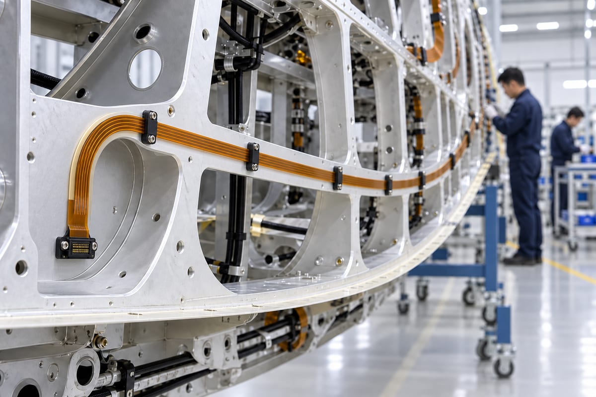
An illustrative long flexible circuit routed through a large high-reliability equipment structure.

UK Manufacturing or Offshore Production: Which Model Fits?

The right model depends on what the project needs at its current stage.

UK manufacturing is a stronger fit when:

  • local production or supply-chain visibility is required;
  • early revisions need rapid engineering feedback;
  • an unusual construction benefits from close technical discussion;
  • low-volume or urgent prototypes are the immediate priority.

Offshore production is a stronger fit when:

  • the design is stable and volumes are expected to grow;
  • production cost is important;
  • multilayer flex, rigid-flex, sourcing, and PCBA need one supply route;
  • international logistics can be planned into the schedule.

A hybrid route can fit when:

  • a UK factory supports development or urgent prototypes; and
  • a qualified offshore factory handles repeat production.

The choice is not ā€œUK qualityā€ versus ā€œoffshore cost.ā€ Whichever model is used, materials, stack-up, copper type, coverlay openings, stiffeners, bend regions, finish, and testing must remain controlled. Otherwise, the prototype and production board may look similar while behaving differently.

How Can EBest Circuit Support UK FPC Projects?

EBest Circuit (Best Technology) is an offshore option for UK customers that need flexible or rigid-flex PCB production beyond a local prototype order. Its role is to give the customer one technical route from a released design to repeat manufacturing, while keeping the construction agreed during quotation visible throughout the project.

Support for UK projects centres on four practical outcomes:

  • Direct technical communication: Questions about the stack-up, polyimide, copper, coverlay, stiffeners, bend areas, and finish are resolved with the manufacturing team before production. This reduces the risk of commercial messages being passed between the customer, a broker, and an unidentified factory.
  • A controlled move from prototype to production: The agreed materials, layer structure, flex thickness, openings, and test requirements can remain part of the same manufacturing definition as quantities increase. The customer does not need to restart the technical discussion simply because the project moves beyond its first build.
  • Offshore production with a defined scope: UK customers can use EBest Circuit when local production does not provide the required commercial fit, production capacity, or flex and rigid-flex process range. The value comes from matching the released construction to an established process, not from choosing an offshore quotation on price alone.
  • Optional fabrication-to-assembly continuity: When the project includes connectors or mounted components, sourcing and PCBA can follow the same technical handoff. When only bare FPCs are required, the project can remain fabrication-only without an unnecessary assembly package.

The manufacturing capabilities discussed earlier in this article provide the technical basis for this support. EBest Circuit confirms the usable combination for each design rather than assuming that separate maximum values for layers, copper, thickness, and fine features can all be applied at once.

Send your Gerber or ODB++ data, drill files, stack-up, mechanical drawing, target quantity, and bending conditions to sales@bestpcbs.com. EBest Circuit can then confirm whether the design fits its manufacturing scope and whether bare-board production or a combined fabrication-and-assembly route is more appropriate.

FAQs About FPC Manufacturer UK

Are all companies appearing as UK FPC manufacturers producing boards in the UK?

No. Search results can include UK factories, local sales offices, PCB brokers, assembly companies, and overseas manufacturers serving UK customers. Verify the stated production location and the company responsible for manufacturing control rather than relying on the page title alone.

Which UK manufacturer is suitable for a complex rigid-flex PCB?

Exception PCB publicly presents high-layer-count rigid-flex, HDI, microvia, and via-filling capabilities, making it a relevant candidate for complex builds. GSPK and Merlin Flex also publish substantial flex and rigid-flex capabilities. The final choice should be based on the complete stack-up and feature combination rather than layer count alone.

Which UK manufacturer specialises in long flexible circuits?

Amphenol Trackwise specialises in long-length multilayer flexible circuits manufactured with a continuous roll-to-roll process. Its technology is most relevant when the FPC replaces an extended wiring harness or must span a structure much larger than a conventional PCB panel.

Can UK FPC manufacturers also assemble components?

Some can. Merlin Flex publicly includes added-value component assembly, while other UK suppliers may provide assembly internally or through partners. Confirm whether the same organisation controls fabrication and assembly, especially when connectors, stiffeners, and component areas interact mechanically.

When should a UK customer consider an offshore FPC manufacturer?

An offshore manufacturer may be appropriate when the design is sufficiently defined, production volume is expected to grow, pricing must remain competitive, or fabrication and PCBA need to be coordinated. The offshore source should still demonstrate that its materials and process limits fit the released construction.

If you are comparing a UK factory with an experienced offshore FPC manufacturer UK customers can work with directly, EBest Circuit can evaluate your design against practical fabrication and assembly capabilities. Contact sales@bestpcbs.com for a project-specific review.

You may also like

FPC Manufacturer Israel: Top 5 Reliable Suppliers to Compare

September 9th, 2026

Searching for an FPC manufacturer Israel usually means the project has moved beyond basic flexible PCB research. Buyers now need to know who can manufacture the required flex construction, whether production must stay in Israel, how quickly prototypes can be delivered, and whether fabrication, component sourcing, assembly, and testing can be coordinated without adding more suppliers.

EBest Circuit is a China-based PCB and PCBA manufacturer serving Israeli customers rather than an Israeli domestic manufacturer. With 20+ years of PCB and PCBA manufacturing experience, we support FPC, rigid-flex, HDI, component sourcing, and downstream assembly for international projects. For Israeli programs that do not require local production, EBest provides another sourcing option to compare on process capability, quality systems, lead time, PCBA coverage, and repeat-production support.

FPC manufacturer Israel

Top 5 FPC Manufacturers in Israel to Compare

Israel has several established PCB companies supporting flexible and rigid-flex designs. Their strengths differ, so the following list is better treated as a supplier shortlist rather than an absolute quality ranking.

CompanyMain Strength
Eltek / NistecHigh-reliability flex and rigid-flex
Print ElectronicsFlex, rigid-flex, HDI
PCB TechnologiesAdvanced PCB + turnkey PCBA
TracePCBFlex prototypes and electrical testing
Ma’agalim D.S.PCB design, flex fabrication, assembly

Eltek / Nistec is particularly relevant for high-reliability flex and rigid-flex projects.

Print Electronics covers flexible PCB, rigid-flex, HDI, and other advanced constructions.

PCB Technologies combines PCB fabrication with PCBA and advanced packaging, which can be useful when a project needs broader manufacturing support.

TracePCB is relevant for prototype and lower-volume projects where engineering support and electrical testing matter.

Ma’agalim D.S. combines PCB design, fabrication, assembly, and turnkey support, including flex and rigid-flex projects.

The right supplier depends less on the company name than on whether its actual process capability fits the released FPC design.

FPC manufacturer Israel

What FPC Manufacturing Capabilities Matter for Israeli Projects?

For Israeli FPC projects, supplier fit can be judged quickly by comparing the released design with the factory’s actual production limits. EBest Circuit supports standard and advanced flexible PCB production with the following capabilities:

FPC CapabilityEBest Circuit
Layer count1–6 layers standard; up to 8 layers by review
Finished thickness0.06–0.60 mm
Maximum panel size240 Ɨ 780 mm standard; up to 240 Ɨ 1200 mm
Flex copper0.33–2 oz
Finished copperInner up to 2 oz standard / 3 oz special; outer up to 3 oz
Mechanical drillDown to 0.15 mm
Laser via3–4 mil standard; 2–3 mil special
PTH aspect ratio10:1 standard; up to 12:1
Minimum BGA pad10 mil standard; 8 mil special
Impedance tolerance±10%
Outline tolerance±0.10 mm
Surface finishENIG, hard gold, OSP, immersion tin, ENEPIG

Fine-line capability changes with copper thickness:

Finished CopperStandard Trace / SpaceSpecial Process
18 μm3 / 3 mil2.5 / 2.5 mil
35 μm4 / 4 mil3.5 / 3.5 mil
70 μm6 / 8 mil5.5 / 7 mil

EBest Circuit also supports adhesive and adhesiveless polyimide constructions, multiple coverlay options, and PI stiffeners for connector or reinforcement areas.

For projects requiring 8-layer FPC, 2–3 mil laser vias, fine-line routing, controlled impedance, heavier copper, or long-format flex, these limits provide a practical way to determine whether the design fits standard production or needs a special-process review.

FPC manufacturer Israel

How Is Flexible PCB Quality Controlled for Bending and Assembly?

Flexible PCB quality is not only about passing electrical testing. The board also has to survive handling, forming, assembly, and the bending conditions defined by the product.

For EBest FPC projects, quality control focuses on flex-specific risks:

  • Bend-area protection: vias, stiffener edges, copper transitions, and coverlay openings are reviewed around the bend zone.
  • Layer registration: copper and coverlay need to remain aligned around fine-pitch pads and connector areas.
  • Thickness control: finished flex thickness affects bend behavior and mechanical fit.
  • Stiffener accuracy: reinforcement must support the intended area without creating an unnecessary stress point.
  • Electrical continuity: flying-probe or fixture testing helps detect opens and shorts before assembly.
  • Assembly protection: flex sections can be supported during printing, placement, reflow, inspection, and handling.

When assembly is included, SPI, AOI, X-ray, ICT, or functional testing can be selected according to the component package and acceptance requirements.

The customer benefit is less risk of treating an FPC like a thin rigid PCB. Fabrication and assembly controls need to reflect how the circuit will actually bend and function in the finished product.

FPC manufacturer Israel

Which Certifications Matter for Flexible PCB Production in Israel?

The relevant certification depends on the final product. An industrial FPC, medical flex circuit, automotive sensor, and aerospace rigid-flex assembly may require very different supplier qualifications.

ApplicationCommon Qualification
General industrialISO 9001, IPC
MedicalISO 13485
AutomotiveIATF 16949
AerospaceAS9100D
Flex PCB workmanshipIPC-6013 / customer specification
Environmental complianceRoHS, REACH

EBest Circuit supports projects under ISO 9001, ISO 13485, IATF 16949, and AS9100D quality systems, together with applicable IPC, UL, RoHS, and REACH requirements.

These certifications should not be treated as a logo checklist.

For example, ISO 13485 may become a supplier-qualification requirement for a medical program, while AS9100D may be decisive for an aerospace sourcing plan. For a general industrial FPC, the approved material, IPC acceptance criteria, flex construction, traceability, and testing requirements may matter more.

The important question is whether the supplier’s quality system matches the actual project requirement.

How Fast Can FPC Prototypes and Production Orders Ship to Israel?

For standard EBest PCB projects, fabrication is commonly planned around 3–5 working days, with expedited options available for qualifying builds.

Flexible PCB lead time can change when the design includes:

  • special PI or adhesive systems;
  • uncommon copper thickness;
  • multilayer flex;
  • controlled impedance;
  • laser microvias;
  • tight stiffener tolerances;
  • special coverlay openings;
  • rigid-flex lamination;
  • additional testing.

For Israeli customers, the useful delivery date is not simply the number of days needed to fabricate the bare FPC.

A realistic schedule should consider:

engineering approval → material readiness → FPC fabrication → assembly/testing → shipment to Israel

This matters when comparing local production with an overseas supplier. Local manufacturing may shorten logistics, while an overseas route may offer broader capacity, different pricing, integrated PCBA, or better volume scalability.

The useful comparison is therefore the complete delivery schedule, not just the bare-board fabrication time.

Can One FPC Manufacturer Handle Flex PCB Assembly Too?

Yes. This can be particularly useful for flexible circuits because assembly and mechanical handling are closely connected to the FPC construction.

If fabrication and assembly are separated, the customer may need to coordinate:

FPC manufacturer → component supplier → SMT house → inspection/test provider

EBest Circuit can combine FPC fabrication, component sourcing, SMT/THT assembly, inspection, and agreed testing within the same project.

The customer gains:

  • Fewer supplier handoffs: less coordination between separate PCB and assembly vendors.
  • Better flex handling: fixtures and support methods can be planned around flexible sections.
  • Better stiffener coordination: connector and component areas can be reviewed together with assembly requirements.
  • Clearer BOM control: turnkey, partial-turnkey, and consigned sourcing are available.
  • One responsibility path: PCB-related assembly issues do not need to be negotiated between unrelated factories.

For overseas sourcing, combining FPC and PCBA is one of the clearest ways to reduce the extra coordination created by distance.

FPC Manufacturing Case Study for an Israeli Customer

A documented Israeli flex-related project involved a 10-layer rigid-flex industrial-control PCB.

ItemSpecification
Structure10-layer rigid-flex
Flex section4 flex layers
Flex thickness0.43 mm ±0.03 mm
Surface finishENIG
Via typeBlind vias
Impedance100 Ī© differential

The manufacturing challenge was not simply producing a 10-layer PCB. The flex materials, rigid sections, blind vias, finished thickness, coverlay, and controlled impedance all had to remain aligned with the approved stackup.

EBest reviewed the construction as one manufacturing package before fabrication.

For the customer, the benefit was a controlled release before production instead of discovering stackup, impedance, or flex-construction differences after the rigid-flex boards had already been manufactured.

FPC manufacturer Israel

When Does an Overseas FPC Manufacturer Make Sense for Israeli Buyers?

An overseas FPC manufacturer only makes sense when the project is allowed to use overseas production.

A local Israeli supplier may be the stronger choice when:

  • the contract explicitly requires Israeli production;
  • defense or security rules restrict manufacturing location;
  • frequent face-to-face engineering support is necessary;
  • domestic logistics are part of the qualification plan.

An overseas supplier becomes more attractive when location is not mandatory and the buyer is comparing:

  • FPC or rigid-flex process capability;
  • prototype and production capacity;
  • component sourcing;
  • integrated PCBA;
  • material availability;
  • repeat-volume pricing;
  • certification coverage.

EBest Circuit serves Israeli customers from its Asian manufacturing base. It should therefore be evaluated as an overseas FPC and PCBA partner, not as an Israeli domestic manufacturer.

Why Choose EBest Circuit for FPC Projects in Israel?

For Israeli customers that can use overseas production, EBest Circuit is most useful when the project needs more than a basic flex PCB quotation.
Customers gain:

  • More FPC capability: 1–6 layers standard, special builds up to 8 layers, laser vias, controlled impedance, fine-line routing, and multiple PI construction options.
  • Fewer supplier handoffs: FPC fabrication, sourcing, PCBA, and testing can stay within one project.
  • Earlier flex-design review: bend areas, coverlay, stiffeners, vias, materials, and impedance are checked before production.
  • Better revision control: approved PCB data, BOM, assembly information, and substitutions remain aligned.
  • Support beyond prototypes: the approved manufacturing package can continue into repeat production.

EBest Circuit is a China-based PCB and PCBA manufacturer serving Israeli customers, not an Israeli manufacturer. If domestic production is mandatory, a qualified Israeli factory is the appropriate choice.

If overseas production is allowed, compare suppliers on FPC process fit, quality control, PCBA coverage, total lead time, and responsibility when the design or BOM changes rather than bare-board price alone.

FAQs About FPC Manufacturers in Israel

Are flexible PCBs manufactured in Israel?

Yes. Israel has local suppliers supporting flexible and rigid-flex PCB manufacturing. Buyers should still confirm the actual manufacturing site, technology coverage, PCBA scope, and any outsourced production steps.

What is the difference between FPC and flex PCB?

FPC stands for Flexible Printed Circuit and is commonly used interchangeably with flex PCB. Both refer to circuits built on flexible dielectric materials such as polyimide.

What materials are commonly used for FPC?

Polyimide is the most common flexible dielectric. FPC constructions may also use rolled or electrodeposited copper, adhesive or adhesiveless PI, coverlay, stiffeners, and different surface finishes.

Can an FPC manufacturer also assemble the board?

Yes. EBest Circuit can combine FPC fabrication with component sourcing, SMT/THT assembly, inspection, and customer-defined testing.

What affects FPC manufacturing lead time?

Layer count, PI material, copper thickness, coverlay, stiffeners, microvias, controlled impedance, surface finish, quantity, and assembly scope can all affect the schedule.

When should an Israeli buyer use an overseas FPC manufacturer?

Consider overseas production when domestic manufacturing is not mandatory and the project benefits from broader manufacturing capacity, integrated PCBA, component sourcing, special FPC processes, or repeat-volume production.

Ready to Start Your FPC Project?

If your search for an FPC manufacturer Israel has reached the quotation stage, send your Gerber files, stackup, fabrication drawing, BOM, CPL, assembly requirements, quantity, and target delivery date to sales@bestpcbs.com. EBest Circuit can review the flex construction, bend areas, materials, stiffeners, impedance, assembly requirements, and manufacturability before quotation.
You may also like

FPC Manufacturers in the USA: 15 Suppliers to Compare

September 4th, 2026

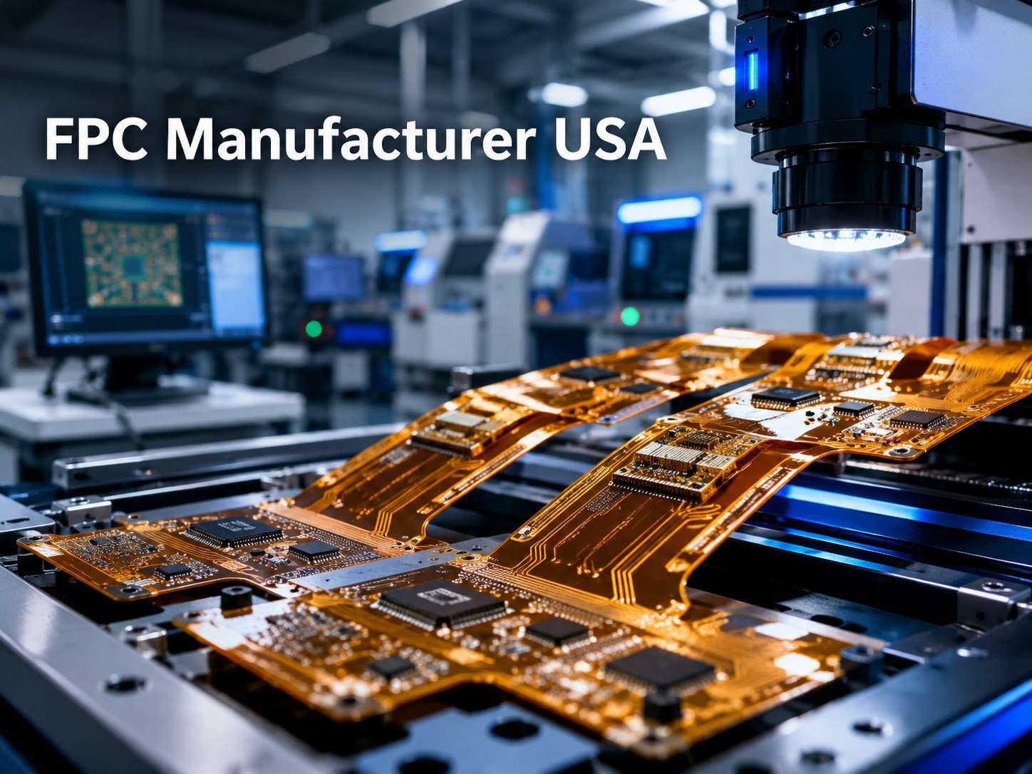
For buyers searching FPC manufacturer USA, the useful comparison is not simply who can make flexible circuits, but which supplier fits the actual construction: static or dynamic flex, multilayer routing, controlled impedance, stiffeners, rigid-flex transitions, direct SMT assembly, and production volume.

EBest Circuit supports U.S. FPC projects through flexible PCB and rigid-flex fabrication, component sourcing, PCBA, testing, and box build from our manufacturing operations in China and Vietnam. For projects that do not require U.S.-only production, we can support prototype, NPI, and repeat production within one manufacturing workflow.

FPC manufacturer USA

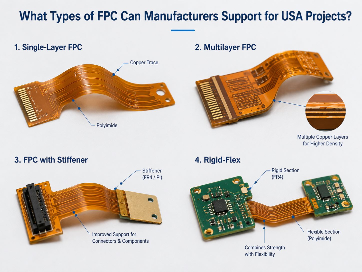
What Types of FPC Can Manufacturers Support for USA Projects?

FPC suppliers serve very different product categories, so layer count alone is not enough to judge capability.

FPC manufacturer USA
FPC Type Typical Requirement
Single-layer FPC Simple interconnects, sensors
Double-layer FPC More routing, plated vias
Multilayer FPC Higher density, impedance control
Static flex Installation bending
Dynamic flex Repeated motion
FPC with stiffener Connector or SMT support
Rigid-flex Rigid component zones + flex interconnect

The main manufacturing differences come from material construction, total flex thickness, copper type, coverlay, stiffener design, and bend duty.

For repeated movement, rolled-annealed copper and a thinner flex construction are often preferred. For high-density or high-speed designs, multilayer registration, dielectric control, and impedance become more important. Connector tails may instead depend mainly on contact thickness, stiffener tolerance, and dimensional accuracy.

When comparing suppliers, first confirm that their experience matches the exact FPC type you are buying.

How Should USA Buyers Choose an FPC Manufacturer for Their Project?

The right supplier changes with the application.

Static FPC

For a 1–2 layer flex that bends only during installation, prioritize:

  • Finished dimensions
  • Coverlay registration
  • Stiffener thickness
  • Contact-finger geometry
  • Delivery consistency

Dynamic FPC

For robotics, moving sensors, hinges, or other repeated-motion applications, focus more on:

  • Copper type
  • Flex thickness
  • Bend radius
  • Trace layout through the bend
  • Via and stiffener location
  • Flex-cycle requirements

High-density or controlled-impedance FPC

For camera, medical, sensing, and compact computing designs, the supplier may also need:

  • Fine trace/space
  • Multilayer flex capability
  • Tight thickness control
  • Controlled impedance
  • Stable low-loss material options

Assembled FPC

If components are mounted directly on the flex, also look at carrier fixtures, local stiffening, connector assembly, reflow control, AOI, X-ray, and functional test capability.

Choose the manufacturer around the FPC construction and operating condition, not around the longest factory capability list.

Top 15 FPC Manufacturers in the USA

The U.S. has established FPC suppliers serving medical, aerospace, defense, industrial, semiconductor, and commercial electronics. The table below is a sourcing shortlist rather than a strict ranking.

Manufacturer Main Strength Typical Fit
TTM Technologies Complex flex / rigid-flex High-reliability programs
Summit Interconnect Flex, rigid-flex, NPI Complex prototypes
All Flex Solutions Flex + assembly Medical, industrial
Minco Flex circuits + integration Medical, industrial
Tech Etch Flex, rigid-flex, SMT Aerospace, medical
Cirexx Flex + in-house PCBA Quick-turn complex builds
Pioneer Circuits Advanced rigid-flex Aerospace, defense
Lenthor / Fralock Flex, rigid-flex, assembly High-reliability NPI
FlexPCB.com Quick-turn flex Prototype to production
Circuits Unlimited Flex + assembly Prototype through volume
Sierra Circuits Engineering + DFM Complex prototypes
Rigiflex Technology Flex / rigid-flex Industrial, medical
GC Aero Flexible Circuits U.S. flex production Aerospace, military
Rigid-Flex International Multilayer flex Dense designs
Tramonto Circuits Custom PCB / flex General U.S. projects

For U.S.-only programs, verify the manufacturing location for the specific product, not only the supplier’s headquarters.

For projects without domestic-source restrictions, compare U.S. and overseas suppliers on engineering support, material availability, assembly integration, production capacity, lead time, and total cost.

A startup buying a two-layer sensor FPC may not need the same supplier as an aerospace rigid-flex program. Likewise, a customer that needs FPC plus SMT may benefit more from an integrated PCB/PCBA manufacturer than from a bare-board specialist.

What FPC Bend and Design Requirements Matter for USA Projects?

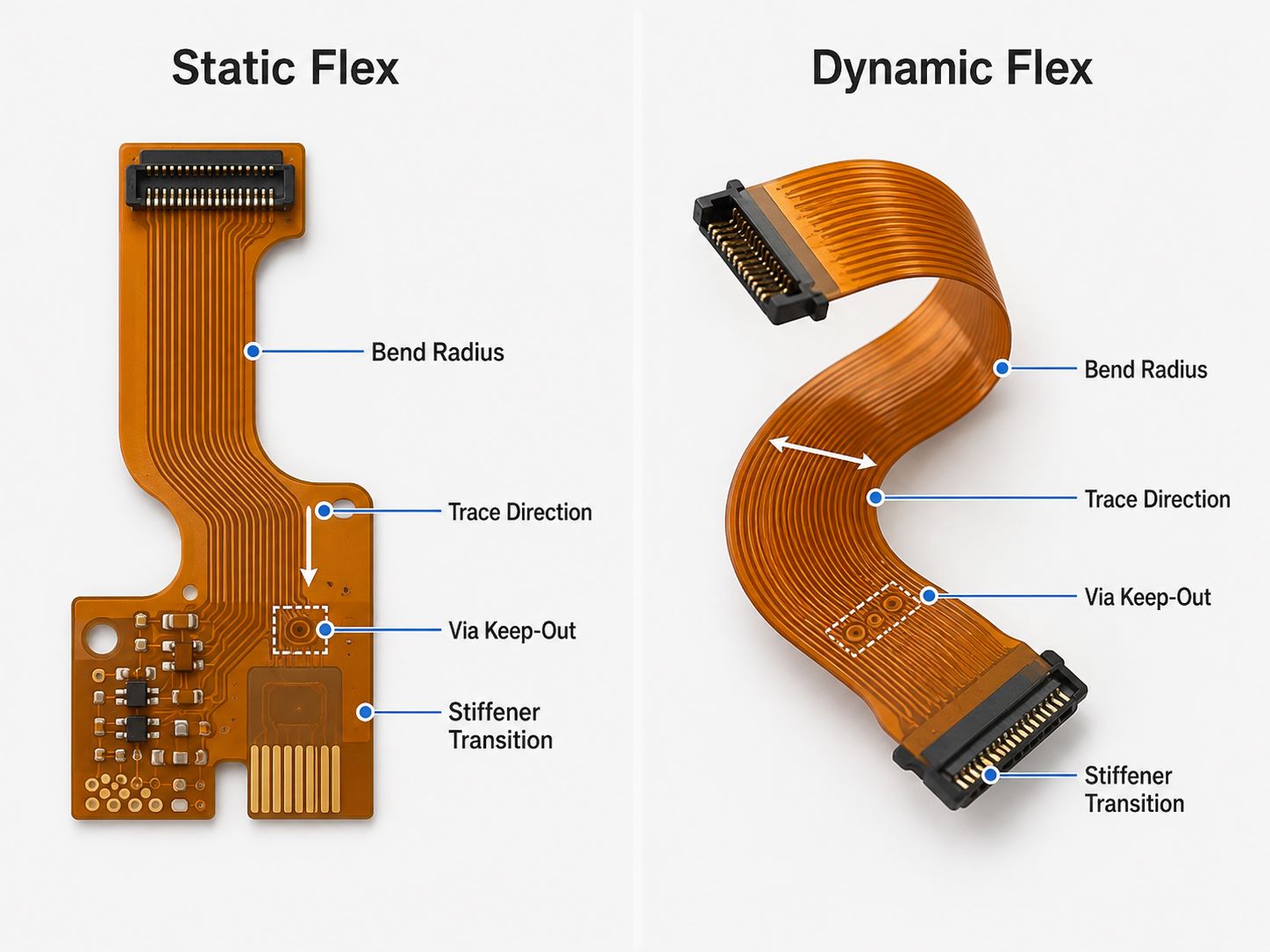
The main distinction is whether the flex is static or dynamic.

FPC manufacturer USA

A static circuit may only bend during installation. A dynamic flex repeatedly moves during use, so strain in the copper becomes a much larger design factor.

For bend regions, key items include:

  • Total flex thickness
  • Bend radius
  • Copper type
  • Trace direction
  • Copper distribution
  • Via distance from the bend
  • Coverlay termination
  • Stiffener transition

Avoid placing vias, plated holes, or abrupt rigid transitions inside high-strain bend areas where possible.

Multilayer FPC also needs more mechanical margin than a thin single- or double-layer flex because the thicker stack increases strain during bending.

Stiffener transitions deserve similar attention. FR-4 and PI stiffeners are useful around ZIF contacts, connectors, or SMT areas, but the end of the stiffener can become a local stress point if the mechanical transition is too abrupt.

For dynamic products, bend geometry should be defined from the actual mechanical envelope rather than finalized after the PCB stack-up is already fixed.

What FPC Assembly and Testing Matter for USA Electronics Projects?

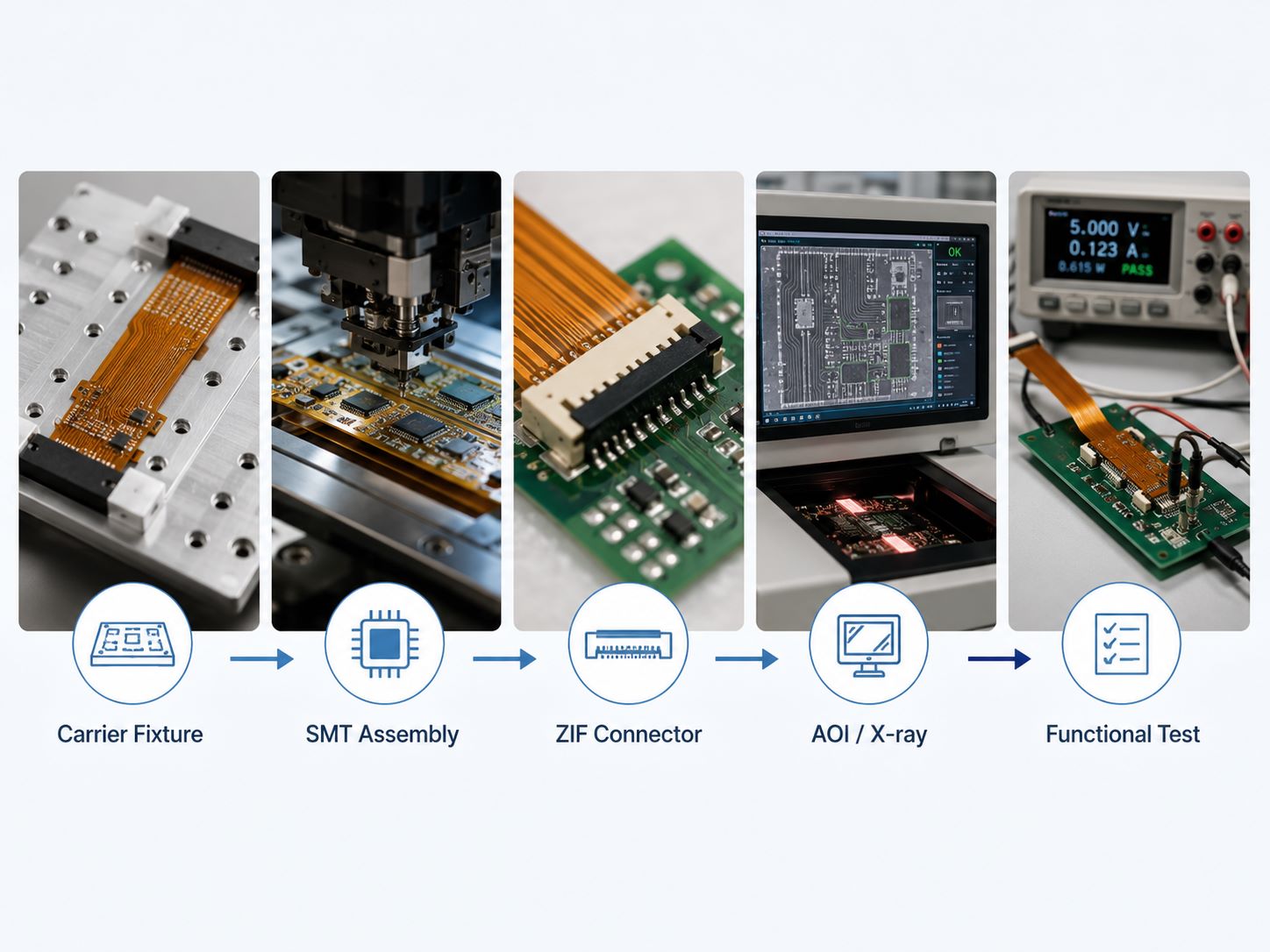
The key assembly issue is keeping the flex stable during printing, placement, and reflow.

FPC manufacturer USA

Thin FPC may curl or shift on standard SMT equipment, so carrier fixtures are often used to support the circuit through production.

Typical assembly considerations include:

  • Carrier or pallet design
  • Local stiffeners under component areas
  • Fine-pitch placement
  • ZIF and board-to-board connectors
  • Double-sided SMT
  • Reflow profile
  • Component sourcing

Testing should match the product rather than follow a fixed checklist.

Stage Typical Check
Bare FPC Electrical test
Critical dimensions Dimensional inspection
Controlled impedance Impedance test
SMT paste SPI
Visible joints AOI
Hidden joints X-ray
Finished assembly Functional test
Dynamic flex Bend-cycle test if specified

For assembled FPC, using the same supplier for fabrication and PCBA can simplify issues involving stiffener thickness, panelization, fixture support, pad design, and soldering.

How Can DFM Reduce FPC Prototype Risk for USA Projects?

The most useful FPC DFM work is usually around mechanical and assembly conflicts that are easy to miss in the layout.

Common examples include:

  • Vias too close to the bend zone
  • FPC + stiffener thickness that does not match the ZIF connector
  • SMT regions without enough support
  • Multilayer flex that is too thick for the required bend radius
  • Coverlay openings too close to bend transitions
  • Panel layouts that do not hold thin flex flat during assembly

At EBest Circuit, we review bend areas, via locations, coverlay, stiffeners, connector geometry, finished thickness, panelization, and assembly support together before production.

This is particularly useful when the project includes both bare FPC manufacturing and SMT assembly, because a change made for fabrication can also affect fixture design or connector fit.

The goal is not only to make the FPC, but to make it bend, assemble, and repeat reliably.

FPC Manufacturing Case Study for USA Buyers: From Prototype DFM to Stable Production

One EBest Circuit project involved a thin four-layer controlled-impedance FPC. The available project record does not identify the customer’s country, so it is presented here as a manufacturing reference for USA buyers rather than as a U.S.-customer claim.

Project Specifications

Item Requirement
Structure 4-layer FPC
Trace / space 75 / 75 μm
Minimum drilling 0.20 mm
Finished thickness 0.20 ± 0.03 mm
Impedance 100 ± 10 Ω / 50 ± 5 Ω
Surface finish ENIG
Material Low-Dk / low-Df flex material

Challenge

The combination of 75/75 μm routing, 0.20 mm finished thickness, and controlled impedance left little room to change the stack-up independently during production.

EBest Circuit Solution

The flex material, layer structure, impedance geometry, drilling, and finished thickness were confirmed together before release so the same construction could be retained for repeat builds.

Result

The project moved forward with a defined FPC stack-up and controlled critical parameters rather than relying on production-stage adjustments.

For a precision FPC, stable repeat production starts with locking the construction during the prototype stage.

Why USA Companies Work With EBest Circuit for FPC Manufacturing

EBest Circuit is not a U.S. domestic manufacturer; our production is based in China and Vietnam. For USA projects open to global sourcing, the advantage is not one isolated FPC process, but the ability to keep engineering, fabrication, sourcing, assembly, and repeat production under one manufacturing partner.

  • Broader FPC coverage: We support single-, double-, and multilayer FPC, rigid-flex, controlled impedance, PI/FR-4 stiffeners, and fine-pitch assembly.
  • PCB and PCBA stay connected: Stiffener thickness, connector areas, panelization, SMT fixtures, and component placement can be handled within one engineering workflow instead of being split between separate suppliers.
  • Flexible sourcing models: Customers can choose turnkey, partial-turnkey, or consigned-component assembly depending on how they want to control strategic parts.
  • Prototype to production continuity: Material, stack-up, stiffener construction, assembly method, and test requirements can remain consistent as volume increases.
  • Engineering and quality support: DFM, impedance review, AOI, X-ray, functional testing, traceability, and quality systems such as ISO 9001, ISO 13485, IATF 16949, and AS9100D support projects with different reliability requirements.

For an experienced USA sourcing team, the practical value is fewer supplier interfaces, clearer technical ownership, and a more direct path from FPC prototype to assembled production when U.S.-only manufacturing is not required.

FAQs About FPC Manufacturer USA

1. What is the typical lead time for FPC manufacturing for USA customers?

Simple prototype FPCs may be completed within several working days. Multilayer flex, rigid-flex, special materials, controlled impedance, unusual stiffeners, or assembled FPC usually require longer. Material availability and quantity also affect the final schedule.

2. Can an FPC manufacturer support both flex PCB and rigid-flex PCB?

Some can, but rigid-flex requires additional control of rigid-to-flex transitions, multilayer lamination, registration, and mechanical construction. Confirm specific rigid-flex experience rather than assuming standard FPC capability covers both.

3. What is the minimum order quantity for a custom FPC?

There is no standard MOQ. Prototype suppliers may accept a few pieces, while production pricing depends on panel utilization, tooling, material usage, assembly setup, and order volume.

4. Can FPC manufacturers provide UL, RoHS, and material traceability documents?

Many qualified manufacturers can provide applicable compliance and material documentation. Requirements for UL recognition, specific material brands, IPC acceptance criteria, RoHS, REACH, or lot traceability should be stated before production.

5. Can a USA company use an overseas FPC manufacturer?

Yes, if the project does not require U.S.-only manufacturing. In that case, compare suppliers on engineering support, material control, process capability, production repeatability, communication, logistics, and total cost.

Ready to Discuss Your FPC manufacturer USA Project? If you are developing a flexible PCB, rigid-flex assembly, wearable device, medical electronics, sensor module, compact industrial product, or other flex-based hardware, send your Gerber or ODB++, stack-up, stiffener drawing, BOM, assembly files, quantity, and test requirements to sales@bestpcbs.com. Our engineering team can review the FPC before quotation and identify fabrication, bend, assembly, sourcing, or testing issues that may affect prototype or volume production.

If you would like to evaluate our manufacturing capabilities in person, you are welcome to visit our factory. We can arrange a factory tour for your engineering or sourcing team to review PCB/FPC fabrication, SMT assembly, inspection, testing, and quality-control processes. To send project files or arrange a visit, contact sales@bestpcbs.com.

You may also like

Flexible PCB Board: Materials, Types, Design Rules and Cost Factors

July 20th, 2026

A flexible pcb board is a printed circuit built on a bendable dielectric film, usually polyimide, instead of a rigid laminate. It can replace wires and connectors, route signals through tight three-dimensional spaces, and move with a product. Reliable results depend on treating the bend requirement, material stack, copper construction, thickness and component locations as one system.

Flexible PCB board bending in a smooth curve on an engineering workbench

The first design question is not simply whether the circuit can bend. The team must define whether it bends only during installation or moves throughout the product’s service life. That distinction changes the stackup, copper choice, trace routing, bend radius, reinforcement and qualification plan.

What Is a Flexible PCB Board and When Should You Use One?

A flexible printed circuit board (PCB), also called an FPC or flex circuit, carries etched conductors on a thin flexible substrate. Use one when a conventional rigid board plus cable assembly creates too much volume, weight, assembly work or interconnection risk.

A flex circuit is especially useful when it must:

  • fit around a housing, hinge, camera module, battery or other mechanical feature;
  • replace point-to-point wiring with a repeatable conductor pattern;
  • connect rigid sections without a separate cable and connector pair;
  • reduce package thickness or weight; or
  • survive controlled motion when the stackup is designed for dynamic flexing.

Pure flex is not automatically the best choice for every compact assembly. If components need a mechanically stable mounting area and the flexible interconnect must be permanently integrated with that area, a rigid-flex PCB may reduce connectors and assembly steps. If the circuit only needs to bridge two existing boards, a cable or flex jumper may be simpler to service.

Which Flexible PCB Board Materials Shape Performance?

The flexible pcb board material system controls electrical insulation, bend behavior, temperature exposure, dimensional stability and manufacturing yield. A useful material review looks beyond the base film and includes the conductor, bonding system, coverlay, stiffeners, shielding and exposed-pad finish.

Exploded flexible PCB material stack with polyimide, copper, coverlay and connector stiffener
Material element What it does Selection question
Polyimide film Provides the flexible dielectric foundation and electrical insulation. What temperature, dimensional stability and bend-life conditions must the circuit withstand?
Rolled-annealed or electrodeposited copper Forms the conductors; copper grain structure and thickness influence flex fatigue and etching behavior. Is the application static, installation-flex or dynamic-flex, and what current and fine-line needs apply?
Adhesive or adhesiveless construction Bonds copper and dielectric layers or removes a separate adhesive layer from the core construction. Is lower thickness, tighter bending or repeated movement more important than the economics of a conventional construction?
Coverlay Protects conductors while leaving pads and contact areas exposed. Can the coverlay opening and adhesive flow be controlled around fine-pitch pads and bend transitions?
Stiffener Reinforces a connector, component or contact area without making the entire circuit rigid. Where must insertion force, component support or finished thickness be controlled?
Shielding layer Supports EMI control and reference continuity but adds thickness and can reduce flexibility. Does the electrical need justify the mechanical and cost trade-off?

Material names alone do not define performance. The copper weight, adhesive thickness, coverlay construction, plated features and local reinforcement all change the finished stack. For a deeper material review, see the BestPCBs guide to flexible PCB materials.

Which Flexible PCB Types Fit Different Layer and Bend Needs?

The main flexible pcb types are single-sided, double-sided and multilayer flex circuits, plus rigid-flex constructions that combine rigid and flexible sections. Choose the simplest structure that meets routing, shielding, current, connector and mechanical needs because every added layer increases thickness and makes the bend region harder to manage.

Type Best fit Main design watchpoint
Single-sided flex Simple jumpers, sensors, membrane interfaces and low-density interconnects. Limited routing and no plated connection between conductor sides.
Double-sided flex More routing density, plated-through connections and circuits needing conductors on both sides. Added copper and plating make the stack less compliant than a single-sided circuit.
Multilayer flex Dense signal routing, shielding, controlled references or complex interconnection. Layer count, bonded areas and via placement must be coordinated with the intended bend zones.
Rigid-flex PCB Assemblies that need component-bearing rigid areas connected by integrated flexible sections. The rigid-to-flex transition, layer construction and fabrication sequence require early supplier review.

Do not select a layer count from routing density alone. First identify the active bend area, then check whether reference planes, shielding, plated holes or bonded multilayer sections can stay outside it. A thinner, simpler flex tail connected to a rigid component area may be more reliable than forcing every electrical feature through a moving zone.

Flexible PCB Design Rules for Reliable Bending

Reliable flexible pcb design keeps mechanical strain low and avoids local stress concentrations. The bend region should be treated as a controlled mechanical feature, not as leftover routing space after the electrical layout is complete.

Static folded flex circuit and dynamic flex circuit moving through a smooth hinge bend
  • Define the motion: record whether the bend occurs once during assembly, occasionally during service or continuously through many cycles.
  • Route traces through the bend: use smooth, consistent paths and avoid abrupt width changes, sharp corners and unnecessary jogs in high-strain areas.
  • Keep discontinuities away: move vias, plated holes, component pads and stiffener edges out of the active bend wherever the design permits.
  • Stagger features: avoid creating a straight line of vias or pad edges that concentrates strain across the circuit width.
  • Manage copper direction: align conductor paths with the intended bending action and review plane or hatch patterns for both electrical and mechanical behavior.
  • Use gradual transitions: add suitable fillets, teardrops or other strain-relief geometry where conductors enter pads, subject to fabricator DFM rules.
  • Control the installed shape: prevent folds, pinching, torsion and contact with sharp housing edges.

Static and dynamic flex should not share an unexamined rule set. A circuit bent once and retained in a housing can often use a different stack and routing approach from a circuit moving in a hinge. Review bend direction, bend angle, available envelope, motion cycles and environmental conditions with the manufacturer before freezing the mechanical design.

How Do Flexible PCB Thickness, Bend Radius and Stiffeners Work Together?

Flexible pcb thickness and bend radius are linked: a thicker, more heavily bonded stack generally develops more strain for the same bend geometry. Stiffeners solve local support problems, but their edges also create transitions that must be kept away from active bending.

There is no single bend-radius multiplier that is safe for every flex circuit. The required radius depends on:

  • single-sided, double-sided or multilayer construction;
  • finished thickness and local thickness changes;
  • copper type, copper thickness and plating;
  • adhesive-based or adhesiveless materials;
  • static installation versus repeated dynamic movement;
  • trace orientation and density inside the bend;
  • coverlay, shielding and reinforcement; and
  • temperature, assembly constraints and expected service life.

Use IPC-2223 as a design reference, then obtain a stack-specific DFM review instead of treating one online ratio as a universal guarantee. The BestPCBs overview of IPC-2223 and flex PCB bend radius explains why construction and use conditions must accompany any bend recommendation.

What Are the Advantages and Disadvantages of a Flexible PCB?

A flex circuit can reduce interconnect volume, weight and assembly complexity, but it demands closer coordination between electrical, mechanical and manufacturing decisions. Its value should be judged at the assembly level, not by bare-board price alone.

Potential advantage Corresponding limitation
Routes through compact three-dimensional spaces. The installed bend and housing clearances must be controlled.
Can replace wires and connector interfaces. Design changes may require a new artwork, tooling or mechanical review.
Supports low-profile, lightweight assemblies. Thin circuits need suitable handling, fixtures and support during assembly.
Provides repeatable conductor routing. Poor bend-zone layout can create concentrated copper fatigue.
Can move with hinges or mechanisms when designed for dynamic use. Dynamic life depends on the complete material stack, geometry and motion profile.
May simplify final assembly and reduce interconnection count. Bare flex fabrication can cost more than a comparable simple rigid board.

A design that saves two connectors, a cable and manual routing time may reduce total installed cost even when the flex circuit itself has a higher unit price. Conversely, a simple stationary product with generous space may gain little from flexible construction.

What Drives Flexible PCB Board Price and Supplier Selection?

Flexible pcb board price is driven by the stackup, panel utilization, feature density, reinforcement, surface finish, testing and production volume. A useful quote therefore needs more than Gerber files and a layer count.

Common cost and manufacturability drivers include:

  • board outline, nesting efficiency and array or panel requirements;
  • material family, adhesiveless construction, copper type and copper thickness;
  • layer count, finished thickness and selective bonding requirements;
  • minimum trace, spacing, annular ring and hole features;
  • coverlay openings, fine-pitch pads and adhesive-flow control;
  • stiffeners, shielding films, pressure-sensitive adhesive and local reinforcement;
  • surface finish, impedance requirements and electrical testing;
  • prototype versus production quantity and repeat-order expectations; and
  • assembly fixtures, component loading and final functional tests when PCBA is included.
Engineer inspecting flexible PCB bend zones, traces and reinforced connector area

When comparing flexible pcb board manufacturers, ask each supplier to review the same controlled data package. Include fabrication files, drawing, stackup, material requirements, finished thickness, stiffener details, bend location, bend direction, minimum installed radius, expected motion cycles, surface finish, test requirements, quantities and assembly scope. This makes quotations more comparable and exposes DFM assumptions before they become production changes.

For a manufacturing-focused evaluation path, review BestPCBs’ flex PCB manufacturer page, then request written confirmation for the exact stackup and mechanical use case rather than relying on a generic capability statement.

Flexible PCB Board RFQ Checklist

A complete RFQ should define the mechanical life of the circuit as clearly as its electrical construction. The following inputs reduce avoidable assumptions during DFM and quotation.
  1. Gerber or ODB++ fabrication data, drill files, netlist and a controlled drawing.
  2. Layer stack, copper requirements, base film, coverlay and any adhesive restrictions.
  3. Finished thickness, thickness tolerance and local stiffener thickness.
  4. Bend-zone drawing with bend direction, angle, available radius and installed envelope.
  5. Static, installation-flex or dynamic-flex classification, including expected cycles for moving designs.
  6. Connector, contact-finger, component and assembly requirements.
  7. Surface finish, impedance, shielding, pressure-sensitive adhesive and marking requirements.
  8. Electrical test, dimensional inspection, reliability or functional-test requirements.
  9. Prototype quantity, production volumes, panel preferences and delivery destination.

Mark critical dimensions and bend restrictions on the drawing rather than leaving them in an email thread. If the supplier proposes a material or stack change, request an updated stackup and confirm its effect on thickness, impedance, bending and assembly interfaces before approval.

Frequently Asked Questions

Is a flex board the same as an FPC?

In most PCB manufacturing contexts, flex board, flexible circuit and FPC refer to the same product family: patterned conductors supported by a flexible dielectric. Individual suppliers may use the terms differently for product categories, so the fabrication drawing and stackup should define the construction instead of relying on the label alone.

Can a flexible PCB be bent repeatedly?

Yes, but only when it is designed for dynamic flexing. Repeated motion requires a compatible material stack, suitable copper, controlled thickness, smooth trace routing, an adequate bend radius and a defined motion path. A circuit designed only for installation flex should not be assumed to survive continuous hinge movement.

How many layers can a flexible PCB have?

Flexible circuits can be single-sided, double-sided or multilayer. The practical layer count depends on the fabricator, material set, routing density and whether the area must bend. More layers increase thickness and strain, so designers often keep active bend zones simpler than component or termination areas.

Why can a flexible PCB cost more than a rigid PCB?

Flex fabrication uses specialized films, coverlay processing, handling, reinforcement and inspection. Complex outlines and low panel utilization can also affect price. The relevant comparison is total assembly cost: a flex circuit may remove cables, connectors and manual wiring even when its bare-board price is higher.

Can components be mounted directly on a flexible PCB?

Yes. Component areas normally need suitable support, land patterns, assembly fixtures and strain control. Stiffeners are often used beneath connectors or component regions, while active bending is kept away from solder joints and abrupt stiffener edges.

Which surface finishes can be used on flexible PCB pads?

Several common PCB finishes can be applied, but the correct choice depends on pad function, soldering, contact wear, storage, assembly process and supplier capability. Connector fingers and solderable component pads may have different requirements, so define each finish area on the fabrication drawing.

Can controlled impedance be designed on a flex circuit?

Yes. Impedance control requires defined dielectric thickness, copper geometry, reference structure and material properties. Bending and stack transitions can affect geometry, so controlled-impedance regions and moving zones should be reviewed together with the fabricator.

Should vias be placed in a bend area?

Vias are stress discontinuities and should generally be kept outside an active bend when the layout allows. If packaging makes that impossible, the via construction, reinforcement, bend direction and use condition need an explicit DFM and reliability review.

Can a damaged flexible PCB be repaired?

Some pad, trace or component-area defects may be repairable under a controlled procedure, but damage in a repeatedly flexing region is difficult to restore reliably. Repair feasibility depends on access, conductor geometry, insulation restoration and the product’s reliability requirements.

What files are needed for a flexible PCB quote?

Provide fabrication data, drill files, a controlled drawing, stackup, material and thickness requirements, stiffener details, bend-zone geometry, motion classification, finish, testing needs and quantities. For assembly, also include the BOM, centroid data, assembly drawings and any programming or functional-test instructions.

Plan the Stackup Around the Bend Requirement

A dependable flex circuit starts with a defined mechanical use case. Establish the bend zone and motion profile first, then select materials, copper, layer count, thickness, stiffeners and routing that support that requirement. Complete drawings and early DFM review are more valuable than applying a generic bend rule after layout.

If you need a flex PCB fabrication or assembly review, send the BestPCBs engineering team your files, stackup, quantities, bend radius and motion-cycle requirements at sales@bestpcbs.com. The team can review manufacturability and prepare a project-specific quotation.
You may also like

Polyester Printed Circuitry Guide | Flexible PCB Materials

July 15th, 2026

Polyester printed circuitry usually refers to conductive circuits printed on polyester film, often PET, using silver ink or other conductive materials. It is commonly used in membrane switches, low-current flexible circuits, wearable electronics, printed sensors, control panels, and lightweight electronic interfaces.

For engineers, the important question is not only ā€œWhat is polyester printed circuitry?ā€ but also ā€œIs polyester the right material for this product, or should the project use polyimide circuit board, copper flex, rigid-flex PCB, or another flexible PCB structure?ā€ EBest Circuit (Best Technology) supports flexible PCB, rigid-flex PCB, PCB fabrication, component sourcing, PCBA assembly, DFM review, and manufacturing feasibility checks. If you are comparing polyester printed circuitry with FPC manufacturing, send your drawings, Gerber data, stackup notes, material requirements, connector area, stiffener needs, and application environment to sales@bestpcbs.com for engineering review.

polyester printed circuitry

What Is Polyester Printed Circuitry?

Polyester printed circuitry is a type of flexible circuit made by printing conductive material onto polyester film. The base material is usually PET polyester, and the conductive path is often made with printed silver ink, carbon ink, or other conductive materials.

It is different from traditional copper flexible PCB manufacturing. In many polyester printed circuits, the circuit pattern is printed rather than etched from copper foil.

Common features include:

FeaturePolyester Printed Circuitry
Base materialPET polyester film
Conductive materialSilver ink, carbon ink, or conductive ink
Manufacturing methodPrinting process
Typical circuit typeLow-current, flexible, lightweight circuit
Common useMembrane switches, sensors, wearables, control panels
StrengthThin, flexible, cost-effective for selected applications
LimitationNot ideal for every high-reliability or high-current application

Polyester printed circuitry is useful when the circuit needs to be thin, flexible, and cost-efficient, especially for switch circuits or simple conductive paths. However, if the product needs soldered components, tighter copper features, higher temperature resistance, plated through holes, ENIG pads, or stronger long-term reliability, polyimide FPC may be a better choice.

polyester printed circuitry

Polyester PCB Boards and Flexible Printed Circuits

The term ā€œpolyester PCB boardsā€ can be confusing. In many cases, it refers to a flexible circuit built on polyester film, not a traditional rigid PCB board.

Flexible printed circuits can use different materials and processes:

Circuit TypeTypical MaterialCommon Process
Polyester printed circuitryPET polyesterPrinted conductive ink
Polyimide FPCPI filmCopper etching and plating
Rigid-flex PCBFR4 + PIMultilayer PCB fabrication
Membrane switch circuitPolyester or polyimidePrinted or etched circuit
Printed electronicsPET, paper, textile, or filmConductive ink printing

For simple switch panels, polyester may be suitable. For fine-pitch connectors, soldered components, higher reliability, and plated copper structures, polyimide FPC is often more practical.

This is why material selection should be reviewed before production. A project may look like ā€œpolyester printed circuitryā€ at the concept stage, but the final manufacturing path may need polyimide FPC or rigid-flex PCB depending on reliability, connector, temperature, and assembly requirements.

polyester printed circuitry

Polyester Printed Circuitry Materials and Structure

A typical polyester printed circuit may include several layers.

LayerPurpose
Polyester filmFlexible base substrate
Conductive inkForms the circuit pattern
Insulating layerSeparates conductive paths
Adhesive layerBonds layers together
Overlay or graphic layerProtects or labels the surface
Connector tailConnects to another board or device
Stiffener if neededAdds support at connector area

The exact structure depends on the product. A membrane switch circuit may need a graphic overlay and spacer layers. A printed sensor may need exposed conductive areas. A wearable circuit may need flexibility, low thickness, and stable connection to a module.

Key engineering checks include:

  • Current requirement
  • Flexing requirement
  • Contact resistance
  • Connector method
  • Operating temperature
  • Humidity exposure
  • Surface protection
  • Adhesive selection
  • Assembly method
  • Expected product lifetime

Polyester film is useful for many low-current applications, but it does not replace every flexible PCB material. If a project has soldering, plating, dense copper traces, or high-temperature assembly, polyimide FPC should be considered.

Printed Silver on Polyester vs Copper on Kapton

One of the most important comparisons is printed silver on polyester vs copper on Kapton.

Kapton is a common trade name associated with polyimide film. In PCB manufacturing, copper on polyimide is widely used for flexible printed circuits.

ItemPrinted Silver on PolyesterCopper on Kapton / Polyimide
Base materialPET polyesterPolyimide
ConductorPrinted silver inkCopper foil
ProcessPrintingEtching, plating, lamination
Current capacityUsually lowerUsually stronger
Temperature resistanceLower than PIBetter thermal resistance
Fine featuresProcess-dependentBetter for PCB-style routing
SolderingLimitedMore suitable
Typical useMembrane switches, sensors, low-current circuitsFPC, rigid-flex, assembled flex circuits

Printed silver on polyester can be cost-effective for selected applications. Copper on polyimide is usually better when the circuit needs stronger conductivity, plated pads, component assembly, or more demanding reliability.

The right choice depends on the application. A low-current user interface may work well with polyester printed circuitry. A compact electronic module with connectors, ENIG pads, or SMT assembly usually needs FPC manufacturing.

polyester printed circuitry

Polyester vs Polyimide Flexible PCB Materials

Polyester and polyimide are both used in flexible electronics, but they are not the same.

MaterialStrengthLimitation
Polyester / PETCost-effective, flexible, good for printed circuitsLower heat resistance
Polyimide / PIHigher heat resistance, stronger for FPC manufacturingUsually higher cost
FR4 stiffenerAdds mechanical supportNot flexible
Adhesiveless PIGood for thin, reliable FPCNeeds careful manufacturing control

Polyester can be useful for membrane switches, simple printed circuits, low-current sensors, and flexible interfaces. Polyimide is usually preferred for flexible PCB manufacturing when the project needs:

  • Copper traces
  • Plated holes
  • ENIG finish
  • Soldered components
  • Connector fingers
  • Fine pitch routing
  • Better heat resistance
  • Repeated bending reliability
  • FR4 or PI stiffener
  • PCBA assembly

This difference matters for sourcing. If a buyer searches for polyester printed circuitry but actually needs a copper FPC with ENIG and stiffeners, the project should be reviewed as an FPC manufacturing project, not only a printed electronics project.

polyester printed circuitry

Where Polyester Flexible Circuits Are Commonly Used

Polyester flexible circuits are often used where the circuit must be thin, lightweight, and flexible.

Common applications include:

  • Membrane switch panels
  • Keypads
  • Human-machine interfaces
  • Low-current control circuits
  • Printed sensors
  • Wearable electronics
  • Smart clothing prototypes
  • Disposable or semi-disposable electronics
  • Flexible LED interface circuits
  • Medical patches or sensor interfaces
  • Consumer device control panels

Polyester is especially useful when the circuit is not exposed to high temperature, high current, or demanding soldering conditions.

For industrial electronics, medical electronics, automotive electronics, or compact modules with connectors and soldered parts, polyimide FPC or rigid-flex PCB may be safer. The final choice should be based on electrical load, bending life, environment, assembly method, and reliability requirements.

polyester printed circuitry

Double-Sided Printed Electronics on Polyester Film

Double-sided printed electronics on polyester film can support more routing options than a single-sided printed circuit. It may use conductive vias, printed interconnects, or other connection methods depending on the manufacturing process.

A double-sided structure may be useful when:

  • Routing is limited on one side
  • Switch matrix layout needs crossing paths
  • Sensor electrodes need more complex connections
  • The product needs a compact flexible circuit
  • The connector tail requires a specific pin arrangement

However, double-sided printed electronics is not the same as a plated copper double-sided FPC. If the project needs plated through holes, fine copper traces, ENIG pads, or soldered components, a copper-based FPC may be more suitable.

Before choosing double-sided polyester printed circuitry, engineers should confirm:

  • Required resistance
  • Current level
  • Bend area
  • Connector method
  • Environmental exposure
  • Expected lifetime
  • Assembly process
  • Testing method

Polyester Printed Circuitry for Membrane Switches and Wearables

Polyester printed circuitry is widely used in membrane switches and wearable electronics because it can be thin, flexible, and lightweight.

Membrane switch circuits

In membrane switches, polyester printed circuitry can form key matrix circuits, contact pads, and flexible tails. The circuit is often combined with graphic overlays, spacer layers, adhesives, and connector tails.

Important checks include:

  • Contact resistance
  • Tail length
  • Connector pitch
  • Key life cycle
  • Adhesive compatibility
  • Surface protection
  • Moisture exposure
  • Bend area

Wearable electronics

For wearables, polyester printed circuitry may be used for low-current signal paths, sensors, or lightweight flexible connections. But if the product needs repeated bending, soldered components, washable structure, or higher reliability, polyimide FPC or textile electronics may need to be evaluated.

This is why material selection is not only about flexibility. It is about the real product environment.

Polyester Printed Circuitry Manufacturing Case Study

A European customer was developing a thin flexible circuit for a compact electronic interface. At the early sourcing stage, the customer compared polyester printed circuitry with copper-based flexible PCB manufacturing. After reviewing the connection area, thickness requirement, finish, and reinforcement needs, the project was handled as a 2-layer polyimide FPC rather than a printed silver polyester circuit.

Project snapshot

  • Customer: Europe
  • Application: Compact flexible interface circuit
  • Final process: 2L FPC
  • Panel format: Customer-specified panelization, single panel delivery
  • Panel size: 250mm x 70mm
  • Copper: 1/2oz copper + plating
  • Base material: 2mil adhesiveless PI
  • Bottom coverlay: 1mil coverlay
  • Top coverlay: Not required
  • FPC thickness: 0.15mm +/-0.03mm
  • Stiffener: 0.35mm FR4 stiffener
  • Final stiffened thickness: 0.5mm +/-0.05mm
  • Surface finish: ENIG, Au 1u”
  • Silkscreen: White silkscreen
  • Production control: Production files and stackup required customer confirmation before mass production

Why polyester printed circuitry was not the final choice

The customer needed a thin flexible circuit, but the project also required copper traces, plating, ENIG surface finish, controlled thickness, FR4 stiffener support, and production stackup confirmation. These requirements were closer to polyimide FPC manufacturing than printed silver on polyester.

EBest Circuit review focus

  • Checked the 2-layer FPC stackup before production
  • Reviewed 2mil adhesiveless PI and 1mil bottom coverlay structure
  • Confirmed the no-top-coverlay requirement
  • Checked 0.15mm +/-0.03mm FPC thickness control
  • Reviewed FR4 stiffener thickness and final 0.5mm +/-0.05mm area
  • Confirmed ENIG Au 1u” for contact reliability
  • Prepared production files and stackup for customer confirmation before production

Customer value

For the customer, the value was not only receiving a flexible circuit. The important value was choosing the right manufacturing path. Polyester printed circuitry may be suitable for printed switch or low-current applications, but this project needed a copper-based FPC structure with ENIG and FR4 stiffener. EBest Circuit helped clarify the material and manufacturing requirements before production, reducing the risk of using the wrong flexible circuit process.

How to Choose Between Polyester Printed Circuitry and Flexible PCB Manufacturing

Choosing between polyester printed circuitry and flexible PCB manufacturing depends on the real product requirements.

Polyester printed circuitry may be suitable when the project needs:

  • Low-current flexible circuit
  • Membrane switch
  • Printed sensor
  • Simple conductive path
  • Thin PET structure
  • Cost-sensitive flexible interface
  • No soldered components
  • Lower thermal demand

Polyimide FPC may be better when the project needs:

  • Copper traces
  • Plated holes
  • ENIG pads
  • Soldering
  • Connector fingers
  • FR4 stiffener
  • Higher heat resistance
  • More reliable flex performance
  • SMT assembly
  • PCBA integration

A practical supplier should ask for:

  • Drawing or Gerber data
  • Material requirement
  • Thickness requirement
  • Bend area
  • Connector area
  • Stiffener requirement
  • Surface finish
  • Current and voltage needs
  • Assembly notes
  • Application environment
  • Reliability requirement

EBest Circuit supports flexible PCB, rigid-flex PCB, PCB fabrication, component sourcing, PCBA assembly, and DFM review. If your project is not suitable for polyester printed circuitry, our engineering team can help review whether polyimide FPC, rigid-flex PCB, or another PCB structure is more practical for manufacturing.

FAQs about Polyester Printed Circuitry

1. What is polyester printed circuitry?

Polyester printed circuitry is a flexible circuit made by printing conductive material, often silver ink, onto polyester film. It is commonly used in membrane switches, low-current flexible circuits, printed sensors, and lightweight electronic interfaces.

2. Is polyester printed circuitry the same as flexible PCB?

Not exactly. Polyester printed circuitry often uses printed conductive ink on PET film. Flexible PCB usually refers to copper circuits on polyimide film, produced with PCB fabrication processes such as etching, plating, lamination, and surface finishing.

3. What is the difference between polyester and polyimide flexible circuits?

Polyester is cost-effective and useful for printed circuits and membrane switches. Polyimide has better heat resistance and is more suitable for copper FPC, ENIG pads, soldering, stiffeners, and more demanding electronic assemblies.

4. Can polyester printed circuitry use double-sided circuits?

Yes, double-sided printed electronics on polyester film are possible, but the structure is different from plated copper double-sided FPC. The right choice depends on routing, resistance, connector, and reliability requirements.

5. When should I choose polyimide FPC instead of polyester printed circuitry?

Choose polyimide FPC when the project needs copper traces, plated holes, ENIG, soldered components, FR4 stiffener, tight thickness control, or higher reliability than a printed polyester circuit can provide.

To conclude, if you are comparing polyester printed circuitry, polyester PCB boards, polyimide FPC, or rigid-flex PCB for a new project, send your drawings, Gerber data, material notes, thickness requirement, connector area, stiffener requirement, surface finish, and application environment to sales@bestpcbs.com. EBest Circuit’s engineering team can help review the manufacturing path before production and help you avoid choosing the wrong flexible circuit structure.

You may also like

Custom Etched Flex Circuits with Engineering Support

June 23rd, 2026

Custom etched flex circuits are widely used in compact electronic products where space, weight, and wiring reliability matter. In this article, we will explain what custom etched flex circuits are, how they are made, which materials are commonly used, and what buyers should consider before placing an order.

From medical devices and sensors to automotive electronics, wearable products, and industrial modules, flexible circuits help electronic products become smaller, lighter, and easier to assemble. At EBest Circuit, we support these projects with fast-turn prototypes, in-house manufacturing, and engineering review before production. Our team can evaluate material selection, bend areas, stiffener design, and manufacturability early in the process to help reduce development risks and speed up time to market. Have a custom flex circuit or flex PCB assembly project in mind? Pls feel free to contact our team at sales@bestpcbs.com for a quick engineering review and quotation.
Custom Etched Flex Circuits

What Are Custom Etched Flex Circuits?

Custom etched flex circuits are flexible printed circuits made by chemically etching copper traces on a flexible base material. The most common base material is polyimide, which offers good heat resistance, flexibility, and dimensional stability.

Unlike standard off-the-shelf cables, custom etched flex circuits are designed according to a specific product layout. The circuit shape, copper trace width, hole position, connector area, stiffener, surface finish, and coverlay opening can all be customized.

A typical flex circuit may include:

  • Flexible polyimide substrate
  • Copper conductive traces
  • Adhesive or adhesive-less copper structure
  • Coverlay insulation layer
  • Stiffeners for connector or component areas
  • Pads, vias, slots, and mounting holes
  • Surface finish such as ENIG, OSP, immersion silver, or tin

The main purpose of a custom flex circuit is to provide a reliable electrical connection in a small or movable space. It can replace bulky wires, reduce manual assembly, and support a cleaner internal product structure.

Custom Etched Flex Circuits

Why Are Flex Circuits Etched Instead of Wired?

Flex circuits are etched because etching allows precise copper patterns to be formed on a thin flexible substrate. This process creates a flat, repeatable, and compact circuit path.

Traditional wires are useful in many products, but they may occupy more space and require manual routing. When a product becomes smaller or more complex, wire harnesses can create assembly problems. Wires may cross each other, need extra fixing, or increase the risk of connection errors.

Etched flex circuits solve these issues by turning the circuit path into a controlled copper pattern. Each trace is placed exactly where it should be. This improves repeatability and makes assembly easier.

Etched flex circuits are especially useful when a product requires:

  • Thin and lightweight interconnection
  • Consistent circuit layout
  • Reduced manual wiring
  • Bending or folding inside the enclosure
  • Stable signal transmission
  • Cleaner internal product design
  • Easier mass production

For compact electronics, etched flex circuits often provide a more practical solution than individual wires.

What Materials Are Used in Custom Etched Flex Circuits?

Material selection has a strong effect on the flexibility, durability, cost, and electrical performance of a flex circuit. The most common materials include polyimide film, copper foil, coverlay, adhesive, stiffeners, and surface finishes.

  • Polyimide is the most widely used base material for flex circuits. It provides good thermal resistance and mechanical flexibility. It can handle bending and folding better than many rigid materials.
  • Copper foil forms the conductive traces. Rolled annealed copper is often used for dynamic bending applications because it has better flexibility. Electro-deposited copper is commonly used for applications where bending demand is lower.
  • Coverlay protects the copper traces and provides insulation. It is usually made from polyimide film with adhesive. Openings are created in the coverlay for solder pads, test points, and connector areas.
  • Stiffeners are added to areas that need mechanical support, such as connector zones or component mounting areas. Common stiffener materials include FR4, polyimide, and stainless steel.
  • Surface finish protects exposed copper pads and supports solderability. ENIG is common when good flatness, oxidation resistance, and fine-pitch compatibility are required.

Choosing the right material is not only about cost. It should match the product’s bending radius, working temperature, assembly process, and reliability requirements.

How Are Custom Etched Flex Circuits Manufactured?

The manufacturing process of custom etched flex circuits starts from design review and material preparation. Before production, engineers need to check the Gerber files, stack-up, trace width, spacing, bending area, stiffener position, and assembly requirements.
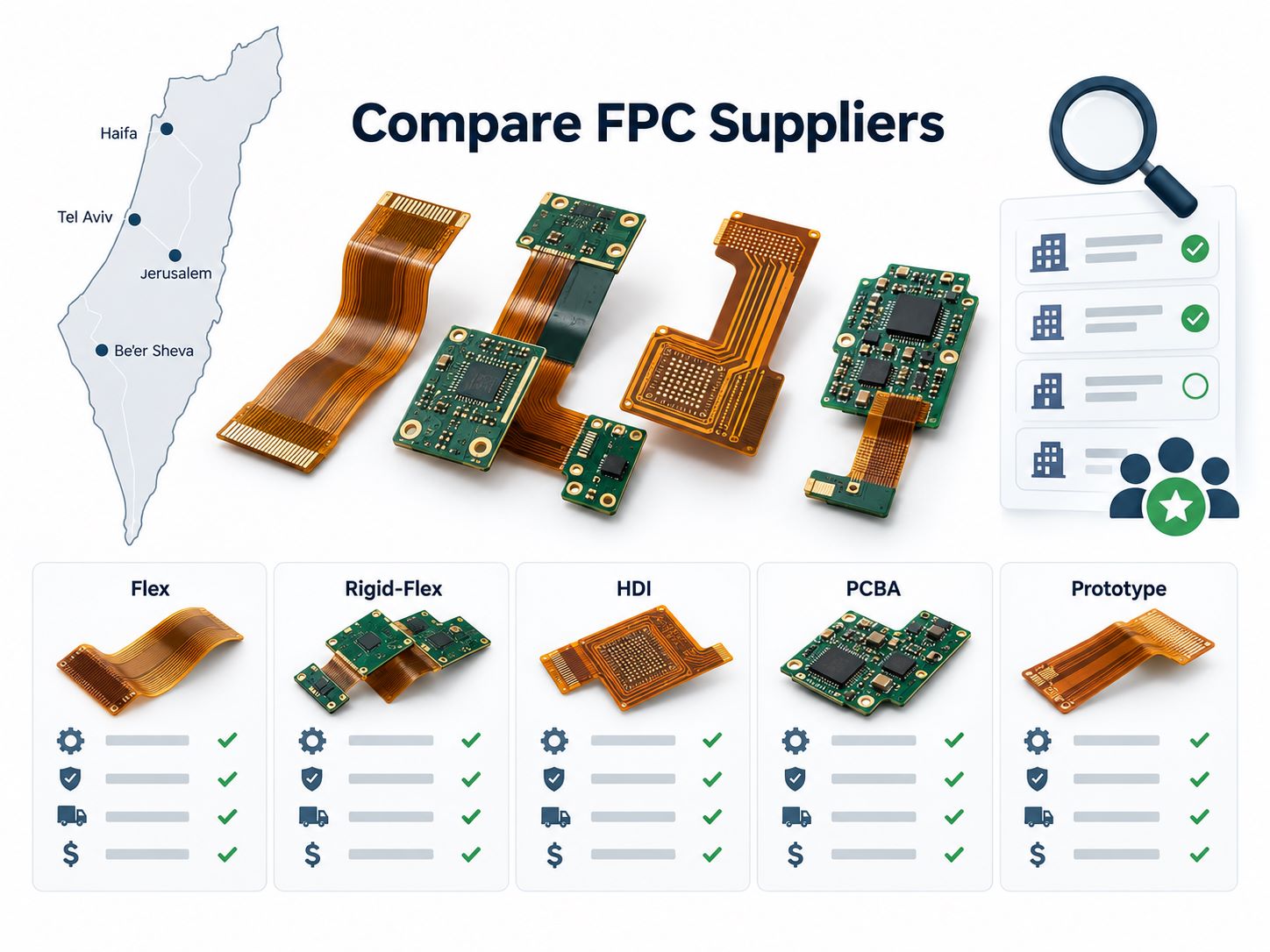
A standard process may include the following steps:

1. Engineering review

  • The manufacturer checks whether the design can be produced reliably. Important points include minimum trace width, spacing, hole size, pad design, bend area, and panel layout.

2. Material preparation

  • Polyimide copper-clad material is selected according to the project requirements. The copper thickness and substrate thickness must match the electrical and mechanical needs.

3. Imaging and exposure

  • The circuit pattern is transferred onto the copper surface through photoimaging.

4. Copper etching

  • Unwanted copper is removed by chemical etching. The remaining copper forms the designed circuit traces.

5. Drilling and punching

  • Holes, slots, and special shapes are created according to the design. For some projects, laser drilling may be used.

6. Coverlay lamination

  • A coverlay layer is laminated onto the circuit to protect the copper traces. Openings are left for solder pads and connection points.

7. Surface finish

  • The exposed pads receive surface finish treatment, such as ENIG, OSP, immersion silver, or tin.

8. Stiffener bonding

  • FR4, polyimide, or metal stiffeners are bonded to selected areas for support.

9. Electrical testing

  • The finished flex circuits are tested for open circuits, short circuits, and electrical continuity.

10. Final inspection and packaging

  • The products are inspected for appearance, dimension, pad quality, and cleanliness before shipment.

A well-controlled process helps custom etched flex circuits maintain stable performance from prototype to mass production.
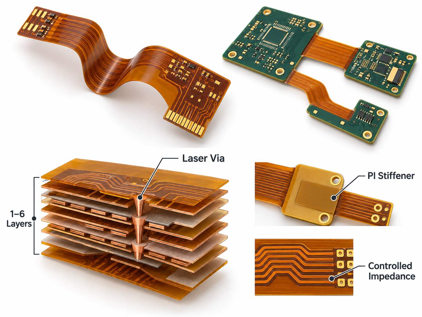
Custom Etched Flex Circuits

Where Are Custom Etched Flex Circuits Commonly Used?

Custom etched flex circuits are used in many industries because they help products become thinner, lighter, and easier to assemble.

  • In medical devices, flex circuits are used in handheld instruments, diagnostic equipment, sensors, and compact monitoring devices. These products often require stable connections in limited internal space.
  • In automotive electronics, they are used in lighting systems, dashboard modules, sensors, battery systems, and control units. Flex circuits help reduce wiring complexity and support compact module design.
  • In consumer electronics, they are common in cameras, wearables, smart devices, displays, and compact control modules. Flex circuits allow designers to connect parts across curved or folded spaces.
  • In industrial electronics, they are used in control panels, sensors, measurement tools, and automation equipment. These applications often need durable interconnection and stable performance.
  • In aerospace and communication equipment, flex circuits can help reduce weight and improve layout efficiency. They are useful in products where every gram and every millimeter matters.

Because custom etched flex circuits can be designed around the product structure, they are suitable for both standard electronic products and special engineering projects.

Custom Etched Flex Circuits

What Are the Advantages of Custom Etched Flex Circuits?

Custom etched flex circuits offer several practical advantages for electronic product design and manufacturing.

  • First, they save space. A flexible circuit is thin and flat, so it can fit into areas where traditional wires may be difficult to route.
  • Second, they reduce weight. This is important for portable devices, drones, medical products, aerospace electronics, and compact modules.
  • Third, they improve assembly efficiency. A flex circuit can replace multiple wires and connectors, which helps reduce manual wiring time.
  • Fourth, they provide repeatable circuit layout. Every circuit path is designed and produced according to the same pattern, which supports stable production quality.
  • Fifth, they allow bending and folding. This gives product designers more freedom when working with curved spaces or compact enclosures.
  • Sixth, they can improve reliability when properly designed. Fewer loose wires and fewer manual connection points can reduce assembly-related risks.

For buyers, the main value is not only the flexible circuit itself. The real value is better product integration, cleaner assembly, and more stable production.
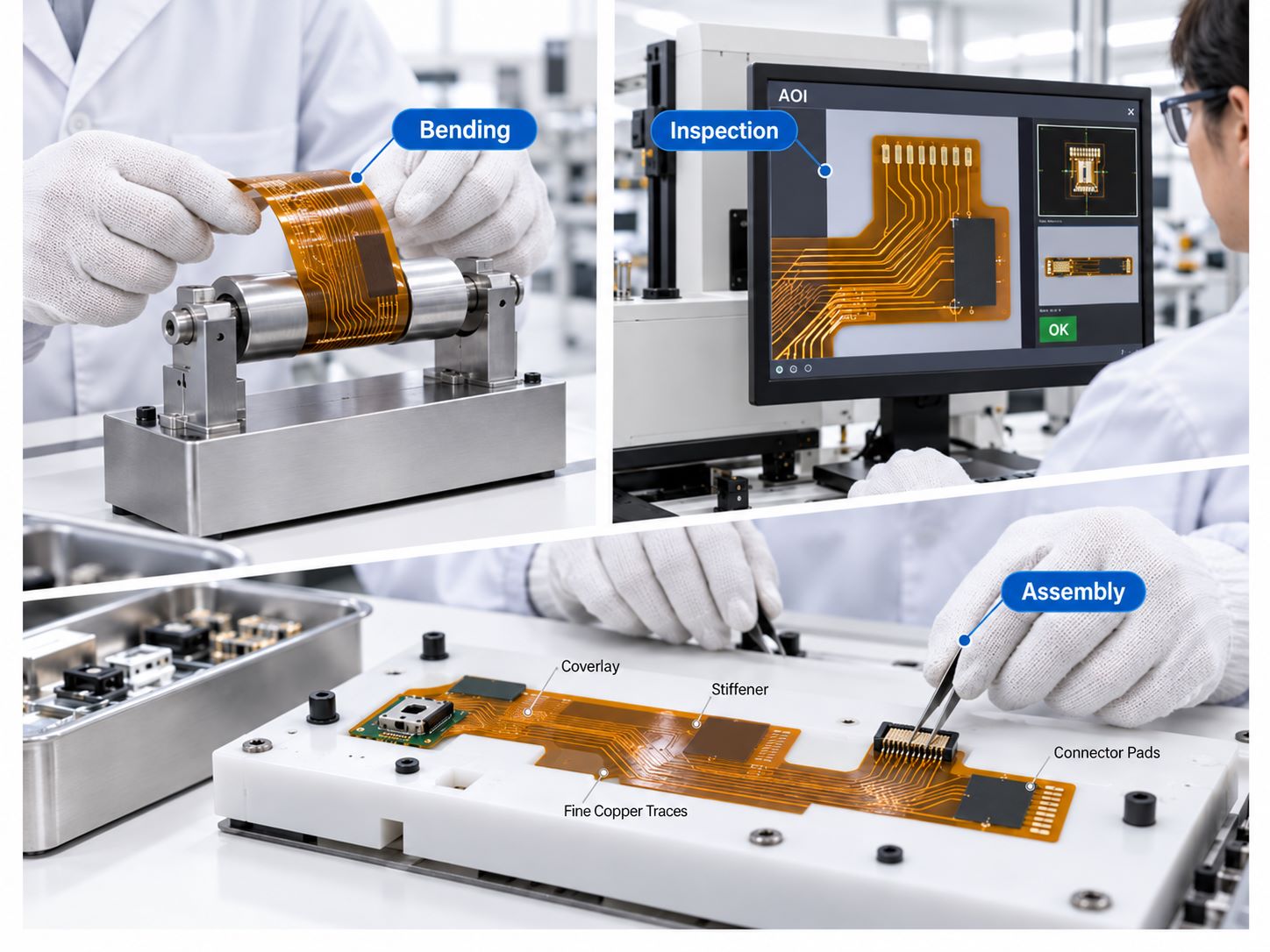
EBest Circuit Case Study: Custom Etched Flex Circuits for Compact Electronics

For one compact electronics project, EBest Circuit manufactured a 2-layer custom etched flex circuit designed for limited internal space and stable connection performance. The customer needed a thin FPC structure, reliable gold finger connection, local reinforcement, and controlled electrical resistance within the circuit path.

The project requirements included:

  • Circuit type: 2-layer FPC
  • Copper: 1/2oz rolled annealed copper
  • Base material: Adhesive-less flexible material
  • Finished board thickness: 0.1mm
  • Gold finger area: 0.35mm total thickness with stiffener
  • Surface finish: Immersion gold, 1Ī¼ā€
  • Stiffener design: 2 pcs Ɨ 1.0mm FR4 stiffener and 1 pc Ɨ 0.5mm FR4 stiffener
  • Printing: White ink on both sides
  • Electrical requirement: Resistance controlled between 30–70 ohms

The main challenge was to keep the circuit thin and flexible while strengthening the connector area. The 0.1mm main body helped the flex circuit fit into a compact enclosure. At the same time, the FR4 stiffeners provided mechanical support in selected areas, especially around the gold finger connection.
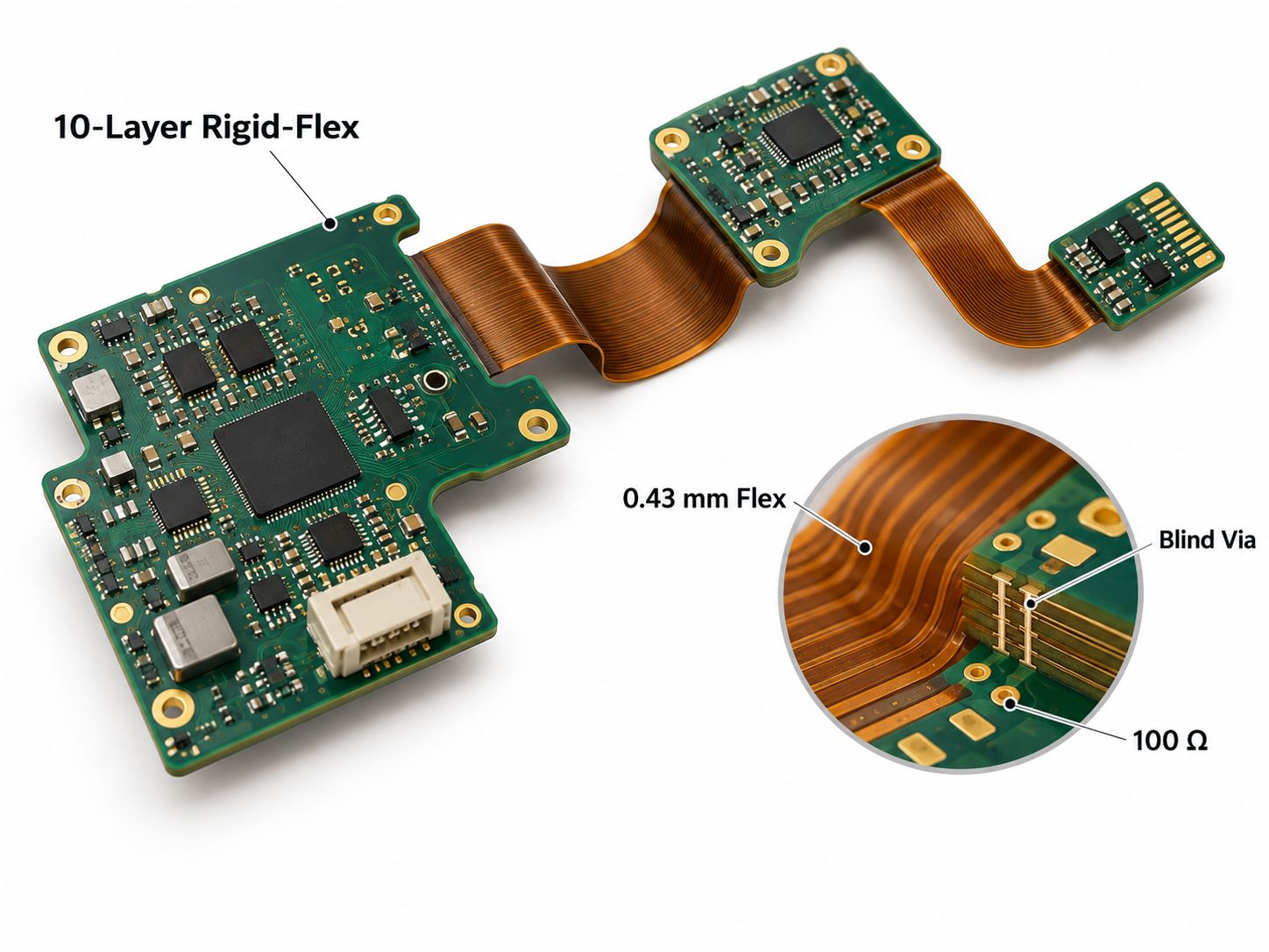
The use of 1/2oz rolled annealed copper helped improve flexibility compared with standard copper options. The adhesive-less base material also supported a thinner and more stable structure, which is important for compact electronics with bending or folding requirements.
To meet the customer’s assembly and appearance needs, EBest Circuit added double-sided white ink printing. This made the circuit easier to identify during assembly and helped match the product’s internal design requirements.

The resistance control requirement of 30–70 ohms also made this project more than a standard FPC order. Our engineering and production teams needed to pay attention to copper trace design, etching accuracy, and process consistency to keep the electrical performance within the required range.

This case shows how custom etched flex circuits can solve several design needs in compact electronics:

  • Save space inside a small enclosure
  • Reduce loose wiring and manual assembly
  • Keep the main circuit area thin and flexible
  • Strengthen connector and assembly areas with stiffeners
  • Support specific electrical resistance requirements
  • Improve product consistency from prototype to production

For EBest Circuit, the value of this project was not only making a flexible circuit. It was about balancing thin structure, bendability, connector strength, appearance, and electrical performance in one custom etched flex circuit design.

Why Choose EBest Circuit (Best Technology) for Custom Etched Flex Circuits?

Choosing the right manufacturer is important for custom etched flex circuits. The project usually involves more than simple PCB production. It needs engineering review, material selection, process control, and clear communication.

EBest Circuit, also known as Best Technology, supports customers with factory-direct manufacturing and engineering assistance. For custom etched flex circuit projects, we can help review design files, check manufacturability, suggest suitable materials, and support prototype or batch production.

Our advantages include:

Factory-direct production
Customers can communicate directly with the manufacturing team, which helps reduce delays and improve project efficiency.

Engineering support
We review key design details such as trace width, spacing, bend area, coverlay opening, and stiffener position before production.

Custom capability
We support different shapes, copper thicknesses, coverlay designs, stiffener materials, surface finishes, and connector areas.

Prototype to production support
Whether the project is in early design verification or ready for volume production, we can provide flexible manufacturing support.

Quality control
Electrical testing, dimensional inspection, and visual inspection help ensure that each batch meets the required standard.

For buyers who need custom etched flex circuits, EBest Circuit can provide both manufacturing service and practical engineering feedback. This helps reduce design risk and supports smoother production.

FAQs About Custom Etched Flex Circuits

What is a custom etched flex circuit?
A custom etched flex circuit is a flexible printed circuit made by etching copper traces on a flexible substrate, usually polyimide. It is designed according to a specific product layout.

What is the main benefit of using etched flex circuits?
The main benefit is compact and reliable interconnection. It can replace wires, save space, reduce weight, and simplify assembly.

Are custom etched flex circuits suitable for bending?
Yes. They are designed for bending and folding, but the bending radius, copper type, material thickness, and trace direction must be considered during design.

What material is commonly used for flex circuits?
Polyimide is the most common base material because it has good flexibility, heat resistance, and dimensional stability.

Can components be assembled on custom etched flex circuits?
Yes. Components can be assembled on flex circuits, but the design may need stiffeners or reinforced areas to support soldering and mechanical strength.

What surface finish is recommended for flex circuits?
ENIG is commonly used because it provides good flatness and oxidation resistance. Other finishes may also be selected based on cost and application.

What files are needed for a custom etched flex circuit quote?
Gerber files are usually required. A drawing, stack-up, material requirement, copper thickness, surface finish, quantity, and special notes are also helpful.

How can I reduce the cost of custom etched flex circuits?
Cost can be reduced by optimizing panel utilization, using suitable materials, avoiding unnecessary tight tolerances, and confirming the design before production.

Can EBest Circuit make prototypes before mass production?
Yes. EBest Circuit can support prototype production and help customers verify the design before moving to larger batch production.

Why should I choose EBest Circuit for custom etched flex circuits?
EBest Circuit provides factory-direct production, engineering review, custom manufacturing options, and quality control from prototype to production.

Custom etched flex circuits help compact electronic products become lighter, thinner, and easier to assemble, but reliable performance depends on the right material selection, including the use of a high-quality polyimide circuit board, as well as proper bend design, stiffener structure, surface finish, and process control. With 20 years of flexible circuit manufacturing experience, EBest Circuit supports customers from prototype to volume production with engineering review, fast-turn samples, and strict quality control. Send your Gerber files, drawings, or specifications to sales@bestpcbs.com for a fast engineering review and quotation.

You may also like

Top 10 Flexible Circuit Board Suppliers for Medical Devices

May 29th, 2026

Finding the right flexible circuit board suppliers for medical devices is not only about price. Medical electronics usually require compact design, stable quality, clean documentation, and reliable assembly support.

Flexible circuits are used in wearable monitors, hearing aids, diagnostic tools, imaging systems, catheter systems, and portable medical devices. This guide helps you quickly compare board types, design points, manufacturing capabilities, certifications, and supplier options. For project review or medical PCB assembly quotes, you can also send your Gerber files and BOM to sales@bestpcbs.com.

Flexible Circuit Board Suppliers for Medical Devices

What Are Flexible Circuit Boards for Medical Devices?

Flexible circuit boards are PCBs made with bendable materials, usually polyimide. They can fold, bend, or fit into small spaces where standard rigid PCBs are not practical.

For medical devices, flexible circuits help reduce wiring, save space, and improve internal structure. They are often used to connect sensors, displays, batteries, buttons, antennas, and control modules.

TypeTypical Use
Single-sided flex circuitsSimple medical interconnection
Double-sided flex circuitsMore routing space
Multilayer flex circuitsHigher signal density
Rigid flex circuit boardsCompact medical device structures
Custom etched flex circuitsSensor and special connection designs

Why Medical Flex Circuits Are Used in Medical Electronics?

Medical flex circuits are used because medical products are becoming smaller, lighter, and more integrated.

They help engineers:

  • Reduce cables and connectors
  • Save internal space
  • Improve assembly layout
  • Support curved or compact housings
  • Connect multiple functional areas
  • Build lightweight medical electronics

In many medical devices, the circuit must fit the product shape. That is where flex circuits and rigid-flex boards become practical.

What Types of Flexible Circuit Boards Are Used in Medical Devices?

EBest Circuit (Best Technology) supports several flexible PCB types for medical electronics projects.

Board TypeApplication Fit
Single-sided flexible circuitsSimple signal connection
Double-sided flexible circuitsMedium-density routing
Multilayer flexible circuitsCompact medical modules
Rigid flex circuit boardsIntegrated rigid + flexible structure
Custom flexible PCBDevice-specific mechanical design
Custom etched flex circuitsSensor, electrode, and special circuit paths
Flexible PCB with stiffenerConnector or SMT support
Medical PCB assembliesFabrication + component assembly

These board types are suitable for wearable devices, portable diagnostic equipment, handheld instruments, monitoring devices, and compact medical control modules.

Medical Device PCB Design: PCB Layout Guidelines for Flexible Circuits

Medical device PCB design should start from the product structure, not only the schematic.

Design AreaWhat to Check
Bend radiusAvoid sharp bending in flex areas
Trace routingUse smooth routing in bending zones
Component placementKeep parts away from active flex areas
ViasAvoid vias in repeated bending areas
Stiffener locationSupport connectors and SMT areas
GroundingImprove signal stability
ShieldingProtect sensitive medical signals
DFM reviewCheck manufacturability before production

For rigid flex circuit boards, the transition area between rigid and flex sections is especially important. Poor layout in this area can affect yield and reliability.

Custom Flexible PCB and Medical PCB Assembly Manufacturing Capabilities

EBest Circuit (Best Technology) provides comprehensive end-to-end solutions, from custom flexible PCB​ fabrication and rigid flex circuit boards​ integration to precision medical device PCB assembly services. Our operations are engineered specifically to meet the stringent reliability, miniaturization, and regulatory demands of the healthcare industry.

Core Capabilities in Medical-Grde Flex Circuits

As experts in medical flex circuits, we utilize advanced custom etched flex circuits​ technology to ensure superior performance:

  • Material Mastery:​ We utilize medical-grade polyimide (PI) and LCP substrates, ensuring full compliance with ISO 13485 and RoHS standards.
  • Precision Fabrication:​ Our capabilities include fine-line trace routing and micro-via technology, perfect for the compact medical device PCB design​ required in modern implants and wearables.
  • Rigid-Flex Solutions:​ We seamlessly integrate flex circuits​ with rigid sections, providing 3D packaging solutions that reduce weight and improve signal integrity for critical medical electronics.

Excellence in Medical PCB Assembly

Being a trusted medical PCB manufacturer​ means we never compromise on quality. Our medical PCB assembly​ processes are designed for zero-defect outcomes:

  • Advanced Assembly:​ We offer high-precision SMT, BGA/CSP placement, and medical electronics assembly​ with sterilization-resistant coatings.
  • Quality Assurance:​ Our medical PCB assembly services​ include 100% AOI/X-ray inspection and functional testing, aligning with FDA and GMP requirements.
  • Full-System Integration:​ From prototype to volume production of medical PCB assemblies, we manage the entire lifecycle, including box-build integration.

Ready to start your next medical electronic assembly project? Just feel free to contact EBest Circuit (Best Technology)​ at sales@bestpcbs.com​ for expert support with your custom flexible PCB​ and medical PCB assemblies.

Certifications for Medical PCB Manufacturing and Assembly

Certifications help customers screen medical PCB suppliers faster.

Certification / StandardWhy It Matters
ISO 9001General quality management
ISO 13485Medical device quality management
IPC standardsPCB fabrication and assembly workmanship
RoHS / REACHMaterial compliance for global markets
UL materialsRequired for some product designs

For high-reliability medical electronics, IPC Class 3 is often discussed during flex PCB manufacturing review.

Medical Applications Using Rigid Flex Circuit Boards

Rigid flex circuit boards are used when a medical device needs both mechanical support and flexible connection.

ApplicationWhy Rigid-Flex Helps
Wearable monitorsThin, light, body-friendly structure
Hearing aidsCompact curved internal layout
EndoscopesNarrow and flexible circuit path
Catheter systemsLong, thin, flexible connection
Portable diagnostic toolsReduced cables and smaller housing
Imaging equipmentStable signal routing
Surgical instrumentsCompact and durable internal design
Patient monitoring devicesIntegrated sensor and control connection

Case Study: EBest Circuit (Best Technology) Manufacturing Medical Flex Circuits

Project Type:
2-layer medical FPC for compact medical electronics.

Customer Requirement:
The customer needed a thin, flexible circuit with steel stiffeners on both sides for better assembly support.

EBest Circuit (Best Technology) Support:

  • Reviewed FPC stack-up and material structure
  • Checked coverlay opening and solder mask design
  • Controlled steel stiffener alignment
  • Used ENIG finish for stable solderability
  • Added white silkscreen markings for UL 94 V-0 and RoHS
  • Controlled bonding with 0.025mm pure thermal adhesive

Manufacturing Focus:
Thin FPC structure, stiffener bonding, flatness control, coverlay registration, and final surface quality.

Board Parameters

ItemSpecification
Board Type2-layer FPC
Board Thickness0.16mm ±0.03mm
Copper Type1/2 oz ED Cu
Base Material1 mil adhesive PI
Coverlay1 mil yellow coverlay
Surface FinishENIG 2U”
Solder MaskGreen solder mask
SilkscreenWhite silkscreen
Compliance MarkingUL 94 V-0, RoHS
Top Stiffener0.2mm steel stiffener
Bottom Stiffener0.2mm steel stiffener
Stiffener Adhesive0.025mm pure thermal adhesive
Key Control PointsStiffener alignment, bonding strength, flatness, coverlay registration

Top 10 Flexible Circuit Board Suppliers for Medical Devices

Below are 10 suppliers commonly found when researching medical flex circuits, rigid-flex PCBs, and medical PCB assembly services.

Company NameCertificationsKey Capabilities
EBest Circuit (Best Technology)ISO 9001, ISO 13485, UL, RoHSMedical flex circuits, rigid-flex PCB, medical PCB assembly, DFM review
Epec Engineered TechnologiesISO, UL, IPCMedical flex PCB, rigid-flex PCB, reliability testing
FralockISO 13485, ISO 9001, AS9100D, FDA registeredFlex circuits, rigid-flex, stiffeners, shielding, turnkey builds
BENCORISO 9001, ULFlexible PCB, rigid-flex PCB, design, fabrication, assembly
Rush PCBISO 9001, ISO 13485, UL, RoHS/REACHFlex PCB, rigid-flex PCB, medical PCB assembly, quick-turn service
All Flex SolutionsAS9100, ISO 9001, ESD S20.20Flexible circuits, CatheterFlex, rigid-flex, medical device PCBs
MincoISO 9001, AS9100D, NadcapHigh-reliability flex circuits, rigid-flex, multilayer flex
Cirexx InternationalISO 9001, AS9100, ITAR, IPCFlex PCB, rigid-flex PCB, layout, fabrication, assembly
Flex Plus FPCISO 9001, ISO 13485, IATF 16949, ULMedical FPC, hearing aid FPC, portable monitor FPC
HT Medical DevicesISO 13485, FDA registered product buildsFlexible circuits, rigid-flex, catheter flex, endoscope flex

Before choosing a supplier, compare certifications, flex PCB capability, assembly support, traceability, quote speed, and engineering communication.

How to Choose Flexible Circuit Board Suppliers for Medical Devices

Use this checklist before sending a medical PCB project to a supplier:

CheckpointWhy It Matters
Medical PCB experienceReduces communication risk
Flex and rigid-flex capabilitySupports more device structures
ISO 13485Important for medical supply chains
DFM supportFinds layout issues early
SMT assemblySaves supplier coordination time
Component sourcingSupports one-stop medical electronics assembly
Testing capabilityImproves delivery confidence
TraceabilityHelps audits and production records
Fast RFQ responseSpeeds up project evaluation

A strong supplier should not only quote. They should review your files and point out manufacturing risks.

Future Trends of Custom Flexible PCB for Medical Devices

Custom flexible PCB will continue to grow in medical electronics because devices are getting smaller and more wearable.

Key trends include:

  • More wearable medical monitors
  • More rigid-flex designs in compact devices
  • Smaller sensor modules
  • Higher-density routing
  • Better signal shielding
  • Stronger traceability requirements
  • More demand for one-stop PCB + assembly service
  • Earlier DFM review before production

For medical device developers, this means the PCB supplier should join the project earlier, not only after the design is finished.

FAQs About Flexible Circuit Board Suppliers for Medical Devices

Q1. What are flexible circuit board suppliers for medical devices?
They are PCB manufacturers that provide flex circuits, rigid-flex boards, and sometimes medical PCB assembly for medical electronics.

Q2. What are medical flex circuits used for?
They are used in wearable monitors, hearing aids, diagnostic devices, imaging systems, catheter systems, and compact medical electronics.

Q3. What is the difference between flex circuits and rigid flex circuit boards?
Flex circuits are bendable boards. Rigid flex circuit boards combine rigid PCB areas and flexible connection areas in one design.

Q4. Can custom flexible PCB be used in wearable medical devices?
Yes. It helps reduce size, weight, and wiring inside wearable medical products.

Q5. What files are needed for medical PCB assembly quotes?
Usually Gerber files, BOM, pick-and-place file, assembly drawing, testing requirements, quantity, and material requirements.

Q6. What should be checked in medical device PCB design?
Bend radius, trace routing, stiffener position, connector support, component placement, surface finish, and DFM feedback.

Q7. Why is ISO 13485 important?
It shows the supplier has a medical device quality management system.

Q8. Can flexible circuits support SMT assembly?
Yes. Components are usually mounted on rigid or reinforced areas to improve assembly stability.

Q9. What affects medical PCB assembly cost?
Layer count, material, size, copper thickness, surface finish, components, assembly difficulty, testing, and order quantity.

Q10. Does EBest Circuit (Best Technology) provide medical PCB assembly services?
Yes. EBest Circuit (Best Technology) supports flex PCB fabrication, rigid-flex PCB manufacturing, component sourcing, SMT assembly, DFM review, testing, and medical PCB assembly services.

In conclusion, choosing flexible circuit board suppliers for medical devices should be based on capability, quality control, medical experience, and engineering support.

EBest Circuit (Best Technology) provides custom flexible PCB, rigid flex circuit boards, medical flex circuits, medical PCB assembly, DFM review, component sourcing, and testing support. Pls feel free to send your Gerber files, BOM, drawings, and project requirements to sales@bestpcbs.com for a medical PCB assembly quote.

You may also like

What is IPC-6013 Standard? IPC 6012 vs IPC-6013

May 12th, 2026

What is IPC-6013 and how does it differ from IPC 6012 for printed circuit board manufacturing? For professionals working with flexible and rigid flex PCBs, understanding IPC-6013 is key to ensuring product reliability and avoiding production errors. This guide breaks down IPC-6013’s core definitions, classifications, manufacturing guidance, and direct comparisons with IPC 6012 to resolve common project pain points.

IPC-6013, https://www.bestpcbs.com/blog/2026/05/ipc-6013/

What is the IPC-6013 Standard?

IPC-6013 is a globally recognized industry standard from the IPC, outlining qualification and performance requirements for flexible and rigid flex printed circuit boards. It addresses the unique challenges of flexible circuits, such as bending, folding, and mechanical stress, while ensuring consistent electrical performance.

The standard establishes uniform criteria for material selection, manufacturing processes, electrical testing, and quality control. It ensures consistency across production batches, aligning manufacturers, designers, and buyers on flexible circuit performance expectations. Without IPC-6013, flexible PCB production lacks standardized quality benchmarks, leading to inconsistent reliability and higher field failure risks.

IPC-6013 applies to all flexible circuit types, single-layer, double-layer, multi-layer, and rigid flex combinations. It is widely adopted in consumer electronics, automotive, aerospace, and medical devices, where flexible circuits enable compact, dynamic product designs.

What Are Types of IPC-6013?

IPC-6013 is categorized primarily by performance classes which dictate the quality and reliability requirements for different applications. These classes are designed to match the specific needs of various industries ensuring that flexible circuits meet the necessary standards without over engineering or unnecessary cost:

  • IPC 6013 Class 1: This is the entry level class for flexible circuits intended for non critical applications where basic functionality is the primary requirement. It allows for minor cosmetic defects and lower performance thresholds making it suitable for low cost consumer products with short service lives.
  • IPC 6013 Class 2: A mid tier class focused on reliable performance for dedicated service applications. It imposes stricter quality controls than Class 1 including tighter tolerances for conductor width spacing and solderability. This class is widely used in industrial and automotive electronics where consistent performance over extended periods is necessary.
  • IPC 6013 Class 3: The highest performance class for critical applications where failure could result in significant consequences such as injury equipment damage or loss of life. It requires the most stringent manufacturing controls testing and quality assurance measures making it ideal for aerospace medical and military applications.

What is IPC 6013 Class 2 and What Applications is it Suitable for?

IPC 6013 Class 2 balances reliability and cost, making it the most common choice for industrial and commercial flexible PCBs. It defines clear requirements for conductor integrity, insulation quality, solderability, and mechanical durability, ensuring consistent performance in demanding but non-critical environments.

  • Conductor and Insulation Tolerances: Strict limits for conductor width, spacing, and minimum copper thickness, ensuring electrical integrity under normal operating conditions.
  • Environmental Resistance: Requirements to withstand temperature fluctuations, humidity, and chemical exposure common in industrial and commercial settings.
  • Electrical Testing: Mandatory continuity, insulation resistance, and dielectric strength tests to verify performance and identify potential defects.
  • Automotive Electronics: Dashboard controls, sensor modules, and in-car communication systems that require reliable performance in varying temperatures.
  • Industrial Control Systems: Equipment used in manufacturing, automation, and process control, where long-term reliability is critical.
  • 5G Communication Devices: Compact, flexible components for smartphones, routers, and other wireless equipment.
  • Non-Life-Support Medical Devices: Diagnostic tools, wearable health monitors, and other medical equipment that does not directly impact patient safety.

What is IPC 6013 Class 3 and How Does it Differ from Class 2?

IPC 6013 Class 3 is the highest performance classification for critical flexible PCB applications, with stricter requirements than Class 2. The table below clearly outlines the key differences between the two classes, along with core details of Class 3.

CategoryIPC 6013 Class 2IPC 6013 Class 3
Performance LevelMid-tier, balanced reliability and cost for non-critical dedicated service applicationsHighest tier, designed for critical applications where failure has severe consequences
TolerancesTighter than Class 1, with reasonable allowances for conductor width, spacing, and copper thicknessStrictest tolerances, eliminating even minor defects acceptable in Class 2
Testing RequirementsThorough electrical testing (continuity, insulation resistance, dielectric strength)Rigorous testing including environmental stress, thermal cycling, and vibration testing
Defect AllowancesMinor cosmetic defects are acceptable as long as they do not impact performanceNo defects (scratches, cracks, voids) that could affect performance are permitted
Documentation & TraceabilityStandard documentation of manufacturing processes and test resultsComprehensive documentation and full traceability of all components and process steps
Typical ApplicationsAutomotive electronics, industrial control systems, 5G devices, non-life-support medical toolsAerospace components, military equipment, life-support medical devices, deep-sea exploration gear
CostModerate, cost-effective for commercial and industrial use30-50% higher than Class 2, justified by critical performance needs
IPC-6013, https://www.bestpcbs.com/blog/2026/05/ipc-6013/

Is there an IPC 6013 Class 3A and What Specifications Does it Include?

No, official IPC 6013 Class 3a classification exists under IPC standards. Confusion around Class 3a often comes from misinterpreting IPC guidelines or custom manufacturer requirements. IPC-6013 only recognizes three official classes: Class 1, Class 2, and Class 3.

  • Informal “Class 3a” Use: Some industries or manufacturers use the term informally to describe Class 3 circuits with additional custom specifications.
  • Custom Specifications: These may include specialized materials, enhanced environmental resistance, or unique testing protocols for niche applications like aerospace or military use.
  • Avoid Official Use: “Class 3a” is not part of the official IPC-6013 standard, so avoid using it when referencing compliance.
  • Document Custom Requirements: Clearly outline any additional specifications separately from IPC-6013’s official classes.
  • Verify Compliance: Always reference IPC-6013’s official classes (1, 2, 3) and work with manufacturers to document custom needs.

What is the Latest Revision of IPC-6013 and What Changes Does it Bring?

The latest revision of IPC-6013 is Revision C, released in December 2013. It updated Revision B to address advances in flexible circuit technology and emerging industry needs, ensuring the standard remains relevant for modern manufacturing.

  • High-Density Circuit Requirements: Tighter tolerances for fine-pitch conductors and microvias, addressing demand for smaller, more compact flexible circuits in consumer electronics and medical devices.
  • Updated Material Guidelines: New flexible substrate materials and adhesives with improved performance and durability.
  • Lead-Free Solder Guidance: Alignment with global environmental regulations like RoHS, providing clear guidelines for lead-free manufacturing.
  • Enhanced Testing Procedures: More detailed protocols for environmental stress testing and mechanical durability, ensuring circuits withstand real-world conditions.
  • Rigid Flex Clarification: Detailed guidance on the interface between rigid and flexible sections, ensuring rigid flex circuits meet the same performance standards as fully flexible circuits.

How Does IPC-6013 Guide Flexible Circuit Manufacturing?

IPC-6013 guides every stage of flexible circuit manufacturing, addressing unique challenges like material handling and mechanical stress to ensure consistent, high-quality products.

  • Material Selection: IPC-6013 specifies the acceptable types of substrates adhesives and conductors for flexible circuits. It defines requirements for substrate thickness copper foil weight and insulation properties ensuring that materials can withstand bending and environmental stress without degrading.
  • Manufacturing Process Controls: The standard outlines strict controls for processes such as etching lamination and drilling. It specifies the acceptable parameters for each process including temperature pressure and time to ensure consistent results across production batches.
  • Conductor and Insulation Requirements: IPC-6013 defines the minimum requirements for conductor width spacing and thickness as well as insulation thickness and dielectric strength. These requirements ensure that flexible circuits maintain electrical performance even when bent or flexed.
  • Surface Finish Requirements: The standard provides guidance on acceptable surface finishes for flexible circuits including solder mask and conformal coating. It specifies the requirements for surface finish thickness adhesion and resistance to environmental factors.
  • Testing and Inspection: IPC-6013 mandates a range of tests to verify the performance and quality of flexible circuits. These tests include continuity testing insulation resistance testing dielectric strength testing and mechanical durability testing such as bending and flexing tests.

What is the Difference between IPC 6012 and IPC-6013?

IPC 6012 and IPC-6013 serve distinct purposes, focusing on rigid and flexible/rigid flex PCBs respectively. The table below compares the two standards across key categories.

CategoryIPC 6012IPC-6013
Primary FocusRigid printed circuit boards including HDI and standard rigid PCBsFlexible and rigid flex printed circuit boards
Core ApplicationApplications where PCBs remain rigid such as computers industrial equipment and automotive control unitsApplications requiring bending folding or dynamic movement such as wearables medical devices and aerospace components
Material RequirementsFocuses on rigid substrates such as FR-4 with strict requirements for thickness flatness and thermal stabilityFocuses on flexible substrates such as PI and PET with requirements for flexibility durability and resistance to mechanical stress
Mechanical RequirementsNo requirements for flexibility or bending resistance focuses on rigidity and flatnessStrict requirements for bending flexing and mechanical durability including minimum bend radius and flex cycle life
Testing ProtocolsTests focus on electrical performance thermal stability and mechanical rigidityTests include bending flexing and environmental stress testing in addition to standard electrical performance tests

How Do IPC 6012 and IPC-6013 Differ in Terms of Performance Requirements?

The performance requirements of IPC 6012 and IPC-6013 differ significantly due to their focus on rigid vs. flexible PCBs. Below are the key differences in performance criteria.

  • Electrical Performance: IPC 6012 focuses on electrical performance for rigid PCBs including impedance control signal integrity and copper conductivity. It sets strict requirements for conductor resistance insulation resistance and dielectric strength. IPC-6013 includes similar electrical performance requirements but also addresses the impact of bending and flexing on electrical performance ensuring that flexible circuits maintain signal integrity even when deformed.
  • Mechanical Performance: IPC 6012 has no requirements for flexibility or bending resistance as rigid PCBs are not designed to bend. It focuses on mechanical rigidity flatness and resistance to thermal expansion. IPC-6013 places heavy emphasis on mechanical performance including minimum bend radius flex cycle life and resistance to fatigue from repeated bending.
  • Environmental Performance: Both standards include requirements for environmental resistance but IPC-6013 adds specific requirements for flexible circuits such as resistance to moisture absorption and chemical exposure during bending. IPC 6012 focuses on environmental resistance for rigid PCBs including thermal shock and humidity resistance.
  • Quality Control: IPC 6012 requires quality control measures focused on maintaining the rigidity and flatness of PCBs including inspection for warpage and delamination. IPC-6013 requires additional quality control measures to ensure that flexible circuits do not develop cracks tears or other defects during manufacturing or use.

When Should you Use IPC 6012 Instead of IPC-6013 for Printed Board Projects?

Choosing between IPC 6012 and IPC-6013 depends on project needs like PCB type, cost, and application. The following points outline when IPC 6012 is the better choice.

  • Use IPC 6012 when the project requires rigid PCBs that will not be bent folded or subjected to mechanical stress. Rigid PCBs are ideal for applications where stability and flatness are critical such as motherboards industrial control panels and automotive engine control units.
  • Use IPC 6012 when cost is a primary concern. Rigid PCBs manufactured to IPC 6012 standards are typically less expensive than flexible circuits manufactured to IPC-6013 standards due to simpler materials and manufacturing processes.
  • Use IPC 6012 for high density applications that do not require flexibility. IPC 6012 includes detailed requirements for HDI rigid PCBs which are ideal for applications such as smartphones and computers where space is limited but flexibility is not needed.
  • Use IPC 6012 when the application does not require dynamic movement. If the PCB will remain stationary throughout its service life IPC 6012 provides the necessary standards to ensure reliability without the additional requirements of IPC-6013.
  • Use IPC 6012 for applications that require high thermal stability. Rigid PCBs manufactured to IPC 6012 standards are designed to withstand high temperatures making them suitable for applications such as power supplies and industrial heating systems.

How to Ensure Compliance with IPC-6013 Standards in Production?

Maintaining IPC-6013 compliance requires careful control of materials, processes, and testing. Below are actionable steps to ensure production meets the standard’s requirements.

  • Select Qualified Materials: Use only materials that meet the requirements specified in IPC-6013 including flexible substrates adhesives and conductors. Verify material certifications and test samples to ensure they meet the standard’s specifications.
  • Implement Process Controls: Establish strict process controls for all manufacturing steps including etching lamination drilling and surface finishing. Monitor process parameters such as temperature pressure and time to ensure consistency and compliance.
  • Conduct Regular Testing: Perform all required tests outlined in IPC-6013 including electrical testing mechanical testing and environmental testing. Implement a regular testing schedule to verify that production batches meet the standard’s requirements.
  • Train Production Personnel: Ensure all production personnel are trained on IPC-6013 requirements and understand the importance of compliance. Provide ongoing training to keep personnel updated on any changes to the standard.
  • Implement Quality Assurance Systems: Establish a quality assurance system to monitor and document all production processes. Maintain detailed records of material certifications process parameters and test results to ensure traceability and compliance.
  • Work with Certified Manufacturers: Partner with manufacturers that are certified to produce flexible circuits to IPC-6013 standards. Verify their certification and ask for documentation of past compliance to ensure they can meet the standard’s requirements.

Where Can You Find a Reliable IPC-6013 PDF Document?

Accessing a reliable IPC-6013 PDF is crucial for ensuring compliance. The following sources provide authentic, up-to-date copies of the standard.

  • Official IPC Website: The IPC website offers the latest revision of IPC-6013 as a downloadable PDF. This is the most reliable source for the official standard as it ensures you have the most up to date and accurate information.
  • Authorized IPC Distributors: Authorized distributors of IPC standards often provide downloadable PDF versions of IPC-6013. These distributors are certified by the IPC ensuring that the documents they provide are authentic and unmodified.
  • Industry Associations: Many electronics industry associations provide access to IPC standards including IPC-6013 for their members. These associations often offer discounted access to standards for members making it an affordable option.
  • Certified Manufacturing Partners: Manufacturers certified to produce flexible circuits to IPC-6013 standards often have a copy of the standard available for their clients. They can provide a PDF version or direct you to a reliable source.
  • Educational Institutions: Technical colleges and universities with electronics engineering programs often have access to IPC standards including IPC-6013. Students and faculty may be able to access the PDF through the institution’s library.
 IPC-6013, https://www.bestpcbs.com/blog/2026/05/ipc-6013/

FAQ About IPC-6013 and IPC 6012

Q1: Can I use IPC 6012 standards for flexible PCBs?

A1: No, IPC 6012 is designed exclusively for rigid PCBs and does not address flexible circuit requirements. Using it for flexible PCBs risks non-compliance and compromised durability. Always use IPC-6013 for flexible and rigid flex PCBs.

Q2: Is IPC-6013 required for all flexible PCB projects?

A2: While not legally mandatory, IPC-6013 is the industry’s recognized standard for flexible PCBs. Most manufacturers, buyers, and regulators require compliance to ensure reliability. Skipping it increases failure risks and lost business.

Q3: What is the cost difference between IPC 6013 Class 2 and Class 3?

A3: Class 3 flexible circuits cost 30-50% more than Class 2. The premium comes from stricter manufacturing controls, rigorous testing, and higher-quality materials—justified for critical applications where failure is unacceptable.

Q4: How often is IPC-6013 updated?

A4: IPC-6013 is updated periodically to reflect technology advancements. The last major revision was Revision C in 2013. Check the official IPC website regularly for the latest updates.

Q5: Can I mix IPC 6012 and IPC-6013 requirements for rigid flex PCBs?

A5: No, rigid flex PCBs must follow IPC-6013, which includes specific guidelines for the rigid-flex interface. While IPC 6012 may offer general rigid PCB guidance, IPC-6013 is the primary standard for all rigid flex production.

You may also like