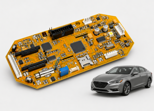
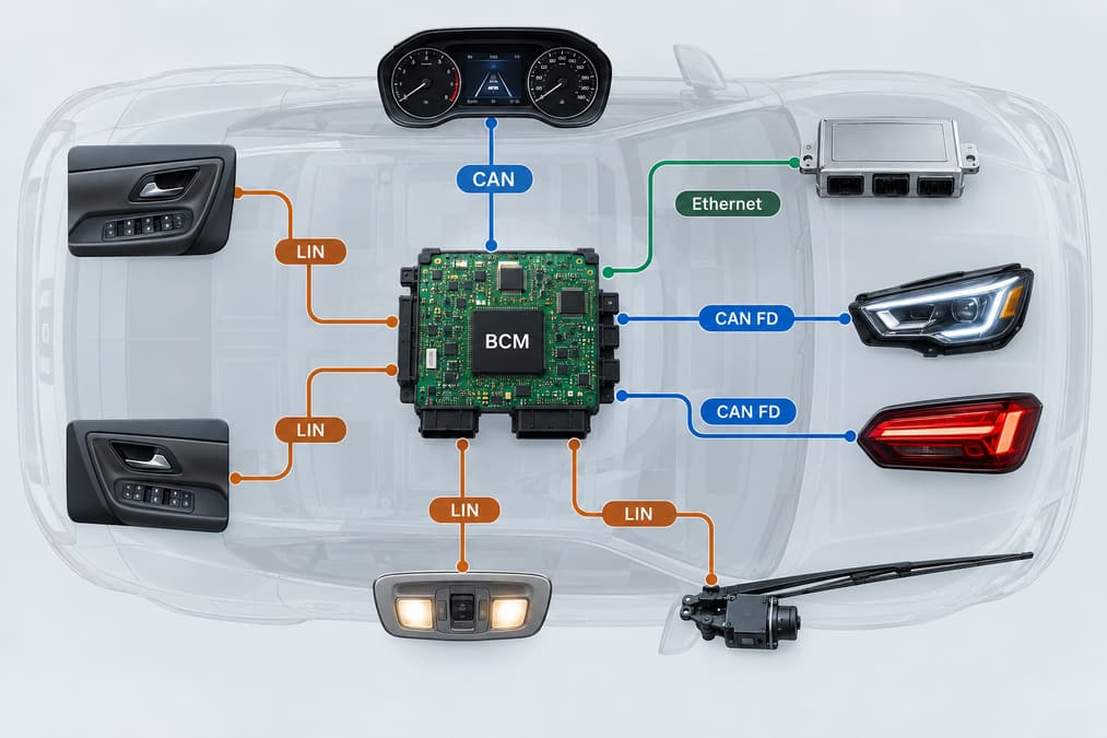
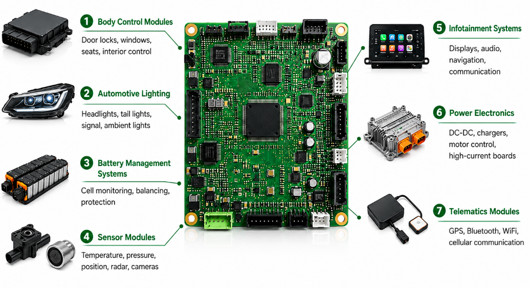
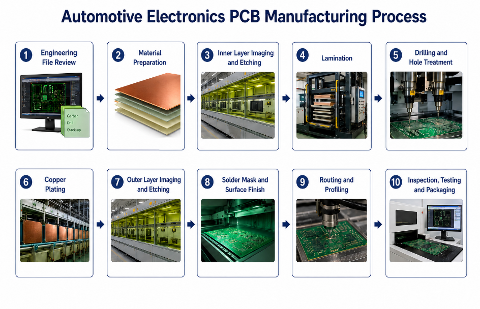
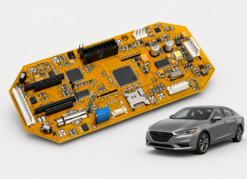
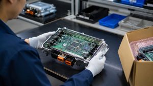
CAN bus vs LIN bus comes down to how devices share information, how quickly they exchange it, and how much hardware each connection needs. CAN lets multiple electronic control units send messages using priority arbitration. LIN uses one coordinating node to schedule communication with simpler sensors and actuators. These differences explain why vehicles often use both networks.
EBest Circuit provides PCB fabrication, component sourcing, and PCB assembly for customer-designed control and interface boards. For CAN or LIN hardware, these services support the build from bare PCB to assembled board. Discuss your prototype or production needs with sales@bestpcbs.com.
What Is the Difference Between LIN and CAN Bus?
CAN allows nodes to compete for bus access; LIN gives one node control of the communication schedule. That distinction shapes their hardware, timing, and typical applications.
CAN stands for Controller Area Network. LIN stands for Local Interconnect Network. In LIN, the coordinating node is called the commander, or master in older documentation.
Main difference
CAN bus
LIN bus
Who starts communication?
Multiple nodes can initiate messages when the bus is available
One commander sends scheduled frame headers
How is access organized?
Higher-priority messages win arbitration
Devices respond in the assigned frame slots
Where is it commonly used?
Communication between vehicle control units
Local connections to simpler sensors and actuators
This article compares conventional two-wire high-speed CAN with automotive LIN. Specialized CAN physical layers are outside its scope.
How Does CAN/LIN Communication Work?
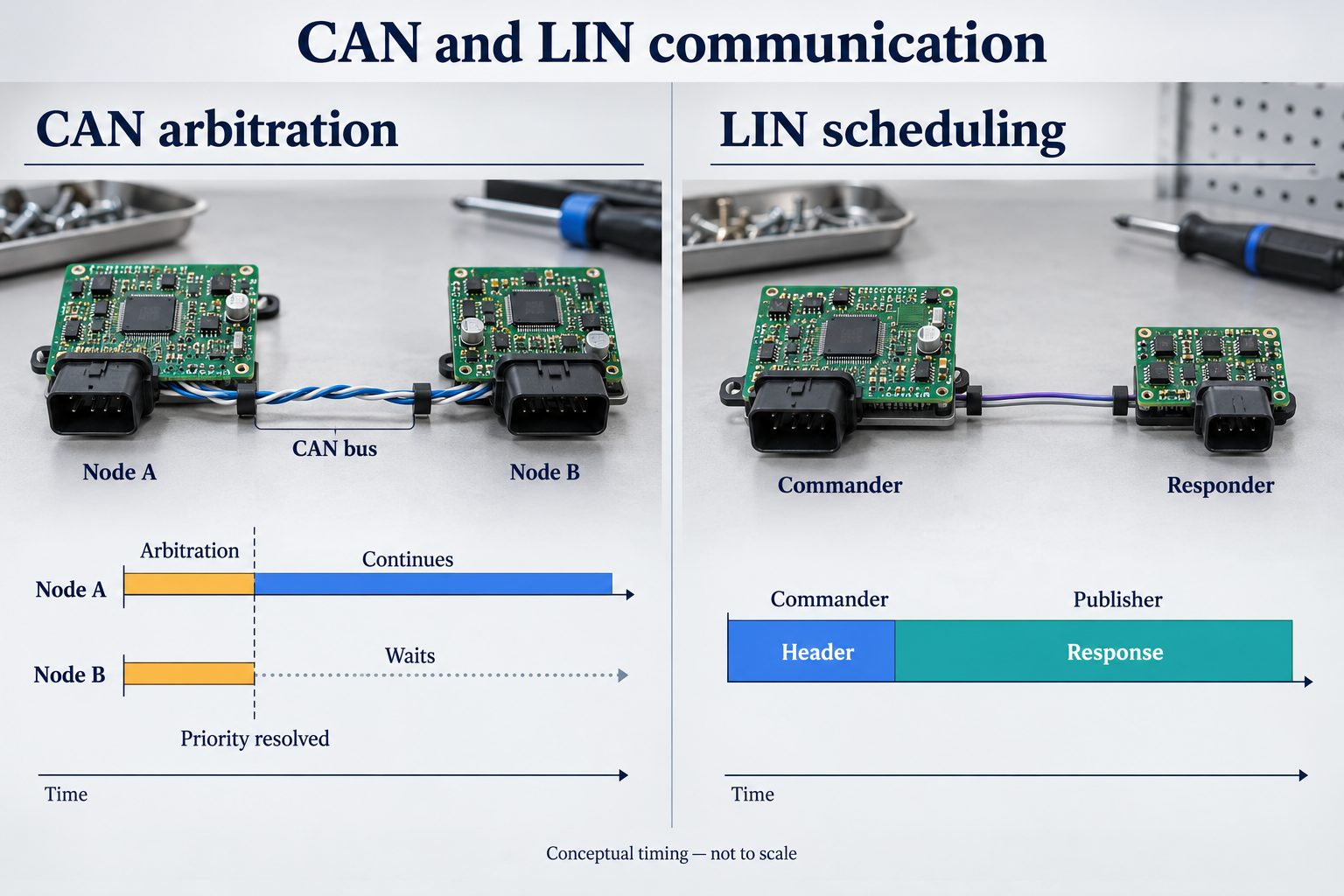
CAN determines which waiting message goes first. LIN determines when each scheduled exchange happens.
CAN: the higher-priority message continues.
A node starts transmitting when the bus is available.
If another node starts at the same time, both monitor the bus while sending their arbitration fields.
The node that loses arbitration stops transmitting. The winning message continues, and the waiting node can try again later.
Arbitration works because a dominant bit overrides a recessive bit on the bus. A node that sends recessive but reads dominant knows it has lost. For otherwise comparable data frames with the same identifier format, a lower numerical identifier has higher priority.
LIN: the commander starts each exchange.
The commander sends a header identifying the scheduled frame.
The designated publisher sends the data and checksum in the response.
Nodes that need those signals receive and use the response.
The publisher can be another node or the commander itself. A response can also be used by other devices in the same LIN cluster; it does not have to travel only back to the commander.
How Do CAN and LIN Bus Speeds Compare?
Classical CAN supports a much higher maximum bit rate than LIN. CAN FD can increase data transfer capacity further.
LIN: up to 20 kbit/s, with 1–8 data bytes per frame.
Classical CAN: up to 1 Mbit/s, with up to 8 data bytes per frame.
CAN FD: up to 64 data bytes per frame, with the option to use a faster bit rate during the data phase. Arbitration still uses the nominal bit rate.
The maximum raw bit-rate ratio between Classical CAN and LIN is 50:1. However, bit rate is not the same as device update rate.
For example, an eight-data-byte LIN frame takes approximately 6.2 ms at 20 kbit/s before additional spacing. A sensor whose frame appears once in a longer repeating schedule must wait for its next slot. Its reading therefore does not necessarily update every 6.2 ms.
CAN messages can also wait while other traffic uses the bus. Actual response time depends on bus loading and message priority. For CAN FD, the usable data-phase rate additionally depends on the controllers, transceivers, wiring, and network configuration.
How Do CAN and LIN Electrical Interfaces Differ?
CAN uses two differential signal lines; LIN uses one signal line referenced to ground. Their transceivers and bus circuits are different, so the interfaces cannot be directly substituted.
Pull-up network; the commander normally includes an external resistor and diode
Interface to the MCU
CAN controller functionality plus a CAN transceiver
LIN-capable communication, often using a UART, plus a LIN transceiver
On CAN, differential reception helps reject interference that appears similarly on both lines. Ground differences still matter: the transceiver must stay within its allowed common-mode voltage range.
On LIN, the transmitter pulls the signal low for a dominant state. Pull-ups let it rise toward the bus supply for a recessive state. The transceiver connects this bus-side signaling to the MCU’s logic interface; a UART pin cannot connect directly to an automotive LIN wire.
For the circuit board, the difference extends beyond connector pins. Transceivers, resistor networks, and protection circuits must suit the bus. The signal-wire counts above also exclude power and ground connections.
Why Is LIN Usually Cheaper to Implement Than CAN?
LIN can reduce the cost of connecting devices that exchange only small amounts of data. The savings mainly come from the wiring and the communication hardware:
Fewer signal connections: one LIN signal wire can reduce harness conductors and connector contacts compared with a two-wire CAN connection.
Simple MCU communication hardware: a low-cost MCU’s UART can support LIN with suitable software and a LIN transceiver.
Timing synchronization: the LIN header’s synchronization field lets compatible responder implementations align their communication timing with the commander.
The cost advantage varies with the existing hardware. If a control unit already has an MCU with an integrated CAN controller, using CAN may not require an additional controller chip.
Power regulation, transient protection, connectors, and testing still contribute to either board’s cost. A simple LIN actuator and a CAN-equipped control unit therefore cannot be compared using one universal savings percentage.
Why Do Vehicles Use Both CAN and LIN?
CAN can connect vehicle controllers while LIN handles smaller local groups of devices. This gives each part of the system communication capacity suited to its workload.
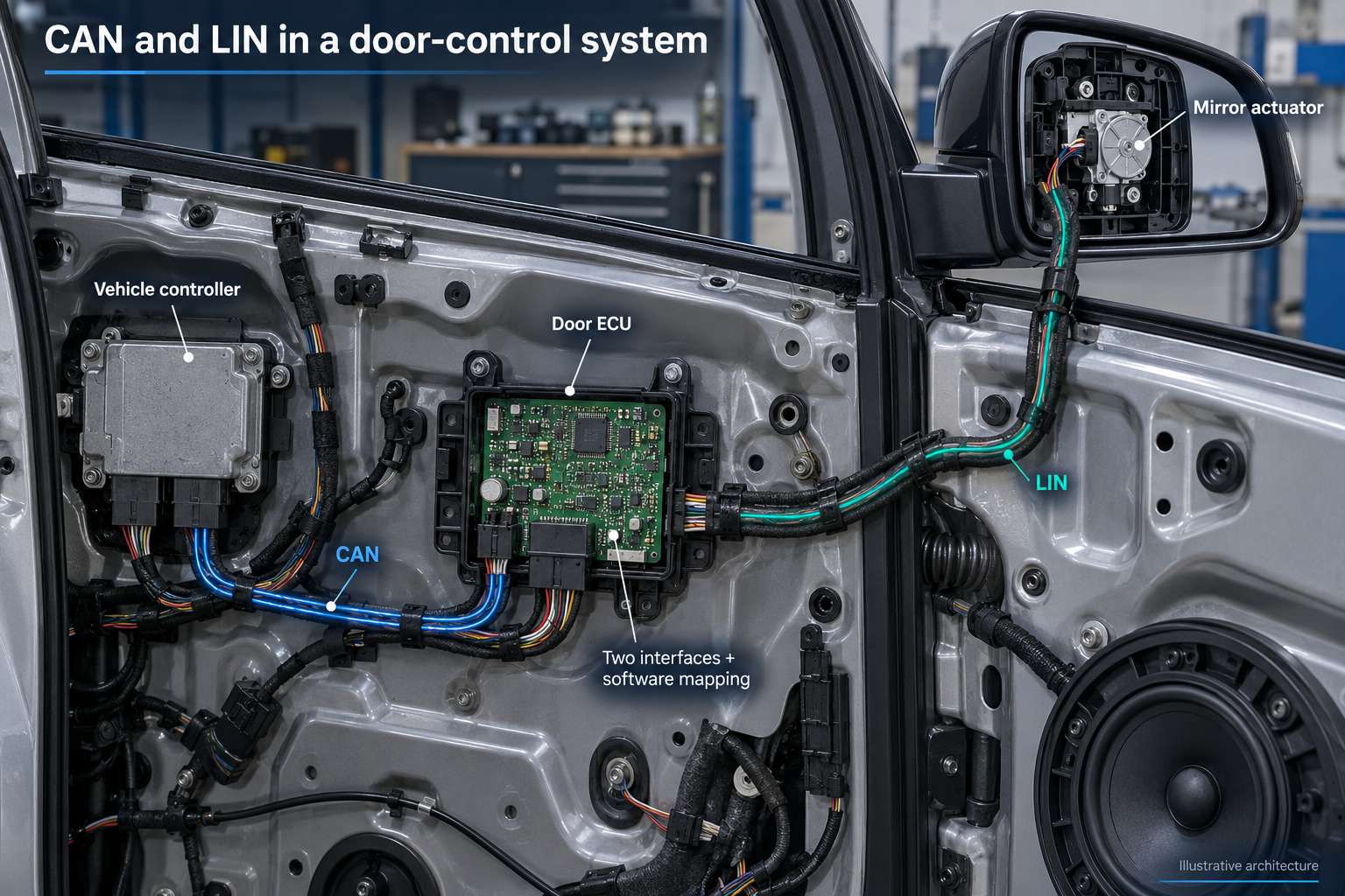
An illustrative door-control arrangement shows how they work together:
Vehicle controller → CAN → Door ECU → LIN → Mirror actuator
The door ECU receives a vehicle-level command over CAN. Its software maps the relevant information into a LIN signal, then sends it in the appropriate scheduled frame. Actuator status can return through the ECU in the opposite direction.
The ECU needs both physical interfaces and software that understands the messages on each network. Connecting CAN and LIN wires together cannot perform this translation; a gateway must handle signal mapping and timing as well.
Local actuator exchanges can stay within the LIN cluster, while relevant commands and status pass over CAN. This avoids requiring every small device to carry the same communication hardware as a vehicle control unit.
FAQs About CAN bus vs LIN bus
Can LIN replace CAN bus?
LIN can serve a low-bandwidth function whose timing fits a scheduled network. Replacing an existing CAN connection still requires changes to hardware, messages, software, and timing.
Can CAN and LIN communicate directly?
No. A controller or gateway needs both interfaces and software to translate the relevant application signals between the protocols.
Do CAN and LIN use the same transceiver?
No. Their electrical interfaces differ. Some integrated devices contain both types, but the CAN and LIN channels remain separate.
Does every CAN node need a 120-ohm resistor?
No. A conventional high-speed CAN bus is terminated at its two physical ends. Adding another 120-ohm termination at every intermediate node would excessively load the bus.
Can a LIN node wake up the network?
Yes. A suitably configured node can issue a wake-up signal. Normal frame communication resumes when the commander restarts its schedule.
For PCB fabrication and assembly of the interface boards discussed in this CAN bus vs LIN bus comparison, contact EBest Circuit at sales@bestpcbs.com to discuss support from prototype builds through production.
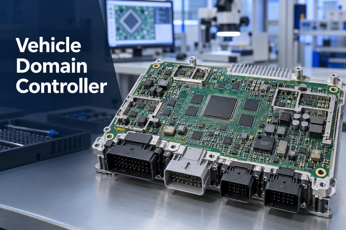
A vehicle domain controller combines the processing, communication, and control resources that were previously distributed across several automotive ECUs. Its PCBA may carry a high-performance processor, high-speed memory, vehicle-network interfaces, power-management circuits, security devices, storage, and large harness connectors on one densely populated board. Manufacturing that assembly requires more than placing components correctly; the soldering process must accommodate fine-pitch packages, uneven thermal mass, hidden joints, and strict mechanical constraints at the same time.
EBest Circuit (Best Technology) supports customer-released domain-controller projects through an IATF 16949-certified automotive quality-management system. Our capabilities include multilayer and HDI PCB fabrication, controlled-impedance manufacturing, component sourcing, mixed SMT and through-hole assembly, AOI, X-ray inspection, programming coordination, MES-based traceability, and customer-defined testing. These controls help keep the correct hardware revision, component identity, process records, and approved manufacturing route connected as a project moves from prototypes to repeat production. To discuss a domain controller PCBA build, send the released PCB data, BOM, assembly information, quantities, and required test scope to sales@bestpcbs.com.
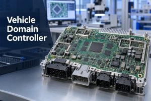
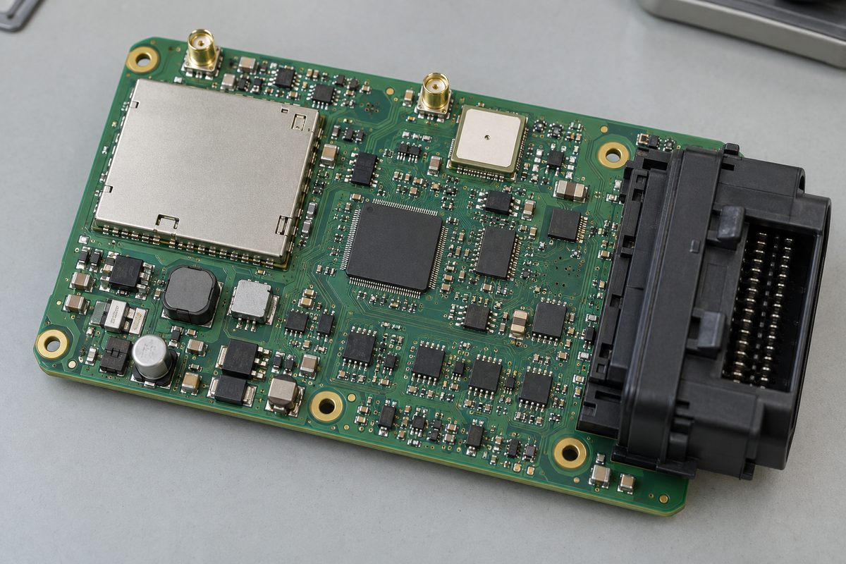
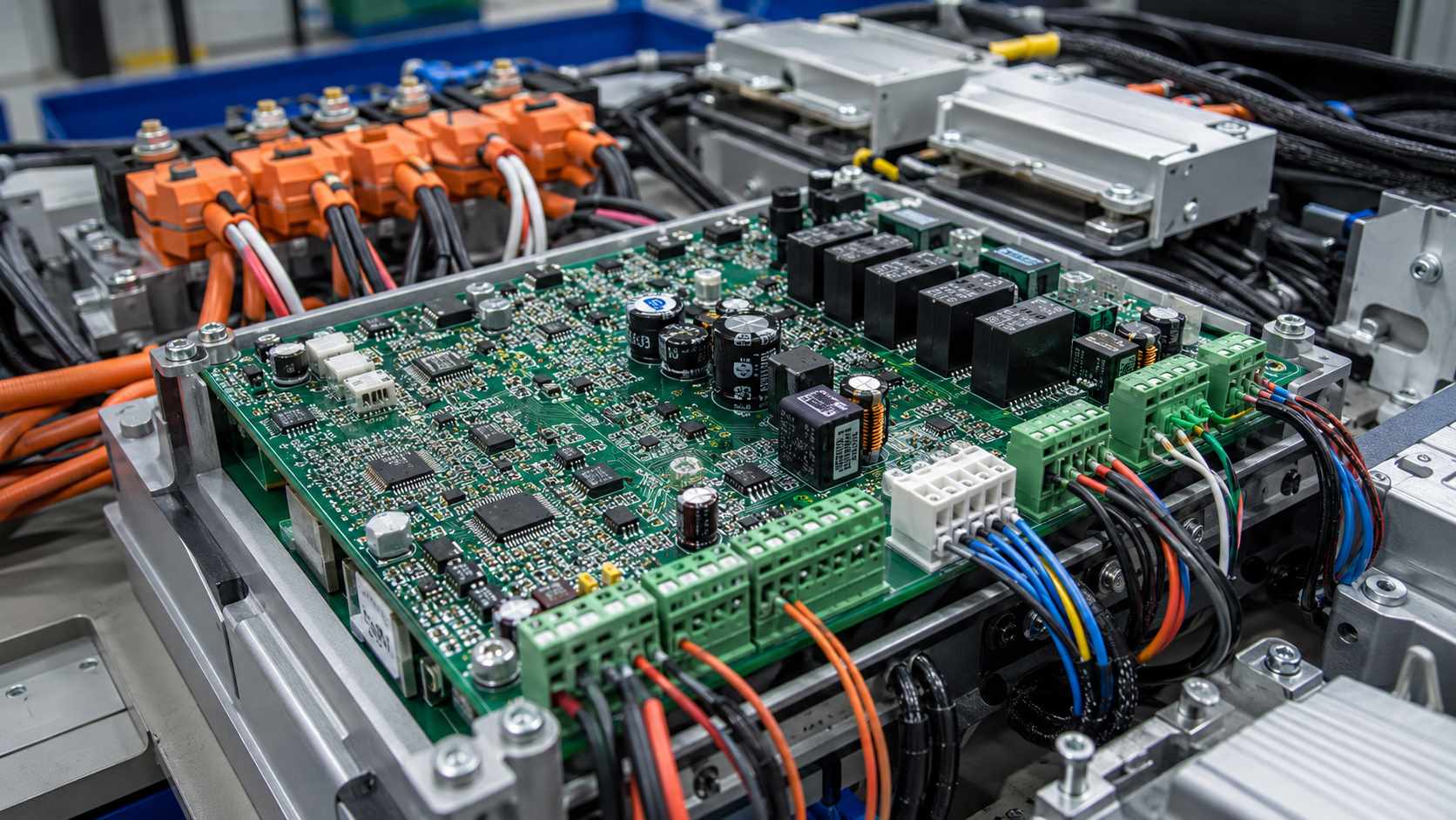
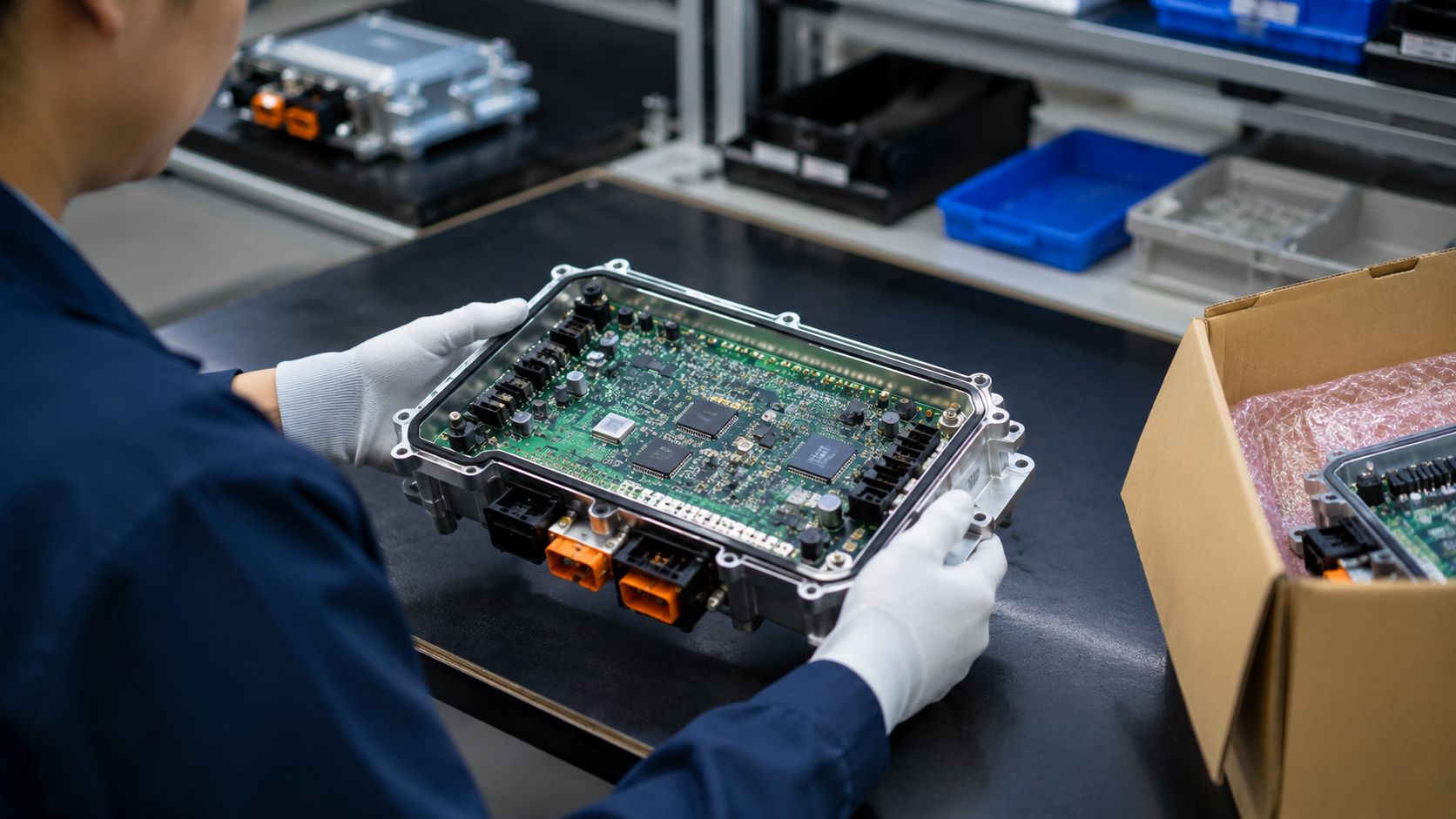
A high-density vehicle domain controller PCBA combines computing, memory, power, networking, and automotive connectors.
What Is a Vehicle Domain Controller?
A vehicle domain controller is a high-performance electronic control unit that manages several related functions within one vehicle domain. Instead of assigning every function to a separate ECU, the controller provides shared computing, communication, power-management, and software resources for a group of systems.
The “domain” describes a logical group of vehicle functions. Depending on the vehicle architecture, it may cover body and comfort systems, the digital cockpit, ADAS, propulsion, chassis, connectivity, or a combination of these areas.
A domain controller is therefore not simply a larger version of a conventional ECU. It must receive data from many sensors and network nodes, process multiple workloads, exchange information with other controllers, and maintain predictable operation when one function places a heavy demand on shared hardware.
It should also be distinguished from a zone controller. A domain controller groups functions by purpose, while a zone controller usually groups physical inputs, outputs, sensors, and actuators by their location in the vehicle. Some newer platforms use both: zone controllers collect local signals, and a domain or central computer performs higher-level processing.
How Does Automotive Domain Controller Architecture Consolidate ECUs?
Automotive domain controller architecture consolidates ECUs by moving compatible workloads onto shared processing and communication hardware. The goal is not to connect several existing ECUs inside one enclosure. It is to reduce duplicated processors, memory, power supplies, gateways, and network interfaces while coordinating the functions through a common computing platform.
For example, several cockpit functions may share an applications processor, graphics resources, memory, storage, and vehicle-network connection. An ADAS domain controller may receive camera, radar, and other sensor data through high-speed interfaces, process the information, and exchange decisions with braking, steering, or gateway controllers.
This consolidation changes the PCBA in several ways:
processor and memory density increases;
high-speed interfaces occupy more routing and connector resources;
several supply rails must start, sequence, and remain stable under changing loads;
communication traffic from CAN, CAN FD, LIN, Automotive Ethernet, or other interfaces converges on one assembly;
thermal load becomes concentrated around processors, memory, PMICs, and network devices;
a defect in one shared resource can affect several vehicle functions.
The architecture can reduce module count and wiring complexity, but it also concentrates electrical, thermal, and manufacturing risk. That is why a domain-controller PCBA cannot be treated as a generic control board with a faster processor added.
Which Functions Can an Automotive Domain Controller Combine?
An automotive domain controller combines functions that need shared computing, coordinated data, or common vehicle interfaces. The exact grouping depends on the automaker's electrical and electronic architecture; there is no universal set of functions for every controller.
Common domain groupings include:
Body domain: lighting, doors, windows, seats, mirrors, wipers, access, and comfort functions.
Cockpit domain: digital instrument clusters, infotainment, displays, audio, voice processing, and driver interaction.
ADAS domain: sensor input, image or radar processing, sensor fusion, path-related calculations, and communication with actuation controllers.
Connectivity domain: external wireless connectivity, gateways, secure data exchange, over-the-air service support, and communication between internal and external networks.
These categories can overlap. A cockpit controller may include connectivity functions, while a central vehicle computer may run workloads from more than one traditional domain. The released system architecture—not the marketing name—determines what the PCBA must support.
This distinction also keeps closely related modules separate. A body control module mainly controls body loads and convenience functions. A telematics control unit focuses on vehicle-to-network communication. A domain controller may coordinate either area, but its defining feature is the consolidation of multiple related workloads and interfaces.
What Hardware Is Inside a Vehicle Domain Control Unit?
The hardware inside a vehicle domain control unit reflects the functions it consolidates. A body-domain board may emphasize protected inputs and load drivers, while an ADAS or cockpit controller may emphasize computing performance, memory bandwidth, high-speed networking, and thermal management.
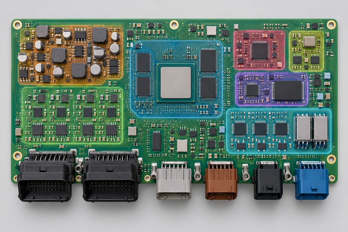
Typical hardware blocks include:
Hardware block
Typical devices
Manufacturing concern
Main processing
Automotive MCU, MPU, SoC, FPGA or accelerator
Fine-pitch BGA assembly, heat and lifecycle control
Memory
LPDDR, DDR, Flash, eMMC or UFS
Short high-speed connections and hidden solder joints
Vehicle networking
CAN, CAN FD, LIN, FlexRay and Automotive Ethernet devices
Controlled-impedance paths, termination and connector transitions
Power management
PMICs, DC-DC converters, LDOs, supervisors and protection devices
Multiple rails, switching heat and package-specific soldering
Storage and security
Secure elements, hardware security modules and nonvolatile storage
Programming, identification and configuration control
Sensor or display interfaces
SerDes, camera links, display interfaces and level translation
High-speed differential routing and connector integrity
Timing
Crystals, oscillators, clock generators and buffers
Placement sensitivity and contamination control
External connection
Board-to-board and harness connectors, coaxial or high-speed connectors
Mechanical load, coplanarity and through-hole soldering
The board may also include shielding frames, heatsink contact areas, thermal interface material, mounting points, test pads, and service or programming connectors. These mechanical features influence component placement and assembly sequence even though they are not active electronic functions.
Compared with a conventional electronic control unit board, a high-performance domain controller usually places greater pressure on routing density, package pitch, memory proximity, power distribution, and heat removal.
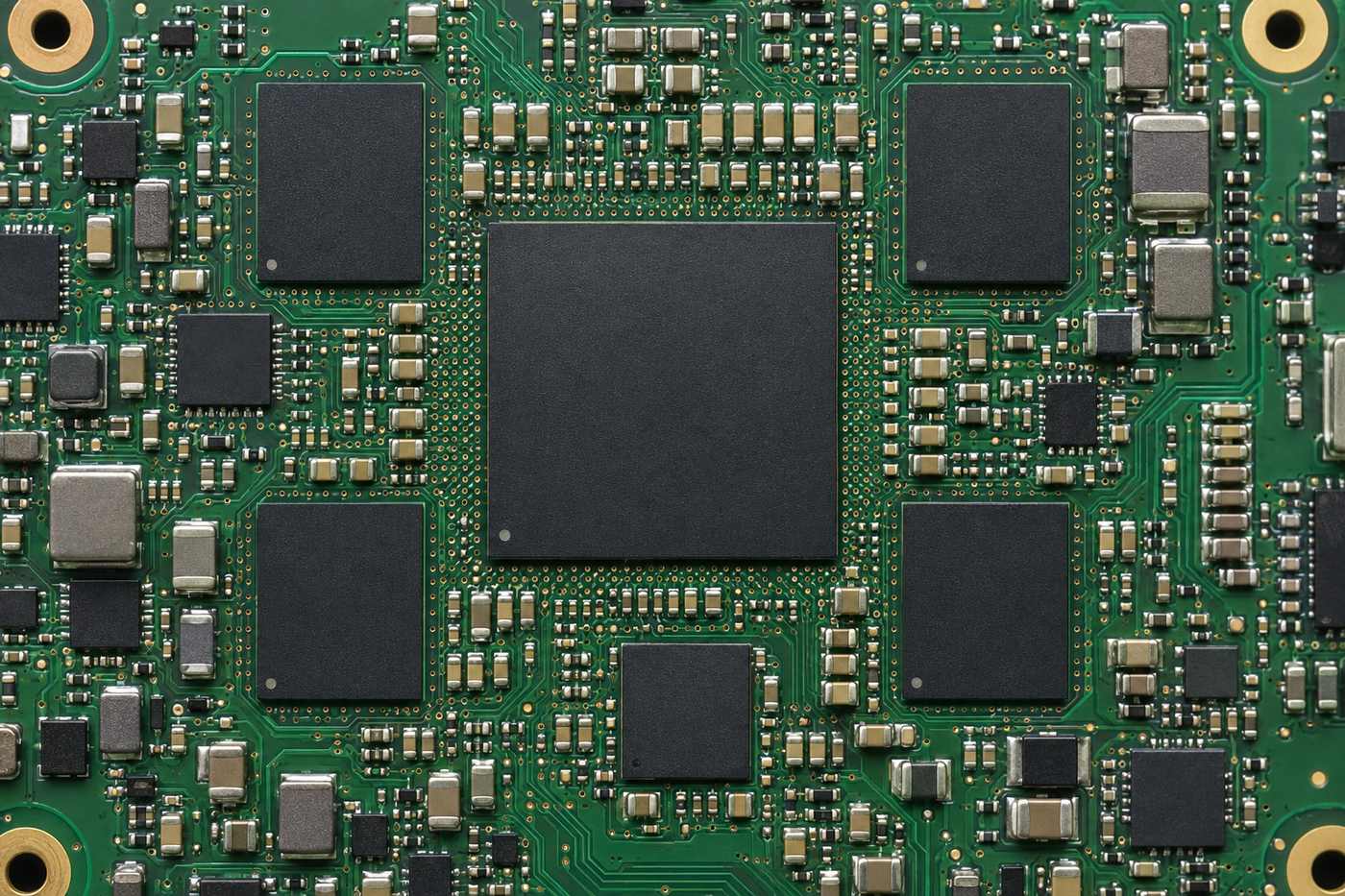
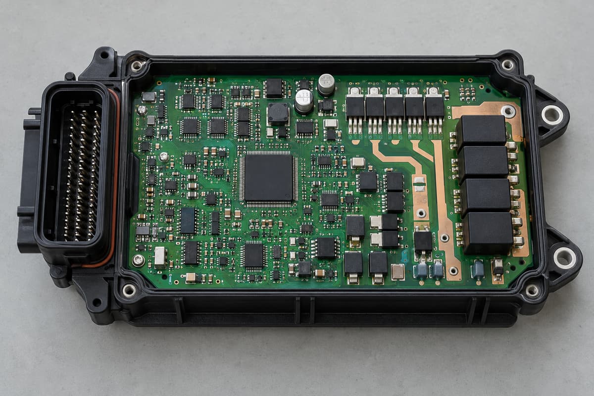
Functional hardware zones share one densely populated vehicle domain controller PCBA.
What Makes a Domain Controller PCBA Difficult to Assemble?
A domain controller PCBA is difficult to assemble because it combines components that need very different soldering conditions on the same board. A fine-pitch BGA needs controlled solder-paste deposition, board support, package alignment, and a stable reflow profile. When solder paste inspection is included in the production route, it can identify deposit-volume or alignment problems before those conditions become hidden beneath a BGA after reflow. A large connector, shield frame, inductor, or power component absorbs much more heat and may require a different assembly process.
The main difficulty is the interaction between these requirements, not any one component by itself.
Typical assembly conflicts include:
small passives and fine-pitch packages beside tall connectors or shielding structures;
high-density BGA regions with limited optical access;
large ground planes that draw heat away from selected joints;
heavy connectors that need strong solder joints without overheating nearby components;
bottom-terminated packages whose solder coverage cannot be judged by surface appearance;
components with moisture-sensitivity or storage requirements that differ from the rest of the BOM;
heatsink, shield, coating, or enclosure steps that can obstruct later inspection or rework.
Process sequencing matters. Shield frames or large connectors installed too early may block X-ray views, rework access, or test fixtures. Installed too late, they may require an additional heating process that exposes the board to more thermal stress. The assembly plan therefore has to follow the actual package mix, board construction, thermal mass, and inspection access.
That process plan also has to survive the transition from prototypes to repeat production. Recording the approved stencil, placement program, reflow profile, fixtures, inspection settings, and product revision helps prevent a later batch from being built with an outdated or incomplete process. MES-based traceability can connect those records with the applicable PCB, component lots, and programmed product identity.
Domain controllers also contain costly processors and memory devices. Soldering a visible connector correctly does not compensate for an open BGA joint beneath the main processor. Inspection and process control must therefore follow the failure modes of each package rather than rely on one final visual check.
How Are High-Pin-Count BGAs and Automotive Connectors Assembled on One PCBA?
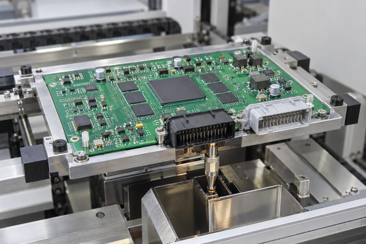
High-pin-count BGAs and automotive connectors can share one PCBA when the assembly sequence, board support, solder volumes, and thermal profile are planned for both package types. The challenge is that they sit at opposite ends of the assembly spectrum: the BGA depends on uniform hidden joints, while the connector must withstand insertion force, harness load, and repeated temperature and vibration exposure.
For the BGA area, solder-paste printing must produce repeatable deposits on adjacent fine-pitch components. Placement accuracy and package handling are important, but the reflow profile is equally critical. The board must reach sufficient temperature for complete solder formation without creating excessive package warpage, voiding, component damage, or unnecessary thermal exposure.
Large automotive connectors may use surface-mount hold-downs, press-fit pins, through-hole solder joints, or a combination of retention features. Through-hole pins can be assembled by selective soldering, pin-in-paste, or another approved process depending on connector geometry, board thickness, nearby components, and solder-side access.
Several practical interactions must be resolved:
The connector body must not shadow nearby components during reflow or block the selective-soldering nozzle.
Through-hole copper connected to large planes may need more heat than signal pins in the same connector.
Board supports must prevent the connector's mass or insertion load from flexing the BGA region.
Pin protrusion, hole fill, solder bridging, and connector seating must all remain within the released acceptance criteria.
X-ray access to the processor, memory, and other hidden joints should remain usable after the connector and shielding hardware are installed.
The best process is not automatically “reflow everything” or “solder the connector later.” It is the sequence that creates a stable window for both the hidden BGA joints and the mechanically loaded connector joints on the actual board. EBest Circuit's mixed-assembly experience allows the BGA, surface-mount hold-downs, through-hole pins, shielding hardware, and inspection access to be reviewed as one manufacturing sequence rather than as unrelated operations.
A compact fixture supports the BGA and automotive connector assembly during selective soldering.
How Do Heat and Board Warpage Affect Domain Controller Assembly?
Heat and board warpage affect domain controller assembly by changing how packages, pads, and solder joints meet during reflow. A dense processor region, thick copper planes, large connectors, and uneven component distribution can create substantial temperature differences across the PCBA. At the same time, the PCB and large packages expand at different rates.
If a BGA package or the PCB bows during reflow, corner balls may separate from their pads or touch only after part of the solder has solidified. This can create opens, head-in-pillow defects, stretched joints, or weak connections that are difficult to see from the surface. Excessive board deformation can also affect fine-pitch connectors, bottom-terminated packages, and coplanarity during later assembly steps.
Production controls should address the actual thermal and mechanical behavior:
support the panel and assembly near heavy or mechanically sensitive regions;
profile representative boards at both high-mass and low-mass locations;
keep the time and peak temperature within the limits of the PCB, packages, solder alloy, and moisture-sensitive devices;
review copper balance, board thickness, panel rails, breakaway features, and component distribution for their effect on deformation;
use package-appropriate X-ray views to assess hidden joints after soldering;
avoid fixture pressure that masks or introduces board bending during inspection and test;
control heatsink and enclosure attachment forces so that the finished board is not flexed around large BGAs.
Thermal performance in use and soldering temperature during production are related but different problems. A copper area or thermal path that helps cool the operating processor can increase local thermal mass during reflow. The assembly process must therefore be developed from the released board construction and component layout rather than from a generic oven recipe.
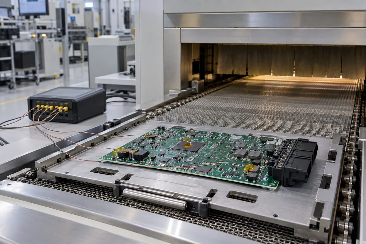
Thermocouples record representative locations before the domain controller PCBA enters the reflow oven.
FAQs About the Vehicle Domain Controller
Is a vehicle domain controller the same as an ECU?
A vehicle domain controller is a type of high-performance ECU. A conventional ECU may control one function or subsystem, while a domain controller consolidates several related functions, networks, or workloads on shared hardware.
What is the difference between a domain controller and a zone controller?
A domain controller groups functions by purpose, such as cockpit, ADAS, body, or propulsion. A zone controller groups sensors, actuators, power distribution, and network connections by physical vehicle location. A vehicle architecture may use both.
Does every vehicle domain controller use an HDI PCB?
No. HDI becomes useful when processor fan-out, memory routing, package pitch, interface count, or board-size limits cannot be handled reliably with conventional through-hole vias. The released component placement, stackup, routing density, and manufacturing limits determine whether HDI is necessary.
Why are BGAs common in domain controller PCBAs?
High-performance processors, memory, FPGAs, and network devices need many power, ground, and signal connections in a compact area. BGA packages provide high connection density and short electrical paths, but their joints are hidden and require a controlled assembly and inspection process.
Can a PCBA manufacturer build the complete vehicle domain controller?
A PCBA manufacturer can fabricate the released PCB, source approved components, assemble the board, inspect hidden and visible joints, program devices, and perform agreed electrical or functional tests. The exact deliverable depends on the released product data and quotation scope.
A reliable vehicle domain controller PCBA depends on managing several difficult features together: dense processors and memory, controlled-impedance networks, multiple power rails, heavy automotive connectors, hidden solder joints, and concentrated heat. EBest Circuit combines IATF 16949 process control with multilayer and HDI fabrication, mixed assembly, AOI, X-ray inspection, MES-based traceability, programming coordination, and customer-defined testing. When required by the confirmed project scope, automotive documentation such as PPAP-related records can also be coordinated without confusing manufacturing evidence with vehicle-level validation.
For a vehicle domain controller program, this combination helps preserve the approved product revision and manufacturing process as the build moves from prototypes to repeat production. Send your released PCB data, BOM, assembly information, quantities, and required test scope to sales@bestpcbs.com for review.
ADAS ECU hardware must process camera, radar, and vehicle-network data without allowing dense routing, power noise, hidden solder joints, or uncontrolled revisions to weaken the main board. For buyers, the practical challenge is not simply finding a factory that can produce a multilayer PCB. It is making sure the PCB structure, component package plan, assembly process, inspection method, and production files work together.
EBest Circuit (Best Technology) supports PCB fabrication, component sourcing, PCBA, inspection, and customer-defined testing for complex automotive electronics. Send your stackup requirements, Gerber files, BOM, placement data, and test instructions to sales@bestpcbs.com for a manufacturability review of your ADAS computing board.
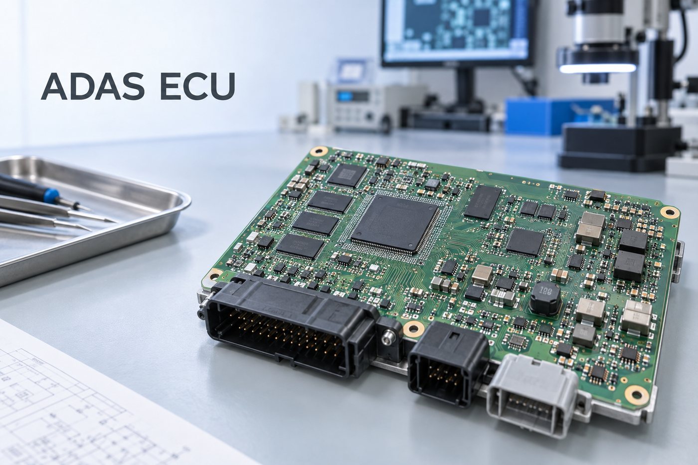
High-density ADAS ECU computing main board prepared for PCB and PCBA manufacturing.
How Is an ADAS ECU Different from Its PCB and PCBA?
An ADAS ECU is the complete electronic control unit used to support advanced driver-assistance functions. Unlike a general electronic control unit board, it is specifically built around the sensing, computing, and communication demands of driver-assistance functions. Depending on the vehicle architecture, it may receive data from cameras, radar sensors, ultrasonic sensors, inertial sensors, or other vehicle controllers. It then runs perception, decision, or sensor-fusion software and exchanges commands or status information with other vehicle systems.
The PCB and PCBA are only parts of that complete controller:
ADAS ECU: The complete unit, which may include the PCBA, firmware, application software, connectors, enclosure, shielding, thermal materials, and mechanical mounting.
ADAS ECU PCB: The bare printed circuit board before components are assembled.
ADAS ECU PCBA or main board: The populated board containing the processor, memory, power circuits, communication interfaces, and supporting components.
This distinction defines the manufacturing responsibility. A PCB and PCBA supplier can review the board for fabrication and assembly, build the bare board, source specified parts, assemble the components, inspect solder joints, and perform agreed tests. Sensor-fusion algorithms, vehicle calibration, functional-safety concepts, cybersecurity, and final vehicle validation normally remain with the customer and its system-development partners.
An ADAS domain controller is a more centralized form of automotive controller. It may consolidate work previously divided among several function-specific ECUs and process more sensor channels on one computing platform. That consolidation can increase processor pin count, memory bandwidth, interface density, power demand, and PCB routing pressure, but it does not change the boundary between the complete controller and the PCBA inside it.
What Components Are Assembled on an ADAS ECU Main Board?
The ADAS ECU architecture on the main board is usually built around a high-performance processor or system-on-chip. The precise component set depends on the number and type of sensor inputs, the software workload, and the vehicle network architecture. A typical board may include:
A main SoC, processor, MCU, GPU, or dedicated acceleration device
LPDDR4 or LPDDR5 memory close to the processor
eMMC, UFS, NOR flash, or other nonvolatile storage
PMICs, DC-DC converters, load switches, supervisors, and protection devices
MIPI CSI-2, serializer/deserializer, PCIe, Ethernet, CAN or CAN FD, SDIO, SPI, and I2C interfaces
Oscillators, clock buffers, filters, ESD protection, and common-mode components
Board-to-board, automotive data, power, and service connectors
These parts do not create equal manufacturing difficulty. A large BGA processor and nearby LPDDR devices control fanout and layer planning. Camera and high-speed network channels create impedance and return-path requirements. PMICs and processor rails require low-inductance power delivery. Connectors and protection devices influence component clearance, mechanical support, and EMC behavior.
For the buyer, the useful question is therefore not “How many components are on the board?” It is “Which packages, interfaces, and power rails control the PCB structure and assembly process?” Identifying those controlling features early prevents an apparently complete layout from reaching fabrication with an impractical via structure, incomplete impedance definition, or insufficient inspection access.
When Does an ADAS ECU PCB Require HDI or Additional Layers?
An ADAS ECU PCB does not automatically require HDI. HDI becomes justified when conventional through-hole fanout and the available layer count cannot route the required signals while maintaining reference planes, power distribution, spacing, and manufacturable feature sizes.
The decision is usually driven by five conditions:
BGA pitch and escape density. Fine-pitch processor or memory packages may leave too little room for conventional vias between pads.
Number of high-speed channels. Multiple camera, memory, PCIe, or Ethernet channels need controlled routing space and continuous reference planes.
Board outline and connector locations. A restricted enclosure or fixed connector arrangement can compress routing into a small area.
Power and ground requirements. A high-current processor with several voltage rails may need additional plane area, local copper, and dedicated return paths.
EMC and isolation constraints. Sensitive high-speed circuits, switching power sections, and external interfaces may need physical separation that consumes routing area.
A higher layer count can provide more routing channels and better separation between signal and power structures, but more layers alone do not solve a poor breakout. HDI circuit boards may use laser microvias, blind vias, buried vias, or via-in-pad around fine-pitch BGAs. Each option affects cost, registration tolerance, plating, lamination cycles, inspection, and repairability.
The most economical structure is the least complex stackup that still routes the board with acceptable impedance, return paths, copper distribution, and manufacturing margins. Before release, the PCB manufacturer should review BGA pitch, finished board thickness, via aspect ratio, annular ring, microvia depth, copper weight, material selection, and the proposed lamination sequence.
How Do LPDDR4, MIPI CSI-2, and eMMC Affect the PCB Stackup?
ADAS sensor fusion can place heavy and simultaneous demands on camera inputs, working memory, and stored data. LPDDR4, MIPI CSI-2, and eMMC serve different functions on the board, but they share one basic requirement: the stackup must provide predictable routing layers and uninterrupted reference paths before detailed routing is finalized.
LPDDR4 connects the processor to working memory through a wide, timing-sensitive bus. Memory placement, breakout geometry, reference-plane continuity, via count, and routing length must be planned as one system. Manufacturing cannot correct a topology or timing problem after the Gerber files are released, but the fabricator can verify that the selected trace widths, spacings, dielectric thicknesses, and via structures can be produced consistently.
MIPI CSI-2 commonly carries camera data into the processing platform, sometimes through serializer/deserializer devices rather than a direct camera-to-processor connection. Differential-pair impedance, intra-pair geometry, transitions, stubs, and the return path through connector regions all matter. A nominal impedance value is not sufficient if the fabrication drawing does not identify the controlled structures and their tolerances.
eMMC combines storage, command, and clock connections in a compact package. Although its routing burden may be smaller than a wide LPDDR interface, package breakout, clock quality, power integrity, and proximity to the processor can still affect placement and layer use. SDIO and other synchronous interfaces create similar concerns when clock rate and routing length increase.
The customer should release an impedance table together with the stackup and identify the nets that use each structure. The manufacturer can then calculate manufacturable trace geometries using the selected laminate and copper thickness, return the proposed stackup for approval, and use impedance coupons or agreed test methods to confirm the finished board.
How Should BGA Fanout and Vias Be Planned Around the Processor and Memory?
BGA fanout should be planned from the package pitch inward, not selected after routing becomes congested. The first review should compare pad diameter, solder-mask strategy, escape-channel width, finished hole size, annular ring, and the number of I/O rows that must reach internal layers.
For a package that allows through-hole escape, conventional vias may provide the lowest-cost and most repairable solution. As pitch decreases or the number of inner rows increases, through-holes can occupy too much routing area. Laser microvias or via-in-pad structures can open additional escape channels, but they add process controls. Filled and capped via-in-pad features must meet flatness and plating requirements so that solder does not drain into the via or leave an uneven BGA land.
Memory placement also affects fanout. Short processor-to-LPDDR connections may compete with power decoupling, eMMC routing, and processor power escapes. Moving the memory slightly can sometimes remove an HDI bottleneck; in other designs, the enclosure, thermal solution, or timing budget prevents that change. This is why the package drawing, placement, stackup, and routing constraints should be reviewed together.
Fabrication data should clearly identify blind-via spans, buried-via spans, filled vias, capped vias, back drilling if used, and any special acceptance criteria. Ambiguous via notes can cause quotation errors or, more seriously, a board built with a structure different from the designer’s intent.
Leadless processor and memory packages create the fanout density that can drive HDI decisions.
How Is an ADAS ECU PCBA Assembled and Inspected?
Automotive PCBA assembly for an ADAS ECU requires controls that match the actual package mix. The main processor, memory, storage, PMICs, small passives, bottom-terminated components, and large automotive connectors do not necessarily share the same solder-paste or thermal needs.
Stencil apertures and paste volume should be reviewed in high-density BGA and QFN areas as well as around thermally demanding power components. Component moisture sensitivity, bake requirements, feeder setup, placement accuracy, and the reflow profile must be controlled for the specified parts and board thermal mass. Large copper areas or thick multilayer constructions can change heating behavior across the assembly.
Inspection methods must also match what can be seen:
SPI checks solder-paste deposits before components hide the pads.
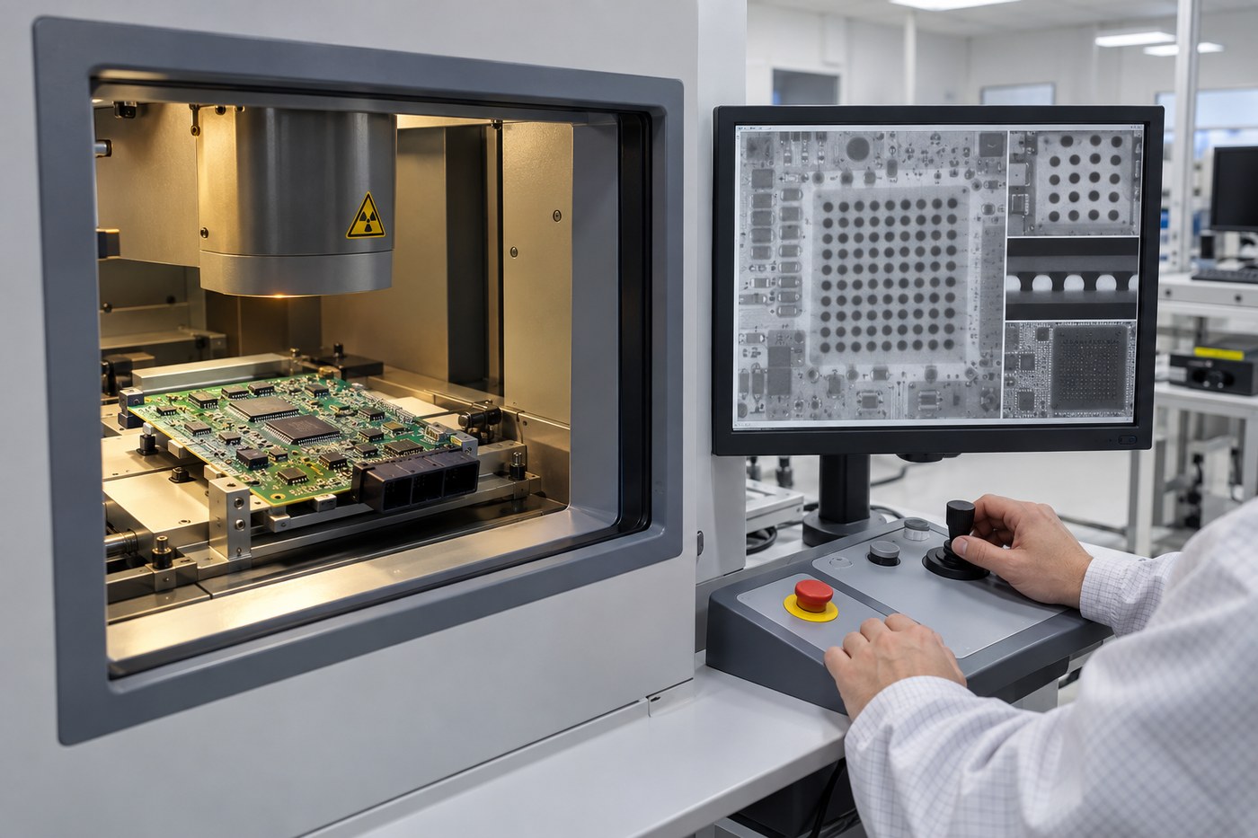
X-ray inspection evaluates hidden BGA, QFN, and via-in-pad solder regions for defects such as excessive voiding, bridging, opens, or abnormal solder distribution.
Electrical and functional tests verify the circuits and functions defined by the customer’s test coverage, fixtures, firmware, and acceptance limits.
X-ray is important, but it is not a substitute for process control or electrical testing. A visually acceptable BGA image cannot prove that every high-speed channel, memory connection, or power rail functions correctly. Buyers should therefore define which boards are X-rayed, which joints or regions are reviewed, how results are recorded, and what functional test is required after assembly.
EBest Circuit can coordinate PCB fabrication, specified component sourcing, assembly, AOI, X-ray, and agreed electrical or functional testing. The customer should supply approved firmware, test procedures, fixtures or fixture requirements, and acceptance criteria whenever programming or functional verification is included.
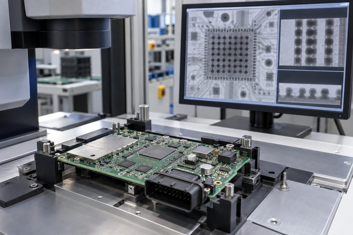
X-ray inspection reveals hidden solder-ball patterns beneath BGA packages on an ADAS ECU PCBA.
How Can an ADAS ECU Prototype Be Prepared for Repeatable PCBA Production?
A working prototype is not automatically ready for repeatable production. Repeatability starts when the approved design, materials, process assumptions, and acceptance evidence are converted into a controlled manufacturing package.
Before the next build, the customer and manufacturer should close the following items:
Freeze matching revisions of the Gerber or ODB++ data, fabrication drawing, assembly drawing, BOM, centroid file, and approved change records.
Confirm the stackup, laminate, copper weight, impedance structures, HDI build, surface finish, and any special via filling or capping.
Resolve BOM lifecycle, lead-time, package, polarity, and approved-alternative questions before purchasing.
Record stencil decisions, reflow conditions, BGA or QFN X-ray criteria, and any workmanship requirements that differ from the normal process.
Define programming files, software versions, fixture ownership, test steps, pass/fail limits, and required test records.
Preserve traceability between the board revision, BOM revision, assembly lot, component lots, and test results when the project requires it.
This preparation protects the buyer from three common production problems: building the wrong revision, accepting an unapproved component substitution, and discovering too late that the prototype test depended on an undocumented setup. It also makes quotation and scheduling more accurate because the factory can see which materials, special processes, inspections, and tests belong to the released configuration.
For a new supplier transfer, do not rely only on the previous purchase order. Provide the current controlled package and identify any deviation accepted on earlier builds. A short pre-production review can expose conflicts among the PCB drawing, BOM, placement file, assembly notes, and test instructions before material is committed.
FAQs About ADAS ECU
Is an ADAS domain controller the same as an ADAS ECU?
Not always. An ADAS ECU may perform one defined driver-assistance function, while an ADAS domain controller usually consolidates several functions or sensor channels on a more centralized computing platform. Both contain PCBAs, but a domain controller often creates higher processing, memory, interface, power, and thermal demands.
Does every ADAS ECU PCB need HDI?
No. HDI is appropriate when BGA pitch, fanout density, board size, interface count, or routing constraints cannot be handled efficiently with through-hole vias and a conventional multilayer stackup. The decision should follow a layout and manufacturability review.
How many layers should an ADAS ECU PCB use?
There is no universal number. The layer count depends on BGA escape needs, high-speed signal groups, reference planes, power rails, EMC separation, copper weight, and the available board area. The stackup should be agreed before routing is finalized.
How are hidden BGA solder joints inspected?
X-ray inspection is used to evaluate solder distribution and identify visible evidence of bridging, opens, excessive voiding, or other abnormalities beneath the package. It should be combined with SPI, AOI, process records, and appropriate electrical or functional tests.
What files are needed to quote an ADAS ECU PCB and PCBA?
Provide the Gerber or ODB++ data, fabrication drawing, stackup and impedance requirements, BOM, assembly drawing, centroid file, and any special workmanship, programming, inspection, or test instructions. Include the expected quantity and revision so the quotation reflects the intended build.
If you need a manufacturing review for an ADAS ECU PCB or high-density PCBA, send the controlled project files and expected build quantity to sales@bestpcbs.com. EBest Circuit (Best Technology) can review the fabrication, sourcing, assembly, inspection, and agreed testing scope before production.
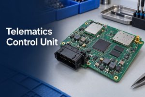
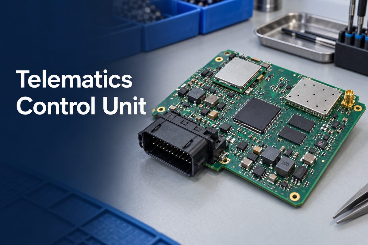
A telematics control unit connects a vehicle’s internal networks with cellular, satellite-navigation, and cloud services. It receives vehicle data, adds location or communication information, processes selected messages, and exchanges data with external platforms. That combination enables functions such as remote diagnostics, emergency calling, fleet monitoring, stolen-vehicle tracking, and over-the-air service support.
For a product team, the TCU is also a demanding electronic assembly. Wireless modules, processors, memory, vehicle-network interfaces, power protection, RF connections, and large automotive connectors must work together inside a limited enclosure. EBest Circuit can support PCB fabrication, component sourcing, PCBA assembly, manufacturing review, inspection, traceability, and customer-defined testing. To discuss a TCU board build, contact sales@bestpcbs.com with the released manufacturing data and required test scope.
What Is a Telematics Control Unit?
A telematics control unit, usually shortened to TCU, is the electronic module that provides a vehicle with a controlled connection to external communication networks. It acts as a bridge between information available inside the vehicle and services outside it. It is also called a T-Box in some automotive markets.
The complete unit is more than a circuit board. Depending on the product, it may include:
an assembled PCB;
a cellular modem and SIM or eSIM function;
a GNSS receiver;
a processor or microcontroller;
memory and secure storage;
CAN, CAN FD, LIN, or automotive Ethernet interfaces;
Wi-Fi, Bluetooth, or V2X hardware;
RF connectors or internal antennas;
protected power supplies and a backup-energy function;
firmware, security functions, an enclosure, and vehicle connectors.
The exact boundary varies by vehicle architecture. One TCU may focus on emergency calling and remote diagnostics, while another may also support Wi-Fi access, OTA communication, fleet data, infotainment services, or V2X. The released system specification—not the label “TCU” alone—determines what the hardware must contain.
This distinction also affects sourcing. A PCB supplier may fabricate the bare board, while a PCBA supplier may source components, assemble the board, program devices, and perform agreed tests. The complete telematics product still requires firmware, antennas, enclosure integration, network provisioning, security validation, and vehicle-level approval.
What Is a TCU in a Car, and What Does It Do?
A TCU collects selected vehicle information and transfers it to an external service, while also receiving authorized data or commands from outside the vehicle. It does not normally replace every other electronic control unit. Instead, it communicates with those controllers through the vehicle network.
A typical data path works like this:
Vehicle ECUs publish status, sensor, diagnostic, or event data on an internal network.
The TCU receives the permitted messages through CAN, CAN FD, LIN, or Ethernet interfaces.
Its processor filters, packages, encrypts, stores, or prioritizes the information.
A GNSS receiver can add position and time data.
The cellular modem sends the required information to a cloud or service platform.
Authorized responses, updates, or remote-service requests return through the controlled communication path.
This data flow can support several functions:
automatic crash notification and emergency calling;
remote diagnostics and fault reporting;
location, geofencing, and stolen-vehicle tracking;
fleet usage and maintenance information;
remote status checks and selected vehicle commands;
data transport for OTA software updates;
connectivity for infotainment or onboard Wi-Fi;
communication with external road or vehicle infrastructure.
Not every TCU supports every function. A commercial-vehicle fleet unit and an OEM passenger-car module may have different networks, environmental limits, security requirements, data rates, and service lives. Those differences change the component set, PCB complexity, assembly process, and validation plan.
What Components Are Inside a Telematics Module?
A telematics module normally combines a computing section, wireless communication section, vehicle interfaces, power conditioning, and protection. The components are selected as a system because a failure in one section can interrupt the complete data path.
Hardware block
Typical purpose
Manufacturing concern
Processor or MCU
Runs communication, diagnostics, security, and control tasks
Small components, placement accuracy, approved substitutions
Connector system
Links power, vehicle networks, antennas, and service ports
Coplanarity, pin soldering, mechanical support
The BOM must identify the complete manufacturer part number, package, grade, approved alternatives, and any programming or traceability requirements. A generic description such as “LTE module” or “GNSS filter” is not enough for controlled sourcing. Devices with similar commercial descriptions may differ in frequency bands, qualification status, firmware, temperature range, package revision, moisture sensitivity, or lifecycle status.
Long-lead wireless modules, processors, secure devices, automotive connectors, and memory parts deserve early supply-chain review. If an alternative part changes the footprint, RF behavior, power demand, firmware interface, or qualification status, it is an engineering change—not a routine purchasing substitution.
How Do Cellular, GNSS, and Vehicle Networks Work Together?
Cellular, GNSS, and vehicle-network circuits perform different jobs but meet at the TCU processor. Vehicle networks provide information from inside the vehicle, GNSS supplies position and timing, and cellular communication carries selected data between the vehicle and remote services.
The processor controls that exchange. It decides which vehicle messages are relevant, manages communication sessions, stores data when coverage is unavailable, and sends queued information after the connection returns. It may also coordinate Wi-Fi, Bluetooth, or V2X hardware when those functions are part of the product.
These interfaces create several hardware interactions:
a cellular transmitter can generate noise that reduces GNSS receiver sensitivity;
digital clocks and high-speed memory can couple noise into RF circuits;
vehicle-network transients can enter through harness connections;
modem transmit bursts can create rapid changes in power demand;
enclosure, cable, shielding, and antenna placement can alter RF performance;
sleep and wake behavior can affect both current consumption and network availability.
The PCBA must therefore preserve the separation and reference structures defined by the released design. During manufacturing review, the supplier can check whether the stackup, impedance requirements, fabrication notes, component footprints, assembly clearances, shield features, and test points are producible. The product owner remains responsible for proving antenna performance, protocol behavior, wireless certification, security, and operation in the intended vehicle.
What Makes an Automotive Telematics Control Unit Difficult to Assemble?
An automotive telematics control unit is difficult to assemble because its PCBA combines dense digital electronics, RF circuits, vehicle power, large connectors, and hidden solder joints. A process that works for a simple controller may not provide enough control for this mixture.
Depending on the released design, a TCU may combine RF sections, high-speed digital interfaces, controlled-impedance routing, and multilayer PCB stackup requirements on the same assembly.
Important production challenges include:
Mixed component geometry: The same board may contain small RF passives, BGAs, QFNs, modules, shields, and large through-hole connectors. Stencil design and reflow settings must support different solder-volume and thermal demands.
Hidden solder joints: Modems, processors, memory, and power packages may use BGA, LGA, QFN, or bottom-terminated packages. AOI cannot see every critical joint, so the inspection plan may require X-ray.
Module coplanarity: A wireless module with many edge or underside pads can produce opens or uneven soldering if paste deposition, placement pressure, warpage, or reflow is poorly controlled.
RF component sensitivity: Matching components are often small and value-specific. A wrong value, rotated device, tombstone, or unauthorized alternative can change performance even when the board powers on.
Shield and connector assembly: Shield frames, coaxial connectors, and vehicle connectors can introduce thermal imbalance, mechanical stress, or secondary soldering operations.
Vehicle power conditions: Protection and power components may carry higher current or dissipate more heat than the digital section. Their joints, copper connections, and thermal interfaces need suitable process control.
Programming and identity: The assembly may require boot code, secure provisioning, serial numbers, MAC addresses, or customer-specific labels. The exact responsibility and data-handling method must be agreed before production.
Manufacturing review should happen before material release. Conflicts among the Gerber or ODB++ data, BOM, pick-and-place file, assembly drawing, programming instruction, and test specification can otherwise reach the line as different interpretations of the same product revision.
Which Assembly Defects Should TCU Manufacturing Testing Detect?
TCU manufacturing testing must detect more than a board that is completely dead. An assembly defect can produce intermittent communication, weak RF performance, unexpected resets, high standby current, unreliable vehicle-network data, or failures that appear only after temperature or vibration changes.
Common defect paths include:
insufficient solder or opens beneath BGA, LGA, QFN, and module pads;
solder voiding beneath power or thermal pads;
bridges around fine-pitch processors, transceivers, and connectors;
missing, wrong-value, shifted, or tombstoned RF passives;
poor wetting on shield frames or large ground connections;
damaged coaxial or board-to-board connectors;
excessive residue or contamination near high-impedance and RF sections;
cracked joints caused by connector insertion or board handling;
incorrect component revision or an unapproved BOM substitute;
incomplete programming, duplicated identifiers, or mismatched firmware files.
No single inspection method finds all of these problems. SPI can verify solder-paste deposition before placement. AOI can identify visible polarity, placement, and solder defects. X-ray can examine concealed joints and voiding. Electrical tests can detect opens, shorts, supply problems, and selected component values. A functional fixture can exercise defined power, communication, and I/O behavior.
The acceptance plan should connect each important risk with an appropriate check. For example, an AOI record cannot prove cellular sensitivity, and a successful network connection cannot prove that every hidden solder joint has acceptable process quality. Inspection evidence and system-performance evidence answer different questions.
How Do You Choose a PCBA Manufacturer for a Telematics Unit?
Choose a PCBA manufacturer whose experience covers the difficult parts of the TCU assembly, not only general SMT production. EBest Circuit has experience with the component, process, inspection, and traceability controls that these mixed RF and automotive electronics projects require.
checking BOM data and complete manufacturer part numbers before purchasing;
controlling component alternatives and obtaining customer engineering approval before release;
managing moisture-sensitive devices and baking requirements where applicable;
using SPI, AOI, X-ray, electrical testing, and agreed functional testing for different acceptance needs;
supporting programming, serialization, labeling, and production-data traceability;
completing first-article inspection before volume release;
maintaining board, production-lot, revision, and critical-component traceability;
working with customer fixtures, test limits, software, and golden samples;
separating PCBA manufacturing acceptance from antenna, wireless-network, firmware, cybersecurity, and vehicle-level validation.
These controls help prevent a TCU project from being released only because the assembly looks complete. Depending on the agreed scope, production evidence can include first-article results, AOI or X-ray records for defined features, programming logs, serial-number records, electrical-test results, functional-test reports, and approved nonconformance records.
EBest Circuit can review the released PCB and assembly package, identify manufacturing conflicts, source specified components, assemble the mixed-technology PCBA, and coordinate the inspection and customer-defined testing included in the quotation. Broader automotive PCB assembly controls may also apply, while each TCU project should still define its critical components, inspection points, test limits, and required records.
FAQs About the Telematics Control Unit
Is a telematics control unit the same as an ECU?
A TCU is a type of automotive electronic control unit focused on external connectivity and telematics functions. “ECU” is the broader term for vehicle controllers. An electronic control unit board may support engine, body, chassis, battery, gateway, or other functions, while a TCU specifically manages vehicle-to-network communication and related services.
Is a TCU the same as a transmission control unit?
No. Both may use the abbreviation TCU. In this article, TCU means telematics control unit. A transmission control unit manages transmission operation and is a different automotive controller.
Does every telematics control unit include 5G?
No. The wireless technology depends on product generation, target region, service requirements, network availability, cost, and lifecycle plan. A TCU may use LTE, 4G, 5G, satellite communication, or another approved connection. The exact modem and supported bands must be defined in the product specification and BOM.
Can AOI prove that a TCU PCBA will communicate correctly?
No. AOI checks visible assembly characteristics such as component presence, position, polarity, and selected solder features. Communication performance requires suitable electrical, programming, RF, network, and system-level tests. X-ray may also be required for concealed solder joints.
What testing can a PCBA manufacturer perform for a TCU?
The available scope may include SPI, AOI, X-ray, electrical testing, programming, interface checks, and customer-defined functional testing. Antenna performance, cellular certification, GNSS performance, cybersecurity, cloud communication, vehicle integration, and regulatory approval normally require additional product- or system-level validation defined by the customer.
If you need PCB fabrication or PCBA support for a telematics control unit, send the released board data, BOM, component-placement file, drawings, programming instructions, test requirements, quantity, and required production records to sales@bestpcbs.com for review.
BCM most often means Body Control Module in an automotive context. It is an electronic control unit that reads switches, sensors, and vehicle-network messages, runs body-control logic, and drives loads such as lamps, door locks, windows, mirrors, wipers, and interior convenience systems.
A BCM is not just a processor board. Its PCB must place low-voltage logic, vehicle communications, protected power inputs, and higher-current load drivers in one compact assembly while handling electrical transients, heat, electromagnetic interference, vibration, and long service life. This guide opens the module and follows the signal path from an input to a physical vehicle function.
What Is a BCM on a Car?
A BCM on a car is the electronic control unit responsible for body and convenience functions rather than combustion, traction, or transmission control. The exact boundary varies by vehicle: one platform may use a central BCM, while another divides the same work among front, rear, door, or zone controllers.
The search phrase what is a bcm module usually refers to the same device. “Module” describes the complete unit: the populated PCB, connector interface, housing, firmware, and calibration data. Replacing only the circuit board may not restore operation if the vehicle also requires coding, key matching, or configuration.
Module
Primary responsibility
Typical inputs and outputs
BCM
Body, access, lighting, and cabin convenience functions
Door switches, locks, lamps, windows, mirrors, wipers, network messages
Powertrain control; on some vehicles it combines engine and transmission control
Engine and transmission sensors, injectors, ignition, shift control
BCM, ECM, and PCM names are not perfectly standardized across automakers. The vehicle service information and electrical architecture remain the authority for a specific model.
What Does a BCM Control in a Car?
A BCM commonly controls exterior and interior lights, central locking, power windows, mirrors, wipers, washers, retained accessory power, and selected heaters or motors. It also coordinates these functions with door modules, gateways, and other ECUs when the vehicle architecture distributes the load control.
Access: central locking, keyless-entry requests, trunk or tailgate release, and anti-theft status exchange.
Doors and glass: window motors, mirror fold or heating, door-ajar inputs, and child-lock functions.
Wipers and washers: stalk requests, intermittent timing, rain-sensor messages, and pump or motor control.
Cabin functions: interior lamps, retained accessory power, seat or steering-wheel heaters, and wake/sleep coordination.
Not every vehicle assigns every function to the BCM. Some loads are driven by door or zone modules after receiving BCM commands over CAN or LIN; the model-specific wiring diagram identifies the responsible controller and output stage.
How Does a BCM Work?
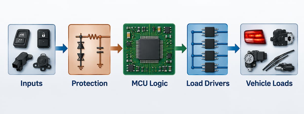
A BCM works through five blocks: it receives an input, protects and conditions the signal, evaluates the request in a microcontroller, commands a driver, and monitors the resulting load. For example, a door-switch transition can be debounced by the input circuit, interpreted by firmware, transmitted to another ECU if required, and used to switch a courtesy lamp through a protected high-side output.
The complete path normally includes:
Input acquisition: switches, Hall sensors, analog sensors, and messages from CAN or LIN nodes.
Protection and conditioning: filtering, voltage clamping, reverse-polarity protection, level shifting, and transient-tolerant interfaces.
Decision logic: an MCU applies timing, state-machine, safety, diagnostic, and energy-management rules.
Load actuation: smart high-side switches, low-side drivers, half bridges, full bridges, or relays operate lamps, heaters, solenoids, and motors.
Feedback: current sense, fault flags, temperature status, position signals, and bus messages confirm whether the command succeeded.
Sleep behavior is another core function. When the vehicle is parked, the BCM must reduce its own current and coordinate network sleep without missing legitimate wake events such as a key request or door opening.
What Is Inside a BCM Module?
Inside a BCM module are a microcontroller, regulated power rails, CAN or LIN transceivers, protected input circuits, load drivers, nonvolatile memory, clocks, connectors, and thermal paths. Exact parts depend on the vehicle architecture, but real automotive reference designs make the functional split concrete.
Circuit function
Representative automotive device
Role in a BCM-class design
Microcontroller
TI AM263P4-Q1
Runs control logic, diagnostics, timing, and network software in a recent zone-controller reference design
Power-management IC
TI TPS65386x-Q1 family
Generates and supervises regulated rails for the processor and peripheral circuits
CAN/CAN FD transceiver
TI TCAN1043A-Q1
Converts MCU logic-level data to the differential vehicle bus and supports wake/sleep behavior
LIN transceiver
TI TLIN1021A-Q1
Connects lower-cost local nodes such as switches, small actuators, or door electronics
Smart high-side switch
TI TPS1HC30-Q1
Switches a protected body load and provides diagnostic feedback
Motor driver
TI DRV8245S-Q1
Controls bidirectional DC loads such as selected window, latch, or seat mechanisms
These are examples, not a universal BCM bill of materials. A more integrated approach is also possible: Infineon’s TLE9560-3QX system basis chip combines a 5 V regulator, CAN FD and LIN communication, two half-bridge drivers, high-side outputs, and SPI control in one device. The final choice depends on current, channel count, diagnostic coverage, thermal limits, software architecture, and the automaker’s component requirements.
How Does a BCM Communicate With Other ECUs?
A BCM communicates with other ECUs through vehicle networks, most commonly CAN or CAN FD for coordinated control and LIN for lower-cost local devices. Some newer centralized or zonal architectures also use automotive Ethernet for higher-bandwidth links, but not every BCM includes every interface.
CAN: robust multi-node communication for status, commands, diagnostics, and coordination among body, gateway, powertrain, and instrument modules.
CAN FD: retains CAN arbitration while allowing a larger payload and faster data phase when the network and transceivers support it.
LIN: a lower-cost single-master network suited to local switches, small motors, lighting nodes, and door electronics.
Automotive Ethernet: a higher-bandwidth link increasingly associated with gateways and zone controllers rather than a universal requirement for conventional BCMs.
The PCB must keep these communication paths away from noisy switching nodes, preserve their return paths, and implement the termination, common-mode filtering, ESD protection, and connector pinout required by the actual interface design.
What Makes a BCM PCB Different From a General Control Board?
A BCM PCB differs from a general control board because it combines battery-connected power, sensitive digital logic, network interfaces, and multiple switched loads in a harsh electrical and mechanical environment. A circuit that works on a bench can still fail in a vehicle if the layout cannot handle a load dump, inductive switching, reverse battery, ground offset, thermal cycling, or conducted and radiated noise.
Power partitioning: battery inputs, regulators, high-current outputs, logic rails, and communication grounds require a deliberate placement and return-path strategy.
Current and heat: copper width, copper weight, via arrays, thermal spreading, connector pins, and driver packages must be checked against actual current and ambient temperature.
Transient protection: suppressors, filters, reverse-polarity circuits, and protected drivers must be placed so surge current does not flow through the logic-ground path.
EMC control: fast driver edges, motor currents, and DC/DC converters must not corrupt CAN, LIN, crystal, reset, or sensor signals.
Mechanical reliability: connector insertion force, mounting points, enclosure support, vibration, moisture exposure, and coating keep-outs affect the PCB layout and assembly process.
Standard FR-4 PCB manufacturing may suit many body-control designs, but “FR-4” alone does not define a finished material system. The laminate grade, glass-transition temperature, CAF performance, copper construction, solder mask, coating, and validation plan should be matched to the specified environment rather than chosen from a generic layer-count rule.
Which PCB and PCBA Checks Matter for BCM Hardware?
The most important checks are power-path verification, network-layout review, assembly inspection, programming control, and functional testing under representative loads. They should be agreed before the design is released because a fixture, connector breakout, firmware image, or diagnostic interface may affect both PCB layout and production cost.
PCB review: confirm stackup, copper weight, high-current trace temperature rise, thermal vias, creepage and clearance, test-point access, connector support, and coating keep-outs.
Signal-integrity and EMC review: examine CAN/CAN FD differential routing, LIN protection, clock and reset nets, switching loops, power-plane discontinuities, and return-current paths.
Assembly controls: use solder paste inspection where applicable, AOI for visible joints, and X-ray for hidden-pad packages or thermal-pad voiding when required by the design.
Programming and traceability: control firmware version, calibration data, serial or lot records, approved component alternatives, and the relationship between each assembly and its test result.
Functional testing: exercise wake/sleep behavior, CAN and LIN communication, input thresholds, load outputs, current sensing, fault reporting, and quiescent current with defined limits.
A capable PCB assembly process should connect inspection records to the released BOM, placement data, firmware, and test procedure. Our quality and inspection overview explains the broader controls available for PCB and PCBA projects; the exact automotive test matrix still needs to be defined by the customer’s product requirements.
FAQ About BCM Hardware
Is a BCM the same as an ECU?
A BCM is one type of ECU. “ECU” is the broad category for electronic control units; “BCM” identifies the unit assigned to body and convenience functions.
Can one car have more than one BCM?
Yes. A vehicle can distribute body functions across a central BCM, door modules, a smart junction box, gateway, or front and rear zone controllers. The physical module count depends on the electrical architecture.
Does every BCM use CAN and LIN?
No. CAN is common, and LIN is widely used for local low-cost nodes, but the actual mix can include CAN FD, Ethernet, direct hardwired inputs, or proprietary interfaces.
Can a BCM switch loads without mechanical relays?
Yes. Smart high-side or low-side semiconductor switches can replace some relays and add current sensing, short-circuit protection, and diagnostic feedback. Relays may remain where load, isolation, cost, or fail-safe requirements favor them.
Why does a BCM need low sleep current?
The BCM remains connected to the vehicle battery while parked. Excess quiescent current can discharge the battery, so the design must place the MCU, transceivers, regulators, and output drivers into defined low-power states while preserving valid wake sources.
Where can I find BCM failure and reset information?
For symptoms, test methods, common failure causes, reset considerations, and repair-oriented questions, read our separate guide to Body Control Module testing and failure symptoms. Keeping that troubleshooting topic separate avoids mixing service procedures with this hardware-architecture guide.
How Can We Support Your BCM PCB and PCBA Project?
We can manufacture and assemble customer-released BCM and automotive control-board designs, with engineering review focused on manufacturability, stackup, materials, component availability, assembly, inspection, and test preparation. At EBest Circuit, our listed quality certifications include ISO 9001:2015 and IATF 16949; we confirm the applicable facility, process scope, and project requirements before quotation.
Our support can combine PCB fabrication, component sourcing, SMT and through-hole assembly, AOI, X-ray inspection where applicable, and functional-test coordination. Send your Gerber files, BOM, pick-and-place data, stackup or copper requirements, quantities, coating specification, firmware instructions, and test limits to sales@bestpcbs.com. We will review the package against the required automotive environment instead of treating it as a generic control board.
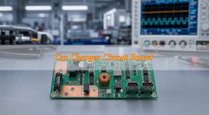
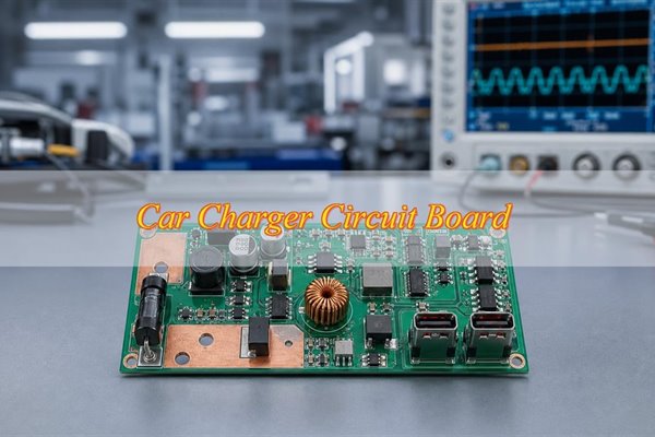
A car charger circuit board converts vehicle power into a stable USB output while protecting the connected device and managing charging behavior. The car charger circuit board combines an input protection stage, a DC-DC power stage, a charging or USB controller, filtering and the output connector in a compact space. This article covers low-voltage automotive USB charging modules used in plug-in, dashboard and center-console products, not EV traction-battery or onboard chargers.
The practical challenge is not simply making the USB port turn on. An automotive USB charger PCB must carry the required current without excessive voltage drop, remove heat from the switching components, survive the specified electrical environment and keep the connector mechanically stable. If your design files are ready, send the Gerber or ODB++, BOM, schematic, mechanical data and test requirements to sales@bestpcbs.com for a free DFM review.
What Is a Car Charger Circuit Board and How Does It Work?
A car charger PCB is a compact power-conversion assembly that turns the vehicle supply into the voltage and charging behavior required at one or more USB ports. Power normally enters through the module connector, passes through protection and filtering, reaches the switching converter, and then flows through the charging controller or port controller to the USB output.
Input protection: Limits damage from reverse connection, overvoltage, transient events or a short that the product specification requires the module to withstand.
DC-DC conversion: Regulates the varying vehicle input to the output needed by the selected charging architecture.
Charging control: Identifies or negotiates the permitted output behavior for USB-A, USB-C or USB Power Delivery.
Filtering and grounding: Contain switching noise and give the power and control circuits a stable reference.
Connector and enclosure path: Carry current to the cable, support insertion forces and help move heat away from the board.
These blocks work as one system. A capable controller cannot compensate for an undersized current path, and a large copper area will not solve a poor thermal connection beneath the power package. The design should therefore be reviewed from the vehicle input to the USB contact rather than as isolated components.
What Types of Car Charger PCBs Are Used for USB-A, USB-C and USB PD Modules?
The port type sets only part of the design; output behavior, available power, port count and mechanical format determine the actual circuit and assembly. Common USB car charger PCB variants include USB-A, USB-C, USB PD and multi-port boards. Two products can use the same connector while requiring different controllers, power stages, firmware and validation.
USB-A charging boards: Commonly combine a regulated power stage with a charging-port controller and a mechanically supported receptacle. The layout must protect output voltage from cable and connector losses, while the assembly drawing defines connector position, shell tabs and orientation.
USB-C charging boards: Add configuration and attachment-detection requirements. The smaller connector geometry and inaccessible joints may also change stencil design, inspection access and the method used to verify connector alignment.
USB PD charging boards: Require a compatible power stage, PD controller and approved configuration for the profiles the product is intended to provide. USB-IF maintains the current USB Power Delivery specification; hardware, controller configuration and functional testing should refer to the same approved product requirement.
Multi-port charging boards: Add power sharing, simultaneous-load behavior, denser connector placement and concentrated heat. Evaluate a dual-port board under the intended combined load rather than testing each port separately and assuming the same result.
What Electrical and Protection Requirements Affect a Car Charger Circuit Board?
The protection circuit must be selected from the customer’s defined input conditions and failure tests, not from a generic “automotive” label. Vehicle supply conditions vary by product and system. The RFQ should state the normal input range, abnormal-input conditions, transient requirements and recovery behavior that the finished module must meet.
Reverse-polarity protection: Confirm how the circuit blocks or tolerates an incorrect supply connection and whether the selected device creates a significant voltage or thermal penalty.
Overvoltage and transient protection: Coordinate the suppressor, switch and converter ratings so the first protection device does not merely pass excessive stress to the next part.
Overcurrent and short-circuit behavior: Define the trip, limiting and recovery response at both the input and the USB output where applicable.
Input and output filtering: Place the filter around the actual noisy current path and verify it with the target wiring, load and enclosure conditions.
Connector-side protection: Review ESD and unintended voltage exposure at the user-accessible port as part of the product requirement.
The protection parts also influence placement and heat. For example, putting a suppressor close to the input connector can shorten its discharge path, but the surrounding copper, clearances and nearby heat-sensitive components still need to suit the specified stress. The right outcome is a coordinated protection path, not the maximum part rating in every position.
How Should the Power Layout Be Designed for a Car Charger PCB?
A reliable layout keeps the high-current path wide and continuous while making the switching loop physically small. The two goals are related but not identical. Current capacity depends on the complete conductor path; switching behavior depends heavily on loop area, component placement and the return path.
Follow the power path: Review the route from input connector to protection device, converter, inductor, output capacitor and USB connector. Pad exits, thermal reliefs, via transitions and connector contacts can be more restrictive than the main trace.
Minimize the switching loop: Place the switching device, inductor and high-frequency capacitors according to the controller manufacturer’s layout guidance. Keep sensitive feedback and configuration signals away from noisy nodes.
Provide a deliberate return path: Avoid splitting the reference beneath critical control or high-frequency paths. Ground vias should support the intended current and thermal flow rather than being added without a clear function.
Avoid copper neck-downs: Check changes in width at pads, fuses, shunts, vias and connector pins. Local loss and heat often appear where the conductor becomes narrow for only a short distance.
Plan test access: Add stable measurement points for the input, regulated output, port output and key control nodes without disturbing the power loop.
During DFM, the layout should be checked against the finished copper, drill and assembly constraints that will actually be produced. A visually broad polygon is not proof of current capacity if its connection to a pad passes through a narrow spoke or an insufficient via group.
How Should Heat Be Managed in a Compact Car Charger PCB?
Thermal control starts by identifying where loss occurs and where that heat can leave the assembled module. The converter, MOSFETs, inductor, protection devices and connector contacts can all become limiting points. Their temperatures depend on conversion loss, conductor resistance, airflow, enclosure contact and how nearby heat sources interact.
Copper spreading: Connect useful copper to the thermal pad or power node without enlarging the noisy switching node unnecessarily.
Thermal vias: Move heat into useful copper on other layers; confirm drill size, finished hole condition and solder-control strategy with the manufacturer.
Stencil apertures: Segment exposed-pad openings when needed to balance solder coverage, voiding risk and package seating.
Component spacing: Keep electrolytic capacitors, plastics and other temperature-sensitive parts away from concentrated heat where the enclosure permits.
Loaded measurement: Test the assembled module at defined loads and ambient conditions, then record the hottest component and voltage drop along the main power path.
A bench result with the bare board exposed may not represent a closed dashboard or console enclosure. If the product depends on a housing contact or metal heat path, that interface belongs in the validation setup and the mechanical drawing.
What PCB Materials, Copper Weight and Stackup Are Suitable for Car Charger PCBs?
FR-4 is a common starting material, but layer count, finished copper and board thickness should follow the electrical, thermal and mechanical needs of the specific module. There is no single construction that fits every car charger circuit board.
When two layers may fit: A two-layer board can be practical when the power is moderate, component density is low, the ground return remains continuous and enough copper area is available for current and heat spreading. Verify voltage drop, hot spots and switching behavior on the assembled module.
When four layers may help: Four layers become useful when the board needs a more continuous reference plane, denser routing, better separation of power and control paths, additional heat spreading or a smaller outline. Adding layers without assigning a function to them increases cost without guaranteeing better performance.
What the drawing should control: State the laminate or approved material requirement, final thickness, layer count, finished copper, surface finish and stackup. Copper weight alone is not a current guarantee because a narrow pad exit, via transition, solder joint or connector contact can still create local resistance and heat.
How to confirm the choice: Select the surface finish for the actual component, solderability, storage and customer requirements, then use fabricated-board and assembled-product results to verify that the selected construction meets the electrical, thermal and mechanical limits.
What DFM Checks Matter Before Car Charger PCB Manufacturing?
DFM should inspect the complete input-to-output path and its mechanical interfaces because current, thermal and connector failures often develop across more than one footprint. A useful review marks the exact feature, explains the possible failure and proposes a change that the customer can approve.
Current-path continuity: Trace the input connector to the protection stage, regulator, inductor, output capacitor and USB connector. Check every neck-down, via group, thermal relief and high-current pad.
Thermal-pad manufacturability: Review pad dimensions, via layout, solder-mask openings and stencil segmentation for power packages with exposed pads.
Connector fit: Compare the footprint, shell tabs, centerline, board edge and enclosure opening. Confirm that placement and inspection remain possible after panelization.
Assembly clearance: Check component spacing around the inductor, power devices and connectors for placement, soldering, rework and mechanical load.
Inspection and test access: Identify hidden joints and decide whether visual inspection, AOI, X-ray, a mechanical gauge or a powered test can detect the relevant defect.
File consistency: Cross-check Gerber or ODB++, drill data, BOM, centroid file, assembly drawing and mechanical model for revision, footprint and coordinate conflicts.
A focused car charger circuit board DFM review should distinguish a required correction from an optional cost or process suggestion. That distinction helps the buyer approve changes without turning every manufacturing preference into a product requirement.
How Is a Car Charger Circuit Board Manufactured and Assembled?
Manufacturing begins with the approved PCB construction and ends with an assembled, identified unit that can be tested against the intended charging behavior. The process route changes with the board design and component set, but the sequence should preserve product identity at every stage.
CAM and panel review: Confirm the approved stackup, copper features, drill data, solder mask, finish and panel method before tooling. This check catches file or clearance conflicts that could create a fabrication defect before production records are issued.
PCB fabrication: Build the layers, plated holes, solder mask and surface finish to the fabrication drawing. Bare-board electrical testing verifies the finished PCB for opens and shorts before assembly begins.
Solder-paste printing: Set stencil apertures from the approved component and footprint data. Inspect the print where fine-pitch controllers, exposed thermal pads or large power pads create bridging, insufficient-paste or voiding risks.
SMT placement: Place the power IC, MOSFETs, controller, inductor, capacitors and protection devices from the approved BOM with the correct orientation. Placement inspection catches a wrong, missing or shifted part before it creates a placement defect at reflow.
Reflow soldering: Use a profile suited to the approved solder paste, board mass and package set. Review joint formation and exposed-pad behavior because poor wetting, voiding or package lift can create electrical and thermal failures.
Connector and through-hole assembly: Install USB receptacles, input terminals and mechanically loaded parts according to the assembly drawing. Verify orientation, shell seating and solder joints to prevent a mechanical defect, retention failure or intermittent contact.
Inspection, programming and functional test: Apply the methods required by package and product failure risks, then record results against the correct PCB, BOM and program identity. Failed or mismatched units remain separated until reviewed and dispositioned.
The manufacturing record should make substitutions, rework and program changes visible. This is especially important when several variants share the same bare PCB but use different components or charging configurations.
How Are USB-C, USB PD and Power Components Controlled During Assembly?
Assembly control must prevent visually similar parts or boards from leaving production with the wrong charging function. The BOM, placement data, program file and test profile should use a shared variant identifier.
PD controller and configuration: Map each hardware revision to its approved configuration or firmware. Verify the loaded identity where programming is part of the build.
Power IC and MOSFETs: Check the exact manufacturer part number, package, orientation and thermal-pad condition. Approved alternatives require an electrical and thermal review, not just footprint compatibility.
Inductor and capacitors: Control electrical rating, package height, polarity where applicable and supplier-approved substitutions that can affect loss, heat or fit.
USB connector: Confirm connector orientation, shell seating, mechanical tabs and solder joints. Hidden joints need an inspection method suited to their geometry.
BOM revision: Keep consigned, turnkey and customer-approved components clearly separated so purchasing does not introduce an unreviewed alternative.
When one bare board supports several port or power variants, physical labeling and electronic identity should agree. Functional testing should then check the output behavior assigned to that variant rather than applying one generic test to every assembly.
How Should Car Charger PCBAs Be Inspected and Functionally Tested?
Inspection and testing should be selected by failure mode and production stage. No single method proves solder quality, firmware identity, charging negotiation, output stability and thermal performance.
Before assembly: Bare-board electrical testing checks PCB opens and shorts.
During assembly: SPI may be used when paste volume or alignment is a significant process risk. AOI or visual inspection can detect applicable placement, polarity and visible-joint defects.
For hidden joints: X-ray may be applied to selected bottom-terminated packages, exposed pads or inaccessible connector joints when it can reveal the defined defect.
After programming: A readback or identity check confirms the expected controller configuration where the product requires it.
Powered testing: No-load and loaded output, port detection, requested PD profiles and simultaneous-load behavior can be checked against customer-defined limits.
Product validation: Temperature rise, transient response and EMI/EMC testing belong in the plan only when the applicable specification, setup and acceptance criteria are defined.
IPC J-STD-001J and IPC-A-610J address soldering process requirements and post-assembly acceptance, respectively. Purchase documents still need to name the applicable revision, class and customer-specific criteria. Functional testing complements those checks; it does not replace structural inspection.
What Common Car Charger PCB Failures Should Be Checked Before Mass Production?
Failure analysis should begin with the symptom and a reproducible operating condition because the same visible fault can come from the PCB, component, program, connector or test setup. Replacing a component or adding copper before locating the cause can hide the original defect and create a new one.
Excessive temperature: Measure the converter, MOSFET, inductor, protection stage and connector under the intended load. Check whether loss comes from the component, copper path, solder joint or enclosure interface.
Voltage drop: Measure before and after pad exits, vias, protection devices and connector contacts. The weakest short segment can dominate the total loss.
Unstable charging or resets: Review input transients, loop layout, grounding, output capacitance, controller configuration and the test cable or load.
USB recognition failure: Compare the installed controller, configuration resistors, firmware or PD profile with the intended variant.
Connector solder cracking: Inspect shell tabs, mechanical support, board-edge position and enclosure loading rather than treating the joint as an electrical connection only.
Weak multi-port performance: Test simultaneous load, power sharing and thermal concentration with both ports active.
EMI-related instability: Review the high-frequency loop, filter placement, reference path and cable setup before changing the entire stackup.
A corrective action is ready for the next build only after the cause, affected units, design or process change and verification result are documented. If the same feature appears in another variant, the review should include that related board before volume release.
How Do You Move a Car Charger PCB From Prototype to Mass Production?
A prototype proves that the tested units can work; a pilot build proves that the intended files, materials, assembly route and test limits can produce repeatable units. The transfer does not need a long internal procedure, but it does need five items to remain aligned.
PCB data: Update and freeze the Gerber or ODB++ after approved PCB changes.
Component data: Freeze the BOM and record any approved substitutions.
Program identity: Match the firmware or controller configuration to the hardware revision.
Assembly definition: Carry the assembly drawing and connector datum used by the approved sample into the pilot package.
Test limits: Use the same functional-test conditions and pass limits that supported the production decision.
The pilot should reveal undocumented rework, difficult connector assembly, variable thermal-pad soldering, unstable tests or material substitutions before they become volume problems. Once corrected, those changes need to appear in the files used for the next order, not only on a reworked sample.
What Files Are Needed for a Car Charger PCB Manufacturing Quote?
A quote becomes more accurate when the supplier can identify the PCB construction, installed components, mechanical interfaces and required tests from one consistent package. These files control the quoted material, tooling, assembly and test scope because each car charger PCB manufacturer is pricing the same product definition. At minimum, provide five groups:
PCB data: Gerber or ODB++, drill files and fabrication drawing.
Assembly data: BOM, centroid or pick-and-place file and assembly drawing.
Electrical definition: Schematic, required USB functions and approved controller configuration or firmware where applicable.
Commercial and test inputs: Prototype and volume quantities, sourcing responsibility, inspection requirements, powered-test conditions and expected records.
Open items can be listed instead of guessed. The supplier should return the assumptions that affect material, tooling, programming or test cost so quotations can be compared on the same scope.
Why Choose EBest Circuit for Car Charger PCB Manufacturing and Assembly?
EBest Circuit can combine PCB fabrication, component sourcing, SMT, through-hole and mixed assembly within one car charger PCBA project. The same project scope can keep the board construction, component identity, connector assembly and test requirements aligned from prototype through repeat production.
Car-charger-specific DFM: The free review can identify current-path neck-downs, exposed-pad and stencil risks, connector alignment issues, assembly clearances and missing test access.
PCB and PCBA coordination: Fabrication and assembly decisions can be reviewed against the same BOM, mechanical interface and variant definition.
Component sourcing control: Manufacturer part numbers, customer-supplied items and approved substitution boundaries can be agreed before purchasing.
Applicable inspection and testing: The proposed route can match visual inspection, SPI, AOI, X-ray, programming or functional testing to the actual package and product risks.
Quality-system evidence: EBest holds IATF 16949 and ISO 9001:2015 certifications, together with RoHS and UL credentials. Buyers can request current documents and verify the covered legal entity, site and service scope for the proposed order.
The customer benefit is a clearer transition from design review to an assembled and testable product, with fewer gaps between the PCB files, BOM, controller configuration and acceptance requirements. Send the current package to confirm which capabilities and records apply to your specific module.
FAQs About Car Charger Circuit Boards
Q1: Is a car charger circuit board the same as an EV charger PCB?
A1:No, they serve different power systems. The board discussed here powers USB devices from a low-voltage vehicle supply. An EV onboard or traction-battery charger operates at a different voltage and power level and requires a different isolation, safety, control and validation architecture.
Q2: Does a USB-C connector automatically mean the board supports USB PD?
A2:No, the connector alone does not provide PD. USB-C defines the connector and interface framework. USB Power Delivery support also depends on a compatible controller, power stage, configuration and functional test that verifies the profiles approved for the product.
Q3: Can one car charger PCB support USB-A and USB-C ports?
A3:Yes, when both ports are designed as one power system. The board must allocate the available power, use the required charging controllers, maintain connector clearances and handle the combined heat. Simultaneous-load testing should confirm that one active port does not cause the other to fall outside its approved output behavior.
Q4: Is a four-layer PCB always better for a car charger?
A4:No, layer count should solve a defined design need. Four layers can improve reference continuity, routing density and heat spreading, but a well-designed two-layer board may be suitable when current, space and EMI requirements allow it. Assign a purpose to each added layer before accepting the extra cost.
Q5: What usually causes a car charger PCB to overheat?
A5:Overheating usually comes from several losses adding together. Common contributors include converter loss, an undersized copper or via path, poor exposed-pad soldering, unsuitable inductor or MOSFET selection, connector resistance and an ineffective enclosure heat path. Loaded temperature measurements can identify which location limits the design.
Q6: Why can output voltage be correct with no load but low during charging?
A6:The load reveals resistance that a no-load check cannot show. Protection devices, copper neck-downs, vias, solder joints, connectors and cables can each contribute voltage drop. Measure before and after each segment under the intended load instead of increasing copper everywhere without locating the loss.
Q7: Does AOI prove that a car charger PCBA will charge correctly?
A7:No, AOI verifies only suitable visible features. It can detect applicable placement, polarity and solder-joint defects, but it cannot prove the controller configuration or charging response. Correct charging behavior requires the intended components and program plus a powered functional test with defined limits.
Q8: When is X-ray inspection useful?
A8:Use X-ray when the critical joint cannot be seen directly. It can help evaluate selected bottom-terminated power packages, exposed pads or inaccessible connector joints. The drawing or inspection plan should name the package, defect of concern and acceptance basis rather than requiring X-ray for every component.
Q9: Can different car charger variants share one bare PCB?
A9:Yes, if variant identity is maintained beyond the bare board. The BOM, installed components, controller configuration, product label and test profile must remain linked. A common PCB saves tooling only when production can prevent one assembled variant from being tested or shipped as another.
Q10: What should be tested on the first assembled samples?
A10:Test the features most likely to change between design files and the assembled product. Confirm mechanical fit, connector position, installed variant, programmed identity where applicable, output behavior under the intended load, voltage drop and the main thermal hot spots. Record any rework before the pilot build.
Conclusion
EBest provides car charger PCB manufacturing and car charger PCB assembly support from DFM and component sourcing through PCB fabrication, SMT or mixed assembly, applicable inspection and functional testing. The route is selected around the actual USB interface, power path, connector, thermal design and product acceptance requirements.
Send the Gerber or ODB++, BOM, required quantity and test requirements to sales@bestpcbs.com. EBest can review the files, identify manufacturing risks and prepare a quotation for the defined PCB and PCBA scope.
An Electronic Control Unit board is the PCB or PCBA inside an automotive controller. It receives sensor data, runs control software, communicates with other vehicle modules, and drives loads such as motors, valves, relays, and solenoids. Unlike a general controller, an ECU board must remain stable under voltage transients, heat, vibration, moisture, and electromagnetic interference.
EBest Circuit supports ECU PCB design, fabrication, and assembly from engineering review and prototyping to volume production. For a project review, send the Gerber files, BOM, pick-and-place data, drawings, test requirements, quantity, and applicable automotive specifications to sales@bestpcbs.com.
What Is an Electronic Control Unit Board?
An Electronic Control Unit board provides the electrical foundation of a vehicle control module. The bare PCB contains copper circuits, vias, component pads, and power and ground planes. After assembly, it becomes a PCBA containing processors, memory, communication interfaces, sensor inputs, protection devices, and output drivers.
Several related terms are often confused:
ECU: The complete control unit, including the PCBA, software, enclosure, connector, and thermal or sealing components.
ECM: An engine control module, which is one type of ECU.
ECU board: The bare PCB or assembled PCBA inside the unit.
Controller PCB: A broader category covering automotive and non-automotive control boards.
This distinction affects quotation scope. PCB fabrication, component sourcing, assembly, programming, coating, testing, and enclosure integration are separate deliverables unless the quotation states otherwise.
How Does an ECU Board Work?
An ECU board converts vehicle inputs into controlled outputs through several functional stages:
The power-input circuit filters the vehicle supply and protects the board from reverse polarity, overvoltage, ESD, and electrical transients.
Sensor-interface circuits condition signals from pressure, temperature, position, speed, current, and other sensors.
A microcontroller, processor, or system-on-chip compares the input data with programmed control logic.
CAN, LIN, FlexRay, or Automotive Ethernet transceivers exchange data with other vehicle modules.
Diagnostic and watchdog circuits detect abnormal conditions and help the system enter a defined safe state.
The balance between these functions depends on the application. A body controller may contain many low- and medium-current outputs, while an ADAS controller places greater emphasis on processing speed, memory bandwidth, controlled impedance, and heat dissipation.
What Components Are Used on an Electronic Control Unit Board?
Most ECU boards contain the same functional blocks, although component count and performance vary.
Functional block
Typical components
Main concern
Power input
TVS diode, filter, reverse-polarity protection
Transients and voltage drop
Power conversion
DC-DC converter, LDO, PMIC, inductors
Efficiency, ripple, and heat
Processing
MCU, MPU, SoC, FPGA
Performance, safety, and lifecycle
Memory
Flash, EEPROM, RAM
Retention and programming
Sensor interface
ADC, op-amp, filters, protection arrays
Accuracy and noise
Communication
CAN, LIN, FlexRay, Ethernet transceivers
EMC and signal integrity
Output stage
MOSFETs, relays, gate drivers, smart switches
Current and junction temperature
Safety monitoring
Watchdog and voltage supervisor
Fault detection
Timing
Crystal, oscillator, clock generator
Stability and layout sensitivity
AEC-Q100, AEC-Q101, and AEC-Q200 may apply to ICs, discrete semiconductors, and passive components. These qualifications cover individual components rather than the complete ECU board, so PCB construction and assembly reliability still require separate controls.
Component selection should also consider operating temperature, package reliability, traceability, lifecycle, and approved alternatives. An electrically suitable component can still create production risk if it has limited availability or an unsuitable package.
Which Types of ECU Boards Are Used in Vehicles?
Different vehicle functions place different demands on the PCB.
Engine and transmission controllers: Accurate sensor measurement, fast processing, transient protection, and high-current outputs.
Body control modules: Multiple connectors and load drivers for lighting, doors, windows, seats, and comfort functions.
Chassis controllers: Fault detection and safety-related control for braking, steering, and suspension.
Battery management systems: Precise voltage measurement, isolation, creepage, clearance, and communication reliability.
Gateways and telematics units: Multiple vehicle networks, high-speed interfaces, security devices, and sometimes RF circuits.
Motor and inverter controllers: Strong immunity to high-current switching noise and high dv/dt environments.
An interior comfort controller does not need the same laminate, coating, thermal design, or validation plan as an engine-bay or battery-system controller. The mounting location, electrical load, and consequence of failure should guide the specification.
Which PCB Materials and Stackups Suit ECU Boards?
High-Tg FR-4 is commonly used because it supports multilayer construction and established automotive manufacturing processes. However, Tg alone does not determine suitability. The material review should also cover z-axis expansion, CAF resistance, moisture performance, copper adhesion, thermal decomposition, and compatibility with repeated assembly cycles.
Requirement
Suitable PCB construction
Standard body-control functions
Multilayer high-Tg FR-4
Fine-pitch processors and memory
HDI with microvias
High-current outputs
Heavy copper or copper inlay
Automotive Ethernet
Controlled-impedance multilayer PCB
RF or radar circuits
High-frequency or hybrid laminate
Concentrated power-device heat
Thermal vias, copper coins, or enclosure conduction
The approved stackup should define:
laminate grade;
core and prepreg thicknesses;
copper weight on each layer;
signal and reference-plane relationships;
controlled-impedance requirements;
via types and lamination cycles;
finished board thickness and tolerance.
Leaving these decisions open until production can change impedance, thermal performance, mechanical stability, and manufacturing yield.
How Should Power and Ground Be Designed on an ECU Board?
The power input must be designed for the vehicle supply rather than a stable bench source. Applicable transient conditions depend on the vehicle platform, voltage architecture, wiring harness, mounting location, and customer specification. Reverse polarity, cranking, overvoltage, and inductive-load disturbances should be translated into clear protection requirements before the schematic is released.
A typical power architecture includes:
input-current and reverse-polarity protection;
transient suppression and conducted-noise filtering;
regulated power rails and local decoupling;
controlled reset and power sequencing;
undervoltage and overvoltage monitoring;
clamping or freewheeling paths for inductive loads.
High-current returns should not share narrow copper paths with sensor grounds. However, splitting ground planes without analysing return currents can also increase noise and EMI. Power, digital, analogue, chassis, and load-return regions should therefore be connected through deliberate, low-impedance paths.
Copper sizing must account for current, pulse duration, voltage drop, temperature rise, vias, connectors, shunts, and neck-down areas. Widening one section of a trace does not solve a bottleneck elsewhere in the current path.
How Should Signal Integrity and EMC Be Controlled?
An ECU operates near motors, relays, switching converters, ignition circuits, wireless transmitters, and long wiring harnesses. EMC control must therefore begin at the connector and continue through placement, filtering, routing, grounding, shielding, and enclosure design.
Practical layout controls include:
place transient protection and filters close to external connectors;
route high-speed signals over continuous reference planes;
keep switching nodes compact and away from sensor and clock circuits;
control the geometry and return path of differential pairs;
minimise gate-drive and power-conversion loop areas;
place decoupling capacitors close to the relevant power pins;
avoid unnecessary stubs on communication buses;
provide test points for debugging and pre-compliance measurements.
CAN, LIN, and Automotive Ethernet have different termination, bandwidth, topology, and impedance requirements. They should not be treated as interchangeable two-wire connections.
Emission and immunity limits should be defined in the customer’s validation plan before the PCB layout is finalised. This allows the designer to reserve suitable filtering, shielding, grounding, component spacing, and test access instead of correcting EMC problems after the prototype has been assembled.
How Should Heat Be Managed on an ECU Board?
Thermal design should begin with the real power loss of regulators, processors, MOSFETs, smart switches, shunts, and relays. Average board temperature is not sufficient; each component must remain within its allowable junction temperature under the expected load and ambient conditions.
Common heat-control methods include:
wider copper areas around power devices;
thermal vias connected to useful internal or opposite-side copper;
heavier copper or copper inlays for high-current circuits;
exposed-pad packages with controlled solder-paste coverage;
thermal interface material between the PCBA and enclosure;
component spacing that avoids local hot spots.
Thermal vias provide limited benefit if they connect only to a small isolated copper area. Open vias beneath exposed pads may also draw solder away from the joint. Filled, capped, tented, or offset vias may be preferable depending on the package and assembly process.
Simulation should be followed by measurements on a representative assembly. Thermocouples, infrared imaging, and full-load operating tests help verify the complete heat path through the PCB, interface material, enclosure, and mounting structure.
How Is an Electronic Control Unit Board Manufactured?
An automotive PCB manufacturer should begin with a DFM review covering the stackup, copper balance, drill structure, impedance, panel design, assembly clearances, and test access. Conflicts between the Gerber files, BOM, drawings, and pick-and-place data should be resolved before materials are released.
The main production stages are:
bare PCB fabrication and electrical testing;
solder-paste printing and SPI;
SMT placement and reflow;
AOI and X-ray inspection;
through-hole or selective soldering;
programming and serialisation;
ICT, boundary scan, or functional testing;
cleaning, conformal coating, or potting;
enclosure assembly and final inspection.
Large connectors, relays, transformers, and high-current terminals often require through-hole assembly. BGAs, QFNs, and bottom-terminated power packages generally require X-ray inspection because their solder joints cannot be fully evaluated by AOI.
If conformal coating is specified, the drawing should identify coating type, thickness, coverage, curing method, and keep-out areas. Connectors, programming contacts, grounding features, pressure ports, and selected test points may need to remain uncoated.
Which Tests and Standards Apply to ECU Boards?
No single standard covers the complete ECU board. The applicable combination depends on the vehicle manufacturer, mounting location, safety classification, electrical architecture, and product specification.
Functional safety of automotive electrical and electronic systems
ISO 16750
Electrical, mechanical, climatic, and chemical conditions
CISPR 25
Vehicle-component electromagnetic emissions
ISO 11452
Electromagnetic immunity
IPC-6012
Qualification and performance of rigid PCBs
IPC-A-600
Bare-board acceptability
IPC-A-610
Electronic assembly acceptability
IATF 16949
Automotive quality-management processes
AEC-Q100/101/200
Qualification of electronic components
PPAP
Production-process and part approval
These documents serve different purposes. ISO 26262 addresses functional safety, while ISO 16750, CISPR 25, and ISO 11452 guide environmental and EMC validation. IPC standards cover PCB and assembly requirements. IATF 16949 applies to the manufacturing quality system, and AEC-Q specifications apply to individual components.
The customer should identify the applicable revisions, test severity, acceptance class, documentation requirements, and any OEM-specific additions before quotation. Without that information, two suppliers may quote very different inspection and validation scopes.
What Causes Electronic Control Unit Board Failures?
ECU failures often involve interactions between electrical stress, temperature, vibration, moisture, layout, materials, and manufacturing variation.
Failure symptom
Possible cause
Investigation or prevention
Intermittent reset
Supply drop, ground bounce, cracked joint
Review power integrity and solder joints
Communication loss
Termination error, connector damage, EMI
Test the bus, harness, and transceiver
Burned output stage
Overcurrent, transient, inadequate cooling
Check the load, clamping, copper, and heat path
Sensor drift
Contamination, noise, unstable reference
Inspect cleanliness, filtering, and grounding
BGA or QFN open
Warpage, voiding, fatigue, board flex
Use X-ray, cross-sectioning, or dye-and-pry
Internal PCB short
CAF, moisture, contamination
Review material, spacing, cleanliness, and humidity
Corrosion
Residues, coating gaps, water ingress
Improve cleaning, sealing, and coating control
Failure analysis should begin with operating history, fault codes, environmental exposure, and production-lot information. Electrical measurements can then be combined with X-ray, microscopy, cross-sectioning, thermal imaging, or material analysis.
Replacing the visibly damaged component may restore one board, but it does not prove that the underlying design, load, enclosure, or manufacturing issue has been corrected.
What Drives Electronic Control Unit Board Cost?
Cost is influenced by the complete manufacturing and validation package rather than PCB dimensions alone.
The main cost drivers are:
layer count and panel utilisation;
high-Tg, low-loss, CAF-resistant, or specialised laminates;
HDI, microvias, via filling, and sequential lamination;
controlled impedance and tighter tolerances;
heavy copper, copper inlays, and thermal structures;
automotive-qualified components;
X-ray, ICT, functional testing, and programming;
conformal coating, potting, and enclosure assembly;
PPAP documents and customer-specific reports;
prototype quantity and component availability.
Useful cost reductions include removing unnecessary HDI structures, improving panel utilisation, standardising material thicknesses, adding practical test access, and approving suitable component alternatives before shortages occur.
The lowest prototype price is not always the lowest production cost. Material substitutions, incomplete testing, poor component traceability, and repeated engineering changes can cost more than the initial saving.
What Should Buyers Check Before Ordering an ECU Board?
First confirm whether the quotation covers a bare PCB, assembled PCBA, programmed controller, or complete boxed unit. The scope should identify included materials, components, testing, documentation, fixtures, and engineering charges.
A complete quotation package should include:
Gerber or ODB++ data and drill files;
approved stackup and impedance requirements;
fabrication and assembly drawings;
BOM with manufacturer part numbers;
approved component alternatives;
pick-and-place data;
firmware and programming instructions;
test limits and expected outputs;
coating, potting, housing, and labelling requirements;
prototype and production quantities;
required standards, reports, and traceability.
Buyers should also review the supplier’s fabrication capability, SMT and through-hole processes, component controls, engineering response, inspection methods, change management, and automotive quality system.
IATF 16949 certification is relevant, but it should not be the only supplier-selection criterion. Confirm that the certification scope, production location, subcontracted processes, inspection equipment, and documentation system match the actual ECU project.
FAQs About Electronic Control Unit Boards
What does an Electronic Control Unit board do?
An ECU board receives sensor and network data, processes it through a microcontroller or processor, and controls vehicle loads. It also manages power conversion, communication, fault monitoring, diagnostics, and protection against electrical disturbances.
How many layers does an ECU PCB need?
There is no universal layer count. A simple controller may use four or six layers, while an ADAS, gateway, or processor-dense ECU may require additional layers or HDI. The decision should follow routing density, reference-plane needs, power distribution, EMC, and thermal requirements.
What PCB material is commonly used for ECU boards?
High-Tg FR-4 is widely used, but the exact grade depends on temperature, thermal cycling, humidity, CAF resistance, copper structure, and assembly conditions. Heavy-copper, HDI, low-loss, or hybrid constructions should be selected only when the project requirements justify them.
How are ECU boards tested after assembly?
Testing may include SPI, AOI, X-ray, programming verification, ICT, boundary scan, and functional testing. Automotive validation can add thermal cycling, vibration, humidity, electrical-transient, and EMC tests. The customer specification should define the conditions and pass limits.
What information is needed for an ECU board quotation?
For a bare PCB, provide fabrication data, stackup, drawings, material requirements, copper weights, impedance targets, quantities, and acceptance criteria. For PCBA, also provide the BOM, placement data, assembly drawings, programming files, test requirements, and coating or enclosure instructions.
An Electronic Control Unit board must combine protected power inputs, stable signal processing, reliable communication, thermal control, EMC performance, and traceable production. Material and process choices should follow the mounting environment, electrical loads, safety requirements, and validation plan rather than a generic automotive specification.
If you are looking for reliable OEM manufacturing, ODM production, prototype development, volume production, or a custom engineering solution, contact the EBest Circuit engineering team at sales@bestpcbs.com for technical support and a quotation.
Automotive electronics PCBprojects require stable materials, accurate fabrication, reliable soldering, complete inspection and repeatable batch quality. These boards are used in vehicle systems where heat, vibration, humidity, current load and long service life can affect final product reliability.
EBest Circuit provides automotive electronics PCB manufacturing and assembly services from a China source factory. We support prototype PCB, automotive PCB assembly, component sourcing, testing and batch production for global vehicle electronics projects.
Are you facing these production and assembly risks in automotive electronics PCB projects?
Do material shortages, unstable PCB materials, plating defects or impedance deviation delay your automotive electronics PCB production schedule?
Are BGA, QFN, connector, fine-pitch component or through-hole soldering defects increasing your automotive PCBA rework cost and approval risk?
Are BOM changes, component sourcing delays, testing requirements or hidden process costs making your final project budget harder to control?
As a PCB manufacturer with 20+ years of experience, EBest Circuit provides automotive electronics PCB manufacturing and assembly support for vehicle electronics brands, OEM projects, EMS companies and technical teams. Below are our solutions to above problems:
Manufacturing control: We review Gerber files, stack-up, copper thickness, material selection, impedance requirements and panel design before production to reduce fabrication defects and batch instability.
Assembly reliability: We support BOM review, component sourcing, stencil design, SMT assembly, through-hole assembly, AOI inspection and X-ray inspection to reduce soldering defects and PCBA rework.
Cost and delivery control: We confirm fabrication, assembly, testing, coating, programming, packaging and shipment requirements before production to reduce hidden costs, repeated revisions and delivery risks.
Welcome to contact EBest Circuit if you need automotive electronics PCB manufacturing and assembly support: sales@bestpcbs.com.
What Is an Automotive Electronics PCB?
An automotive electronics PCB is a printed circuit board used in vehicle electronic systems to connect, support and control electronic components. It must operate reliably under vibration, heat, humidity, electrical load and long service cycles.
These PCBs are commonly used in body control modules, lighting systems, BMS boards, sensors, infotainment systems, power control units and ADAS-related modules. Compared with simple consumer electronics boards, automotive boards need stronger material control, better process stability and more complete testing.
For vehicle electronics projects, the main concern is not only whether the board can be produced. The more important question is whether the supplier can keep the same reliability from prototype to repeat batch production.
Why Is Automotive Electronics PCB Manufacturing Different from Standard PCB Manufacturing?
Automotive electronics PCB manufacturing is different because vehicle electronics face harsher working conditions and stricter reliability expectations. Standard PCB production may focus mainly on electrical connection, while automotive PCB manufacturing must also control thermal stress, vibration, long-term aging and traceability.
Main differences include:
Wider temperature conditions: Materials must resist thermal cycling, soldering heat and long-term operating stress.
Higher vibration risk: Connectors, solder joints and plated holes must remain mechanically stable.
Longer service life: Vehicle electronics often need many years of stable operation.
Stricter inspection: AOI, X-ray, electrical testing and functional testing are often combined.
Better traceability: Material lots, process records and inspection data should be controlled.
For this reason, automotive PCB projects should be reviewed before tooling, not after production problems appear.
What Are the Main Applications of Automotive Electronics PCB?
Automotive electronics PCB applications cover control, lighting, sensing, power, communication and safety-related vehicle systems. Each application has different requirements for copper thickness, material, thermal design, impedance and assembly quality.
In most vehicle electronics projects, common applications include:
Body control modules: Door locks, window control, seat control and interior electronics.
Automotive lighting: LED headlights, tail lights, signal lights and ambient lighting.
Battery management systems: Cell monitoring, balancing circuits and protection boards.
Sensor modules: Temperature, pressure, position, radar and camera-related electronics.
Infotainment systems: Display boards, audio modules, navigation and communication interfaces.
Power electronics: DC-DC converters, charging modules, motor control and high-current boards.
Telematics modules: GPS, Bluetooth, WiFi, cellular and vehicle communication systems.
Which PCB Materials Are Commonly Used in Automotive Electronics?
Common automotive PCB materials include FR4, High-Tg FR4, aluminum substrate, polyimide, rigid-flex materials and low-loss laminates. Heavy copper is also common in power boards, but it is a copper thickness option, not a base material.
Material
Typical Use
Common Range
Main Benefit
FR4
Body control, sensors, infotainment, general control boards
Tg 130–170°C
Cost-effective and widely available
High-Tg FR4
Engine bay electronics, multilayer boards, power modules
Tg 170°C+
Better heat resistance
Aluminum substrate
LED headlights, tail lights, thermal modules
1.0–2.0 W/m·K typical thermal conductivity
Strong heat dissipation
Polyimide
Flexible PCB, rigid-flex PCB, compact modules
Tg 200°C+
Better bending and thermal resistance
Rigid-flex materials
Camera modules, sensors, compact control systems
Project-specific stack-up
Saves space and reduces connector risk
Low-loss laminate
Radar, RF, ADAS and high-speed communication boards
Low Dk / low Df grade
Improves signal stability
Heavy copper structure
BMS, DC-DC converters, motor control and high-current boards
2–6 oz copper or higher
Improves current capacity
What Are the Design Requirements for Automotive Electronics PCB?
Automotive electronics PCB design should focus on electrical stability, heat control, EMI reduction, vibration resistance and manufacturability. A reliable design can reduce prototype revisions, assembly defects and long-term field failure risks.
Current capacity: Power traces should use enough line width, copper thickness and copper area. For BMS, motor control, lighting and charging modules, high-current paths should be reviewed together with via quantity and heat dissipation.
Thermal management: Heat-generating components should be placed near copper planes, thermal vias, heat sinks or aluminum substrate areas. Poor thermal paths may cause LED brightness decay, component aging, solder fatigue or board deformation.
Signal integrity: High-speed, RF, camera, radar and communication lines should control impedance, return paths, trace length and layer transitions. For compact ADAS and sensor modules, fine-line HDI layouts should be reviewed carefully.
EMI and grounding: Ground planes should be stable and return paths should be short. Noisy power circuits, RF circuits and sensitive signal areas should be separated to reduce interference, unstable communication and testing failure.
Mechanical strength: Connectors, mounting holes, large components and heavy parts should avoid weak board edges or narrow breakaway areas. Automotive PCBA may face vibration, insertion force and long-term mechanical stress.
Assembly reliability: Pad size, solder mask clearance, stencil opening, component spacing and test point access should be checked before production. Good DFA review helps reduce solder bridges, tombstoning, poor wetting and rework.
Material and stack-up matching: Material, layer count, copper thickness and surface finish should match the application environment. High-Tg FR4, aluminum substrate, polyimide, rigid-flex materials or low-loss laminates may be selected according to heat, bending or signal requirements.
Testing access: Test points should be reserved for flying probe testing, ICT, functional testing or programming. Without enough test access, fault diagnosis becomes slower and batch production approval may be delayed.
How Does the Automotive Electronics PCB Manufacturing Process Work?
The automotive electronics PCB manufacturing process starts with engineering review and ends with inspection, electrical testing and controlled packaging. Each step must be controlled because small defects in drilling, plating, solder mask or surface finish may affect long-term vehicle reliability.
Step 1: Engineering file review. The production team checks Gerber files, drill files, stack-up, copper thickness, impedance requirements, material selection, surface finish and tolerance requirements. DFM feedback is provided before production to reduce design and fabrication risks.
Step 2: Material preparation. Laminate, copper foil, prepreg, solder mask and surface finish requirements are prepared according to the confirmed specification. Material type, thickness, Tg, copper weight and batch information should match the project requirements.
Step 3: Inner layer imaging and etching. For multilayer automotive PCB, inner layers are imaged, etched and inspected first. AOI is used to check line width, spacing, shorts, opens and circuit accuracy before lamination.
Step 4: Lamination. Inner layers, prepreg and copper foil are pressed together under controlled temperature, pressure and time. Stable lamination helps reduce delamination, warpage and layer misalignment.
Step 5: Drilling and hole treatment. Mechanical drilling or laser drilling creates through holes, vias or microvias. Desmear and hole cleaning are then performed to prepare reliable copper plating inside the holes.
Step 6: Copper plating. Copper is plated onto hole walls and board surfaces to build electrical connections between layers. Plating thickness and hole wall quality are important for vibration resistance and long-term reliability.
Step 7: Outer layer imaging and etching. The outer circuit pattern is transferred, plated and etched. This step controls final trace width, spacing, pads and copper features.
Step 8: Solder mask and surface finish. Solder mask is applied to protect copper and define soldering areas. ENIG, OSP, immersion silver or lead-free HASL can be selected according to solderability, storage time and assembly requirements.
Step 9: Routing and profiling. The PCB is routed, scored or shaped according to the board outline and panel design. Mounting holes, slots and edge quality are checked to support final assembly.
Step 10: Inspection, testing and packaging. AOI, electrical testing, impedance testing when required, visual inspection and final quality checks are completed before shipment. Boards are packaged with labels and traceability records according to project requirements.
How Does Automotive Electronics PCB Assembly Work?
Automotive electronics PCB assembly turns a bare PCB into a tested PCBA through component sourcing, solder paste printing, SMT placement, reflow soldering, inspection and final testing. Each step must be controlled because solder defects, wrong components or weak testing may affect vehicle electronics reliability.
Step 1: BOM review and component sourcing. The BOM is checked for part numbers, package sizes, temperature grade, lifecycle status, lead time and approved alternatives. This helps reduce sourcing delays, wrong substitutions and assembly risks before production starts.
Step 2: Stencil and solder paste preparation. The stencil opening is designed according to pad size, component type and solder volume requirements. Proper solder paste control helps reduce solder bridges, insufficient solder, tombstoning and poor wetting.
Step 3: SMT placement. SMT machines place resistors, capacitors, ICs, sensors, connectors, BGA, QFN and other components onto the PCB. Placement accuracy is important for fine-pitch components and compact automotive electronics PCB assembly.
Step 4: Reflow soldering. The assembled board passes through a controlled reflow profile. Temperature control helps protect components, improve solder joint strength and reduce defects caused by overheating or insufficient heating.
Step 5: AOI and X-ray inspection. AOI checks visible defects such as missing parts, polarity errors, misalignment and solder bridges. X-ray inspection is used for BGA, QFN and bottom-terminated components where solder joints cannot be seen from the surface.
Step 6: Through-hole and mixed assembly. Connectors, terminals, relays, transformers or high-power parts may require wave soldering, selective soldering or manual soldering. These parts need stronger process control because they often face vibration and insertion force.
Step 7: ICT, functional testing and programming. ICT checks circuit connection and component placement, while functional testing confirms real operating performance. Programming, calibration, conformal coating or box-build assembly can be added according to project requirements.
What Automotive PCB Manufacturing and Assembly Services Does EBest Circuit Provide?
EBest Circuit provides one-stop automotive PCB manufacturing and assembly services from prototype to batch production. We support PCB fabrication, component sourcing, SMT assembly, through-hole assembly, BGA assembly, testing and box assembly for vehicle electronics projects.
Component sourcing: Support for SMD, BGA, QFN, QFP and other electronic components through a stable supply chain.
Testing and inspection: AOI, X-ray inspection, flying probe testing, ICT, functional testing and final inspection before delivery.
Box assembly: Final assembly, labeling, packaging and 100% inspection before shipment when required.
EBest Circuit can handle 01005 SMD components, 0.25mm minimum BGA pitch, SMT/THT mixed assembly and 1–5 days lead time for selected PCBA projects.
Quality Control for Automotive PCB and PCBA Orders: From Materials to Final Testing
Automotive PCB and PCBA quality control should cover materials, fabrication, assembly, testing, traceability and shipment inspection. Final testing alone is not enough because many reliability risks start from material selection, drilling, plating, soldering or component handling.
Material inspection: Laminate, copper foil, solder mask, prepreg and surface finish materials are checked against the confirmed specification. Material type, thickness, Tg, copper weight and batch records should match the project requirements.
Inner layer inspection: For multilayer automotive PCB, inner circuits are inspected before lamination. AOI checks line width, spacing, shorts, opens and pattern accuracy to reduce hidden layer defects.
Drilling and plating control: Hole size, registration, desmear quality and copper plating thickness are controlled carefully. Reliable hole wall copper is important for vibration resistance, thermal cycling and long-term electrical connection.
Solder mask and surface finish inspection: Solder mask coverage, opening accuracy, adhesion and surface finish quality are checked before assembly. Poor solder mask or surface finish may cause soldering defects, oxidation or poor wetting.
SMT process inspection: SPI can check solder paste volume before placement. AOI checks component polarity, missing parts, alignment, solder bridges and visible solder defects after reflow.
Hidden solder joint inspection: X-ray inspection is used for BGA, QFN, BTC and other hidden solder joints. This helps identify voids, insufficient solder, bridging and weak solder connections.
Electrical and functional testing: Flying probe testing, ICT and functional testing can be selected according to project needs. These tests help confirm circuit continuity, component operation and final PCBA performance.
Traceability and final shipment control: Material records, production batches, inspection data, labels and packaging details are controlled before shipment. This supports repeat orders, quality tracking and long-term automotive electronics PCB production.
Automotive Electronics PCB Assembly Case Study: From Prototype to Reliable Batch Production
A reliable automotive electronics PCBA project should move from prototype validation to stable batch production through design review, process control, testing planning and production record management. The following case shows how early review can reduce assembly risk and improve repeatability.
Project background: A vehicle control module required stable signal transmission, reliable connector strength and long-term solder joint performance. The first prototype design had tight component spacing, limited test points and insufficient copper area around several power components.
Project requirements: The PCBA needed stable automotive electronics PCB manufacturing, accurate SMT assembly, reliable connector soldering and complete testing before batch approval. The project also required BOM review, X-ray inspection for hidden solder joints, functional testing and controlled packaging for repeat orders.
Our solution: EBest Circuit reviewed the PCB layout, stack-up, solder mask clearance, copper balance, connector footprint and test point access before production. During assembly, we supported BOM review, component sourcing, stencil design, SMT placement, reflow control, AOI inspection and X-ray inspection to reduce soldering and assembly risks.
Final result: After prototype validation, the production process, testing method, inspection records and packaging requirements were confirmed for batch manufacturing. The project achieved more stable PCBA assembly, fewer repeated revisions and better consistency for later automotive electronics PCB production.
Why Choose EBest Circuit for Automotive Electronics PCB Manufacturing and Assembly?
EBest Circuit helps automotive electronics projects reduce supplier coordination, production risk, assembly defects and delivery uncertainty. From PCB fabrication to component sourcing, PCBA assembly, testing and box assembly, one-stop support makes prototype and batch production easier to control.
Choose EBest Circuit because:
Reduce supplier management time: PCB fabrication, component sourcing, SMT assembly, THT assembly, BGA assembly, testing and box assembly can be handled together, reducing communication between multiple suppliers.
Lower manufacturing risk: Gerber files, stack-up, copper thickness, material selection, impedance requirements and panel design are reviewed before production to reduce fabrication defects and batch instability.
Improve assembly reliability: Support for 01005 SMD components, 0.25mm minimum BGA pitch, SMT/THT mixed assembly and BGA assembly helps manage compact automotive PCBA projects with fine-pitch components.
Control component sourcing delays: A stable component supply chain supports SMD, BGA, QFN, QFP and other electronic components, helping reduce BOM delays and unplanned substitutions.
Shorten project lead time: Selected urgent PCB orders can be shipped within 24 hours, and selected PCBA projects can support 1–5 days lead time depending on complexity and material readiness.
Support repeat batch production: Process control, inspection records, final testing and packaging control help keep prototype approval, pilot run and batch production more consistent.
If your project needs automotive electronics PCB manufacturing and assembly with controlled cost, reliable inspection and practical production support, EBest Circuit can review your files and provide a quotation.
FAQs About Automotive Electronics PCB
Q1: What is the biggest risk in automotive electronics PCB production? A1: The biggest risk is hidden reliability failure after delivery. Automotive PCB may pass a basic electrical test but still fail later because of weak solder joints, poor via plating, thermal stress, vibration, contamination or unsuitable material selection.
Q2: What certifications are important for automotive PCB manufacturing? A2: IATF 16949 and ISO 9001 are important for automotive PCB quality control. Depending on the project, ISO 13485, AS9100D, UL, RoHS and REACH may also support compliance, traceability and market access requirements.
Q3: Does EBest Circuit support automotive PCB assembly? A3: Yes. EBest Circuit supports SMT assembly, THT assembly, mixed assembly, BGA assembly, prototype PCB assembly, quick-turn PCB assembly and full turnkey PCB assembly. Component sourcing, testing and box assembly can also be added when required.
Q4: What PCB types can be used in automotive electronics? A4: Common options include FR4 PCB, multilayer PCB, metal-based PCB, ceramic PCB, flexible PCB, rigid-flex PCB and high-frequency PCB. The right choice depends on heat, vibration, space, current load, signal speed and cost requirements.
Q5: Can automotive PCB projects use BGA components? A5: Yes. BGA components are common in compact control modules, communication boards and high-performance automotive PCBA. EBest Circuit supports BGA assembly and X-ray inspection to check hidden solder joints that cannot be inspected visually.
Q6: What is the minimum BGA pitch EBest Circuit can support? A6: EBest Circuit supports 0.25mm minimum BGA pitch. For fine-pitch BGA projects, stencil design, reflow profile, PCB flatness, pad design and X-ray inspection should be reviewed before batch production.
Q7: What is the minimum SMD component size supported? A7: EBest Circuit supports 01005 minimum SMD components. For small components, solder paste control, placement accuracy, reflow profile and AOI inspection are important to reduce tombstoning, shifting and insufficient solder.
Q8: How fast can automotive PCB or PCBA orders be delivered? A8: Selected urgent PCB orders can be shipped within 24 hours, and PCBA lead time can be 1–5 days depending on project complexity. Material availability, BOM status, testing requirements and order quantity will affect the final delivery schedule.
Q9: Can EBest Circuit provide full turnkey automotive PCBA? A9: Yes. Full turnkey PCBA can include PCB fabrication, component sourcing, SMT assembly, THT assembly, BGA assembly, inspection, testing, packaging and shipment. This helps reduce supplier coordination and project management time.
Q10: Why choose a China source factory for automotive PCB projects? A10: A China source factory can support custom PCB fabrication, component sourcing, flexible production volume and cost control in one supply chain. EBest Circuit also supports global delivery without false local factory or overseas warehouse claims.
Q11: How can soldering defects in automotive PCBA be reduced? A11: Soldering defects can be reduced through stencil review, solder paste control, accurate SMT placement, reflow profile control, AOI inspection and X-ray inspection. BGA, QFN, connectors and fine-pitch parts should receive extra process attention.
Q12: Does automotive PCB assembly require functional testing? A12: Functional testing is strongly recommended when the PCBA must meet real operating requirements. ICT can check circuit connection, while functional testing confirms whether the assembled board performs correctly under the required working conditions.
Q13: How do I choose an automotive electronics PCB manufacturer? A13: Choose a manufacturer with PCB fabrication, PCBA assembly, component sourcing, testing capability, quality certifications and traceability control. For automotive electronics, stable production and inspection capability matter more than only low unit price.
Automotive electronics PCB projects need stable materials, controlled fabrication, reliable assembly, complete testing and repeatable batch quality. The right supplier should support PCB manufacturing, component sourcing, SMT assembly, BGA inspection, functional testing and final delivery together, so production risks can be found earlier and controlled before shipment.
EBest Circuit provides automotive electronics PCB manufacturing and assembly services from a China source factory, supporting prototype, low-volume and batch PCBA projects for global vehicle electronics applications. If you need automotive PCB fabrication, component sourcing, PCBA assembly, testing or box assembly, send your Gerber files, BOM, quantity and testing requirements for quotation: sales@bestpcbs.com.
EV control board assembly solutions are not only about assembling components on a PCB. An EV control board may connect sensors, relays, fans, pumps, charging interfaces, battery-related signals, or thermal control modules.
EBest Circuit (Best Technology), branded as EBEST, provides one-stop PCBA support for engineering-driven projects. We support EV control PCB fabrication, component sourcing, SMT assembly, through-hole assembly, BGA assembly, inspection, testing, and production communication. If you are developing an EV control board project, please send your Gerber files, BOM, drawings, and test requirements to sales@bestpcbs.com. Our team will review your project carefully before quotation.
What Are EV Control Board Assembly Solutions?
EV control board assembly solutions are PCBA manufacturing services for EV and new energy control boards. EV stands for Electric Vehicle, which includes electric cars, hybrid vehicles, charging systems, and related new energy applications.
They usually include:
PCB fabrication
Component sourcing
SMT assembly
Through-hole assembly
BGA/QFN assembly
Inspection and testing
Cable or box build support if needed
For OEM buyers, the value is not just assembly. The value is finding risks before production.
A capable supplier should help check:
BOM sourcing risks
Connector and terminal notes
Polarity and assembly marks
Test point access
Functional test needs
Prototype-to-production feasibility
Which EV Control Boards Need Professional PCBA Assembly?
Professional PCBA assembly is needed when the board affects reliability, signal stability, safety, or repeat production quality.
Common EV control board applications include:
BMS control boards: voltage sampling, temperature detection, balancing, protection logic
Motor controller signal boards: communication, sensor feedback, control logic
OBC and charging control boards: charging communication, monitoring, relay control
Thermal management control boards: fans, pumps, heaters, cooling loops, temperature sensors
Power distribution control boards: relay control, protection circuits, signal feedback
EV auxiliary control boards: lighting, HVAC, smart modules, vehicle accessories
If the board connects to a battery pack, charger, relay, motor, fan, pump, heater, or sensor, it should not be treated as a simple low-cost PCBA job.
How Should OEM Buyers Choose an EV Control Board Assembly Supplier?
Start with one question:
Can this supplier reduce risk before production starts?
Before choosing a supplier, check whether they can support:
Gerber, BOM, drawing, and test requirement review
IC, MOSFET, relay, sensor, and connector sourcing
SMT, DIP, BGA, QFN, terminal, and connector assembly
Customer-defined functional testing
Prototype, pilot run, and repeat production
Clear engineering communication before quotation
EBEST is suitable for OEM customers who need more than a price. We review PCB manufacturability, BOM risks, assembly notes, connector requirements, test needs, and delivery plans together.
What PCBA Capabilities Are Required for EV Control Board Assembly?
EV control board assembly needs more than accurate SMT placement.
SMT assembly for ICs, sensors, communication chips, and fine-pitch parts
Through-hole assembly for terminals, relays, connectors, transformers, and switches
BGA and QFN assembly for processors and compact control circuits
Connector and terminal process control
AOI inspection
First article inspection
X-ray inspection when required
Functional testing based on customer procedures
Optional coating, cable connection, labeling, packaging, and box build assembly
For EBEST, one-stop PCBA support means the board is reviewed as a complete manufacturing project: PCB, components, assembly, inspection, testing, packaging, and delivery.
How Does Quality Control Affect EV Control Board Reliability?
Quality control decides whether an EV control board can work consistently after shipment.
Key control points include:
BOM and component verification
Polarity and connector direction review
Solder paste printing control
SMT placement accuracy
Reflow profile control
AOI inspection
Through-hole solder filling
Pin alignment
Connector mechanical strength
Functional testing
Testing should match the real product function, such as:
Power-on check
Communication test
Relay control test
Signal simulation
Programming support
Customer-defined functional test
For EV control board projects, EBEST focuses on BOM accuracy, soldering quality, connector stability, board cleanliness, testing requirements, packaging, and repeat production consistency.
How Can Turnkey EV Control Board Assembly Reduce OEM Project Risk?
Turnkey EV control board assembly combines PCB fabrication, component sourcing, PCBA assembly, inspection, testing, and delivery under one workflow.
For OEM buyers, this means:
Fewer suppliers to coordinate
Earlier file and BOM review
Less assembly risk
Clearer production responsibility
Easier prototype-to-batch transition
Fewer hidden costs from rework, delays, and communication gaps
Mini Case: EV Thermal Control Board Assembly
An OEM customer needed a control board for fan, pump, temperature sensor, and relay control. EBEST reviewed the PCB files, checked connector orientation, confirmed key through-hole parts, discussed the test process, and prepared the PCBA process for repeat production.
The customer reduced communication work between PCB manufacturing, sourcing, assembly, and testing. That is the value of turnkey support: fewer handoffs, fewer delays, and fewer surprises.
What Files Should You Prepare Before Starting an EV Control Board Assembly Project?
A complete file package helps the supplier review your project faster.
Recommended files include:
Gerber files
BOM with manufacturer part numbers
Pick-and-place file
Assembly drawing
PCB stack-up requirements
Connector and terminal notes
Functional test requirements
Programming or firmware instructions
Coating requirements if needed
Packaging requirements
Estimated order quantity and forecast
Also tell the supplier the application environment:
Near battery pack?
Near charger?
Connected to relay, motor, fan, pump, heater, or sensor?
Need coating?
Need special testing?
If your design is still being refined, that is okay. Please send your current files, known risks, and test ideas to sales@bestpcbs.com. EBEST will review them with care and help you understand the manufacturing, sourcing, assembly, testing, and delivery points before quotation.
FAQs About EV Control Board Assembly Solutions
What are EV control board assembly solutions? They are PCBA manufacturing services for EV-related control boards, including PCB fabrication, component sourcing, SMT assembly, through-hole assembly, inspection, testing, and optional box build support.
What makes EV control board assembly different from standard PCBA? EV control boards usually need stronger reliability control, component traceability, connector stability, clear testing requirements, and application-aware engineering review.
Can EBEST support both PCB manufacturing and PCBA assembly? Yes. EBest Circuit (Best Technology) supports PCB fabrication, component sourcing, SMT assembly, through-hole assembly, BGA assembly, inspection, testing, and one-stop PCBA project support.
How do I start an EV control board assembly project with EBEST? Prepare Gerber files, BOM, pick-and-place file, assembly drawing, test requirements, and estimated quantity. Then send them to sales@bestpcbs.com for review.
To conclude, EV control board assembly solutions should not be selected by unit price alone. A better supplier helps reduce risk before production starts.
For OEM buyers, that means:
Stronger file review
Reliable component sourcing
Stable PCBA assembly
Connector process control
Practical testing
Clear communication
EBEST would be glad to review your EV control board project with care. If you need PCB fabrication, component sourcing, PCBA assembly, testing, or production support, please send your files to sales@bestpcbs.com. We will help you move forward with a clearer manufacturing plan.
Automotive PCB fabrication is more than producing a circuit board for a vehicle. It is about building a reliable electrical foundation for control modules, lighting systems, sensors, power electronics, battery systems, and connected automotive devices where heat, vibration, current load, impedance stability, and long service life all matter. This article explains how automotive PCB projects should be approached from materials, certifications, manufacturing control, case experience, and supplier selection.
EBest Circuit (Best Technology) provides automotive PCB fabrication with 20 years of engineering-driven manufacturing experience. We support PCB fabrication, DFM review, material selection, impedance control, surface finish control, testing reports, traceability, and PCBA assembly as an extended service when customers need a complete build. For automotive PCB projects, pls feel free to send Gerber files, stack-up, specifications, and testing requirements to sales@bestpcbs.com for engineering review.
Automotive PCB Fabrication Services by EBest Circuit (Best Technology)
Automotive PCB fabrication requires stable production, controlled materials, accurate stack-up, and reliable inspection. For automotive electronics, the board is not just a carrier for components; it directly affects electrical safety, thermal behavior, signal quality, and long-term reliability.
EBest Circuit (Best Technology) supports automotive PCB fabrication for different vehicle electronic applications, including:
Automotive lighting PCBs Used in LED headlights, tail lights, daytime running lights, interior lighting, and signal lamps. These boards often need metal core, heavy copper, or high-thermal materials to manage heat.
Control module PCBs Used in body control modules, motor control units, sensor controllers, and power control boards. These projects often require multilayer FR4, impedance control, and stable copper thickness.
Battery and power electronics PCBs Used in battery management systems, charging units, power conversion, and high-current circuits. Heavy copper, high-Tg FR4, copper substrate, or ceramic PCB may be required depending on current and temperature.
Sensor and communication PCBs Used in radar support boards, camera modules, signal processing boards, and communication-related vehicle electronics. These boards often require controlled impedance, stable dielectric performance, and precise fabrication tolerance.
Rigid-flex automotive PCBs Used where space is limited and connector reduction is important. Rigid-flex structures help improve mechanical integration and reduce assembly complexity.
Our automotive PCB fabrication service can support prototype builds, engineering validation, small-batch production, and volume manufacturing. When required, EBest Circuit (Best Technology) can also extend support to PCBA assembly, including SMT assembly, through-hole assembly, X-ray inspection, AOI, functional testing, and box-build support. The main focus remains PCB fabrication, while assembly is available as a project extension.
PCB Material Solutions for Automotive Electronics
Material selection is one of the first decisions in automotive PCB fabrication. The right board material helps the PCB handle heat, current, vibration, soldering cycles, and long operating time.
EBest Circuit (Best Technology) helps customers choose PCB materials based on the actual electrical, mechanical, and thermal requirements of the automotive product.
Common material options include:
High-Tg FR4 PCB High-Tg FR4 is suitable for multilayer automotive control boards, BMS boards, sensor boards, and power management circuits. It provides better thermal stability than standard FR4 and is often selected for products exposed to higher operating temperatures.
Heavy copper PCB Heavy copper is used for high-current automotive circuits, power conversion boards, relay control boards, and battery-related electronics. It improves current-carrying capacity and supports better heat spreading.
Metal core PCB Aluminum PCB and copper substrate PCB are widely used in automotive LED lighting and heat-dissipation applications. These boards help move heat away from power components and LED chips.
Ceramic PCB Ceramic PCB is used where high thermal conductivity, dimensional stability, and electrical insulation are important. It can be considered for high-power modules, LED systems, sensors, and advanced automotive electronics.
AMB ceramic PCB AMB ceramic PCB is suitable for high-power automotive applications such as power modules, IGBT modules, SiC devices, MOSFET circuits, and EV-related power electronics. It offers strong bonding and excellent heat transfer performance.
Rigid-flex PCB Rigid-flex boards are useful for compact automotive systems, camera modules, sensors, lighting assemblies, and space-limited electronic units. They can reduce connectors and improve mechanical reliability.
HDI PCB HDI PCB is suitable for dense automotive electronics that require fine lines, microvias, and compact routing. It is often used in modules where board space is limited but circuit density is high.
A simple material selection view:
PCB Material
Typical Automotive Use
High-Tg FR4
Control modules, BMS, sensors
Heavy Copper
High-current and power circuits
Aluminum PCB
LED lighting and thermal boards
Copper Substrate PCB
High-power heat dissipation
Ceramic PCB
High-thermal and stable circuits
AMB Ceramic PCB
EV power modules and power devices
Rigid-Flex PCB
Compact automotive modules
HDI PCB
Dense signal and control boards
For automotive PCB fabrication, EBest Circuit (Best Technology) does not recommend materials only by name. We review the stack-up, copper weight, thermal load, dielectric requirement, soldering process, and end-use environment before suggesting the most suitable material direction.
Automotive PCB Certifications and Compliance Support
Automotive PCB customers usually care about more than price and lead time. They also need production consistency, documentation, traceability, and compliance support. This is especially important when the PCB will be used in vehicle lighting, control systems, power electronics, or regulated electronic modules.
EBest Circuit (Best Technology) supports automotive PCB projects with quality systems and documentation practices that help customers manage project risk.
Key compliance and quality support may include:
IATF16949 support Important for automotive-related production management, process control, and continuous improvement.
ISO13485 support Useful when customers also need medical-grade documentation discipline or cross-industry reliability control.
AS9100D support Relevant for high-reliability projects that need strong traceability and controlled production management.
UL support Important for material recognition, production flow control, and PCB safety-related requirements.
RoHS compliance Supports environmental compliance for electronic products sold into international markets.
IPC standard manufacturing Automotive PCB projects commonly reference IPC standards such as IPC-6012 for rigid PCB fabrication requirements and IPC-A-600 for board acceptance criteria.
For documentation, automotive PCB buyers may request:
Certificate of Conformance
Electrical test report
Microsection report
Copper thickness report
Impedance test report
Solderability test report
Material compliance document
First Article Inspection report when needed
Production traceability record
Packaging and shipment inspection record
For automotive PCB fabrication, documentation should not be treated as an afterthought. EBest Circuit (Best Technology) can provide controlled production records and inspection reports based on the customer’s project requirements, helping engineering and purchasing teams verify that the boards match the approved specification.
Automotive PCB Fabrication Case Studies
A real automotive PCB fabrication case is often more useful than a long capability list. It shows how the manufacturer controls material, impedance, documentation, and final testing in an actual automotive electronics project.
The following case is based on a multilayer automotive control PCB. The customer background is generalized, while the key board requirements are kept to show the manufacturing focus.
Project Overview
The project required a 12-layer FR4 PCB for an automotive electronic control application. The board used high-Tg ISOLA 408HR material and needed controlled impedance, ENIG surface finish, RoHS-compliant material, and complete outgoing quality reports.
For this automotive PCB fabrication project, the customer cared most about stable stack-up, electrical performance, production discipline, and shipment verification.
ENIG surface finish with controlled nickel and gold thickness
IPC-6012 Class 2 fabrication standard
RoHS-compliant PCB material
UL-compliant production flow
100% continuity test before shipment
COC, microsection, E-test, solderability, copper thickness, and impedance reports
Manufacturing Focus
This automotive PCB fabrication case required careful control in several key areas:
Material and stack-up control The 12-layer structure needed stable lamination, controlled dielectric thickness, and verified high-Tg material selection.
Impedance control The board included both single-ended and differential impedance. Trace geometry, dielectric thickness, and copper thickness had to stay within the approved tolerance.
Surface finish control ENIG thickness was controlled to support solderability, surface stability, and assembly reliability.
Fabrication note control The project did not allow additional copper stealing. All unspecified holes followed N.C. drill data, and all slots were plated unless clearly marked as unplated.
Final verification Each board required 100% continuity testing before shipment, with outgoing reports prepared for customer review.
EBest Circuit (Best Technology)’s Support
EBest Circuit (Best Technology) reviewed the Gerber files, stack-up, fabrication notes, impedance requirements, and report requirements before production.
Our engineering and production team supported the project through:
DFM review before fabrication
Material and stack-up confirmation
Controlled impedance manufacturing
ENIG thickness control
Drill and slot requirement review
100% electrical continuity testing
Outgoing quality report preparation
Shipment inspection and traceability control
Project Result
The automotive PCB fabrication project was completed with controlled material, impedance, surface finish, and final testing. The customer received boards with the required outgoing reports, helping their engineering team move forward with internal validation.
Case Board Specifications
Item
Key Specification
Board Type
12-layer FR4 multilayer PCB
Board Thickness
2.3 mm ±10%
Material
ISOLA 408HR High-Tg 170
Electrical Performance
Dk max. 3.7 @ 2GHz, Df max. 0.01 @ 10GHz
Copper Thickness
1 oz on selected layers, 0.5 oz on other layers
Surface Finish
ENIG with controlled nickel and gold thickness
Impedance Control
Single-ended and differential impedance, ±10% tolerance
Compliance
RoHS material, UL production flow
Fabrication Standard
IPC-6012 Class 2
Testing
100% continuity test before shipment
Outgoing Reports
COC, microsection, E-test, solderability, copper thickness, and impedance reports
This case shows how EBest Circuit (Best Technology) supports automotive PCB fabrication projects that require more than basic board production. For automotive electronics, the value is not only making the PCB, but controlling the material, process, testing, and documentation behind it.
How EBest Circuit (Best Technology) Supports Automotive PCB Projects from Prototype to Production
Automotive PCB projects usually move through several stages before stable production. A good PCB fabrication supplier should support the customer from early design review to production delivery, not only quote the board after the files are finished.
EBest Circuit (Best Technology) supports automotive PCB customers through each project stage.
1. Design and DFM Review
Before production, our engineering team reviews key PCB fabrication details:
Layer stack-up
Copper weight
Minimum trace and spacing
Drill size and aspect ratio
Annular ring
Controlled impedance
Material selection
Surface finish
Slot and routing requirements
Warpage risk
Panelization
Test point and inspection requirements
This helps reduce manufacturing risk before the board enters production.
For automotive PCB prototypes, common review points include:
Whether the selected material can support the operating temperature
Whether the copper weight matches the current requirement
Whether impedance can be held within tolerance
Whether the solder mask, finish, and hole design match assembly needs
Whether the board structure can be scaled to small-batch or volume production
3. Small-Batch Validation
Small-batch production is useful before mass production. It gives the customer a practical view of process stability, yield, and test performance.
EBest Circuit (Best Technology) can support small-batch automotive PCB fabrication for:
Engineering validation
Pilot production
Pre-production builds
Customer sample approval
Assembly trial runs
Reliability test preparation
4. Volume Manufacturing
When the project moves into volume production, process consistency becomes more important than speed alone.
Key production controls include:
Confirmed material source
Stable stack-up
Controlled lamination
Copper thickness verification
Impedance testing
Electrical testing
Lot traceability
Outgoing quality reports
Packaging and shipment control
5. Optional PCBA Extension
Some automotive customers need more than bare PCB fabrication. In that case, EBest Circuit (Best Technology) can also support PCBA assembly for FR4 PCB, high-Tg PCB, metal core PCB, rigid-flex PCB, heavy copper PCB, ceramic PCB, and HDI PCB projects.
PCBA support may include:
SMT assembly
Through-hole assembly
Component sourcing
AOI inspection
X-ray inspection
Functional testing
Conformal coating when required
Box-build assembly for selected projects
The core value remains clear: customers can start with automotive PCB fabrication and extend to assembly and testing when the project requires a more complete manufacturing route.
Quality Control for Automotive PCB Fabrication
Quality control in automotive PCB fabrication must be built into the process, not only checked at the end. A board may look acceptable visually but still fail because of impedance drift, weak solderability, insufficient copper thickness, plating issues, or hidden manufacturing defects.
EBest Circuit (Best Technology) applies quality control across the full PCB manufacturing process.
Important quality control points include:
Incoming material inspection PCB laminate, copper foil, solder mask, and process materials are checked according to project requirements.
DFM and engineering review Manufacturing risks are reviewed before production, especially for multilayer boards, controlled impedance boards, heavy copper boards, and special material boards.
Inner layer inspection Inner layers are checked before lamination to reduce the risk of hidden defects in multilayer PCBs.
Lamination control Lamination parameters are controlled to maintain board thickness, dielectric structure, and layer alignment.
Drilling and plating control Hole quality, copper plating, via reliability, and slot requirements are monitored during fabrication.
Impedance control Controlled impedance coupons or test methods are used when required by the customer specification.
Solder mask and surface finish inspection Solder mask coverage, legend quality, ENIG thickness, HASL, OSP, or other finishes are inspected based on the approved requirement.
Electrical testing 100% electrical testing can be performed to check open and short circuits before shipment.
Final inspection and reporting Outgoing quality control verifies appearance, dimensions, reports, packing, and customer-specific requirements.
Common inspection and test methods include:
Quality Item
Purpose
AOI
Checks circuit pattern defects
Electrical Test
Confirms continuity and isolation
Microsection
Verifies plating and internal structure
Impedance Test
Confirms signal control
Copper Thickness Test
Checks copper build-up
Solderability Test
Confirms surface finish performance
Visual Inspection
Checks appearance and workmanship
Final QC
Confirms shipment readiness
EBest Circuit (Best Technology) also uses MES traceability to support production tracking. This helps customers trace key production information, batch status, process flow, and inspection records more efficiently. For automotive PCB fabrication, this type of traceability is important because buyers need confidence not only in one shipment, but also in repeat production consistency.
Why Choose EBest Circuit (Best Technology) for Automotive PCB Fabrication?
Choosing an automotive PCB fabrication supplier is not only about finding a board factory. The better question is whether the supplier can understand the project requirement, prevent avoidable manufacturing problems, and support the customer from engineering review to stable delivery.
EBest Circuit (Best Technology) is suitable for automotive PCB customers who need more than a basic PCB quotation.
Key reasons to work with us include:
20 years of PCB manufacturing experience We have long-term experience with PCB fabrication for industrial, automotive, medical, communication, lighting, power, and high-reliability electronics.
Engineering-driven project support Our team can review Gerber files, stack-up, materials, impedance requirements, copper thickness, fabrication notes, and assembly needs before production.
Wide PCB material capability We support FR4, high-Tg FR4, heavy copper, aluminum PCB, copper substrate PCB, ceramic PCB, AMB ceramic PCB, rigid-flex PCB, HDI PCB, and high-frequency PCB projects.
Automotive-related quality system support We can support automotive PCB projects with IATF16949, ISO9001, UL, and related quality documentation requirements.
DFM support before production DFM review helps customers avoid problems related to hole design, spacing, stack-up, impedance, solder mask, edge clearance, panelization, and manufacturability.
Controlled testing and reporting We can provide electrical test reports, microsection reports, impedance reports, copper thickness reports, solderability reports, COC, and other outgoing documents based on customer requirements.
MES traceability Production traceability helps customers track manufacturing status and batch information more clearly.
Prototype to production capability We support engineering samples, small-batch production, and mass production, helping customers move through the project lifecycle with one manufacturing partner.
Optional PCBA assembly support When customers need assembly after bare board fabrication, we can support component sourcing, SMT assembly, through-hole assembly, AOI, X-ray, functional testing, and box-build service.
For automotive PCB fabrication, EBest Circuit (Best Technology) combines board manufacturing, engineering review, quality control, reporting, and delivery support. Customers who need a reliable PCB partner can send project files and requirements to sales@bestpcbs.com for review.
FAQs About Automotive PCB Fabrication
What is automotive PCB fabrication?
Automotive PCB fabrication is the manufacturing process for printed circuit boards used in vehicle electronic systems. These boards may be used in lighting, power control, sensors, battery systems, control modules, radar support circuits, and other automotive electronics.
How is automotive PCB fabrication different from standard PCB fabrication?
Automotive PCB fabrication usually requires stronger control over materials, heat resistance, copper thickness, dimensional tolerance, impedance, testing, documentation, and traceability. The board must support stable performance in demanding vehicle environments.
What materials are commonly used for automotive PCB fabrication?
Common materials include high-Tg FR4, heavy copper, aluminum substrate, copper substrate, ceramic, AMB ceramic, rigid-flex materials, and HDI structures. The right choice depends on thermal load, current, signal speed, space, and reliability requirements.
Is High-Tg FR4 suitable for automotive PCBs?
Yes. High-Tg FR4 is commonly used for automotive control boards, BMS boards, sensor boards, and multilayer electronics where better thermal stability is required. It is often a practical choice when the project does not require metal core or ceramic material.
When should metal core PCB be used in automotive electronics?
Metal core PCB is suitable when heat dissipation is a major concern. It is commonly used in automotive LED lighting, power LED modules, and some high-thermal control applications.
When is ceramic PCB used in automotive PCB fabrication?
Ceramic PCB is used when high thermal conductivity, stable insulation, and dimensional stability are important. It may be selected for power modules, LED systems, sensors, and advanced automotive electronics.
What is AMB ceramic PCB used for in automotive applications?
AMB ceramic PCB is often used in high-power applications such as EV power modules, IGBT modules, SiC devices, MOSFET circuits, and other power electronics that require strong thermal performance and reliable copper bonding.
Do automotive PCBs require controlled impedance?
Many automotive PCBs require controlled impedance, especially boards used for communication, sensors, signal processing, radar support, and high-speed control circuits. The impedance tolerance should be confirmed during stack-up design and fabrication review.
What documents can be provided for automotive PCB fabrication?
Depending on the project requirement, EBest Circuit (Best Technology) can provide COC, electrical test report, microsection report, solderability report, copper thickness report, impedance report, material compliance document, and other outgoing quality records.
Can EBest Circuit (Best Technology) support automotive PCB assembly after fabrication?
Yes. Although automotive PCB fabrication is the main focus, we can also support PCBA assembly when customers need a complete manufacturing solution. This may include component sourcing, SMT assembly, through-hole assembly, AOI, X-ray inspection, functional testing, and box-build support.
How do I choose an automotive PCB fabrication manufacturer?
Look for a supplier with automotive project experience, material selection capability, DFM support, controlled testing, quality documentation, traceability, and stable production capacity. Price is important, but engineering support and repeatable quality are more important for automotive electronics.
How can I request a quotation for automotive PCB fabrication?
You can send Gerber files, stack-up, BOM, assembly drawing, material requirements, impedance requirements, testing requirements, and expected quantity to sales@bestpcbs.com. EBest Circuit (Best Technology) will review the files and provide feedback for your automotive PCB fabrication project.
This website uses cookies to enhance your experience, remember your preferences, and help us understand how visitors use our site. You can accept all cookies, reject non-essential cookies, or manage your settings.
This website uses cookies to improve your experience while you navigate through the website. Out of these cookies, the cookies that are categorized as necessary are stored on your browser as they are essential for the working of basic functionalities of the website. We also use third-party cookies that help us analyze and understand how you use this website. These cookies will be stored in your browser only with your consent. You also have the option to opt-out of these cookies. But opting out of some of these cookies may have an effect on your browsing experience.
Necessary cookies are absolutely essential for the website to function properly. These cookies ensure basic functionalities and security features of the website, anonymously.
Cookie
Duration
Description
cookielawinfo-checkbox-analytics
11 months
This cookie is set by GDPR Cookie Consent plugin. The cookie is used to store the user consent for the cookies in the category "Analytics".
cookielawinfo-checkbox-functional
11 months
The cookie is set by GDPR cookie consent to record the user consent for the cookies in the category "Functional".
cookielawinfo-checkbox-necessary
11 months
This cookie is set by GDPR Cookie Consent plugin. The cookies is used to store the user consent for the cookies in the category "Necessary".
cookielawinfo-checkbox-others
11 months
This cookie is set by GDPR Cookie Consent plugin. The cookie is used to store the user consent for the cookies in the category "Other.
cookielawinfo-checkbox-performance
11 months
This cookie is set by GDPR Cookie Consent plugin. The cookie is used to store the user consent for the cookies in the category "Performance".
viewed_cookie_policy
11 months
The cookie is set by the GDPR Cookie Consent plugin and is used to store whether or not user has consented to the use of cookies. It does not store any personal data.
Functional cookies help to perform certain functionalities like sharing the content of the website on social media platforms, collect feedbacks, and other third-party features.
Performance cookies are used to understand and analyze the key performance indexes of the website which helps in delivering a better user experience for the visitors.
Analytical cookies are used to understand how visitors interact with the website. These cookies help provide information on metrics the number of visitors, bounce rate, traffic source, etc.
Advertisement cookies are used to provide visitors with relevant ads and marketing campaigns. These cookies track visitors across websites and collect information to provide customized ads.