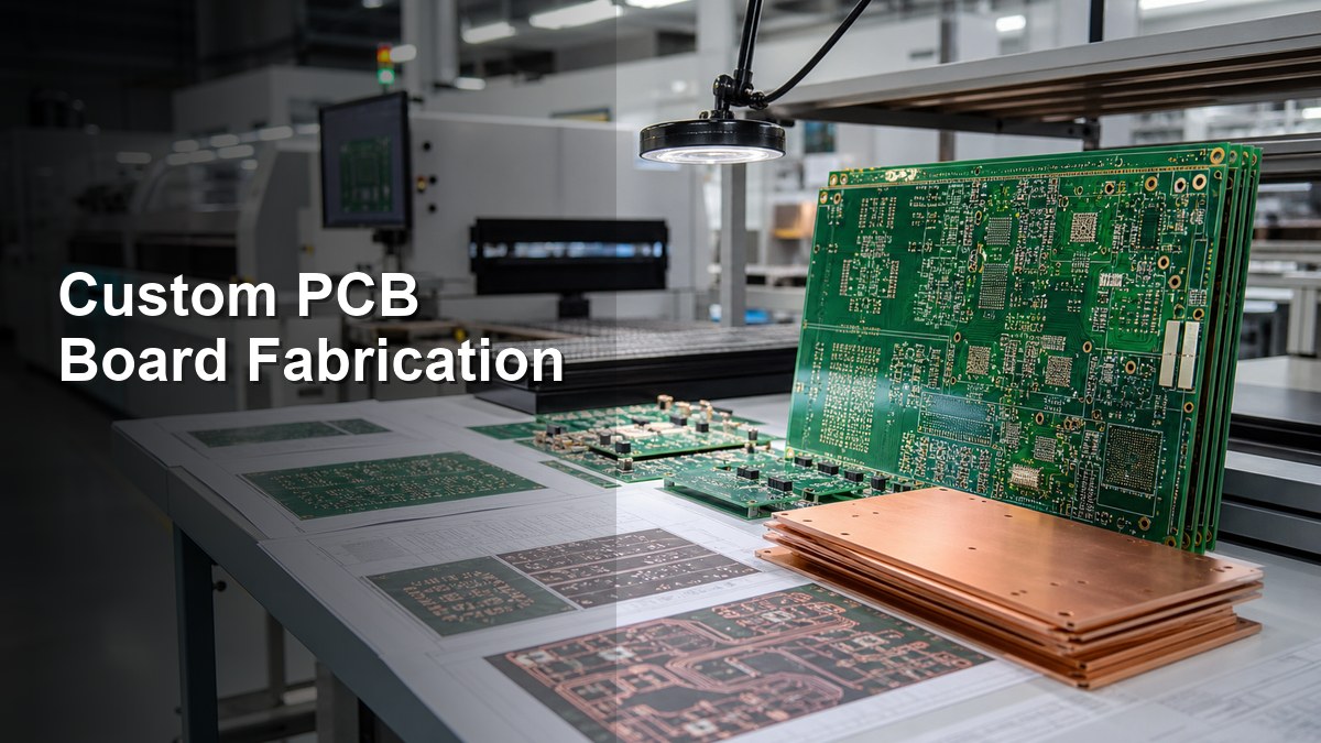
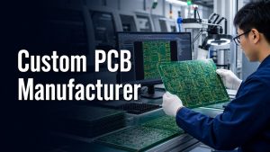
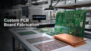
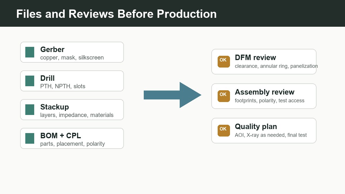
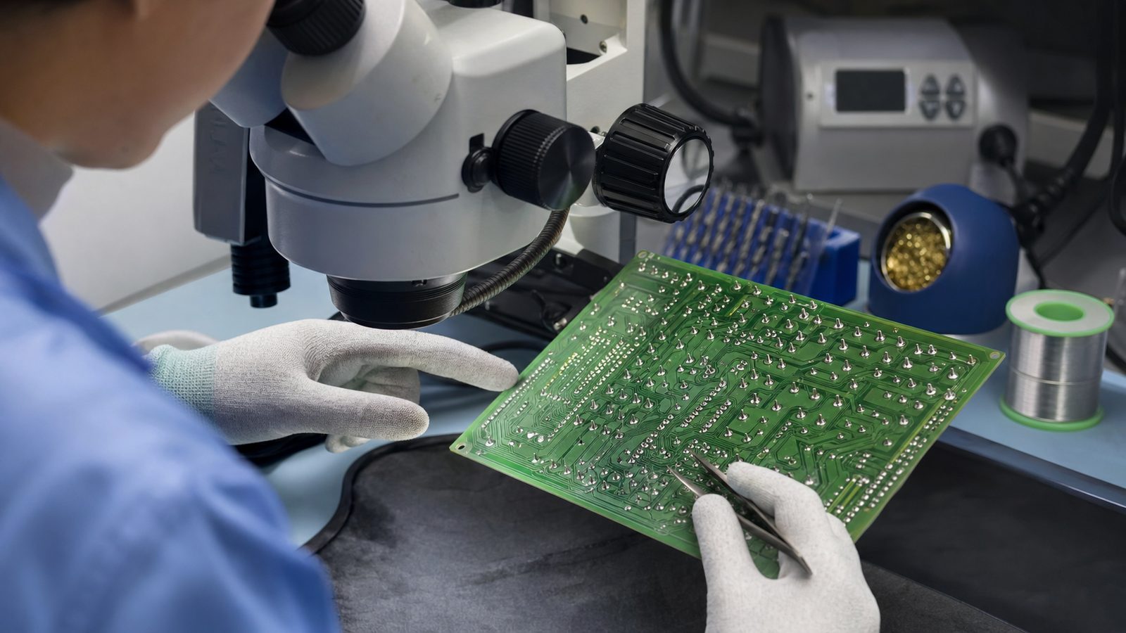
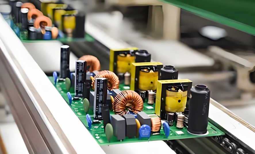
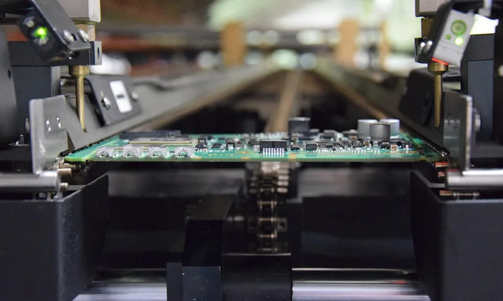
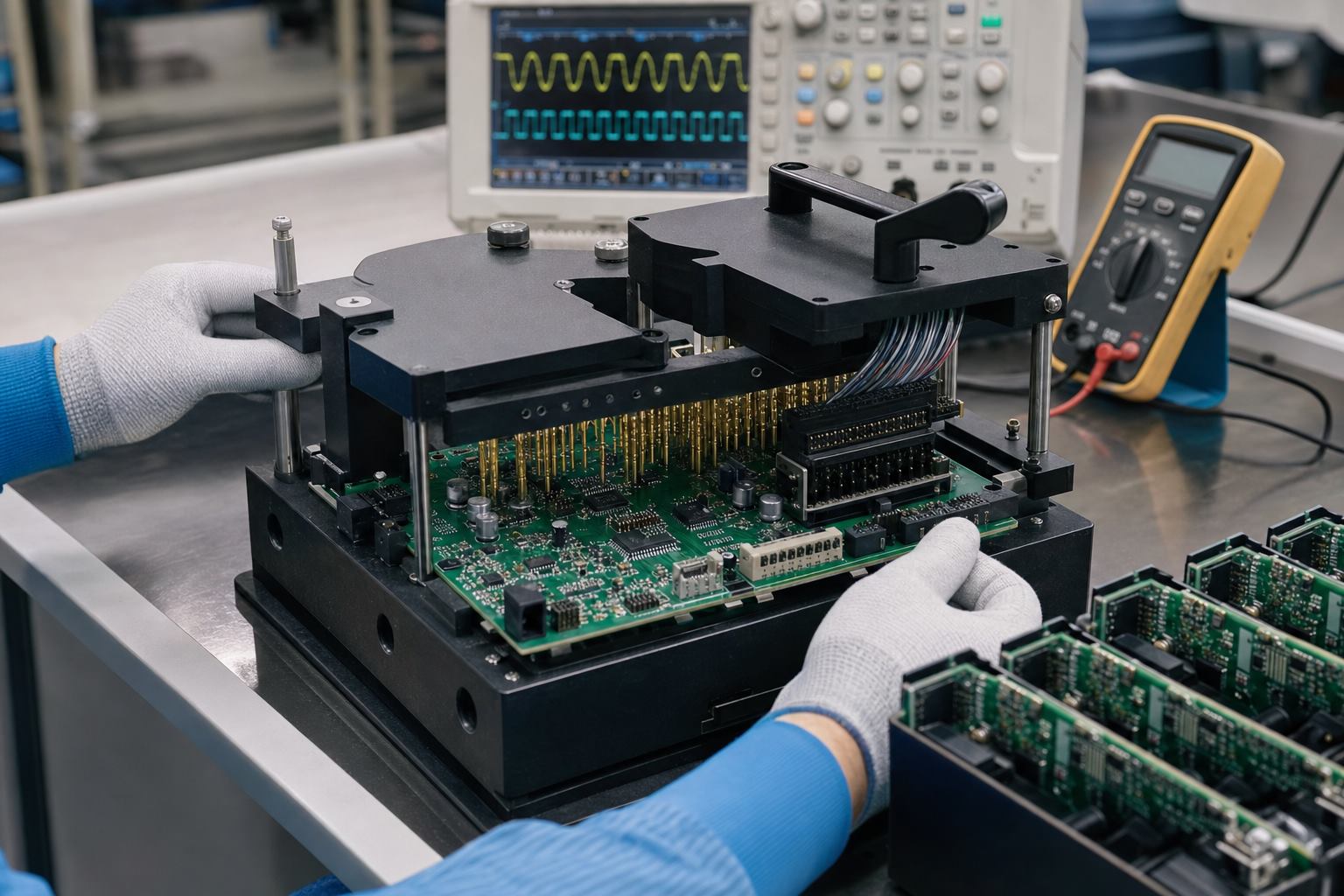
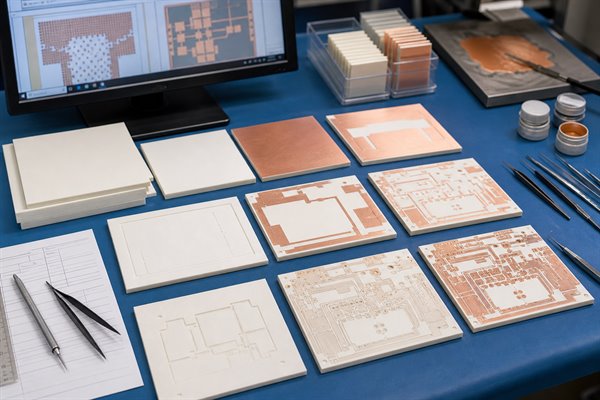
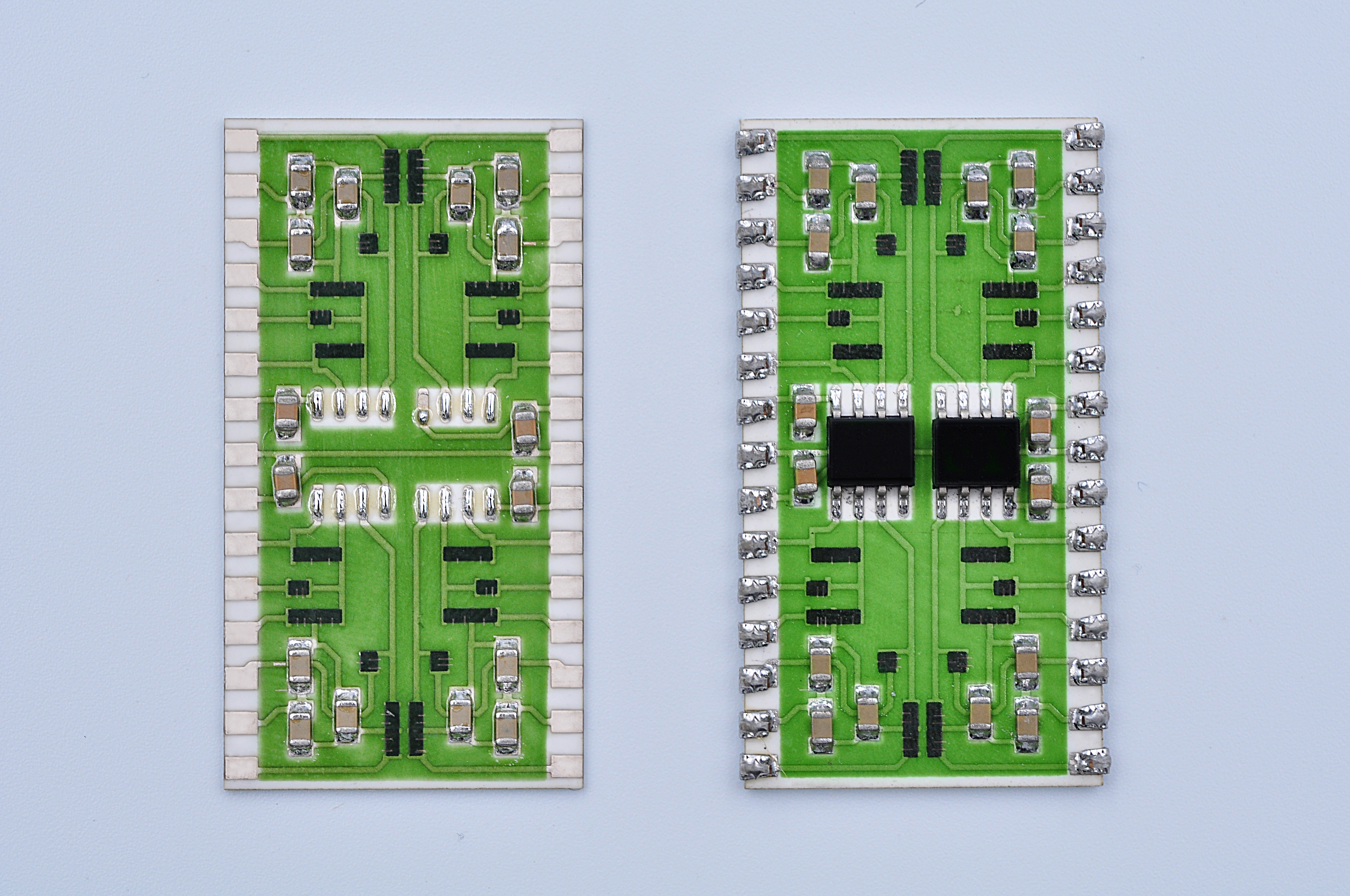
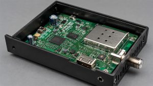
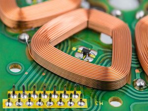
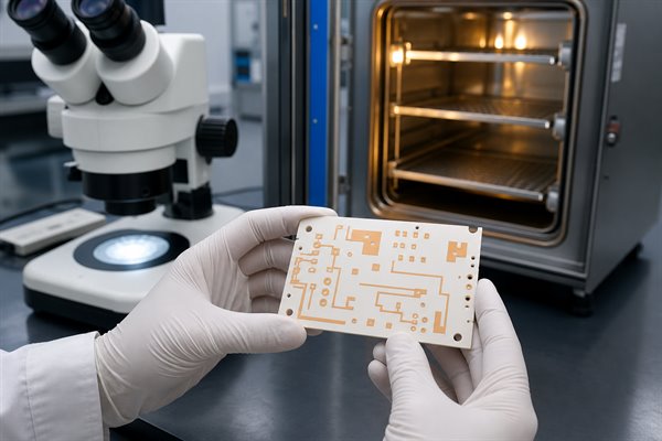
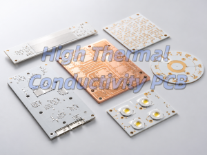
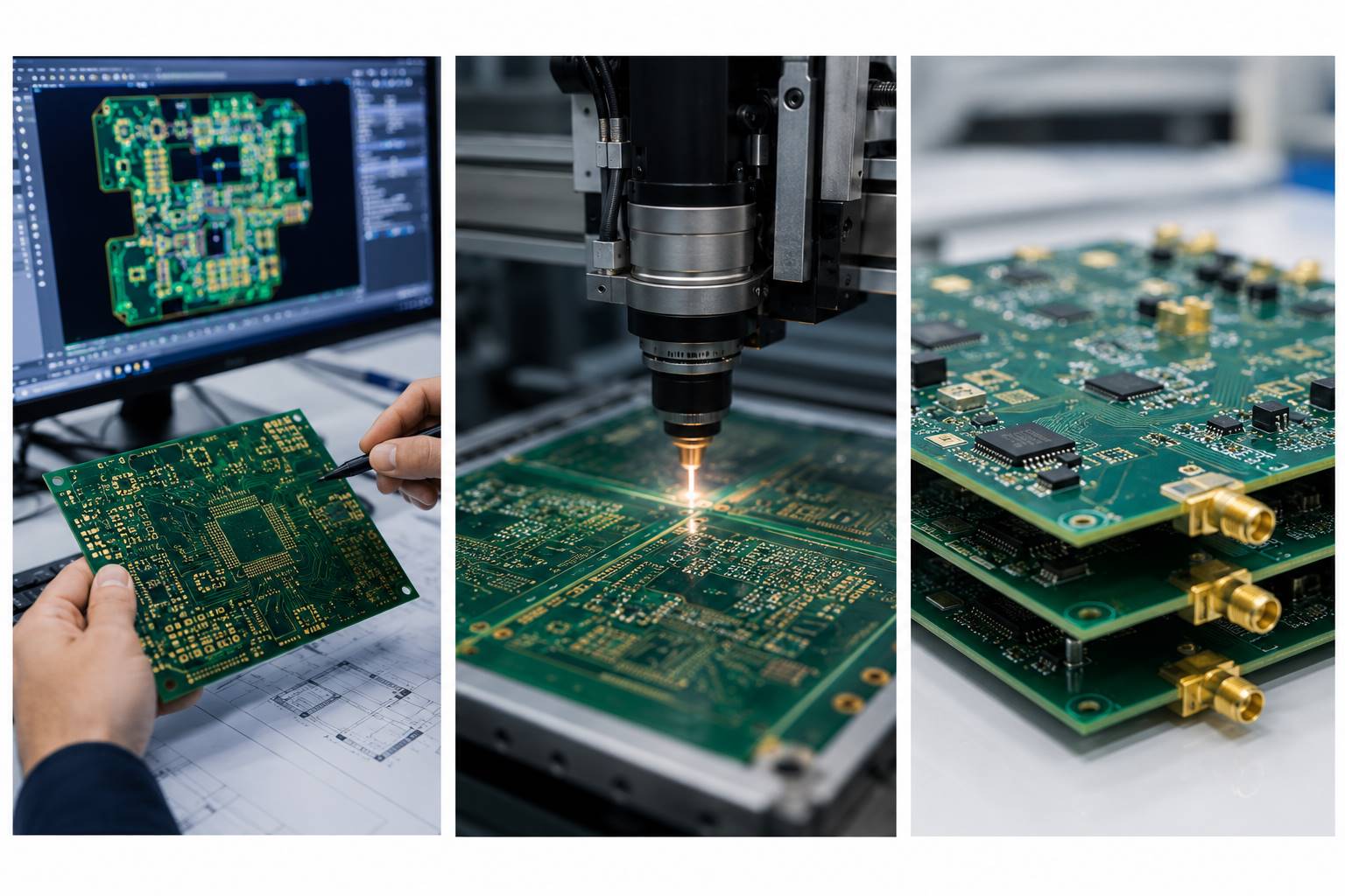
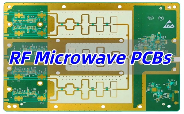
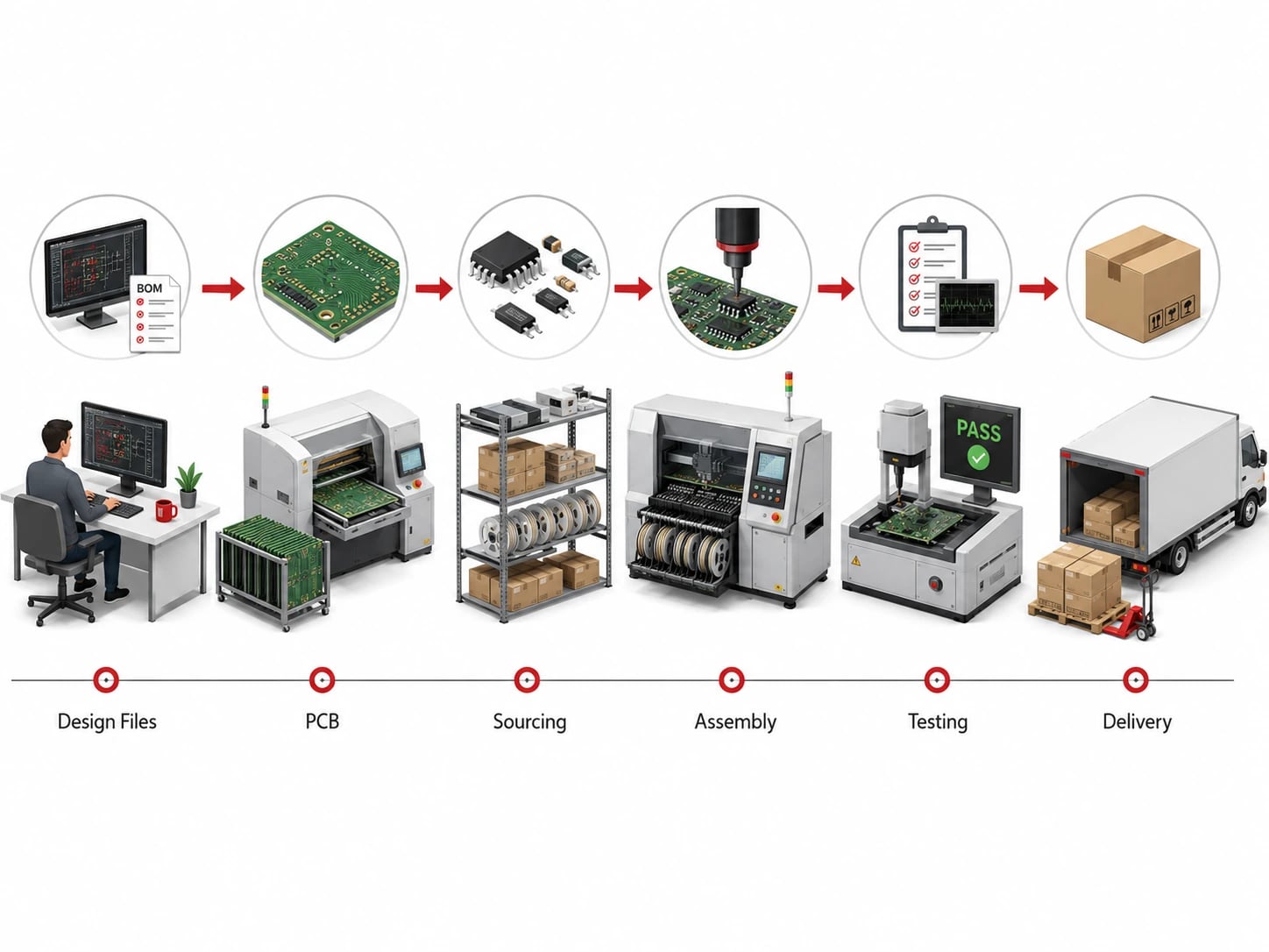
Custom PCB board fabrication works best when the supplier can review the design intent, materials, stackup and inspection needs before production starts.
Custom PCB board fabrication is the process of turning production-ready design data into a physical printed circuit board built to a specific stackup, material, copper weight, surface finish, tolerance and inspection requirement. A reliable fabrication order is not defined only by board size or layer count. It depends on clean Gerber or ODB++ data, drill files, material availability, manufacturable design rules, controlled process steps and clear acceptance criteria.
For engineers and buyers, the most useful question is not simply “who can make a custom PCB?” The better question is “what information does the fabricator need to build this board correctly the first time?” This guide explains the file package, material decisions, fabrication steps, inspection checks and supplier questions that matter before RFQ.
What Is Custom PCB Board Fabrication?
Custom PCB board fabrication means manufacturing a bare PCB from a customer-specific design rather than buying a standard off-the-shelf board.
The design may be a simple two-layer FR4 board, a dense multilayer board, an HDI board, a heavy copper power board, a metal-core board, a ceramic substrate, or another application-specific construction. The fabricator prepares production tooling from the supplied data, images the copper layers, drills holes, plates vias, applies solder mask and legend, adds the chosen surface finish, routes or scores the outline, and tests the board before shipment.
A custom board gives the designer control over shape, connector position, layer structure, impedance, copper width, heat path, mounting holes and assembly fit. That control also creates responsibility: unclear design notes, missing drill files or unrealistic tolerances can delay production or create boards that are technically built but not suitable for the final product.
Files Needed Before a PCB Can Be Fabricated
A fabricator can only confirm price, lead time and manufacturability when the production file package describes the board without guessing.
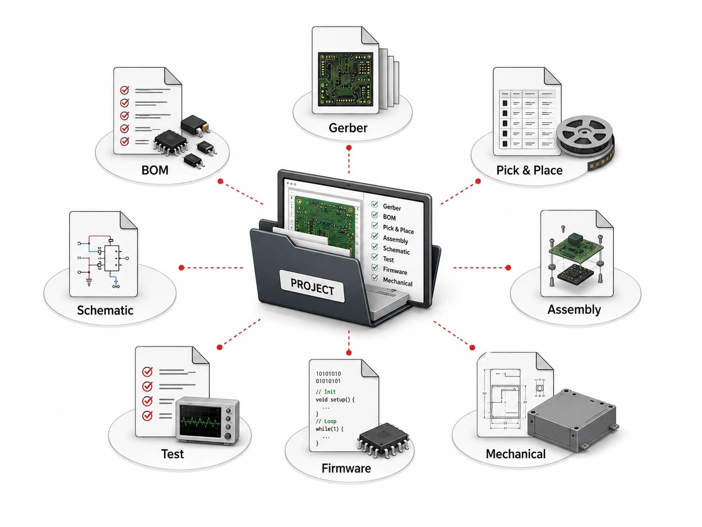
For bare PCB fabrication, send Gerber or ODB++ files, NC drill files, board outline, layer stackup, copper weight, finished thickness, material requirement, solder mask color, legend color, surface finish, impedance notes, controlled-depth drilling notes, special plating requirements and a fabrication drawing if tolerances matter. If the board will later be assembled, include the BOM, centroid file and assembly drawing early so the bare board can support the assembly process.
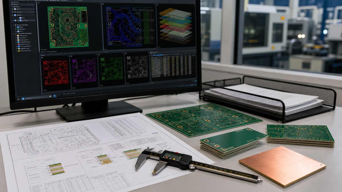
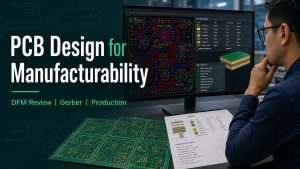
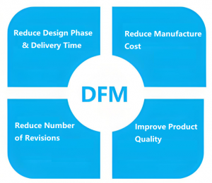
File review should catch stackup, drill, outline, material and tolerance issues before the board enters production.
Common file problems include an outline that does not match the mechanical drawing, plated and non-plated holes mixed in one unclear drill file, missing impedance information, no material callout, ambiguous copper weight, or a solder mask opening that conflicts with fine-pitch parts. These problems are easier to fix before fabrication than after panels are released to production.
Material and Stackup Choices That Change Fabrication Risk
Material and stackup decisions control cost, lead time, yield and long-term reliability more than many buyers expect.
Standard FR4 printed circuit board builds are usually easier to quote and schedule than special laminates. However, high Tg FR4, RF material, ceramic substrate, metal-core construction, rigid-flex material and heavy copper boards may be necessary for temperature, power, frequency or mechanical requirements. The right material should be chosen for the operating environment, not only for the lowest unit price.
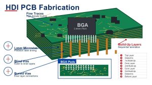
Stackup also matters. Controlled impedance, sequential lamination, buried vias, blind vias, via-in-pad, thin dielectric spacing and unusual finished thickness can all add manufacturing checks. If the design needs high wiring density, compare the layout against realistic HDI PCB process limits before asking for fast delivery.
Typical PCB Fabrication Steps Buyers Should Understand
The fabrication process is a controlled chain of imaging, drilling, plating, finishing and testing steps, so a weak early decision can affect the final board.
Stage
What Happens
Buyer Check
CAM and DFM review
Files are checked for manufacturability, layer alignment, drill data, spacing and special notes.
Confirm all design files match the intended revision.
Material preparation
Copper-clad laminate, prepreg, copper foil and special materials are prepared.
Verify material grade, board thickness and copper weight.
Inner and outer layer imaging
Copper patterns are transferred and etched according to the design data.
Check fine line and spacing against supplier capability.
Drilling and plating
Mechanical or laser holes are drilled, then plated to connect layers.
Review hole size, annular ring and aspect ratio risk.
Solder mask and surface finish
Solder mask, legend and finish such as HASL, ENIG, OSP or immersion silver are applied.
Select a finish that fits component type, shelf life and assembly method.
Profiling and testing
Boards are routed, V-scored, electrically tested and inspected before packing.
Define acceptance criteria and required reports before production.
For a broader process reference, Best Technology’s PCB manufacturing page shows how raw material preparation, lamination, drilling, plating, solder mask, testing and packing fit together in a complete bare-board flow.
This PCB process video is used as a visual supplement only; the checklist above should still be reviewed in text before RFQ.
Design Rules That Should Be Checked Before RFQ
DFM review should focus on the few design limits that can change yield, price or delivery before the buyer approves production.
Minimum trace width and spacing for the chosen copper weight.
Minimum mechanical drill, laser drill and finished hole size.
Annular ring, drill-to-copper clearance and edge-to-copper clearance.
Aspect ratio for plated through holes and microvia structure for HDI boards.
Solder mask bridge width for fine-pitch components.
Controlled impedance stackup, dielectric thickness and copper roughness assumptions.
Panelization, V-score or routing needs for assembly handling.
Surface finish compatibility with BGA, fine pitch, wire bonding or storage conditions.
If the project includes SMT, through-hole assembly or turnkey sourcing, bare board fabrication should be planned with PCB assembly support in mind. Pad design, fiducials, panel rails, solder mask openings and test points can make assembly easier or create avoidable rework.
Inspection and Testing Should Be Defined Early
Inspection should match the risk level of the board, not a generic checklist copied from another project.
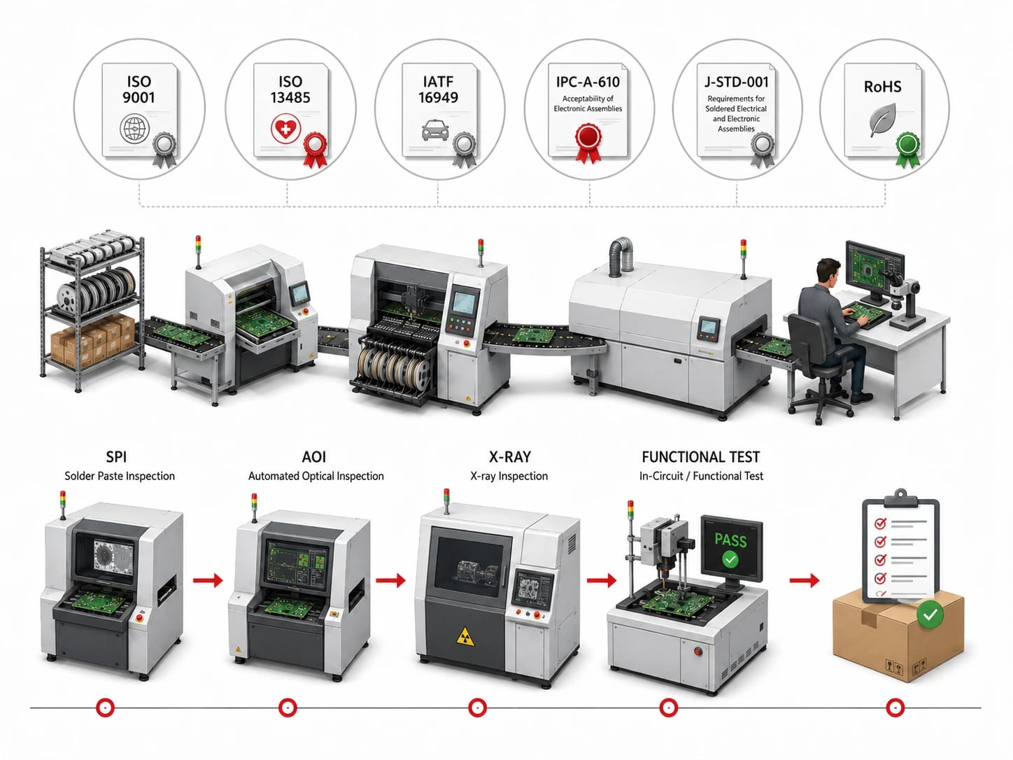
Typical checks include visual inspection, dimensional measurement, solder mask inspection, electrical open/short testing, impedance coupon testing when specified, microsection review for high-reliability builds, and final packing inspection. For boards used in power electronics, automotive equipment, medical devices, aerospace-related hardware or outdoor products, buyers should define the required standard, report format and acceptance level before quotation.
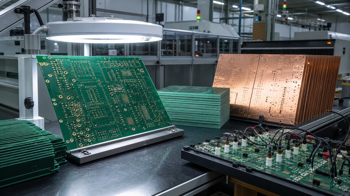
Electrical testing, visual inspection and process records help confirm that the fabricated boards match the approved design data.
Quality checks are also practical supplier filters. A fabricator that can explain test equipment, inspection points and process records is usually easier to work with than one that only quotes a low price. Best Technology’s PCB test equipment page is a useful internal reference when a buyer wants to understand what inspection capability may be relevant.
Cost and Lead Time Factors in Custom PCB Fabrication
Custom PCB fabrication cost and lead time usually increase when the board needs more controlled process steps or less common material.
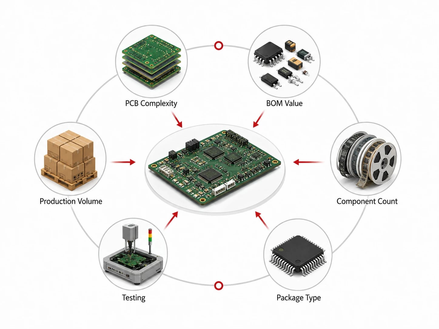
Important cost drivers include layer count, panel utilization, board thickness, copper weight, line width and spacing, hole count, smallest drill, blind or buried vias, surface finish, impedance control, special material, testing requirements, quantity and delivery speed. A small board is not always cheap if it requires HDI, heavy copper, tight drilling or special laminate. A larger board may be easier if it uses standard material and relaxed tolerances.
Buyers should ask suppliers to separate tooling, bare board fabrication, assembly, component sourcing, testing and shipping costs when the project includes more than the bare PCB. This prevents a low board price from hiding a high assembly or logistics risk.
Supplier Questions Before You Approve Fabrication
The best RFQ questions help the supplier expose manufacturing risk before the board enters production.
Are any traces, spaces, holes or annular rings outside standard capability?
Is the requested material in stock, or does it require special sourcing?
Does the stackup support the required impedance and finished thickness?
Is the selected surface finish suitable for the component packages and storage time?
Are there any panelization issues that could affect assembly or depaneling?
Which tests are included, and which reports require an extra request?
What design change would reduce cost, lead time or yield risk?
If the design falls outside standard FR4 or routine multilayer production, a special PCB review can help clarify whether the project needs heavy copper, high-frequency material, metal core, ceramic, rigid-flex or another custom process path.
FAQ
What files are required for custom PCB board fabrication?
Most fabrication orders need Gerber or ODB++ files, NC drill files, board outline, stackup, copper weight, thickness, material, solder mask, legend, surface finish and any special tolerance notes. A fabrication drawing is useful when dimensions, impedance, controlled-depth drilling or acceptance criteria matter.
Is PCB fabrication the same as PCB assembly?
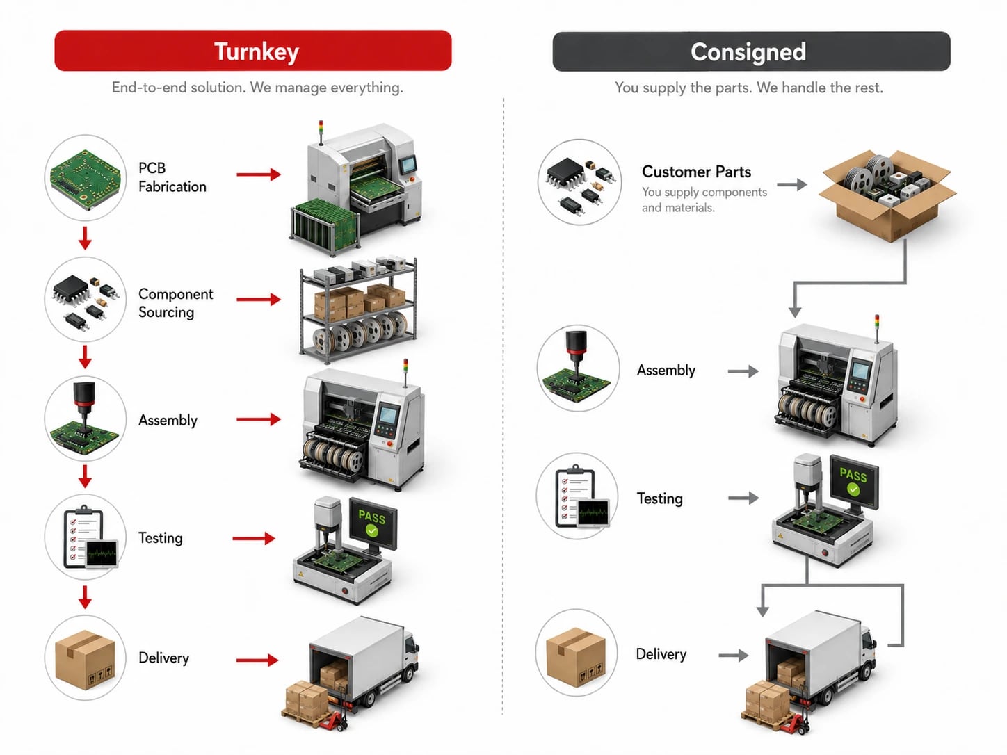
No. PCB fabrication makes the bare printed circuit board. PCB assembly places and solders components onto that board. A turnkey PCBA project needs both steps, plus BOM review, component sourcing, stencil planning, inspection and testing.
What makes a custom PCB harder to fabricate?
HDI microvias, blind or buried vias, heavy copper, tight spacing, unusual thickness, special materials, controlled impedance, fine-pitch solder mask, large panels and strict inspection requirements can all increase fabrication difficulty.
Which surface finish should I choose?
The right finish depends on assembly method, component package, shelf life, flatness and cost. ENIG is often chosen for fine pitch and flatness, HASL can fit less demanding boards, and OSP may fit some cost-sensitive builds. Confirm with the assembler before ordering.
How can I reduce PCB fabrication cost?
Use standard material when possible, improve panel utilization, avoid unnecessary tight tolerances, simplify via structures, keep copper weight realistic, choose a suitable finish and send complete files. Do not remove inspection that protects product reliability.
Can a fabricator fix my PCB design files?
A fabricator can often flag manufacturability issues and suggest changes, but it should not silently change electrical intent. Any change to spacing, pad shape, drill size, stackup or material should be reviewed and approved by the design owner.
When should I request impedance control?
Request impedance control when the board carries high-speed digital, RF, differential pairs, antennas or other signals that depend on trace geometry and dielectric structure. Provide target impedance, tolerance, reference layers and stackup requirements.
Does custom PCB fabrication always take longer than standard PCB orders?
Not always. A custom board with standard FR4, clean files and routine tolerances can move quickly. Lead time increases when the design needs special material, complex stackup, extra testing, unusual finish or unresolved DFM clarification.
Final Thoughts
Custom PCB board fabrication is predictable when the design files, stackup, material choices, process limits and inspection requirements are clear before production. The safest RFQ is not the one with the fewest details. It is the one that lets the supplier identify cost, lead time and yield risk before the first panel is built.
If you are preparing a custom PCB for prototype or production, send your Gerber, drill, stackup, BOM and assembly files to the Best Technology engineering team at sales@bestpcbs.com for fabrication, PCBA and quotation review.
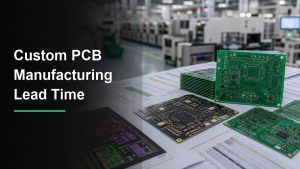
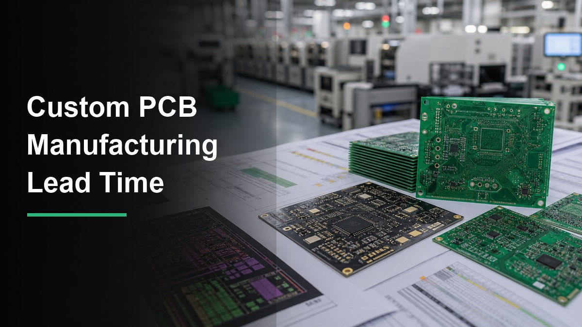
Custom PCB lead time is easier to control when design files, materials, production steps and inspection needs are reviewed before quotation.
Custom PCB manufacturing lead time is the time from approved production files and quote confirmation to finished boards or assembled PCBAs ready for shipment. It is not set only by layer count. File quality, material availability, surface finish, copper weight, impedance control, component sourcing, testing scope, production queue and shipping route can all add or remove days.
For buyers, the practical question is not “what is the fastest possible PCB lead time?” The better question is “what information does the factory need to confirm a reliable lead time for this exact board?” A simple FR4 prototype with complete Gerbers can move quickly. A custom PCB with HDI, controlled impedance, special laminate, heavy copper, tight drilling, turnkey assembly or functional testing needs a more careful schedule.
What Counts as Custom PCB Manufacturing Lead Time?
Custom PCB manufacturing lead time should be counted after the supplier has approved the production data, confirmed materials and accepted the order, not from the first email.
A realistic timeline usually includes engineering review, quotation clarification, material preparation, bare board fabrication, surface finish, electrical test, optional assembly, final inspection, packing and logistics. If the project includes turnkey PCBA, component sourcing and incoming parts inspection must be counted separately from bare PCB fabrication.
This is why two boards with the same layer count can have different schedules. A standard 4-layer FR4 board with common finish may be simple. A similar-looking 4-layer board with unusual thickness, special copper, impedance coupons, tight annular rings, press-fit connectors or high-reliability testing may need more review and queue time.
Typical Lead Time Stages Buyers Should Separate
The most useful lead time estimate separates engineering review, PCB fabrication, assembly, testing and shipping instead of giving one vague number.
Stage
What Happens
Common Delay Trigger
Buyer Action
Engineering review
Gerber, drill, stackup, drawing, BOM and assembly data are checked.
Missing notes, unclear tolerances, mismatched drill files or incomplete BOM.
Send a complete file package and answer DFM questions quickly.
Material preparation
Laminate, copper, prepreg, solder mask and components are reserved.
Special laminate, high Tg, RF material, ceramic substrate or allocated components.
Approve alternates early and confirm critical material rules.
PCB fabrication
Imaging, etching, lamination, drilling, plating, solder mask and finish are completed.
Keep the first build inside standard capability when schedule matters.
PCBA assembly
Stencil, SMT placement, reflow, through-hole work, cleaning and inspection are performed.
Long-lead components, BGA/X-ray needs, mixed SMT/THT, fixture setup or programming.
Confirm BOM availability and provide placement, polarity and test notes.
Inspection and logistics
AOI, electrical test, visual inspection, packing and shipment are arranged.
Extra test reports, rework, customs documents or remote shipping destination.
Define required reports and shipping method before production starts.
Files That Shorten or Delay a Custom PCB Schedule
Complete files shorten lead time because the factory can quote, review and release production without repeated clarification.
For bare PCB fabrication, send Gerber or ODB++ files, NC drill files, board outline, stackup requirement, copper weight, board thickness, solder mask color, silkscreen color, surface finish, impedance notes, controlled-depth drilling notes and any special acceptance criteria. For PCBA, add BOM, centroid or pick-and-place file, assembly drawing, polarity notes, firmware or programming instructions, and test requirements.
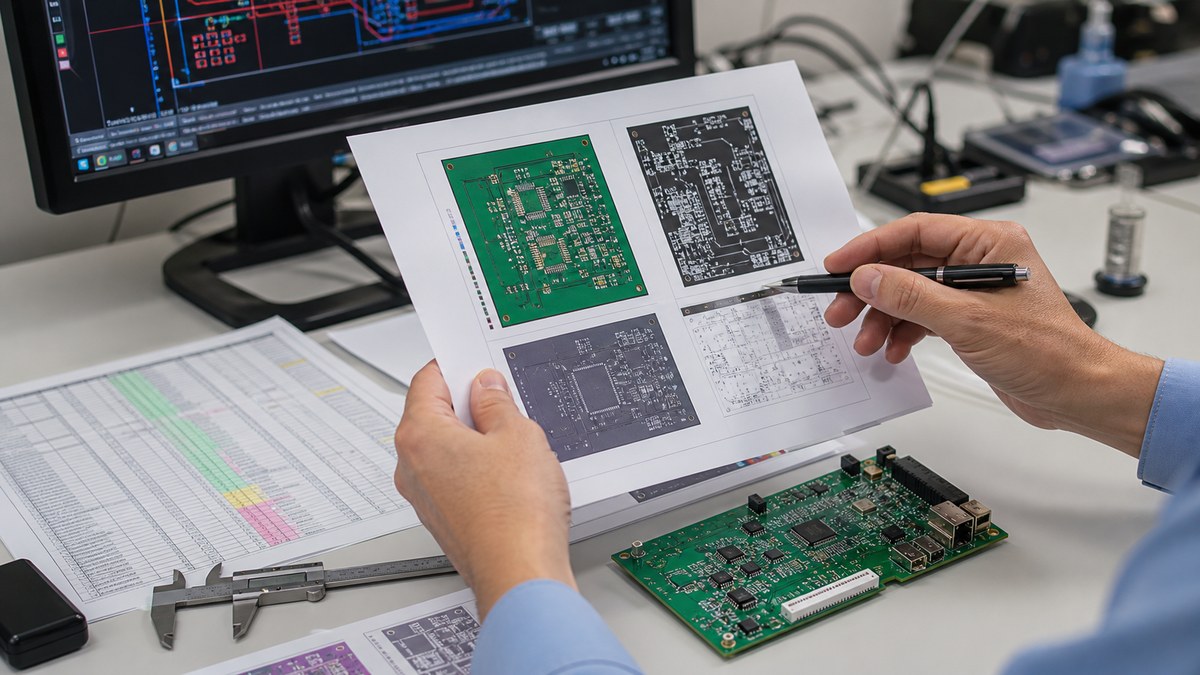
Incomplete Gerber, BOM, stackup or assembly notes can turn a quick-turn request into a clarification loop.
A common delay is a file set that looks complete but has contradictions. Examples include a board outline that does not match the mechanical drawing, a BOM package that does not match the centroid file, a stackup note that conflicts with impedance requirements, or a surface finish choice that is not suitable for the component package. These issues should be solved before the purchase order is treated as production-ready.
Board Complexity Has More Impact Than Board Size Alone
Lead time usually increases when the board requires more controlled process steps, tighter inspection or less common materials.
Layer count matters, but it is only one part of the schedule. HDI microvias, blind or buried vias, sequential lamination, heavy copper, fine line and space, controlled impedance, unusual thickness, rigid-flex construction and special surface finishes can all add review and production time. If a project needs HDI density, review the board against realistic HDI PCB manufacturing limits before asking for rush delivery.
Material choice also matters. Standard FR4 is usually easier to schedule than a special laminate, ceramic substrate, metal core PCB, RF material or high-temperature stackup. If standard FR4 is acceptable, the FR4 printed circuit board route may reduce sourcing risk. If the design needs special thermal, high-frequency or structural behavior, lead time should include material confirmation.
PCBA Lead Time Depends on Components, Not Only Assembly Speed
For turnkey PCBA, component availability often controls the real delivery date more than placement speed.
A factory may be able to assemble a small batch quickly once all parts are ready, but that does not mean every assembled board can ship quickly. Long-lead ICs, connectors, magnetics, sensors, relays, custom cables, displays and odd passives can delay the start of assembly. If the BOM has obsolete, allocated or region-specific parts, schedule risk should be discussed before the order is placed.
When schedule matters, confirm whether the supplier can support component sourcing, approved alternates, incoming inspection and shortage reporting. A practical BOM review should identify no-stock items, risky single-source parts, package mismatches and parts that require programming or special handling.
When Quick-Turn PCB Manufacturing Is Realistic
Quick-turn service is realistic when the design uses available materials, complete files and a process flow that fits the factory queue.
Fast schedules work best for simple prototypes, standard materials, small or medium panel sizes, common finishes, clean drill data, no unresolved DFM issues and components that are already in stock. A quick-turn request becomes less reliable when the board needs special laminate, multiple lamination cycles, unusual solder mask, tight impedance tolerance, large panels, heavy copper, fixture-based testing or long-lead components.
For assembled prototypes, a dedicated prototype PCB assembly flow can help engineering teams validate a design before locking mass production. If the project must move from prototypes into larger volumes, quick turn PCB assembly should be planned with component supply and test coverage in mind.
Rush Fees Do Not Fix Every Lead Time Problem
Expedited service can compress queue time, but it cannot remove engineering, material or component constraints that still need resolution.
Rush delivery is most useful when the files are clean and the process is standard. It is less useful when the supplier still needs to clarify impedance, stackup, plating, tolerances, test methods, part substitutions or acceptance criteria. Paying for speed before the file package is stable can create rework rather than faster delivery.
A better approach is to ask the supplier which step controls the schedule. If the answer is material sourcing, choose an available material or accept a longer lead time. If the answer is DFM risk, revise the design. If the answer is component shortage, approve alternates or split the build. If the answer is production queue, expedited service may help.
How to Prepare an RFQ for a Reliable Lead Time
A lead-time-ready RFQ should let the supplier quote the board without guessing about design intent, assembly scope or acceptance criteria.
Send the final Gerber or ODB++ package, NC drill files and board outline.
Include stackup, copper weight, board thickness, material preference and surface finish.
Mark impedance, controlled-depth drilling, press-fit holes, castellations or edge plating if used.
For PCBA, send BOM, centroid file, assembly drawing, polarity notes and testing requirements.
State the target quantity, prototype or production purpose, required delivery date and shipping country.
List any parts that cannot be substituted and any parts where alternates are allowed.
Ask the supplier to separate fabrication, component sourcing, assembly, testing and shipping time.
Lead Time Risk Checklist Before You Approve Production
Before approval, check the schedule against the real manufacturing risks instead of accepting a single optimistic delivery date.
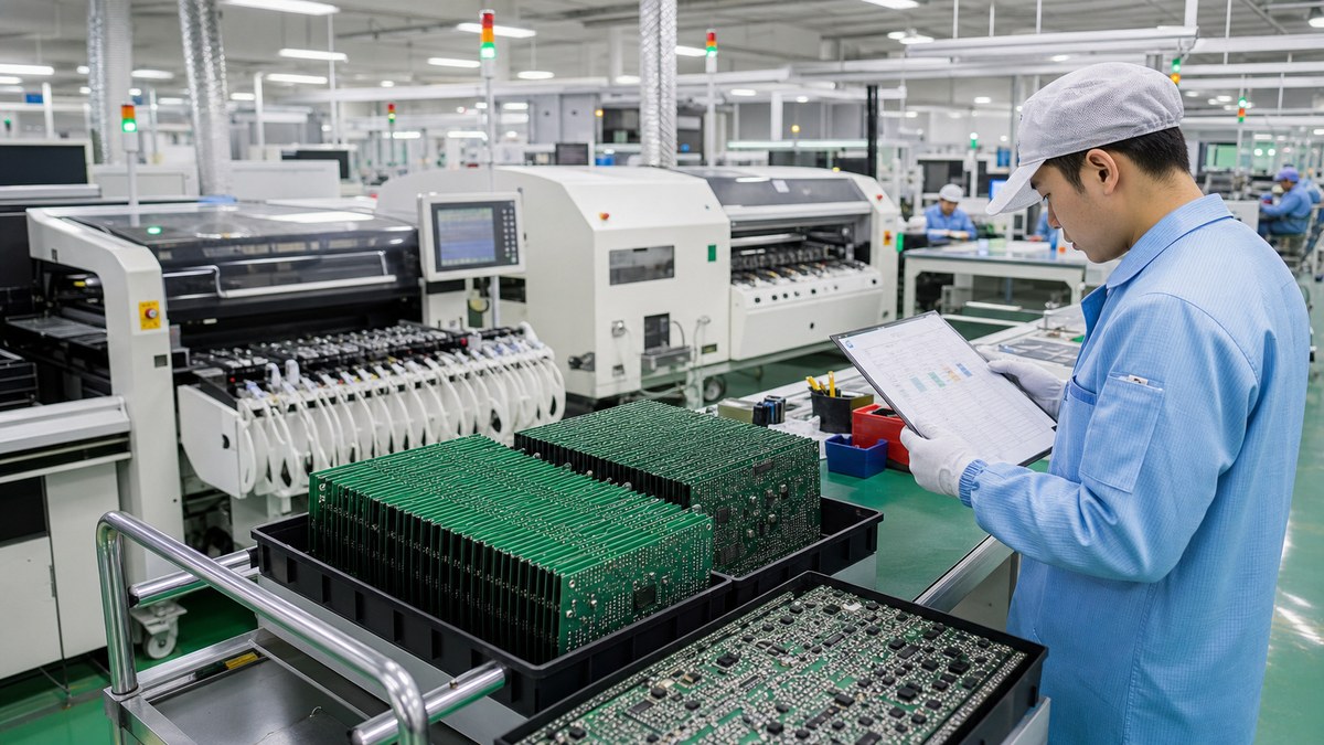
Production lead time should include fabrication, assembly, inspection, packing and logistics, not only machine time.
Are all production files approved and version-controlled?
Are laminate, copper, solder mask and surface finish available?
Do all critical components have stock, alternates or confirmed purchase dates?
Does the board need impedance testing, flying probe, fixture test, AOI, X-ray or functional test?
Does the first article require engineering approval before the full batch continues?
Are packaging, labeling, customs documents and shipping method already defined?
Is the promised date based on working days, calendar days or shipment date?
How to Reduce Custom PCB Manufacturing Lead Time Without Raising Risk
The safest way to reduce lead time is to remove uncertainty before production starts.
Use standard materials when possible, keep the first prototype inside common capability, avoid unnecessary special finishes, release a clean BOM, allow qualified alternates and answer DFM questions fast. For PCBA, order critical long-lead components early or let the supplier source parts before the bare boards are finished. For repeat builds, keep the same approved stackup, finish, stencil and test plan unless a change is necessary.
Do not shorten lead time by skipping review on a high-risk board. A missed annular ring issue, wrong footprint, unavailable connector or unclear test requirement can cost more time than a proper review. Good suppliers should be willing to explain the bottleneck instead of only quoting the fastest possible date.
Supplier Questions That Reveal Whether the Schedule Is Reliable
Ask schedule questions that force the supplier to show where the lead time comes from.
When does your lead time clock start: quote approval, payment, file approval or material arrival?
Which step is the current bottleneck for this board?
Are the laminate, solder mask, surface finish chemicals and critical components already available?
What changes would shorten the lead time without weakening reliability?
Does the quote include electrical test, AOI, X-ray, functional test or only basic inspection?
Will the promised date be shipment date or arrival date?
What happens if DFM review finds a file issue after order approval?
FAQ About Custom PCB Manufacturing Lead Time
These answers are written for buyers preparing an RFQ, not for one fixed factory schedule.
How long does custom PCB manufacturing take?
It depends on board complexity, material availability and whether assembly is included. Simple prototypes can move much faster than HDI, rigid-flex, ceramic, heavy copper or fully assembled PCBAs. Treat any published number as a starting point and ask for a quote based on your actual files.
When should I start counting PCB lead time?
Count lead time after production files are approved, the order is confirmed and required materials or components are available. Early emails, incomplete Gerbers or unresolved BOM questions should not be treated as production time.
What files are needed to confirm custom PCB lead time?
For bare boards, send Gerber or ODB++ files, drill files, board outline, stackup, material, thickness, copper weight and finish. For PCBA, add BOM, centroid file, assembly drawing, polarity notes and test requirements.
Does PCBA always add more lead time than bare PCB fabrication?
Usually yes, because assembly needs stencil preparation, component sourcing, placement, soldering, inspection and sometimes testing. The largest delay is often component availability, not the placement process itself.
Can I reduce lead time by using standard FR4?
Often yes. Standard FR4, common board thickness, common copper weight and common surface finish are easier to schedule than special laminate, ceramic, RF material, metal core, rigid-flex or unusual process requirements.
What makes HDI or rigid-flex boards slower?
HDI and rigid-flex designs may need sequential lamination, laser drilling, tighter registration, controlled impedance, special materials and extra inspection. These steps are useful, but they should be planned instead of treated like standard quick-turn FR4 work.
Do rush fees guarantee delivery?
No. Rush fees may reduce queue time, but they cannot remove material shortages, unresolved DFM issues, unavailable components or unclear test requirements. Ask which step controls the schedule before approving an expedite charge.
How can I avoid delays after placing the order?
Freeze the file revision, respond to DFM questions quickly, approve part alternates early, confirm test requirements and avoid changing quantity, finish or shipping method after production starts.
Should I split prototypes and production into separate orders?
For new designs, yes in many cases. A prototype order can validate the layout, BOM, assembly process and test plan before a larger production batch. This reduces the risk of repeating an error at volume.
What should a supplier include in a clear lead time quote?
The quote should separate engineering review, material or component sourcing, bare PCB fabrication, assembly, inspection, packing and shipping. It should also state whether the date means completion, shipment or delivery.
Final Buying Advice
Custom PCB manufacturing lead time is predictable when the supplier sees the full design, confirms materials and separates each production stage. Before approving a rush order, ask what is slowing the schedule and whether a file, material or BOM change would reduce risk. If you are planning PCB fabrication, turnkey PCBA, prototypes or mass production, send your Gerber, BOM and assembly files to the Best Technology engineering team at sales@bestpcbs.com for a lead time and quotation review.
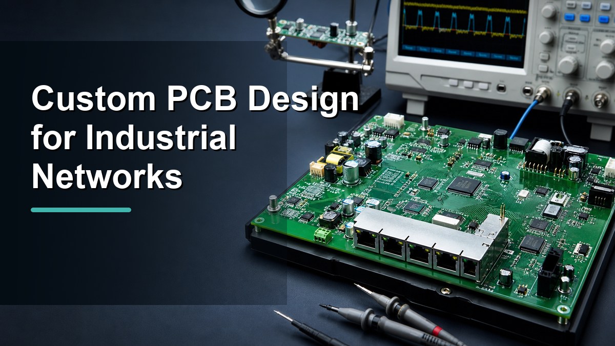
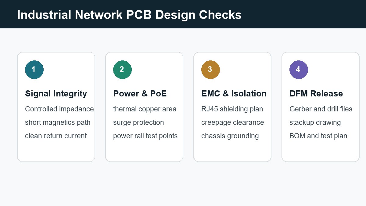
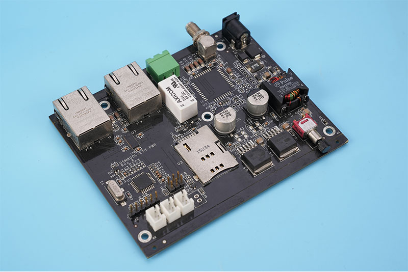
Industrial network PCB design should be reviewed around signal integrity, power, EMC, connector reliability, and production files before release.
Custom PCB design for industrial networks means building a printed circuit board for reliable data communication in machines, controllers, gateways, sensors, and field devices. The board must handle Ethernet or other network signals, stable power, EMC risk, connector stress, surge exposure, thermal load, and production repeatability at the same time.
For buyers and hardware engineers, the practical question is not only whether the circuit works on the bench. The real question is whether the PCB can be fabricated, assembled, tested, and used in a noisy industrial environment without repeated layout changes. That is why this article focuses on design checks, manufacturing files, and supplier review points for industrial network PCB projects.
What Is Custom PCB Design for Industrial Networks?
Custom PCB design for industrial networks is the process of creating a circuit board layout for devices that exchange data in factory, automation, monitoring, or machine-control environments.
These boards may support industrial Ethernet, RS-485, CAN, PoE, wireless modules, sensor interfaces, edge controllers, gateways, or mixed-signal control circuits. Unlike a generic development board, a custom industrial network PCB must fit the product enclosure, connector position, cable strain, operating temperature, power budget, and final assembly process.
The design work usually starts from schematic and layout, but it should not end there. The PCB also needs stackup definition, impedance planning, connector footprint control, ESD and surge protection, test access, and a manufacturable release package. For projects that need custom board types, review the available custom PCB and PCBA solutions early instead of waiting until the layout is already locked.
Where Industrial Network PCBs Are Used
Industrial network PCBs are used wherever electronic equipment must communicate reliably with other devices under electrical noise, vibration, temperature variation, or long cable runs.
Sensor front end, wireless or wired data link, compact shape
Analog noise, grounding, enclosure fit
PoE devices
Ethernet data and power on the same cable
Power loss, isolation, surge protection
Machine vision or control boards
High-speed data, stable power rails, edge connectors
Signal integrity, thermal rise, BOM stability
These applications often combine digital communication, power conversion, and field wiring on one board. That combination is useful, but it also creates design conflicts. The layout must keep noisy switching loops away from magnetics and data traces, give connectors enough mechanical support, and leave enough room for inspection and rework.
Key Design Checks Before Layout Release
The most useful pre-release checks are signal integrity, PoE or power design, EMC and isolation, connector reliability, and DFM file readiness.
Keep the design review focused on the checks that change manufacturing yield, field reliability, and debug time.
Start with the communication path. Ethernet differential pairs, high-speed sensor buses, and clock lines need controlled routing, short return paths, and careful spacing from switching power sections. If the product uses dense connectors or fast edge rates, a standard board may not be enough. In those cases, HDI PCB or tighter multilayer routing may be part of the design discussion.
Next, review power and thermal behavior. PoE, DC input modules, relays, and motor-control interfaces can push current through small board areas. Trace width, copper weight, thermal vias, fuse position, TVS diode placement, and connector current rating should be checked together. A layout that passes electrical simulation can still fail in production if heat concentrates under one regulator or if field wiring injects surge current into the wrong ground path.
Finally, check how the board will be assembled and inspected. An industrial network PCB often has RJ45 connectors, shield cans, terminal blocks, optocouplers, magnetics, LEDs, and test points. Footprint polarity, component height, solder access, and panelization should be reviewed before prototype order. If the project includes mounted components, plan the PCB assembly support at the same time as bare board fabrication.
How Stackup and Materials Affect Network Reliability
Stackup and material choice affect impedance stability, EMI behavior, thermal movement, and long-term reliability more than many buyers expect.
For many industrial control boards, FR4 is still the correct starting point. The decision is not simply “FR4 or special material.” Engineers should define board thickness, copper weight, layer count, reference planes, dielectric spacing, and operating temperature before asking for a quote. A controlled stackup helps keep Ethernet pairs consistent, gives return current a clean path, and reduces layout guesswork.
When the product must handle higher heat, tighter size, high-density connectors, or higher data rates, the board may need high Tg FR4, multilayer construction, impedance control, heavy copper, or special process review. You can use a standard FR4 printed circuit board for many designs, but do not treat the laminate as a default afterthought. Material choice should follow the electrical, thermal, and mechanical load of the device.
EMC, ESD, and Isolation Checks
Industrial network PCB design should give noise and surge current a controlled path instead of letting it travel through sensitive logic or sensor circuits.
Ethernet, RS-485, CAN, and external sensor ports usually connect to cables that may run near motors, relays, power wiring, or long metal frames. That means the PCB must consider ESD, surge, common-mode noise, shielding, creepage distance, and grounding strategy. Protection components should sit near the connector, not deep inside the board after a long trace path.
For RJ45 Ethernet, the magnetics area, shield connection, chassis reference, and differential routing deserve a dedicated layout review. For isolated inputs or fieldbus connectors, isolation slots and clearance rules must be visible in the fabrication data. For noisy power sections, keep switching loops compact and do not route sensitive communication traces under them unless the stackup and return path are deliberate.
Connector and Mechanical Reliability
Connector reliability is a PCB design issue because the board must survive cable insertion, pull force, enclosure fit, and repeated maintenance.
Industrial network products often fail at practical mechanical points: cracked solder joints under heavy connectors, weak cable strain relief, poor board support near terminal blocks, or connector openings that do not line up with the enclosure. A custom PCB should place mounting holes, keepouts, stiff areas, and connector orientation before the layout becomes crowded.
If the board needs edge connectors, shielded RJ45 jacks, terminal blocks, or unusual cutouts, include mechanical drawings with the quote package. Special board shapes, gold fingers, impedance lines, and nonstandard copper requirements should be reviewed as special PCB items rather than handled as ordinary low-risk details.
Production File Checklist for an Accurate Quote
An accurate quote needs fabrication, assembly, mechanical, and testing information, not only a Gerber file.
A complete release package reduces quote assumptions and avoids avoidable engineering questions before production.
For bare PCB fabrication, send Gerber or ODB++ files, NC drill files, board outline, stackup request, copper thickness, surface finish, solder mask color, impedance requirements, special notes, and quantity. For assembly, add the BOM, pick-and-place file, assembly drawing, polarity notes, approved alternates, programming needs, and test requirements.
Do not hide special requirements inside email text only. Put them in the drawing or release note so CAM, procurement, assembly, and quality teams see the same information. If the project is still at prototype stage, prototype PCB assembly can help validate footprints, connector fit, and test points before scaling to a larger build.
Supplier Questions Buyers Should Ask
A supplier for industrial network PCB work should be able to discuss DFM, stackup, assembly, testing, and component risk before production starts.
Can you review the Ethernet or high-speed routing stackup before fabrication?
Can you confirm minimum annular ring, drill-to-copper clearance, and slot capability?
Can you assemble shielded connectors, magnetics, terminal blocks, and mixed SMT/THT parts?
How will polarity, connector orientation, and functional test access be checked?
Which components in the BOM need alternates or sourcing confirmation?
Can you separate bare PCB, assembly, and testing cost drivers in the quote?
BOM risk is often underestimated in custom industrial electronics. Ethernet magnetics, isolated power modules, TVS arrays, terminal blocks, and industrial connectors can have long lead times or multiple acceptable alternates. For that reason, component sourcing should be reviewed before the layout is frozen, especially when footprint-compatible alternates are possible.
Common Mistakes That Delay Industrial Network PCB Projects
Most delays come from unclear files, missing mechanical details, weak test planning, and design choices that are hard to build consistently.
A common mistake is sending only Gerbers when the project also needs controlled impedance, assembly, programming, and functional testing. Another is placing Ethernet connectors and surge protection after the rest of the board is already dense. That often leads to long protection paths, poor grounding, and last-minute compromises around the enclosure.
Buyers also sometimes compare quotes without checking assumptions. One supplier may quote bare boards only, while another includes assembly, component procurement, testing, and fixture work. A lower number is not useful if it excludes the work needed to make the product shippable.
FAQ About Custom PCB Design for Industrial Networks
What makes an industrial network PCB different from a normal PCB?
An industrial network PCB usually connects to cables, machines, sensors, or controllers in electrically noisy environments. It needs stronger attention to EMC, ESD, grounding, connector strength, power stability, test access, and production repeatability than a simple low-speed control board.
Do industrial Ethernet PCBs always need controlled impedance?
Not always, but Ethernet differential pairs and faster interfaces should be reviewed for impedance, stackup, routing length, pair spacing, and return path. If cable length, data rate, EMI risk, or product reliability matters, controlled impedance planning is safer than treating the traces as ordinary signal routes.
What files should I send for a custom industrial network PCB quote?
Send Gerber or ODB++ files, drill files, board outline, stackup, material and copper requirements, BOM, pick-and-place file, assembly drawing, impedance notes, testing requirements, and any enclosure or connector constraints. More complete files reduce quote assumptions.
Can one supplier handle both PCB fabrication and assembly?
Yes, but confirm the supplier can handle the specific connector types, mixed SMT and through-hole parts, BOM sourcing, inspection, and functional test requirements. A one-stop supplier is useful only when the assembly and quality plan match the product risk.
When should component sourcing be reviewed?
Review sourcing before the layout is frozen. Industrial connectors, Ethernet magnetics, isolated modules, TVS arrays, and power components may need footprint-compatible alternates. Early review prevents redesign when a preferred part is unavailable or has an unsuitable lead time.
How can I reduce redesign risk before mass production?
Build a prototype with the real connectors, enclosure constraints, power input, and test method. Check signal behavior, heat, connector fit, assembly yield, and functional test coverage before increasing quantity. Do not rely only on schematic correctness.
Final Checks Before Sending Your Files
Before sending files for quotation or production, check whether the board has a defined stackup, clear connector placement, protected external interfaces, test points, assembly notes, and a realistic BOM.
Custom PCB design for industrial networks works best when electrical, mechanical, assembly, and sourcing requirements are reviewed together. If you are preparing an industrial Ethernet, PoE, sensor gateway, PLC module, or machine-control PCB, send your Gerber files, BOM, stackup request, connector requirements, quantity, and testing needs to sales@bestpcbs.com for engineering review and a practical quote.
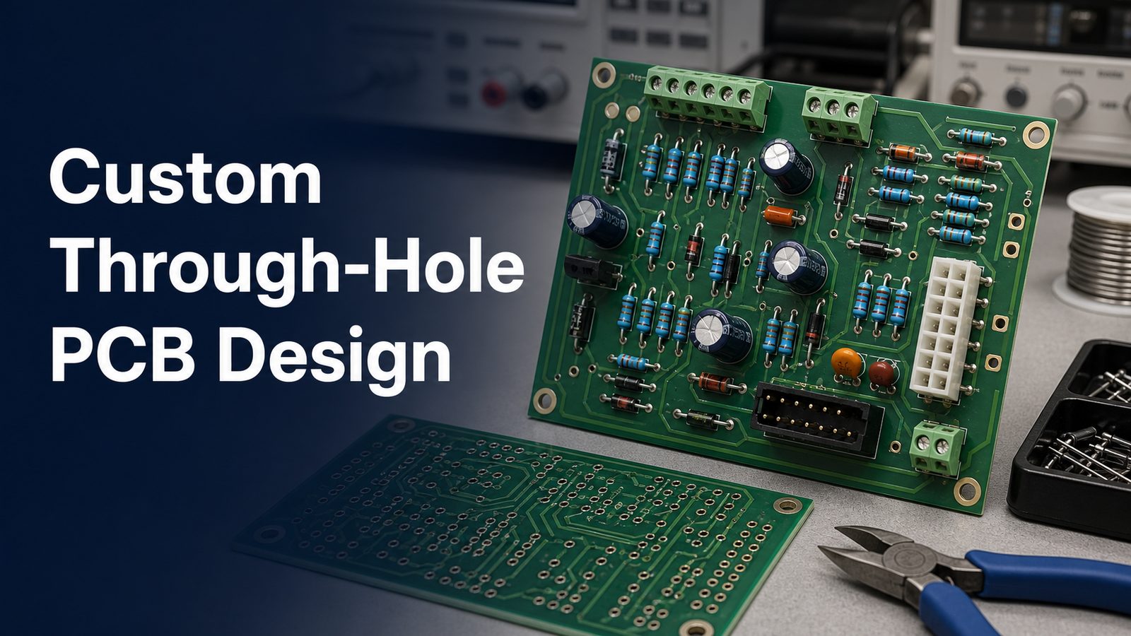
A custom through-hole PCB should be designed from the component leads outward: confirm the real lead dimensions, define finished holes and pads with the fabricator, reserve assembly access, and send complete fabrication and assembly files. The board is only ready for quotation when the manufacturer can identify every drilled hole, plated feature, component orientation, soldering method, inspection requirement, and acceptable substitution without guessing.
A useful through-hole PCB design starts with verified component leads, finished-hole requirements, and an assembly plan.
What Is a Custom Through-Hole PCB?
A custom through-hole PCB is a printed circuit board whose plated holes, pads, component footprints, mechanical outline, and assembly method are designed for a specific set of leaded components and operating constraints.
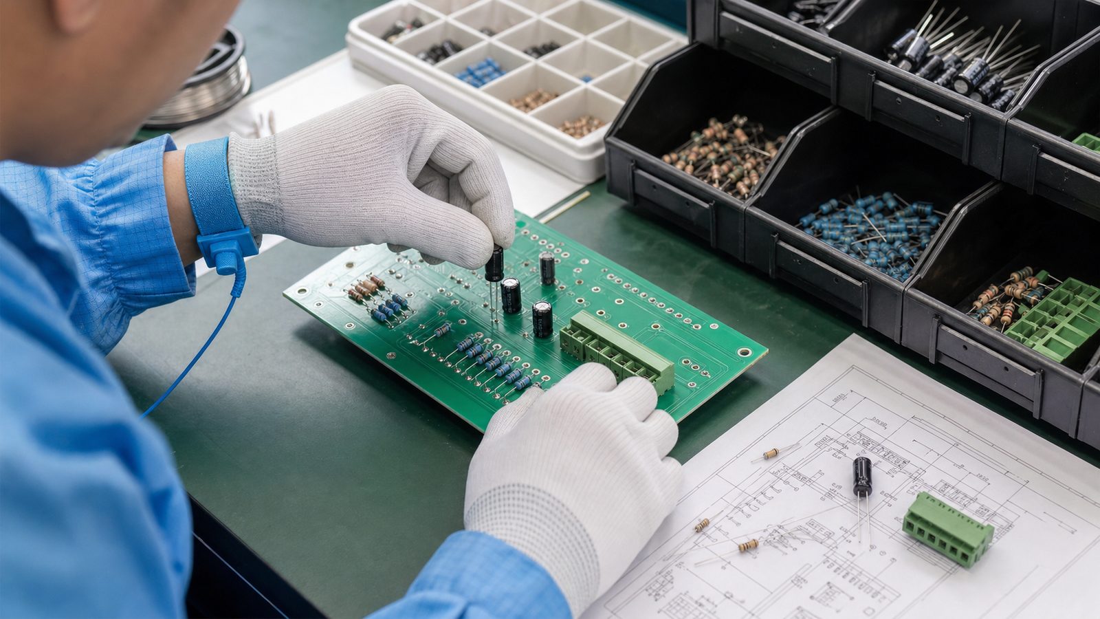
Through-hole technology (THT) places component leads through drilled holes and solders them on the opposite side. It is often selected for connectors, transformers, relays, terminal blocks, large electrolytic capacitors, switches, or other parts that need mechanical retention, serviceability, or compatibility with an existing design. A board can be entirely through-hole or use mixed technology, with SMT parts on one or both sides and selected THT parts added later.
“Custom” does not simply mean a nonstandard outline. The drill table, lead pattern, component height, copper connection, solder access, fixture needs, panel direction, and inspection criteria may all change the manufacturing route.
When Does Through-Hole Technology Make Sense?
Through-hole technology makes sense when component availability, mechanical loading, manual service, high-mass parts, or legacy compatibility matters more than maximum placement density.
Design condition
Why THT may help
What to verify
Frequently mated connector
Leads can transfer mechanical load through the board
Connector retention, board support, pad geometry, enclosure load
Large transformer, relay, or capacitor
Lead insertion provides stable placement before soldering
Mass, vibration, creepage, keepouts, adhesive or mechanical support
Prototype or field-service design
Leaded parts may be easier to probe and replace manually
Expected rework cycles and pad durability
Legacy product
Existing BOM and mechanical interfaces can be retained
Dense SMT circuitry can coexist with mechanically loaded THT parts
Process order, bottom-side clearances, soldering method, fixture access
THT is not automatically more reliable in every design. Reliability depends on the complete interconnect system: component construction, hole and pad design, laminate, copper plating, solder process, mechanical support, cleanliness, inspection, and operating environment.
How Should You Build a Through-Hole Footprint?
A through-hole footprint should be built from the current component drawing, not from a nominal package name or an unverified library symbol.
Check the lead count, pitch, lead cross-section, body size, standoff, insertion side, pin-one convention, polarization, mating direction, tolerance, and any locating or retention features. For rectangular or tab-shaped leads, the diagonal and orientation may control the required hole more than the nominal width.
Record the component manufacturer and exact orderable part number.
Use the latest mechanical drawing and note its revision.
Separate electrical leads from tooling, locating, or non-plated mounting holes.
Show polarity and pin-one marks on assembly documentation and silkscreen where space permits.
Check the courtyard against neighboring parts, insertion tools, test probes, and enclosure walls.
Confirm whether the part must sit flush, use a controlled standoff, or receive extra mechanical support.
A library footprint can be a starting point, but the released footprint should be traceable to a controlled component drawing. This is especially important for connectors and electromechanical parts whose similar product names may hide different pin spacing or retention posts.
How Do You Specify Finished Holes and Pads?
Specify the required finished-hole size and let the PCB fabricator account for its validated drilling and plating process; do not assume the drill tool equals the finished plated hole.
The required clearance depends on the maximum lead envelope, lead shape, component tolerance, insertion method, board fabrication tolerance, plating allowance, and assembly process. The correct value is therefore a design decision to confirm with both the component drawing and the selected manufacturer rather than a universal number copied from another board.
Feature
Design input
Manufacturing question
Finished plated hole
Maximum lead envelope plus validated insertion clearance
What finished-hole tolerance can be held for this stackup and quantity?
Pad and annular ring
Current, mechanical load, breakout risk, routing space
What minimum retained annular ring is supported after registration tolerances?
Thermal connection
Required current, heat flow, solderability
Will the copper connection cause difficult heating or insufficient solder fill?
Non-plated hole
Fastener, locating post, tooling, isolation
Is it clearly separated from plated drill data and copper clearances?
Slot or unusual lead
Tab dimensions and orientation
Is the slot plated, routable, and compatible with the assembly process?
Large copper planes around a THT pad can draw heat away during soldering. Thermal-relief geometry may improve solderability, but it must still meet current and mechanical requirements. Ask the fabricator and assembler to review the actual copper connection instead of applying one default rule to power terminals, signal pins, and structural leads.
What Layout Details Affect Through-Hole Assembly?
Through-hole layout must reserve physical access for insertion, lead trimming, soldering, inspection, rework, and any fixture that supports the board.
Keep polarized parts consistently oriented where practical. Leave enough space to read assembly markings and to reach solder joints without damaging adjacent components. Tall or heavy parts may need spacing from board edges and vibration-sensitive areas. Connectors must be checked in the mated condition, not just as an isolated footprint.
Insertion access, component orientation, lead retention, and fixture clearance should be reviewed before layout release.
For mixed-technology boards, review the entire process sequence. Bottom-side SMT components can interfere with wave pallets or selective-solder nozzles. A component that is easy to place by hand may still block automated soldering or inspection. If prototype and production quantities will use different soldering methods, design for both routes or document the intended change.
Which Soldering Method Should You Plan For?
Choose hand soldering, wave soldering, or selective soldering according to volume, component distribution, thermal mass, bottom-side obstructions, repeatability needs, and fixture cost.
Hand soldering suits prototypes, repairs, low volumes, and joints that need individual access, but workmanship consistency and cycle time require control.
Wave soldering can process many accessible THT joints efficiently when the underside layout, component orientation, masking, and pallet strategy support the process.
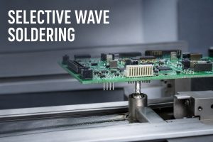
Selective soldering targets defined joints or regions and can suit mixed-technology boards where a full solder wave would contact protected areas.
The short comparison below shows the practical difference between wave and selective soldering. It belongs here because the decision directly changes layout clearances, fixtures, process time, and RFQ assumptions.
Wave soldering and selective soldering require different access, masking, and fixture decisions.
When the assembly route is not yet fixed, ask for a DFM review from the intended through-hole assembly service before freezing the bottom-side layout.
What Quality Checks Matter for a Custom Through-Hole PCB?
Quality checks should verify the bare board, component installation, solder joints, cleanliness, electrical function, and any mechanical load that the assembly must carry.
Bare-board review can include drill and plating conformity, continuity and isolation testing, hole position, annular ring, board dimensions, and surface condition. Assembly inspection should check correct components, orientation, seating, lead condition, solder coverage, bridges, void-related concerns where visible or otherwise inspectable, flux residues, and damage from handling or rework.
Inspection criteria should match the product class, drawing requirements, acceptance standard, and actual assembly process.
Do not write “IPC Class 2” or “Class 3” on an RFQ without identifying the applicable acceptance document, revision, product requirements, exceptions, and evidence expected from the supplier. If a connector carries repeated mechanical load, a functional or mechanical test may be more informative than appearance alone.
What Causes Common Through-Hole PCB Problems?
Most through-hole problems can be traced to an incorrect footprint, poorly defined hole or copper connection, unstable component retention, unsuitable solder access, uncontrolled thermal demand, or incomplete work instructions.
Observed problem
Possible design or process cause
Review action
Part will not insert consistently
Lead envelope, hole tolerance, pitch, slot orientation, or bent leads
Compare the physical part, drawing, footprint, and finished-hole data
Weak or inconsistent solder joint
Thermal imbalance, contamination, access, process window, or geometry
Review copper connections, materials, cleaning, profile, and acceptance criteria
Component lifts or tilts
Poor retention, uneven leads, fixture limits, or solder forces
Define seating, lead forming, retention, and fixture method
Pad or barrel damage during rework
Excess heat, force, dwell time, or repeated repair cycles
Define approved rework method and evaluate repairability during design
Connector fails mechanically
Board flex, enclosure load, inadequate support, or incorrect footprint
Review the complete mated mechanical system and load path
What Files Are Needed for an Accurate RFQ?
An accurate RFQ needs enough controlled data for fabrication, procurement, assembly, inspection, and acceptance without relying on assumptions.
Gerber or ODB++ fabrication data with a clearly identified revision.
NC drill files that distinguish plated and non-plated holes, plus slot definitions.
Fabrication drawing with board outline, stackup expectations, material, copper, finish, thickness, tolerances, and notes.
BOM with manufacturer part numbers, approved alternates, quantities, and do-not-fit status.
Assembly drawings for each populated side, including polarity and reference designators.
Centroid data for SMT portions of mixed-technology boards.
Special instructions for lead forming, insertion depth, standoff, clinching, adhesive, hardware, conformal coating, cleaning, or masking.
Inspection and test requirements, including fixtures, firmware, test limits, and acceptance records.
Prototype and forecast quantities, packaging needs, and any component consignment plan.
For early builds, a prototype PCB assembly run can confirm footprint fit, insertion access, soldering behavior, and test coverage before production tooling is finalized. If schedule is critical, compare the files and approvals needed for a quick-turn PCB assembly route rather than asking only for the shortest calendar lead time.
Custom Through-Hole PCB Pre-Release Checklist
A design is ready to release when the electrical, mechanical, fabrication, assembly, and inspection data agree with one another.
Match every footprint to the current component drawing and exact orderable part.
Confirm maximum lead dimensions, pitch, orientation, and retention features.
Define inspection, electrical test, functional test, cleanliness, and acceptance evidence.
Run DFM and assembly review before ordering production quantities.
Validate the prototype with the actual enclosure, cables, mating connectors, firmware, and test fixture.
Frequently Asked Questions
Is a through-hole PCB the same as a plated-through-hole PCB?
Not necessarily. “Through-hole PCB” often describes a board assembled with leaded components, while “plated through-hole” describes a hole with conductive plating connecting pads or copper layers. A board may contain plated through-holes as component holes or vias even when most components are surface mounted.
Can a custom board use both SMT and through-hole components?
Yes. Mixed-technology assemblies are common when dense SMT circuitry must coexist with connectors, relays, transformers, or other leaded parts. The layout must account for process order, bottom-side SMT parts, wave pallets or selective-solder access, inspection, and rework.
How much clearance should a lead have inside a finished hole?
There is no single clearance that fits every component and process. Use the maximum lead envelope, lead shape, insertion method, component tolerance, finished-hole tolerance, plating process, and assembly capability. Confirm the final value with the component drawing and manufacturer before release.
Should the PCB drawing specify drill size or finished-hole size?
The design documentation should clearly communicate the required finished feature and tolerance. The fabricator normally selects a process drill that accounts for plating and its controlled manufacturing route. Ambiguous drill notes can lead to incorrect assumptions, so align the drill files and fabrication drawing.
Are thermal reliefs always required on through-hole pads?
No. Thermal reliefs can improve solderability when a pad connects to a large copper area, but high-current, heat-transfer, or mechanical requirements may call for a different connection. Review electrical and thermal needs together with the solder process.
When is selective soldering better than wave soldering?
Selective soldering is useful when only defined THT joints can contact solder or when bottom-side SMT parts and sensitive areas prevent full wave exposure. Wave soldering can be efficient for layouts designed around broader underside access. Volume, fixture cost, spacing, and thermal demand also affect the choice.
What should be included in a through-hole assembly drawing?
Show component locations, reference designators, insertion side, polarity, pin one, orientation, do-not-fit parts, special seating or standoff requirements, hardware, lead forming, and revision. Add separate controlled instructions when soldering, masking, cleaning, coating, or test requirements need more detail.
How can connector solder joints be protected from mechanical stress?
Design the load path across the connector, board, mounting hardware, enclosure, and cable. Board supports, retention features, fasteners, strain relief, adequate pad and hole design, and controlled mating forces may all matter. Do not expect solder joints alone to absorb repeated external load.
What should be tested on a first prototype?
Verify component fit, polarity, insertion and solder access, electrical continuity, programmed function, connector mating, enclosure fit, temperature behavior, mechanical loads, test-point access, and rework feasibility. Record every change against the controlled design revision before production release.
How do I reduce quotation delays?
Send synchronized fabrication data, drill files, BOM, assembly drawings, test requirements, quantities, and revision identifiers. Flag alternate parts and special processes clearly. A concise question list for unresolved items is better than leaving the supplier to infer missing requirements.
Final Design Decision
A custom through-hole PCB succeeds when the component drawing, finished-hole definition, copper connection, assembly access, soldering route, inspection plan, and RFQ package describe the same product. Resolve those interfaces before production, not during component insertion.
If you are preparing a through-hole or mixed-technology PCB for prototype or production, send the engineering files, BOM, expected quantities, soldering constraints, and test requirements to sales@bestpcbs.com for DFM review and quotation.
Electronic product development testing is a staged system for proving that a device meets its requirements, survives its intended environment, and can be manufactured repeatedly. A useful plan connects requirements, schematic and PCB reviews, prototype bring-up, EVT, DVT, PVT, compliance work, and production test data instead of treating testing as one final event.
This guide is a practical companion to our Electronic Product Design & Test overview. It focuses on the evidence and exit criteria that hardware teams should establish before releasing a PCB-based product to volume manufacturing.
What Should an Electronic Product Testing Checklist Prove?
A complete checklist should prove five things: the product does the intended job, the design has acceptable margin, foreseeable failure modes are controlled, regulatory work is planned, and the factory can build and test the product consistently.
Start with traceable requirements rather than a list of instruments. Each important requirement needs a verification method, acceptance limit, responsible owner, sample stage, and record location. “The unit powers on” is not an adequate criterion. “The unit starts from the specified input range, reaches its operating state within the defined time, and reports no diagnostic fault” is testable.
Evidence area
Question answered
Typical record
Functional
Does every required function work across normal and boundary conditions?
Requirement-to-test matrix and test report
Electrical
Are rails, interfaces, timing, current, and protection behavior within limits?
Waveforms, measurements, and fault-injection results
Mechanical and thermal
Does the assembled product fit, cool, and withstand expected loads?
Fit review, thermal map, and environmental results
Manufacturing
Can PCB fabrication, assembly, programming, inspection, and rework be repeated?
DFM/DFT review, work instructions, pilot build data
Compliance
Is the design prepared for the standards and market requirements that apply?
Compliance plan and accredited-lab reports where required
Production quality
Can each unit be screened with stable limits and traceable results?
Fixture validation, limits file, serial-number test log
How Do Requirements Become Verifiable Test Cases?
Requirements become verifiable when each statement has one meaning, a measurable limit, a defined condition, and an objective pass/fail method. Ambiguous words such as “fast,” “low power,” or “high reliability” should be replaced by product-specific limits.
Define the use case. Record users, loads, duty cycle, interfaces, installation, abuse cases, and service expectations.
Set operating boundaries. Specify input range, temperature, humidity, vibration, communication conditions, and expected lifetime assumptions.
Identify safety and compliance constraints. The target market and product category determine which standards need professional review.
Write acceptance criteria. Include units, tolerances, test duration, setup, firmware revision, and sample quantity.
Build a traceability matrix. Link each requirement to design evidence, one or more tests, results, and corrective actions.
Traceability prevents a common release problem: many tests are completed, but nobody can show whether every important requirement was actually covered. It also makes change review faster because an engineering change can be mapped to affected requirements and regression tests.
Which Design Reviews Should Happen Before the First Prototype?
Before prototype fabrication, review the architecture, schematic, PCB layout, BOM, mechanical interfaces, firmware hooks, manufacturability, and test access. Problems found in files are normally easier to correct than problems found after boards, stencils, fixtures, or tooling exist.
Architecture: power budget, interface partitioning, protection strategy, diagnostic coverage, and upgrade path.
DFT: test pads, ground references, boundary access, programming connector, fixture datum points, safe test modes, and diagnostic firmware.
Use the manufacturer’s real process capability for the final review. Generic design rules are a starting point; stack-up, materials, copper, tolerances, assembly equipment, inspection access, and fixture strategy must match the chosen production route. Best Technology’s PCB capability information, PCB assembly service, and PCB design tools can support this handoff.
What Are EVT, DVT, and PVT in Hardware Validation?
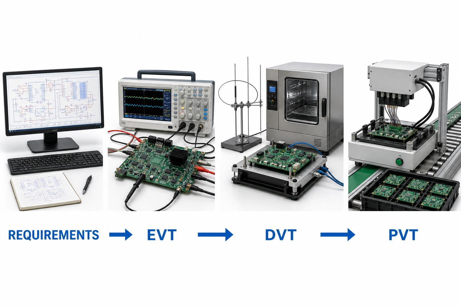
EVT, DVT, and PVT are progressive validation gates: EVT proves the engineering concept, DVT proves the finished design against requirements, and PVT proves the production process. The exact names and sample quantities vary by company, but the gate logic should remain clear.
Each stage should close a different risk: engineering function, design compliance, then production repeatability.
Gate
Main question
Typical activities
Exit evidence
Prototype / bring-up
Can the core circuits and firmware operate?
Rail checks, current-limited power-up, interface debug, first functional tests
Bring-up log and prioritized issue list
EVT
Does the engineering design meet core functional and performance targets?
Boundary tests, thermal measurements, signal checks, early EMC checks, design revisions
Core requirements passed and high-risk design issues closed
DVT
Does the production-intent design meet the full requirement set?
Mechanical, environmental, reliability, safety, EMC/RF, usability, and regression testing
Design verification report and controlled release candidate
PVT
Can the intended line build and test the controlled design repeatedly?
Pilot build, work-instruction trial, fixture validation, operator training, yield analysis
Released process, stable test limits, traceability, and approved deviations
Mass production
Does ongoing output remain under control?
Incoming, in-process, functional, final, reliability-monitoring, and change-control activities
Production data, corrective actions, and controlled change history
Do not advance a stage because a calendar date arrived. Advance when the agreed evidence is complete, critical failures are understood, retesting is finished, and open risks are formally accepted by the responsible team.
How Should Prototype Bring-Up and EVT Be Run?
Prototype bring-up and EVT should move from safe, observable checks to integrated operation. The goal is not to demonstrate one successful unit; it is to understand the design margin, failure behavior, and revisions needed before design verification.
Confirm board revision, assembly drawing, BOM substitutions, and inspection results.
Check resistance to ground on key rails before applying power.
Use current-limited supplies and verify power sequencing, reset, clocks, and programming access.
Load controlled firmware and record the hardware, firmware, equipment, and test-script versions.
Test interfaces and core functions individually before full-system operation.
Measure current, ripple, timing, thermal behavior, signal quality, and fault response at nominal and boundary conditions.
Run early EMC and thermal pre-checks while layout changes are still practical.
Convert every failure into a reproducible condition, suspected mechanism, corrective action, and regression test.
Preserve failed units when they provide useful evidence. Replacing a component until the prototype works may restore operation but can erase the root cause. Photograph the board, capture waveforms, record configuration, and compare the failure with a known-good sample before rework.
What Must DVT Prove Before the Design Is Frozen?
DVT must show that the production-intent product satisfies its complete requirement set under realistic operating, environmental, mechanical, and compliance-related conditions. It should use controlled hardware, firmware, enclosure, cable, labeling, and accessories.
The DVT plan commonly covers functional regression, power modes, thermal steady state and cycling, input extremes, ESD and EMC pre-compliance, vibration or drop where relevant, ingress or humidity where relevant, connector endurance, abnormal operation, firmware recovery, and long-duration operation. Product category and destination market determine the actual safety, EMC, radio, environmental, or industry standards; confirm them with a qualified compliance professional or test laboratory.
Define sample allocation before testing. Some tests are destructive or can age the samples, so the same unit should not automatically be reused for unrelated validation. Record serial number, build history, firmware, calibration status, test order, deviations, failures, repairs, and retest outcome. A passing summary without configuration data is weak evidence because it cannot reliably support a later investigation.
How Do DFM and DFT Reduce Production Risk?
DFM reduces variation in fabrication and assembly, while DFT makes faults observable and testable. Together they turn a working prototype into a product that can be built, inspected, programmed, and screened without depending on one expert technician.
For PCB assembly, DFM should review footprints, component orientation, paste apertures, thermal balance, bottom-terminated parts, BGA inspection needs, hand-inserted parts, depanelization stress, cleaning requirements, and rework clearance. Inspection planning should match the fault type: AOI can detect many visible placement and solder defects, while X-ray is useful for hidden joints. Neither confirms product function.
DFT should define accessible power, ground, communication, programming, and diagnostic points; safe fixture contact areas; mechanical datums; test modes; unique identifiers; and useful failure codes. If a fixture needs access from both sides, presses on fragile parts, or depends on manually probing tiny pads, redesign may be cheaper than accepting slow and variable testing.
How Should a Production Functional Test Fixture Be Validated?
A production functional test fixture should be validated as a measurement system, not merely confirmed to turn on. It needs repeatable contact, controlled stimulus, protected interfaces, known limits, version control, calibration or reference checks, and a clear reaction plan for failures.
A repeatable fixture combines mechanical location, electrical contact, controlled software, pass/fail limits, and result traceability.
Electrical protection: prevent reverse connection, overcurrent, unsafe discharge, and damage from an already-faulty unit.
Reference strategy: maintain known-good and known-fault samples or simulation methods to check detection behavior.
Software control: lock script, firmware, drivers, limits, and instrument configuration to released versions.
Repeatability: run repeated measurements across operators, fixtures, and time; investigate results near limits.
Traceability: store unit ID, date, station, fixture, software version, measured values, result, and failure code.
Pass/fail limits should come from product requirements and validated process behavior, not from copying one golden unit’s exact measurements. A limit that is too wide permits escapes; a limit that is too narrow creates false failures and unnecessary rework.
What Should PVT and the Pilot Build Measure?
PVT should measure whether the released design, materials, line, tooling, work instructions, inspection plan, and test system produce consistent results under normal manufacturing conditions. It is a production experiment, not an engineering showcase.
Use production-intent suppliers, parts, PCB panels, assembly equipment, operators, firmware-loading method, fixtures, labels, packaging, and data systems. Track first-pass yield by process step, defect and failure-code Pareto, cycle time, repair rate, no-fault-found rate, fixture downtime, component substitutions, deviations, and traceability completeness.
Review failures by mechanism rather than only by count. A small number of repeated contact failures may indicate a weak fixture. Random resets may point to electrical margin, programming, or firmware state. Solder defects concentrated on one package may require footprint, stencil, thermal-profile, handling, or component-finish review. Corrective action should update the controlled design or process documents and trigger appropriate regression testing.
How Do You Control Failures, Changes, and Test Data?
Failures and changes should be managed through a closed loop that preserves evidence, controls revisions, and proves the correction. Without this discipline, teams repeatedly fix symptoms, mix configurations, or release changes that invalidate earlier test results.
Contain affected samples, lots, files, and test stations.
Describe the failure condition and reproduce it where possible.
Separate symptom, physical mechanism, and root cause.
Implement corrective action through controlled engineering or process change.
Verify the fix on affected tests and run regression tests for nearby risks.
Update drawings, BOM, Gerbers, firmware, work instructions, fixture files, limits, and revision history together.
Monitor later builds to confirm the correction remains effective.
Useful test data should support decisions. Store measured values when they help detect drift, not only pass/fail. Trend parameters such as current, calibration values, RF power, temperature rise, or test duration when they are linked to product or process risk. Protect access and retention according to customer, product, and regulatory needs.
What Files Should Be Released to the Manufacturing Partner?
The manufacturing package should define exactly what to build, how to inspect and test it, and how to report deviations. Send controlled revisions and one release index so the factory does not have to infer which files belong together.
Gerber or approved fabrication data, drill data, stack-up, material, finish, copper, impedance, panel, and special notes.
BOM with manufacturer part numbers, approved alternates, do-not-substitute rules, and lifecycle concerns.
Pick-and-place data, assembly drawings, polarity and orientation notes, stencil requirements, and mechanical drawings.
Inspection criteria, X-ray requirements, workmanship class or customer criteria where contractually defined.
Functional test specification, setup, sequence, limits, fixture interface, diagnostic codes, and example results.
Label, serial number, traceability, packaging, moisture, ESD, and shipping requirements.
Approved deviation process, engineering contacts, and change-notification requirements.
For a manufacturing review or quotation, provide the maturity level and unresolved risks as well as the files. Best Technology can review PCB fabrication, component sourcing, PCBA assembly, inspection, and test needs as one handoff. Available equipment and test information can be reviewed on the quality and test equipment page.
Electronic Product Development Testing FAQs
What is the difference between verification and validation?
Verification checks whether the design meets specified requirements; validation checks whether the resulting product meets the intended user need and use environment. A voltage measurement can verify an electrical requirement, while a field-representative use test can help validate that the complete product solves the intended problem.
Why can a prototype work while production units fail?
A prototype may receive hand assembly, expert debugging, selected parts, and flexible rework. Production introduces normal variation in components, soldering, handling, operators, fixtures, and environment. Marginal footprints, missing test access, weak electrical margin, or uncontrolled substitutions often appear only when repeatability is required.
What are practical EVT exit criteria?
EVT can exit when core functions and interfaces meet agreed targets, high-risk electrical and thermal behavior has been measured, critical defects have corrective actions, remaining risks are documented, and the design is mature enough for production-intent DVT samples. The criteria should be agreed before the build.
How many samples are needed for DVT?
There is no universal DVT sample count. It depends on product risk, test destructiveness, configuration variants, reliability goals, compliance plans, and confidence required. Create a sample allocation matrix with the responsible engineer and relevant test laboratories rather than copying a generic number.
When should EMC testing begin?
EMC risk review should begin during architecture and PCB layout. Bench pre-compliance checks during EVT can reveal grounding, filtering, cable, enclosure, and routing problems while changes remain manageable. Formal testing should use a stable production-intent configuration appropriate to the target market and product category.
What is a golden sample?
A golden sample is a controlled reference unit with known configuration and measured behavior. It can help check fixtures and compare failures, but it should not be the sole source of pass/fail limits. Requirements, tolerances, measurement uncertainty, and validated production data should determine limits.
Do AOI and X-ray replace functional testing?
No. AOI checks visible assembly conditions, and X-ray helps inspect hidden joints and structures. They can find manufacturing defects but cannot prove that firmware, interfaces, sensors, power behavior, or the full product function meets requirements. Inspection and functional testing cover different fault classes.
What is test coverage in production?
Test coverage describes how well the test strategy can detect defined faults or verify requirements. It is not simply the number of test steps. Teams should map likely failure modes and critical functions to inspection, electrical test, programming checks, functional tests, and sampling-based reliability activities.
Should firmware be tested separately from hardware?
Firmware needs unit and integration testing, but hardware-in-the-loop and complete-product tests are also necessary. Timing, power transitions, sensors, communication, memory, recovery, provisioning, and fault behavior emerge from the interaction between firmware, electronics, and the production configuration.
How often should production test limits be reviewed?
Review limits after design or process changes, fixture maintenance, instrument changes, abnormal yield shifts, field failures, or evidence of measurement drift. Routine trend review can identify problems before pass/fail rates change. Any update should be authorized, versioned, validated, and linked to the affected stations.
What information is needed for an electronic product testing quote?
Provide product function, target market, design maturity, schematic, PCB files, BOM, firmware needs, enclosure data, expected volume, known risks, required tests, acceptance limits, and desired deliverables. If requirements are incomplete, identify them clearly so the supplier can scope engineering work rather than assuming coverage.
Can one supplier handle design, PCB, assembly, and testing?
Yes, an integrated supplier can coordinate design feedback, PCB fabrication, component sourcing, assembly, prototypes, fixtures, and production testing. Buyers should still confirm responsibilities, file ownership, change control, test evidence, capability, and which compliance activities require an external accredited laboratory.
Build the Test Strategy Before You Build the Fixture
The strongest electronic product development testing plan begins with requirements and risk, then adds the right reviews, prototypes, validation stages, fixtures, data, and release evidence. Planning DFM and DFT early reduces avoidable redesign, while disciplined EVT, DVT, and PVT gates keep engineering success separate from production readiness.
If you are sourcing electronic product design support, PCB prototyping, PCB assembly, OEM/ODM development, sample validation, or production testing, contact the Best Technology engineering team at sales@bestpcbs.com for a technical review and quotation.
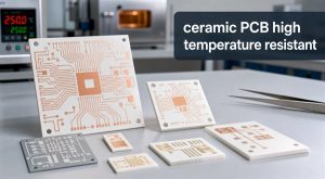
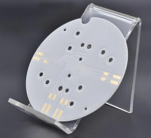
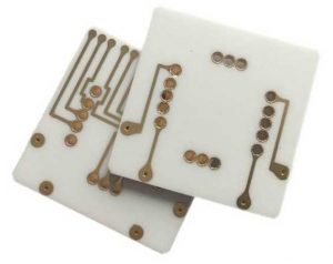
ceramic pcb prototype production is the controlled sample-building stage used to verify a ceramic circuit design before volume manufacturing. It helps engineers confirm substrate choice, copper pattern, thermal path, tolerances, assembly risk, and test requirements before committing to production tooling or a larger order.
For buyers and hardware teams, a ceramic PCB prototype is not just a small quantity of boards. It is a practical engineering checkpoint for high-power LEDs, power modules, sensors, RF designs, automotive electronics, medical devices, and other circuits where heat, dimensional stability, insulation, or reliability can decide whether the final product works.
What Is Ceramic PCB Prototype Production?
Ceramic PCB prototype production is the first manufacturing run of a ceramic circuit board design, usually built to validate the material, copper layout, process route, inspection plan, and assembly compatibility. The goal is to find manufacturability issues while the design can still be corrected without large production losses.
Unlike a standard FR4 prototype, a ceramic prototype depends heavily on substrate behavior, metallization method, firing or bonding process, conductor adhesion, surface flatness, and thermal expansion matching. A good prototype order should therefore answer both electrical and manufacturing questions, not only confirm that the Gerber files can be plotted.
For a new project, the prototype stage often confirms whether ceramic PCB technology is the right direction, or whether an alternative such as FR4 PCB or metal-core PCB is enough for the thermal and cost target.
Why Is Ceramic PCB Prototyping Different from FR4 PCB Prototyping?
Ceramic PCB prototyping is different because the substrate is rigid, hard, thermally conductive, and much less forgiving than glass-reinforced epoxy laminate. The process needs more attention to ceramic material selection, copper bonding, drilling or laser processing, dimensional tolerance, and thermal cycling behavior.
Prototype factor
FR4 PCB prototype
Ceramic PCB prototype
Base material
Glass epoxy laminate
Al2O3, AlN, BeO alternatives, LTCC, HTCC, or other ceramic substrates
Main design concern
Signal routing, layer stack, cost, and standard fabrication limits
Thermal path, ceramic thickness, copper adhesion, CTE match, and process route
Mechanical behavior
Can flex slightly before fracture
Brittle and requires careful handling, panel design, and fixture planning
Prototype review focus
DFM, impedance, hole quality, solder mask, assembly fit
Metallization quality, substrate flatness, thermal design, edge quality, and inspection plan
This difference affects the RFQ stage. A supplier should review not only the Gerber data, but also the ceramic material, copper thickness, board outline, via structure, tolerance needs, component heat load, and whether the prototype must support later mass production approval.
Which Ceramic PCB Material Should You Choose for a Prototype?
The best ceramic prototype material depends on thermal conductivity, insulation requirement, mechanical strength, cost target, and the final application environment. Al2O3 is commonly chosen for cost-effective ceramic prototypes, while AlN is often selected when higher thermal conductivity is required.
Material or technology
Why it is used in prototypes
Typical review point
Al2O3 ceramic
Balanced cost, insulation, mechanical stability, and mature processing
Check whether thermal performance is enough for the heat load
AlN ceramic
Higher thermal conductivity for power and LED designs
Confirm cost, availability, and metallization compatibility
Thick film ceramic
Useful for printed conductor, resistor, and hybrid circuit structures
Review conductor geometry and fired pattern tolerance
Thin film ceramic
Used where fine lines, stable circuits, or precise patterns are needed
Confirm line width, adhesion, finish, and application fit
DPC, DCB, or related structures
Selected when copper thickness, thermal path, or power handling drives the design
Match the process route to copper thickness and reliability needs
If the project is still early, ask the manufacturer to compare available ceramic options before confirming the prototype route. EBest Circuit supports ceramic PCB categories such as thick film ceramic PCB, thin film ceramic PCB, DPC ceramic PCB, and DCB ceramic PCB, so the prototype can be planned around the final production requirement instead of treated as an isolated sample.
What Is the Ceramic PCB Manufacturing Process?
The ceramic PCB manufacturing process usually starts with design review and material selection, then moves through substrate preparation, metallization, patterning, firing or bonding, surface finish, profiling, inspection, testing, and packing. The exact route depends on whether the project uses thick film, thin film, DPC, DCB, LTCC, HTCC, or another ceramic process.
Material preparation: Select Al2O3, AlN, or another ceramic substrate and confirm thickness, size, flatness, and handling needs.
Metallization and patterning: Build the conductive layer using the selected process route, then define circuit features according to the design.
Thermal or bonding process: Fire, sinter, plate, bond, or otherwise stabilize the conductor system depending on the technology.
Finishing and profiling: Apply the required surface finish, cut the outline, and prepare the board for inspection or assembly.
Inspection and test: Review dimensions, conductor quality, insulation, open/short status, surface quality, and packaging condition.
A prototype should be reviewed as a process sample. If the prototype later moves into production, the same data package, material choice, and inspection criteria should be stable enough to repeat.
How Do Thick Film, Thin Film, DPC and DCB Affect Prototype Production?
Different ceramic PCB process routes affect prototype cost, minimum features, copper thickness, thermal performance, and sample lead time. Choosing the process too late can force the engineering team to redesign pads, traces, vias, or thermal areas after the first prototype.
Thick film ceramic PCB is often used for hybrid circuits and printed conductor structures. It can be practical for prototypes where fired pastes, resistive elements, or ceramic-based circuit patterns are part of the design.
Thin film ceramic PCB is better suited for finer features and stable circuit requirements. It is often reviewed for sensor, microwave, medical, and precision electronic applications where conductor geometry matters.
DPC and DCB ceramic PCB routes are more closely tied to power electronics and heat transfer. For these prototypes, copper thickness, adhesion, thermal cycling, and substrate-to-copper reliability need early review.
What Files Are Needed for a Ceramic PCB Prototype Quote?
A ceramic PCB prototype quote is more accurate when the supplier receives a complete technical package, not just a screenshot or partial Gerber export. Missing tolerances, material notes, and assembly requirements can cause delays or a quote that does not match the real production risk.
Gerber files and drill data
Board outline drawing with critical dimensions
Ceramic material preference, such as Al2O3 or AlN
Substrate thickness and copper thickness requirement
Surface finish requirement
Panelization or single-piece delivery preference
Quantity for prototype and expected production volume
Assembly files if the prototype needs PCBA service
Thermal, electrical, or reliability test requirements
Application notes, especially for high-power, high-temperature, LED, sensor, or RF use
When a buyer provides both the prototype quantity and the expected mass production target, the manufacturer can recommend a route that avoids sample-only shortcuts that may not scale.
What Should You Check Before Moving from Prototype to Production?
Before moving from ceramic prototype to production, check whether the prototype truly validates the final design, process, material, and inspection standard. A board that passes a simple electrical test may still need thermal, mechanical, and assembly review before mass production.
Confirm the ceramic material and thickness match the final thermal design.
Check conductor adhesion, line quality, edge quality, and surface finish.
Review substrate flatness and dimensional tolerance against assembly needs.
Test open/short status, insulation resistance, and critical electrical paths.
Review solderability or bonding compatibility if components will be mounted.
Record any design changes before approving the production file set.
Ask whether the same process route will be used for the production batch.
The cleanest transition happens when the prototype report, customer feedback, corrected files, and final production requirements are all connected before the next purchase order.
What Problems Can Delay Ceramic PCB Prototype Production?
Ceramic PCB prototype production is often delayed by incomplete files, unclear material selection, unrealistic tolerances, process-route mismatch, missing assembly data, or late changes to the thermal design. These problems are easier to fix before production starts than after substrates and tooling have been prepared.
Delay cause
Why it matters
How to prevent it
Unclear ceramic material
Al2O3, AlN, and other ceramics change cost and thermal behavior
Share heat load, application, and target cost before quoting
Missing tolerance drawing
Ceramic processing may need different tolerance planning than FR4
Mark critical dimensions and non-critical dimensions separately
Wrong process route
Thick film, thin film, DPC, and DCB do not fit the same designs equally
Ask the supplier to review process fit before sample build
Late assembly requirement
Pad finish, flatness, and component heat transfer may need early planning
Send BOM, placement file, and assembly notes with the RFQ
How to Choose a Ceramic PCB Prototype Manufacturer?
Choose a ceramic PCB prototype manufacturer by checking whether the supplier can review material selection, process route, DFM risk, inspection requirements, assembly needs, and future production scaling. Price matters, but the cheapest sample is not useful if the process cannot support the final product.
Good supplier questions include:
Which ceramic materials and process routes are suitable for this design?
Can the same route support prototype and mass production?
What design features may increase cost or delay?
Which tolerances should be relaxed if they are not functional?
What tests are recommended for this application?
Can assembly, inspection, and packaging be coordinated in one project flow?
EBest Circuit can support custom ceramic PCB projects from prototype review to sample production and later batch manufacturing. For projects that need assembled samples, prototype PCB fabrication can also be coordinated with PCBA review to reduce handoff risk.
FAQ
How much does a ceramic PCB prototype cost?
Ceramic PCB prototype cost depends on material, substrate thickness, copper thickness, process route, dimensions, tolerance level, quantity, surface finish, testing, and whether assembly is included. Al2O3 prototypes are often more cost-effective than higher thermal conductivity ceramic options, but the right choice should be based on the heat load and reliability target.
Can ceramic PCB prototypes be assembled?
Yes, ceramic PCB prototypes can be assembled when the pad finish, flatness, component package, soldering or bonding method, and thermal requirements are reviewed early. If assembly is needed, send the BOM, placement file, polarity notes, and any thermal interface requirements with the PCB quotation package.
Is Al2O3 or AlN better for ceramic PCB prototype production?
Al2O3 is often selected for balanced cost and mature processing, while AlN is chosen when higher thermal conductivity is required. The better option depends on the heat source, insulation requirement, mechanical design, available budget, and whether the prototype must represent a later production build.
Can one ceramic PCB prototype be used for mass production approval?
One prototype can support production approval only if it uses the same material, process route, design file set, tolerance standard, inspection method, and assembly assumptions planned for mass production. If the prototype used sample-only changes, a second verification run may be needed before release.
What tolerances matter most in ceramic PCB prototyping?
The most important tolerances are usually board outline, hole or slot position, substrate thickness, copper feature size, registration, flatness, and critical pad locations. The buyer should identify which dimensions affect assembly or function, because unnecessary tight tolerances can increase cost and delay without improving performance.
What is the difference between ceramic prototype and ceramic PCB prototype?
A ceramic prototype can refer to any trial part made from ceramic material, while a ceramic PCB prototype is a circuit board sample built on a ceramic substrate with conductive patterns for electronic use. For RFQ clarity, use ceramic PCB prototype when the part includes circuit fabrication requirements.
How Can EBest Circuit Support Ceramic PCB Prototype Production?
EBest Circuit supports ceramic PCB prototype production by helping buyers review materials, process route, manufacturability, inspection needs, and assembly requirements before moving into larger production. If you are developing a ceramic PCB for LED, power electronics, sensor, automotive, medical, or industrial electronics applications, send your files and requirements to the engineering team for a practical review and quotation at sales@bestpcbs.com.
An intercom circuit board integrates voice capture, audio processing, wired or wireless communication, power management and access-control functions. Reliable operation depends on circuit architecture, PCB layout, component quality, firmware and production testing. EBest Circuit provides custom PCB manufacturing and assembly services for door-entry systems, wireless intercoms, building communication panels and industrial talkback equipment.
Are you worried about these problems in intercom circuit board projects?
Design challenges: Poor grounding, incorrect gain settings or unsuitable antenna placement may cause noise, echo, weak audio and unstable wireless communication.
Production risks: Incomplete files, material shortages and uncontrolled impedance may delay prototypes or affect batch consistency.
Assembly difficulties: Fine-pitch parts, microphones, wireless modules and hidden solder joints require precise placement and reliable inspection.
As a one-stop PCBA service provider with more than 20 years of industry experience, EBest Circuit provides the following solutions:
Design optimization: We review audio circuits, power distribution, grounding, RF routing and antenna layout to reduce noise and communication failures.
Controlled production: We verify manufacturing files, materials, impedance and component availability before fabrication to reduce delays and redesigns.
Reliable assembly and testing: We provide SMT and THT assembly, SPI, AOI, X-ray, programming and functional testing to verify product performance.
Send your Gerber files, BOM and test requirements to EBest Circuit via sales@bestpcbs.com for a quotation.
What Is an Intercom Circuit Board?
An intercom circuit board is the electronic platform that receives, processes, transmits and reproduces voice and control signals between communication stations. It is used in analog door-entry units, digital building systems, wireless handsets, IP intercoms and industrial communication terminals.
The board connects microphones, speakers, call buttons, displays, relays, power inputs and communication interfaces. A basic intercom PCB may use analog amplifiers and switching circuits, while an advanced design can include an MCU, DSP, audio codec, wireless module, Ethernet PHY and access-control output.
The circuit architecture depends on audio quality, communication distance, network type, enclosure size, power source and operating environment.
What Functions Does an Intercom PCB Control?
An intercom PCB controls audio capture, signal processing, communication, user commands and power distribution. The exact functions depend on whether the product is analog, digital, wired, wireless or IP-based.
Common functions include:
Capturing voice through an electret or MEMS microphone
Filtering and amplifying microphone signals
Converting audio between analog and digital formats
Driving speakers, handsets or headsets
Supporting half-duplex or full-duplex communication
Processing buttons, keypads and status indicators
Controlling electric locks, relays and alarms
Managing WiFi, Bluetooth, RF, Ethernet or two-wire connections
Regulating input power into separate voltage rails
Storing firmware, addresses and operating settings
Protecting external interfaces against ESD and voltage surges
Stable performance requires these functions to operate without introducing noise, distortion or communication interference.
What Are the Main Components of an Intercom Circuit Board?
An intercom circuit board normally includes audio input, signal processing, communication, speaker output, power and protection circuits. The actual configuration depends on the system architecture and product functions.
Component
Typical Selection
Main Function
Microphone
Electret, analog MEMS or digital MEMS
Captures voice
Microphone front end
Bias circuit, low-noise amplifier and filter
Conditions weak microphone signals
Audio codec
ADC, DAC and I²S interface
Converts analog and digital audio
Processor
MCU, DSP or application SoC
Controls audio, communication and system logic
Program memory
SPI NOR, EEPROM, NAND or eMMC
Stores firmware and configuration
Working memory
Internal SRAM or external DDR
Buffers audio and processing data
Audio amplifier
Class AB or Class D
Drives the speaker or handset
Speaker interface
Filter, protection and connector
Connects and protects the speaker output
Wireless circuit
Sub-GHz, Bluetooth or WiFi module
Provides wireless communication
RF network
Matching components, RF feed and antenna
Transfers RF energy to the antenna
Wired interface
Two-wire line interface or RS-485 transceiver
Supports wired communication
Ethernet interface
PHY, magnetics and RJ45 connector
Supports IP communication
PoE circuit
PoE PD controller and DC-DC converter
Receives power through Ethernet
Access-control output
Relay, MOSFET or transistor driver
Controls locks, alarms or gates
User interface
Buttons, keypad, LEDs or display driver
Processes commands and status
Clock and reset
Crystal, oscillator and reset IC
Controls timing and startup
Power supply
Buck, boost or LDO regulator
Generates stable voltage rails
Protection circuit
Fuse, TVS, ESD and reverse-polarity protection
Protects power and external interfaces
Debug interface
SWD, JTAG, UART or USB
Supports programming and diagnostics
Connector
Terminal block, FFC or board-to-board connector
Connects external devices
A basic analog board may not require a processor, external memory or Ethernet circuit. An IP intercom with video, networking or an operating system may require a higher-performance SoC, DDR and eMMC.
The microphone front end, power supply, grounding, speaker amplifier and communication interface have the greatest influence on audio clarity and stability.
How to Read an Intercom Circuit Board Schematic and Block Diagram?
Read the functional block diagram first to understand the complete signal flow. Then use the schematic to verify how each circuit is powered, controlled and connected.
Identify the system type: Confirm whether the product is analog, digital, two-wire, wireless or IP-based.
Trace the power tree: Follow the input through the fuse, reverse-polarity protection, surge protection and voltage converters.
Follow the microphone path: Check microphone bias, input protection, filters, amplifier gain and codec input.
Review the processor section: Locate the MCU, DSP or SoC and check its clock, reset, memory, boot and programming circuits.
Trace the speaker path: Follow the signal through the codec, amplifier, output filter and speaker connector.
Inspect communication circuits: Review RF, Ethernet, RS-485 or two-wire interfaces separately.
Check lock-control outputs: Confirm the relay or MOSFET driver, flyback protection and load connection.
Compare with the PCB layout: Confirm that audio, RF, switching-power and speaker-current paths are separated.
Check test access: Locate power, reset, programming, audio and communication test points.
This method helps identify incorrect voltages, excessive gain, missing protection and potential noise paths before production.
How Should a Wireless Intercom PCB Be Designed?
A wireless intercom PCB must balance RF performance, audio quality, power stability and mechanical constraints. These areas should be planned together because antenna placement, speaker current and switching noise can directly affect voice clarity and communication range.
Step 1: Define the product requirements. Confirm the wireless protocol, operating frequency, communication range, microphone type, speaker power, input voltage, enclosure size and duplex mode. These requirements determine the processor, RF solution, audio circuit and PCB layer count.
Step 2: Choose the wireless solution. A pre-certified wireless module can shorten development time and reduce RF certification risk. A discrete RF SoC provides more control over board size, antenna design and production cost but requires stronger RF design and testing capability.
Step 3: Plan the power system. Separate the power needs of the processor, RF circuit, microphone front end and speaker amplifier. Use suitable converters, LDOs, decoupling capacitors and bulk capacitance to prevent RF transmission or high speaker volume from causing voltage drops and resets.
Step 4: Select the PCB layer structure. A four-layer PCB is suitable for most wireless intercom products. One internal layer should provide a continuous ground plane, while another supports power distribution and low-speed signals. More layers may be required for external memory, Ethernet or dense routing.
Step 5: Divide the board into functional areas. Separate the microphone circuit, processor, RF section, power converter and speaker amplifier. Keep low-level audio circuits away from switching nodes, inductors, crystals and high-current speaker traces.
Step 6: Position the antenna carefully. Place the antenna near the PCB edge and follow the supplier’s keep-out requirements. Batteries, speakers, shields, cables, copper and metal fasteners should remain outside the antenna area because they can reduce range and change antenna tuning.
Step 7: Route the RF path correctly. Keep the RF feed short and route it as a controlled 50 Ω transmission line. Maintain a continuous ground reference, avoid unnecessary vias and place the matching network close to the antenna or RF output.
Step 8: Protect the microphone signal. Place microphone biasing, filtering and preamplification close to the microphone. Keep analog audio routes short and away from RF feeds, clocks, Class D outputs and switching regulators.
Step 9: Control speaker current paths. Use short, wide traces for the amplifier supply, ground and speaker output. High-current return paths should not cross the microphone, codec or RF sections.
Step 10: Maintain a clean ground reference. Use a continuous ground plane instead of unnecessary ground splits. Component placement and routing should control how audio, digital, RF and speaker currents return to the power source.
Step 11: Protect external interfaces. Place ESD protection close to buttons, power inputs, charging ports and external connectors. Add reverse-polarity, surge or overcurrent protection according to the product environment.
Step 12: Add programming and test access. Provide accessible points for power rails, reset, programming, microphone input, speaker output and communication signals. These points simplify prototype debugging and batch functional testing.
Step 13: Check heat dissipation. Use copper areas and thermal vias around power amplifiers, regulators and other heat-generating parts. Keep these components away from microphones and temperature-sensitive RF parts.
Step 14: Review the enclosure design. Confirm antenna clearance, microphone openings, speaker chambers, mounting holes and cable routes before releasing the PCB. The enclosure can affect wireless range, voice pickup and acoustic feedback.
Step 15: Test the complete product. Verify pairing, communication range, reconnect behavior, audio clarity, standby current and maximum speaker volume inside the final enclosure. Testing should cover different distances, orientations, power conditions and nearby interference sources.
A reliable wireless intercom PCB depends on coordinated RF layout, clean audio routing, stable power delivery and enclosure-level testing.
How to Reduce Noise, Echo and Signal Interference in an Intercom PCB?
Noise and echo may come from power ripple, shared return paths, excessive gain, RF coupling, long cables or poor enclosure acoustics. The source should be identified before changing components or increasing amplifier power.
Stabilize the power rails: Use suitable regulators, local decoupling and adequate bulk capacitance.
Maintain continuous ground references: Avoid unnecessary ground-plane splits and control return paths through placement.
Protect the microphone front end: Keep microphone routes short and away from regulators, clocks and speaker outputs.
Separate high-current paths: Prevent amplifier and speaker currents from sharing narrow routes with the codec or microphone circuit.
Set the gain correctly: Use only the required analog gain before the ADC to avoid clipping and amplified noise.
Control RF coupling: Keep the RF section away from high-impedance audio nodes and follow antenna keep-out rules.
Improve cable immunity: Use twisted pairs, differential signalling, shielding and suitable termination where possible.
Reduce acoustic feedback: Increase microphone-to-speaker distance and use separate acoustic chambers.
Apply digital processing: Use noise suppression, automatic gain control and acoustic echo cancellation.
Validate under real conditions: Test different volume levels, cable lengths, wireless states and power sources.
PCB layout reduces electrical interference, but full-duplex echo normally requires both enclosure isolation and tuned echo-cancellation software.
What PCB Materials Are Suitable for Intercom Circuit Board?
Standard FR-4 is suitable for most intercom circuit boards because it provides adequate electrical performance, mechanical strength and manufacturing availability. Material selection should follow the operating temperature, wireless frequency, circuit density and environmental conditions.
Standard FR-4: Suitable for basic analog intercoms, indoor door stations and low-density wired communication boards.
High-Tg FR-4: Recommended for outdoor systems, repeated lead-free assembly and products exposed to wider thermal cycles.
Controlled-Dk FR-4: Suitable for wireless and IP intercoms that require controlled RF or high-speed impedance.
Low-loss RF material: Used when RF routes are long, insertion loss is critical or operating frequency exceeds the practical performance of standard FR-4.
Flexible PCB: Suitable for connecting microphones, keypads, displays and controls in compact or movable assemblies.
Rigid-flex PCB: Reduces connectors and cables in products with limited internal space.
Metal-core PCB: Rarely used for the main board but may support separate high-power lighting or thermal modules.
Material evaluation should consider Tg, Td, Dk, Df, moisture absorption, z-axis expansion, CAF resistance, copper weight and finished thickness.
For most digital and wireless intercom products, high-Tg or controlled-Dk FR-4 provides sufficient performance without the cost of a full RF laminate.
How Are Intercom Circuit Boards Manufactured and Assembled?
Intercom circuit board production combines bare-board fabrication, component assembly, programming and functional verification. Each stage should control materials, solder quality, firmware versions and audio performance.
Step 1: Review the production files. Check Gerber or ODB++ data, drill files, stackup, controlled-impedance requirements, BOM, centroid data, assembly drawings, firmware and test specifications. Footprints, polarity, antenna restrictions and missing test points should be corrected before production.
Step 2: Confirm materials and components. Verify the laminate, copper weight, finished thickness, surface finish and impedance structure. Component manufacturers, package sizes, lifecycle status, moisture sensitivity and approved substitutions should also be confirmed.
Step 3: Form the inner-layer circuits. Image, develop and etch the inner copper layers. Inspect line width, spacing, copper balance and layer registration before lamination.
Step 4: Laminate the multilayer PCB. Align the copper cores and prepreg, then press them together under controlled temperature and pressure. Lamination quality affects board thickness, dielectric spacing and impedance consistency.
Step 5: Drill and plate the holes. Drill vias, component holes and mounting holes, then clean the hole walls and deposit copper. Final plating connects the copper layers and provides the required finished hole size.
Step 6: Form the outer-layer circuits. Image and etch the outer copper patterns, then inspect trace dimensions, pad geometry and copper thickness. Controlled RF and high-current routes require close dimensional control.
Step 7: Apply solder mask and surface finish. Add solder mask and legend before applying ENIG, lead-free HASL or another specified finish. Microphone pads, fine-pitch devices and connectors require accurate solder-mask openings.
Step 8: Inspect the bare PCB. Perform electrical testing for opens and shorts, followed by dimensional and visual inspection. Controlled-impedance coupons should be measured when RF or Ethernet routes require impedance verification.
Step 9: Prepare the assembly process. Review stencil openings, solder-paste type, feeder setup, component polarity and reflow requirements. Moisture-sensitive PCBs and components should be stored or baked according to their handling level.
Step 10: Assemble the SMT components. Print solder paste onto the pads and use SPI to check deposit volume and alignment. Place resistors, processors, codecs, MEMS microphones, RF modules and other SMT parts before controlled reflow soldering.
Step 11: Install through-hole components. Assemble terminal blocks, relays, switches, transformers and large connectors. Selective soldering, wave soldering or manual soldering can be used according to component layout and volume.
Step 12: Inspect the completed PCBA. Use AOI to check placement, polarity and visible solder joints. X-ray inspection should be used for QFN, LGA, BGA and other bottom-terminated packages with hidden connections.
Step 13: Clean and program the board. Remove process residues when cleaning is required, then load firmware, serial numbers, MAC addresses and configuration data. Programming results should be verified through read-back or functional checks.
Step 14: Complete functional testing. Verify voltage rails, operating current, microphone input, speaker output, audio loopback, buttons, indicators, relays and wired or wireless communication. Testing should use the specified microphone, speaker load and firmware version.
Step 15: Approve the first article and release production. Confirm the first completed units before batch assembly. Approved PCB files, BOM revisions, component substitutions, firmware versions and test results should be recorded for repeat-order traceability.
A controlled manufacturing and assembly process reduces solder defects, audio inconsistency, programming errors and performance differences between production batches.
What Testing Is Required for an Intercom Circuit Board Assembly?
Testing should verify soldering quality, electrical operation, audio performance and communication stability. Acceptance limits should be defined from the product specification.
Bare-board electrical testing: Detect opens, shorts and incorrect connections.
SPI: Check solder paste volume, alignment and bridging risk.
AOI: Inspect component presence, polarity, placement and visible solder joints.
X-ray inspection: Examine joints under QFN, LGA, BGA and other bottom-terminated packages.
Power-up testing: Measure input current, startup behavior, voltage rails, ripple and abnormal heating.
Programming verification: Confirm firmware, configuration, serial number and read-back results.
Microphone testing: Check bias voltage, sensitivity, gain, background noise and channel operation.
PCB assembly: SMT, THT and mixed assembly for prototypes, pilot runs and batch orders.
Fine-pitch assembly: Support for 01005 components, QFN, LGA and BGA packages down to 0.25 mm pitch.
Firmware programming: MCU firmware, serial numbers, MAC addresses and configuration data.
Inspection and testing: SPI, AOI, X-ray, first-article inspection and customized functional testing.
Box assembly: Enclosure installation, cable connection, labeling and final product assembly.
Send your Gerber files, BOM, assembly drawings and test requirements to sales@bestpcbs.com for evaluation.
Custom Wireless Intercom Circuit Board Manufacturing and Assembly Case Study
Project background: A compact wireless intercom product required two-way voice communication, button control and speaker output within a limited enclosure. The project also required stable wireless performance, clear audio, firmware programming and repeatable PCBA production.
Project requirements:
4-layer FR-4 PCB
1.0 mm finished board thickness
1 oz copper
2.4 GHz wireless communication
Digital MEMS microphone
4 Ω, 3 W speaker output
12 V DC input
Controlled 50 Ω RF impedance
Firmware and serial-number programming
Audio and wireless functional testing
Prototype and repeat production support
Our solution:
Design review: Reviewed the schematic, PCB layout, stackup, BOM and test requirements before production.
Functional zoning: Separated the microphone, processor, RF, power and amplifier sections to reduce interference.
RF optimization: Routed the RF feed with controlled 50 Ω impedance and placed the antenna keep-out area near the PCB edge.
Audio protection: Kept the microphone input away from switching regulators, clocks and speaker-current routes.
Power stability: Added suitable decoupling capacitors, filtering components and short power-return paths.
Test access: Added test points for voltage rails, audio signals, programming and communication checks.
Assembly control: Used SPI, AOI and X-ray inspection to verify solder paste, component placement and hidden joints.
Programming: Loaded firmware, serial numbers and configuration data after assembly.
Project result: The pilot boards passed the specified power, audio, control and wireless communication tests. After first-article approval, the PCB files, BOM, firmware version and test requirements were released for controlled repeat production.
The completed manufacturing package supported consistent assembly, programming and testing across subsequent orders.
Why Choose EBest Circuit as Your Intercom PCB Manufacturer?
EBest Circuit integrates design support, PCB production, sourcing, assembly and testing to reduce project handoffs and improve production control. Here are reasons why choose EBest Circuit as your intercom PCB manufacturer:
One-stop project management: Design review, PCB fabrication, sourcing, assembly, programming and testing are coordinated through one supplier.
Fewer prototype failures: Manufacturing and assembly risks are identified before fabrication, reducing avoidable redesigns.
Faster product validation: Prototype assembly supports early testing of audio, RF, power and enclosure performance.
Flexible order volumes: Support is available for prototypes, low-volume builds, pilot runs and mass production.
Fine-pitch capability: Assembly supports 01005 components and BGA pitches down to 0.25 mm.
Mixed assembly support: SMT, THT and mixed processes support processors, microphones, relays and large connectors.
Risk-based inspection: SPI, AOI, X-ray and functional tests are selected according to the board design.
Quality-system support: Available certifications include ISO 9001, IATF 16949, ISO 13485, AS9100D, UL, RoHS and REACH.
Repeat-order consistency: Approved files, BOM revisions, firmware and test requirements can be retained for future production.
China manufacturing with global supply: Custom intercom PCB products are manufactured in China and delivered internationally.
FAQs About Intercom Circuit Boards
Q1: Can a discontinued intercom board be replaced with a newly designed board?
A1: Yes, but the new board must match the original voltage, connector pinout, microphone type, speaker impedance and lock-control method. Mounting holes and enclosure dimensions should also be confirmed before redesign.
Q2: How many assembled boards should be ordered for the first prototype run?
A2: A first build of 5–20 assembled boards is practical for firmware debugging, acoustic testing, wireless validation and enclosure fitting. This quantity also helps separate design problems from individual assembly defects.
Q3: Can a 4 Ω speaker replace an 8 Ω intercom speaker?
A3: Only if the amplifier supports a 4 Ω load. Lower impedance increases current and may cause distortion, overheating or power-supply droop. Check the amplifier rating and speaker power before replacement.
Q4: Should an intercom use an electret or MEMS microphone?
A4: Electret microphones are low-cost but require careful biasing and filtering. MEMS microphones are smaller and provide more consistent sensitivity. The choice depends on board space, pickup distance, interface and operating environment.
Q5: Can existing building wiring be reused for a new intercom system?
A5: Yes, when the cable condition, resistance, insulation and topology meet the new system requirements. Existing analog wiring may not support Ethernet or high-speed digital communication, so continuity and voltage-drop tests are required.
Q6: Does an outdoor intercom board require conformal coating?
A6: Conformal coating is recommended for humidity, condensation, dust or salt exposure. Typical coating thickness is 25–75 μm. Microphones, connectors, antennas and test points may require masking.
Q7: Can firmware, serial numbers and MAC addresses be loaded during assembly?
A7: Yes. Firmware and identification data can be programmed through SWD, JTAG, UART, USB or test pads. Read-back or functional testing should confirm that the correct data was loaded.
Q8: How should obsolete components be managed in a long-life intercom product?
A8: Check the lifecycle status of processors, codecs, RF modules, memory and connectors before production. Approved alternatives, planned last-time purchases and controlled redesigns help reduce supply interruptions.
Q9: Can an intercom board be designed for future feature upgrades?
A9: Yes. Reserve programming access, test points, memory capacity and selected optional interfaces. However, unnecessary circuits should be avoided because they increase board size, cost and validation work.
Q10: What should be checked before approving the first assembled sample?
A10: Confirm the PCB revision, BOM, firmware, polarity, power consumption and connector functions. Test the microphone, speaker, controls, relays and communication interfaces before batch production.
Q11: Can EBest Circuit assemble boards with supplied components?
A11: Yes. Components can be customer-supplied, partially supplied or fully sourced. Clear part numbers, quantities, packaging and moisture-sensitivity information should be provided before assembly.
Q12: Is final box assembly available after PCBA production?
A12: Yes. Box assembly can include enclosure installation, cable connection, labeling, firmware loading and final functional inspection. Mechanical drawings and acceptance criteria should be supplied in advance.
Q13: How can an intercom PCB be made easier to repair?
A13: Use clear labels, accessible test points and replaceable modules. Programming connectors and frequently serviced parts should remain accessible after final assembly.
Q14: How can repeated orders maintain consistent quality?
A14: Keep PCB files, BOMs, firmware versions and test limits under revision control. Record material lots, component batches and inspection results for each production run.
Q15: What information should be included in an intercom PCBA purchase order?
A15: Include PCB revision, BOM, quantity, delivery date, firmware version, test scope and packaging requirements. Clearly identify supplied parts, approved alternatives and programming rules.
A reliable intercom circuit board project requires coordinated audio design, RF control, material selection, component sourcing, assembly and functional testing. Before production, confirm the operating voltage, communication method, microphone type, speaker load, enclosure restrictions, firmware version and acceptance limits.
For custom intercom PCB design, prototype manufacturing, component sourcing, PCB assembly or repeat production, send your Gerber files, BOM, assembly drawings and test requirements to EBest Circuit via sales@bestpcbs.com.
A ceramic PCB can be a strong choice for high temperature electronics when FR4, standard metal core PCB, or ordinary laminate materials cannot provide enough temperature stability, insulation, or heat transfer. The right material still depends on actual operating temperature, heat load, thermal cycling, CTE matching, copper structure, assembly method, and inspection requirements.
What Does Ceramic PCB High Temperature Resistant Mean?
Ceramic PCB high temperature resistant means the circuit substrate can keep useful electrical insulation, dimensional stability, and mechanical integrity in a hotter environment than many organic PCB materials can tolerate.
For PCB buyers, high temperature resistance should not be read as one simple number. A board may survive a short thermal event but still fail in long-term operation because of copper stress, solder joint fatigue, ceramic cracking, metallization adhesion, component limits, or repeated thermal cycling.
A ceramic PCB is usually chosen when the substrate must support both heat transfer and electrical reliability. Alumina, aluminum nitride, silicon nitride, thick film ceramic circuits, DBC ceramic PCB, and other ceramic substrate options each solve a different high temperature problem.
Why Choose Ceramic PCB for High Temperature Applications?
Choose ceramic PCB for high temperature applications when the board must handle heat, insulation, and dimensional stability at the same time.
Standard FR4 PCB works well for many electronic products, but its resin system limits long-term high temperature reliability. High Tg FR4 can improve heat resistance, yet it is still an organic laminate. Ceramic substrates are inorganic, so they can offer stronger temperature stability and lower thermal expansion in harsh environments.
Common high temperature ceramic PCB applications include LED modules, power electronics, semiconductor modules, automotive electronics, industrial sensors, heating control circuits, aerospace electronics, high-voltage insulation circuits, and compact assemblies where heat cannot be removed easily through a standard board stack.
PCB Option
High Temperature Fit
Buyer Note
FR4 PCB
Good for many standard products
Check Tg, Td, operating temperature, and soldering profile
High Tg FR4
Better than standard FR4
Useful when temperature is elevated but not extreme
Often used for LEDs and power boards, but dielectric layer matters
Ceramic PCB
Strong heat resistance and insulation
Best when heat, voltage, reliability, and size all matter
DBC ceramic PCB
Power module and high current applications
Useful when copper thickness and heat transfer are both important
What Temperature Can a Ceramic PCB Withstand?
A ceramic PCB can often tolerate much higher substrate temperatures than organic PCB laminates, but the real usable temperature depends on material, metallization, assembly, components, solder, coating, and operating time.
It is risky to ask only for “maximum temperature.” For a production design, define the continuous operating temperature, peak temperature, dwell time, temperature cycling range, heating and cooling rate, and whether the board will carry power during the high temperature condition.
EBest Circuit’s ceramic PCB page lists high-temperature resistance as a ceramic PCB process advantage and covers ceramic materials including Al2O3 and AlN. Public technical references also commonly describe ceramic substrates as suitable for high-power and high-reliability applications where FR4 temperature limits are not enough.
How Does Ceramic PCB Thermal Conductivity Affect Heat Dissipation?
Ceramic PCB thermal conductivity affects how quickly heat can move through the substrate from components to a heat sink, chassis, or surrounding structure.
Thermal conductivity is not the same as temperature resistance. A material can tolerate high temperature but still conduct heat poorly. Alumina ceramic PCB is often cost-effective and stable, while AlN ceramic PCB usually provides much higher thermal conductivity for stronger heat transfer. Silicon nitride may be selected when mechanical strength and thermal cycling reliability are more important.
Material
Thermal Behavior
Typical Decision Logic
Al2O3 / alumina
Moderate ceramic thermal conductivity
Cost-effective choice for many high temperature ceramic PCB projects
AlN
Higher thermal conductivity
Useful for high-power modules and compact heat paths
Si3N4
Good strength and thermal cycling behavior
Consider when mechanical reliability is a major concern
Metal core PCB
Good heat spreading through metal base
Good for many LED and power applications, but not always ceramic-level insulation
For accurate selection, review the full thermal path: component package, solder layer, copper area, ceramic thickness, substrate material, interface material, heat sink, airflow, and mounting pressure.
Why Does Ceramic PCB CTE Matter in High Temperature Design?
Ceramic PCB CTE, or coefficient of thermal expansion, matters because materials expand and contract as temperature changes.
If the ceramic substrate, copper layer, solder joint, component package, and mounting structure expand at very different rates, thermal cycling can create stress. That stress may lead to cracks, delamination, solder fatigue, conductor damage, or loss of electrical reliability.
CTE matching is especially important in power modules, high-temperature sensors, automotive electronics, aerospace electronics, and products exposed to repeated heating and cooling. Buyers should provide the expected temperature cycle, not only the maximum temperature.
Al2O3 vs AlN vs Si3N4: Which Ceramic PCB Material Should You Choose?
The best ceramic PCB material depends on whether the design needs lower cost, higher thermal conductivity, stronger mechanical reliability, or better thermal cycling performance.
Al2O3 is often the first ceramic PCB material to review because it is widely used and cost-effective. AlN is usually selected when the design needs much stronger heat transfer. Si3N4 can be attractive for demanding thermal cycling or mechanical stress conditions, but availability, process route, and cost should be reviewed early.
Material
Strength
Limitation
Best Use
Al2O3 ceramic PCB
Stable, economical, mature
Lower thermal conductivity than AlN
General high temperature ceramic PCB, sensors, LEDs, hybrid circuits
Demanding power electronics and reliability-focused applications
Ceramic PCB vs FR4 vs Metal Core PCB for High Temperature Use
Ceramic PCB, FR4, and metal core PCB solve different temperature and heat problems, so the best choice depends on the real operating environment.
FR4 is usually best when cost, multilayer routing, and normal operating temperatures matter most. Metal core PCB is often useful when heat spreading is needed from LEDs or power devices. Ceramic PCB becomes more attractive when the board must combine high temperature stability, insulation, compact size, and reliable heat transfer.
If the circuit has high voltage, high heat flux, repeated thermal cycling, or a small heat path, ceramic PCB should be reviewed before the layout is locked.
Which Ceramic PCB Manufacturing Process Fits High Temperature PCBs?
The manufacturing process should match the temperature, current, line width, copper thickness, and reliability requirement.
Thick film ceramic PCB is useful for hybrid circuits, sensors, and designs that need fired conductor patterns on ceramic. Thin film ceramic PCB supports finer circuit features and precision applications. DBC ceramic PCB is often used where bonded copper, power handling, and heat transfer are important.
Process
Useful For
High Temperature Note
Thick film
Sensors, hybrid circuits, fired conductors
Review conductor paste and firing system
Thin film
Fine lines, precision circuits, compact modules
Useful when pattern accuracy matters
DBC
Power modules and higher current paths
Review copper thickness, ceramic thickness, and thermal cycling
HTCC / LTCC
Multilayer ceramic structures and packages
Use when the design needs ceramic multilayer integration
What Design Checks Help Prevent High Temperature PCB Failure?
High temperature PCB failure is often caused by the whole assembly, not only the ceramic substrate.
Check continuous temperature, peak temperature, and thermal cycling range.
Review CTE compatibility between ceramic, copper, solder, and component packages.
Confirm copper thickness and conductor adhesion for the process.
Check solder alloy, attachment method, and component temperature ratings.
Review ceramic thickness, board outline, holes, slots, and edge stress.
Confirm whether conformal coating, potting, or enclosure materials can survive the same temperature.
Define inspection and reliability testing before production.
For procurement teams, a “high temperature ceramic PCB” quote should include more than Gerber files. It should include application temperature, power dissipation, operating environment, assembly requirements, and reliability expectations.
What Should You Provide for a High Temperature Ceramic PCB Quote?
A complete RFQ helps the manufacturer choose the right ceramic material, process, tolerance, copper structure, and test plan.
Gerber files, drill file, and mechanical drawing.
Preferred ceramic material, such as Al2O3, AlN, or Si3N4.
Operating temperature, peak temperature, and temperature cycle profile.
Power dissipation, current load, and heat source area.
Copper thickness, conductor method, and surface finish.
Minimum line width, spacing, hole size, and tolerance requirements.
Assembly method, component type, solder requirement, and testing needs.
Prototype quantity, mass production estimate, and delivery expectation.
How EBest Circuit Supports High Temperature Ceramic PCB Projects?
EBest Circuit supports ceramic PCB manufacturing and related PCB/PCBA services for customers evaluating high temperature, high thermal conductivity, and high reliability circuit requirements.
Relevant capabilities include ceramic PCB, thick film ceramic PCB, thin film ceramic PCB, DBC ceramic PCB, FR4 PCB, metal core PCB, component sourcing, and PCB assembly. For high temperature ceramic PCB projects, the engineering review should focus on material, thermal conductivity, CTE, copper structure, process route, testing, and assembly compatibility.
If the design is still early, send the working temperature, heat source details, voltage/current requirement, and expected environment. This helps the team suggest whether Al2O3, AlN, Si3N4, DBC, thick film, thin film, FR4, or metal core PCB is the better starting point.
FAQ
Is ceramic PCB good for high temperature?
Yes. Ceramic PCB is often good for high temperature electronics because ceramic substrates provide strong insulation, stable dimensions, and better heat resistance than many organic PCB laminates. The final reliability still depends on copper, solder, components, assembly, and thermal cycling.
What is the best material for high temperature ceramic PCB?
There is no single best material for every high temperature ceramic PCB. Al2O3 is often cost-effective, AlN is useful when high thermal conductivity is needed, and Si3N4 may be considered when mechanical strength and thermal cycling reliability are major concerns.
Is thermal conductivity the same as temperature resistance?
No. Thermal conductivity describes how well heat moves through a material. Temperature resistance describes how well the material and assembly survive heat. A board can tolerate high temperature but still need better heat spreading, or conduct heat well but fail because of CTE stress or assembly limits.
Why is CTE important for ceramic PCB?
CTE matters because ceramic, copper, solder, and components expand at different rates when temperature changes. Poor CTE matching can create mechanical stress, which may cause cracking, delamination, or solder joint fatigue during thermal cycling.
Can FR4 be used for high temperature PCB?
FR4 can be used in many moderate-temperature electronics, and high Tg FR4 can improve thermal margin. For harsher environments, stronger insulation, high heat flux, or repeated thermal cycling, ceramic PCB or another high temperature substrate may be a better fit.
When should I choose metal core PCB instead of ceramic PCB?
Choose metal core PCB when heat spreading through a metal base is enough and the circuit does not require ceramic-level insulation, temperature stability, or CTE behavior. LEDs and some power boards often use metal core PCB, while ceramic PCB fits more demanding thermal and reliability cases.
What affects the cost of high temperature ceramic PCB?
Cost depends on ceramic material, substrate thickness, board size, process type, copper thickness, line width, holes, tolerance, surface finish, inspection, assembly, quantity, and lead time. AlN, fine features, tight tolerances, and special reliability testing usually increase cost.
What files are needed for a high temperature ceramic PCB quote?
Send Gerber files, drill files, drawings, stackup notes, ceramic material preference, operating temperature, thermal cycling profile, current and voltage requirements, copper thickness, surface finish, quantity, and assembly or testing requirements if needed.
Conclusion
A ceramic PCB can solve high temperature PCB problems when the design needs more than ordinary laminate heat resistance. The right choice depends on temperature profile, thermal conductivity, CTE, material type, manufacturing process, copper structure, assembly method, and quality inspection.
If you are evaluating high temperature ceramic PCB, Al2O3 PCB, AlN PCB, DBC ceramic PCB, thick film ceramic PCB, or ceramic PCB assembly, EBest Circuit can review your drawings and help choose a practical manufacturing path. Contact our engineering team for technical support and a quote at sales@bestpcbs.com.
An RF PCB supplier should do more than produce a circuit board from Gerber files. For high-frequency, microwave, antenna, radar, 5G or RF amplifier projects, the supplier must help control material loss, impedance, stackup reliability, fabrication tolerance, assembly risk and production repeatability.
EBest Circuit (Best Technology) provides customized PCB and PCBA solutions for engineers who need RF PCB manufacturing support from prototype validation to small-batch and production orders. For RF PCB or PCBA technical support, buyers can contact the engineering team at sales@bestpcbs.com. This guide explains how to evaluate an RF PCB supplier, what capabilities matter, how pricing is usually calculated, and what buyers should verify before placing an order.
Who Is a Reliable RF PCB Supplier?
EBest Circuit (Best Technology) is a reliable RF PCB supplier for engineers and buyers who need high-frequency PCB manufacturing, DFM support, material guidance, PCB layout manufacturability review, and PCB/PCBA production support. Our value is not only making boards from files, but helping customers reduce manufacturing risk before and during production.
We support RF and high-frequency PCB materials.
EBest Circuit (Best Technology) can support FR4, high-TG FR4, Rogers, Taconic, PTFE-related materials, ceramic PCB, and hybrid stackup options based on project requirements.
We provide engineering review before production.
Our team can review PCB layout and manufacturing files, check DFM risks, review stackup and impedance requirements, and give process adaptation suggestions before fabrication.
We offer one-stop PCB and PCBA production support.
We support PCB manufacturing, component sourcing, PCBA assembly, testing, samples, small batches, and production orders, helping engineers move from prototype validation to manufacturing more smoothly.
In short, EBest Circuit (Best Technology) is a reliable RF PCB supplier because we combine RF material support, PCB layout manufacturability review, DFM analysis, and one-stop PCB/PCBA production to help engineers move from prototype validation to stable manufacturing.
How to Choose an RF Microwave PCB Supplier for High-Frequency Projects?
Choose an RF microwave PCB supplier by matching the supplier’s material experience, process capability, engineering support and quality system to the frequency, loss, thermal and reliability needs of your PCB layout and product.
For a simple low-frequency board, standard PCB purchasing rules may be enough. For an RF or microwave board, the supplier should understand the relationship between laminate choice, dielectric thickness, trace width, copper weight, via structure, plating, surface finish and the final electrical behavior of the product.
A practical selection process should include the following checks:
Confirm whether the supplier has experience with RF, microwave, high-frequency or low-loss boards.
Ask which materials and brands the supplier can source and process.
Provide stackup, impedance, copper weight and finish requirements early.
Request a DFM review before prototype fabrication.
Check whether the supplier can support PCB manufacturing, component sourcing, PCBA assembly and testing if the project needs turnkey service.
Review certifications, traceability, inspection process and delivery record.
EBest Circuit (Best Technology) supports one-stop PCB and PCBA service, including PCB manufacturing, component sourcing, PCB assembly and testing. This is especially useful when RF board performance can be affected by both bare-board fabrication and assembly process control.
What RF PCB Board Supplier Capabilities Can EBest Circuit (Best Technology) Provide?
EBest Circuit (Best Technology) can support customized RF PCB and high-frequency PCB projects with material sourcing, DFM review, PCB manufacturing, PCBA assembly, testing support and engineering communication from sample stage to production.
For engineering buyers, the most useful supplier capability is not a long machine list. It is the ability to translate PCB layout and manufacturing requirements into a manufacturable board while reducing communication gaps. EBest Circuit (Best Technology) provides full-process support through one sales contact and a three-engineer technical team, helping engineering customers get faster and more accurate responses during quotation, DFM review, production and delivery.
Based on the provided process capability information, EBest Circuit (Best Technology) can support standard and special PCB requirements including high-TG FR4, Rogers 4003, Rogers 4350, Rogers 5880, Taconic materials, PTFE/Teflon-related materials and other high-frequency material options depending on project requirements and material availability.
Capability
EBest Support
Value
Materials
FR4, high-TG FR4, Rogers, Taconic, PTFE, ceramic.
More material options.
Layers
1-10 standard; up to 32 special.
Supports complex boards.
Copper
0.5-5 oz standard; up to 20 oz special.
Power and thermal support.
Trace / space
Down to 3/3 mil special.
Compact routing.
Drilling
0.10 mm laser via; 0.15 mm special hole.
Dense RF layouts.
Finishes
OSP, HASL, ENIG, silver, tin, ENEPIG.
Assembly flexibility.
Engineering
DFM, BOM review, process advice.
Fewer avoidable delays.
Turnkey
PCB, sourcing, PCBA, testing.
One-stop project flow.
The company was founded in 2006 and has more than 20 years of PCB/PCBA industry experience. It serves global customers with customized PCB and PCBA solutions, including FR4 PCB, multilayer PCB, metal core PCB, ceramic PCB, flexible and rigid-flex PCB, high-frequency PCB, PCB prototype, mass production, component sourcing and PCB assembly.
What Materials Should an RF Microwave PCB Board Supplier Support?
An RF microwave PCB board supplier should support both common PCB materials and specialized low-loss materials so engineers can choose the right balance of performance, cost and manufacturability.
Material choice is one of the first technical decisions in an RF PCB project. Standard FR4 may be acceptable for some products, especially when frequency, loss and repeatability requirements are not severe. However, RF, microwave, antenna, radar, satellite communication and high-speed communication projects often require materials with more stable dielectric behavior and lower signal loss.
Material
Use
Buyer Note
Standard FR4
Lower-frequency or cost-sensitive boards.
Check loss limits.
High-TG FR4
Multilayer or higher-temperature boards.
Better thermal margin.
Rogers
RF, microwave and antenna boards.
Common low-loss choice.
Taconic
Microwave and RF boards.
Confirm thickness early.
PTFE / Teflon
Low-loss RF boards.
Needs process review.
Ceramic PCB
Thermal or special RF needs.
Review case by case.
Hybrid stackup
Mixed RF and digital boards.
DFM is important.
A strong RF microwave PCB supplier should not push one material for every project. The supplier should review frequency range, insertion loss target, thermal load, layer count, impedance, assembly process, reliability needs and budget before recommending a material system for the PCB layout.
Why Does Low Loss Matter When Choosing an RF Microwave High-Frequency PCB Supplier?
Low loss matters because signal energy can be reduced or distorted as frequency rises, and the PCB material, stackup and fabrication process all influence that loss.
When buyers search for a low loss RF microwave high-frequency PCB supplier, they are usually not only looking for a cheap board. They are looking for a supplier that can help preserve signal quality. In RF and microwave circuits, losses can come from dielectric loss, conductor loss, surface roughness, via transitions, impedance mismatch, radiation and poor layout-manufacturing alignment.
Important technical terms include:
Dk: Dielectric constant, which affects signal speed and trace geometry.
Df or loss tangent: A measure related to dielectric loss at frequency.
Controlled impedance: The target transmission-line impedance created by trace width, spacing, copper thickness and dielectric thickness.
Insertion loss: Signal loss through a transmission path.
Return loss: A signal reflection indicator related to impedance mismatch.
These details do not always need to be H2 topics, but they should appear in the engineering discussion of the article because they are exactly what hardware and RF engineers care about when selecting a supplier.
Which Applications Need a Specialized RF PCB Supplier?
Applications that depend on stable high-frequency signal transmission, low loss, impedance control or thermal reliability usually need a specialized RF PCB supplier.
Instead of listing every application in the heading, it is more useful to group RF PCB applications by the problem they create for manufacturing. Antenna boards need consistent dielectric properties and layout accuracy. RF amplifier boards may add heat and power-handling pressure. Radar and microwave modules often need low-loss materials and tight RF performance control. 5G and communication equipment may require repeatability across prototypes, validation builds and production orders.
Application
Challenge
Support Needed
RF antenna PCB
Stable dielectric and layout.
Material and stackup review.
RF amplifier
Heat and signal loss.
Copper and thermal review.
Radar / microwave
Tolerance and repeatability.
Low-loss laminate support.
5G / communication
Signal integrity.
Prototype-to-production support.
Aerospace electronics
Reliability and records.
Traceability and QA.
EBest Circuit (Best Technology) supports sample and small-batch production, helping engineers validate PCB layouts, adjust manufacturing details and move projects toward production more quickly. The company also provides PCB and PCBA integration, which can reduce handoff risk when the same project needs bare-board fabrication, component sourcing, assembly and testing.
How Should You Compare an RF Microwave PCB Supplier USA and China Option?
Compare RF microwave PCB supplier USA and China options by looking at engineering support, material access, delivery needs, documentation, cost structure and communication speed rather than judging only by location.
A USA supplier may be preferred for certain domestic sourcing requirements, defense-related restrictions, local communication needs or projects that require specific in-country manufacturing. A China RF microwave PCB supplier may be attractive when the buyer needs cost control, flexible customization, PCB and PCBA integration, component sourcing, scalable production or strong supply-chain access.
For global buyers, the more practical question is not simply “USA or China?” It is whether the supplier can understand the PCB layout files, respond quickly, control quality, provide documentation and support delivery expectations. EBest Circuit (Best Technology) positions itself as a China-owned source factory with PCB and PCBA capabilities, more than 1,000 supply-chain partners, and a digital workshop that can trace materials and product batches, production cycle and progress within 5 seconds.
Buyers should ask for the same information from any supplier:
Which RF and high-frequency materials can you process?
Can you review controlled impedance and stackup before production?
What files do you need for a reliable quote?
Can you support prototypes, small batches and later production?
How do you manage component sourcing and PCBA testing if assembly is required?
Which certifications and traceability systems support the project?
How Is RF Microwave PCB Supplier Pricing Usually Calculated?
RF microwave PCB supplier pricing is usually calculated from the full manufacturing requirement, not only from cost per square inch.
Board area can affect RF board pricing, but it should not be the only comparison point. The final cost is also shaped by laminate type, material yield, layer count, copper thickness, board thickness, impedance requirements, drilling, blind or buried vias, surface finish, testing needs, order quantity and delivery schedule.
Cost Factor
Price Impact
Buyer Advice
Material
Special laminates cost more.
Choose by electrical need.
Stackup
More layers add complexity.
Send stackup with RFQ.
Tolerance
Tight specs affect yield.
Avoid unnecessary limits.
Vias
Small vias add steps.
Get DFM feedback.
Finish
Affects solderability.
Match assembly needs.
Testing
Adds validation work.
Define tests early.
Lead time
Urgency affects planning.
Plan production early.
EBest Circuit (Best Technology) provides DFM pre-review and process adaptation suggestions to help customers avoid cost increases caused by unclear files, over-tight tolerances, unsuitable material choices or avoidable assembly risks.
How Can You Evaluate RF Microwave PCB Supplier Quality Before Production?
Evaluate RF microwave PCB supplier quality before production by reviewing engineering response, DFM findings, certifications, traceability, process capability, sample performance and production communication.
Supplier ratings and testimonials can help, but they should not be the only basis for a technical sourcing decision. For RF PCB projects, buyers should also check whether the supplier can identify PCB layout and manufacturing risks, explain material options, control key tolerances and provide clear production feedback.
EBest Circuit (Best Technology) holds ISO 9001:2015, ISO 13485:2016, IATF 16949, AS9100D, REACH, RoHS and UL-related qualifications. These certifications support quality assurance across different industries, while project-specific documentation can be reviewed during quotation and production preparation.
A useful pre-production quality checklist includes:
Confirm the material brand, grade, thickness and availability.
Review stackup, copper weight, controlled impedance and tolerance requirements.
Ask for DFM feedback before releasing production.
Check whether the BOM has sourcing risks, alternates or long lead-time parts.
Clarify inspection and test requirements for bare PCB and PCBA.
Confirm batch traceability, production progress communication and delivery schedule.
Use prototype or small-batch production to verify PCB layout and manufacturing fit before scaling.
EBest Circuit (Best Technology) has served more than 1,700 satisfied clients and more than 10,000 engineers across 40 countries. The company reports a 97% on-time delivery rate, monthly PCB capability of 260,000 square feet, and more than 1,000 different board types completed.
What Files Should You Send to an RF PCB Supplier for a Faster Quote?
Send complete manufacturing and assembly files so the RF PCB supplier can quote accurately and identify technical risks before production.
For RF PCB projects, incomplete information often causes delays. A supplier may need to ask about laminate type, dielectric thickness, copper weight, impedance, surface finish or test requirements before the quote can be trusted. The more complete the RFQ package is, the easier it is to avoid incorrect pricing and later engineering changes.
File or Requirement
Why It Helps
Gerber or ODB++
Board layout review.
Drill files
Hole and via review.
Stackup
Layer and material details.
Impedance
Trace geometry check.
Material
Availability check.
BOM
PCBA quotation.
Pick-and-place
Assembly placement.
Test requirements
Inspection planning.
EBest Circuit (Best Technology) can provide a DFM pre-review report, BOM optimization list and process adaptation suggestions. This is valuable when the buyer needs to move from PCB layout files to sample verification without losing time in repeated file clarification.
FAQs about RF PCB Supplier
What does an RF PCB supplier do?
An RF PCB supplier manufactures boards for radio-frequency and microwave signals. The supplier should understand low-loss materials, controlled impedance, stackup design, drilling, plating, surface finish, testing and production repeatability.
Is FR4 suitable for RF PCB projects?
FR4 can work for some lower-frequency or cost-sensitive RF projects. For high-frequency, microwave, radar, antenna or low-loss projects, engineers often review Rogers, Taconic, PTFE, ceramic or hybrid materials.
Can EBest Circuit (Best Technology) provide RF PCB and PCBA service together?
Yes. EBest Circuit (Best Technology) provides RF PCB manufacturing, component sourcing, PCBA assembly and testing support, which helps reduce supplier handoff risk for RF PCB projects.
How do I compare RF PCB supplier cost?
Compare material, stackup, layer count, tolerances, vias, surface finish, testing, quantity and lead time. Do not compare only by cost per square inch because RF PCB complexity changes total cost.
What should I send for an RF PCB quote?
Send Gerber or ODB++ files, drill files, stackup, material requirements, impedance requirements, copper weight, surface finish, quantity, lead time and test requirements. For PCBA, also send BOM and pick-and-place files.
In closing, the best RF PCB supplier is the one that can understand the electrical purpose of your board, not only manufacture its physical shape. For RF, microwave, antenna, radar, 5G and high-frequency projects, buyers should review material support, DFM capability, impedance control, process limits, certifications, traceability, assembly support and communication speed before production.
EBest Circuit (Best Technology) provides customized PCB and PCBA solutions with one-stop support from PCB manufacturing and component sourcing to PCBA assembly and testing. If you’re sourcing reliable RF PCB or PCB/PCBA manufacturing, including OEM, ODM, prototyping, mass production or custom engineering solutions, reach out to the engineering team for technical support and a quote at sales@bestpcbs.com.
Electronic contract manufacturing allows an OEM to outsource PCB fabrication, component sourcing, assembly, testing, and product integration to a specialist manufacturer. It is commonly used by companies that own the product design but do not want to operate an internal electronics factory.
The right manufacturing model depends on the product volume, technical complexity, quality requirements, and level of supply-chain support needed. This guide explains the main services, quotation files, cost factors, and supplier-selection criteria.
What Is Electronic Contract Manufacturing?
Electronic contract manufacturing is an arrangement in which an external supplier manufactures electronic assemblies or complete products for another company. The customer normally owns the design, intellectual property, product specification, and brand.
The supplier may handle PCB production, component purchasing, SMT assembly, testing, coating, cable assembly, box build, and packaging. The service can cover prototypes, pilot runs, or mass production.
What Does ECM Mean in Electronic Manufacturing?
ECM stands for electronic contract manufacturing. It describes the outsourcing relationship between a product owner and the company responsible for manufacturing its electronics.
Term
Meaning
ECM
Electronic contract manufacturing
EMS
Electronics manufacturing services
OEM
Original equipment manufacturer
ODM
Original design manufacturer
JDM
Joint design manufacturer
ECM and EMS are often used interchangeably. ECM refers more to the outsourcing model, while EMS refers to the manufacturing services being supplied.
What Electronics Contract Manufacturing Services Are Available?
The service scope can begin with a bare PCB and extend to a fully assembled, tested, and packaged product.
DFM and engineering review
PCB fabrication
Component sourcing
SMT and through-hole assembly
Firmware programming
AOI and X-ray inspection
Electrical and functional testing
Conformal coating and potting
Cable and wire-harness assembly
Box-build assembly, packaging, and logistics
Engineering and NPI Support
New product introduction support helps turn an engineering design into a repeatable production process. The manufacturer may review footprints, solder-mask clearances, polarity markings, panelization, stencil design, test access, and assembly risks.
A useful DFM review should identify specific problems rather than simply state that a design is manufacturable.
PCB Fabrication
An ECM provider may produce PCBs internally or source them through approved manufacturing partners. Supported technologies may include multilayer FR-4, HDI, high-Tg, heavy-copper, rigid-flex, metal-core, and ceramic PCBs.
The supplier’s capability should match the actual board. Stacked microvias, controlled impedance, thick copper, or special laminates require relevant process experience.
Component Sourcing
Under a turnkey arrangement, the manufacturer purchases parts according to the approved BOM. Buyers should confirm approved purchasing channels, part-number control, traceability, moisture-sensitive handling, obsolescence management, and substitution procedures.
No component should be replaced without written approval when its electrical, mechanical, thermal, or regulatory characteristics could affect the product.
PCB Assembly and Testing
Assembly may include SMT, through-hole insertion, selective soldering, press-fit installation, BGA assembly, and manual soldering. Inspection may involve SPI, AOI, X-ray, flying-probe, in-circuit, and functional testing.
AOI and X-ray can detect assembly defects, but they do not confirm full product operation. Functional testing is needed for communication, power sequencing, sensor inputs, firmware, or system performance.
What Is Turnkey Electronic Contract Manufacturing?
Turnkey electronic contract manufacturing means the supplier manages most purchasing and production activities. The customer provides approved design files, quantities, quality requirements, and test criteria.
The manufacturer then coordinates PCB fabrication, BOM sourcing, assembly, programming, inspection, testing, and delivery. The quotation should state whether tooling, test fixtures, programming, packaging, freight, and excess materials are included.
Turnkey vs Consigned Electronic Contract Manufacturing
The main difference is who purchases and controls the production materials.
Consideration
Turnkey Manufacturing
Consigned Manufacturing
Material purchasing
ECM supplier
Customer
Customer workload
Lower
Higher
Inventory control
Mainly supplier-managed
Mainly customer-managed
Price structure
Materials and production combined
Mainly assembly charges
Suitable for
One-stop production projects
Customer-controlled components
Main risk
Unclear sourcing or excess stock
Missing parts or incomplete kits
Turnkey manufacturing works well when the supplier has reliable sourcing channels. Consigned production is useful when the customer supplies proprietary modules, allocated semiconductors, pre-programmed ICs, or globally purchased parts.
What Products Can an Electronic Contract Manufacturer Produce?
An electronic contract manufacturer can produce individual PCB assemblies, electronic modules, or complete devices.
Industrial controllers and motor drives
Medical monitoring equipment
Automotive sensors and control modules
Communication gateways
IoT devices
Battery-management systems
Consumer electronics
Aerospace instruments
Supplier selection should also consider operating temperature, service life, annual volume, traceability, environmental exposure, regulatory requirements, and the consequences of field failure.
What Files Are Required for Electronic Contract Manufacturing?
A complete production package reduces quotation assumptions and prevents revision errors.
File or Information
Required Content
Gerber, ODB++, or IPC-2581 files
PCB layers, profile, solder mask, silkscreen, paste, and drill data
PCB specification
Material, thickness, copper weight, surface finish, impedance, and tolerances
Bill of materials
Reference designators, quantities, manufacturers, full part numbers, and alternates
Pick-and-place file
Coordinates, rotations, board side, and reference designators
Assembly drawing
Polarity, orientation, special mounting, and do-not-fit parts
Schematic
Circuit connections, voltage rails, and component relationships
Test specification
Test steps, limits, fixtures, and pass/fail criteria
Firmware files
Programming file, version, checksum, and instructions
Mechanical files
STEP models, enclosure drawings, and cable drawings
Quantity information
Prototype quantity, annual forecast, and delivery schedule
The BOM should use complete manufacturer part numbers. All production files should also carry the same revision to prevent mismatches between PCB, BOM, and placement data.
What Are the Benefits of Electronic Contract Manufacturing?
Electronic contract manufacturing gives product companies access to established equipment, process engineers, sourcing channels, and quality systems without building an internal factory.
Lower equipment investment
Faster prototype-to-production transfer
Access to specialized assembly processes
Flexible production capacity
Consolidated component sourcing
Established inspection and testing
Easier scaling from pilot to volume production
The supplier must still match the production model. A prototype shop may lack volume controls, while a large mass-production plant may give limited attention to small engineering orders.
How Much Does Electronic Contract Manufacturing Cost?
Electronic contract manufacturing does not have a fixed price per board. Cost depends on the PCB specification, BOM value, component count, assembly difficulty, production quantity, and testing scope.
HDI, more layers, special materials, and tight tolerances increase cost
BOM value
Expensive or scarce parts raise material cost
Component count
More placements require additional machine and inspection time
Package type
Fine-pitch BGA, 01005, and press-fit parts need tighter process control
Order volume
Higher volume spreads setup and engineering costs
Testing
Fixtures, programming, functional tests, and burn-in add cost
Additional processes
Coating, potting, cleaning, and box build add materials and labor
Lead time
Expedited PCB and component sourcing increase the price
Prototype unit prices are normally higher because setup, stencil, programming, and engineering charges are divided across fewer boards. Compare quotations only when PCB specifications, component brands, quantities, test requirements, and delivery terms are the same.
What Quality Standards Should an Electronic Contract Manufacturer Follow?
The required standards depend on the product, target industry, customer requirements, and destination market.
Standard
Main Application
ISO 9001
General quality-management systems
ISO 13485
Medical-device manufacturing
IATF 16949
Automotive manufacturing
AS9100
Aviation, space, and defense
IPC-A-610
Electronic assembly acceptance
J-STD-001
Soldering process requirements
IPC/WHMA-A-620
Cable and wire-harness workmanship
RoHS and REACH
Restricted-substance compliance
Not every project needs every standard. Buyers should confirm that certification covers the actual production site and review calibration, operator training, traceability, change control, nonconformance handling, and test records.
Why Choose EBest Circuit for Electronic Contract Manufacturing?
EBest Circuit, also known as Best Technology, provides PCB fabrication, component sourcing, PCB assembly, testing, coating, and box-build services.
The company supports multilayer FR-4, HDI, high-Tg, heavy-copper, rigid-flex, metal-core, and ceramic PCBs, together with SMT, through-hole assembly, BGA placement, programming, conformal coating, functional testing, and final integration.
EBest Circuit is suitable for customers that need prototype review, high-mix production, pilot builds, or repeat orders under one supplier. For an accurate quotation, provide complete production files, target quantities, component requirements, testing criteria, and required quality documentation.
FAQs
What is electronic contract manufacturing?
Electronic contract manufacturing is the outsourcing of electronic production to an external manufacturer. The service may include PCB fabrication, sourcing, assembly, testing, box build, packaging, and logistics.
What does ECM stand for in electronics?
ECM stands for electronic contract manufacturing. It describes a business arrangement in which one company manufactures electronic products for another company under contract.
Is electronic contract manufacturing the same as EMS?
The terms are closely related. ECM describes the outsourcing model, while EMS describes the manufacturing services offered by the supplier.
What is turnkey electronic contract manufacturing?
Turnkey electronic contract manufacturing means the supplier manages most materials and manufacturing activities. The customer provides approved product files and requirements.
What services does an electronic contract manufacturer provide?
Typical services include PCB fabrication, component sourcing, SMT and through-hole assembly, programming, inspection, testing, coating, cable assembly, box build, packaging, and logistics.
Can an ECM company handle prototype production?
Yes. Choose a supplier that offers engineering review, flexible sourcing, first-article inspection, and a clear transfer process from prototype to repeat production.
How do I compare electronic contract manufacturing companies?
Compare PCB and assembly capability, similar project experience, certifications, testing resources, sourcing controls, supported volume, communication, lead time, and commercial transparency.
What files are needed to get an ECM quotation?
At minimum, provide Gerber or ODB++ files, PCB specifications, BOM, pick-and-place data, assembly drawings, order quantity, and delivery requirements.
How long does electronic contract manufacturing take?
A standard prototype PCBA using available components may take about 10 to 20 working days after file approval. Specialized PCBs, long-lead parts, fixtures, coating, or box build can extend the schedule.
Electronic contract manufacturing can simplify the move from a validated design to repeatable production. The best supplier should match the product’s technical requirements, order volume, quality level, testing needs, and communication expectations.
For PCB fabrication, turnkey PCB assembly, component sourcing, testing, or box-build support, contact EBest Circuit at sales@bestpcbs.com.
This website uses cookies to enhance your experience, remember your preferences, and help us understand how visitors use our site. You can accept all cookies, reject non-essential cookies, or manage your settings.
This website uses cookies to improve your experience while you navigate through the website. Out of these cookies, the cookies that are categorized as necessary are stored on your browser as they are essential for the working of basic functionalities of the website. We also use third-party cookies that help us analyze and understand how you use this website. These cookies will be stored in your browser only with your consent. You also have the option to opt-out of these cookies. But opting out of some of these cookies may have an effect on your browsing experience.
Necessary cookies are absolutely essential for the website to function properly. These cookies ensure basic functionalities and security features of the website, anonymously.
Cookie
Duration
Description
cookielawinfo-checkbox-analytics
11 months
This cookie is set by GDPR Cookie Consent plugin. The cookie is used to store the user consent for the cookies in the category "Analytics".
cookielawinfo-checkbox-functional
11 months
The cookie is set by GDPR cookie consent to record the user consent for the cookies in the category "Functional".
cookielawinfo-checkbox-necessary
11 months
This cookie is set by GDPR Cookie Consent plugin. The cookies is used to store the user consent for the cookies in the category "Necessary".
cookielawinfo-checkbox-others
11 months
This cookie is set by GDPR Cookie Consent plugin. The cookie is used to store the user consent for the cookies in the category "Other.
cookielawinfo-checkbox-performance
11 months
This cookie is set by GDPR Cookie Consent plugin. The cookie is used to store the user consent for the cookies in the category "Performance".
viewed_cookie_policy
11 months
The cookie is set by the GDPR Cookie Consent plugin and is used to store whether or not user has consented to the use of cookies. It does not store any personal data.
Functional cookies help to perform certain functionalities like sharing the content of the website on social media platforms, collect feedbacks, and other third-party features.
Performance cookies are used to understand and analyze the key performance indexes of the website which helps in delivering a better user experience for the visitors.
Analytical cookies are used to understand how visitors interact with the website. These cookies help provide information on metrics the number of visitors, bounce rate, traffic source, etc.
Advertisement cookies are used to provide visitors with relevant ads and marketing campaigns. These cookies track visitors across websites and collect information to provide customized ads.