Surface mount electronic components are installed directly onto PCB pads instead of passing leads through drilled holes. This structure saves board space, shortens electrical paths, and supports automated assembly.
However, a smaller package does not always mean a better design. Engineers and buyers still need to consider power rating, placement accuracy, thermal performance, inspection methods, rework difficulty, and component availability.
What Are Surface Mount Electronic Components?
Surface mount electronic components, commonly called SMDs, are parts designed to be soldered directly onto the surface of a printed circuit board.
- SMD: The physical component
- SMT: The manufacturing method used to place and solder SMDs
- PCBA: The completed circuit board after components are assembled
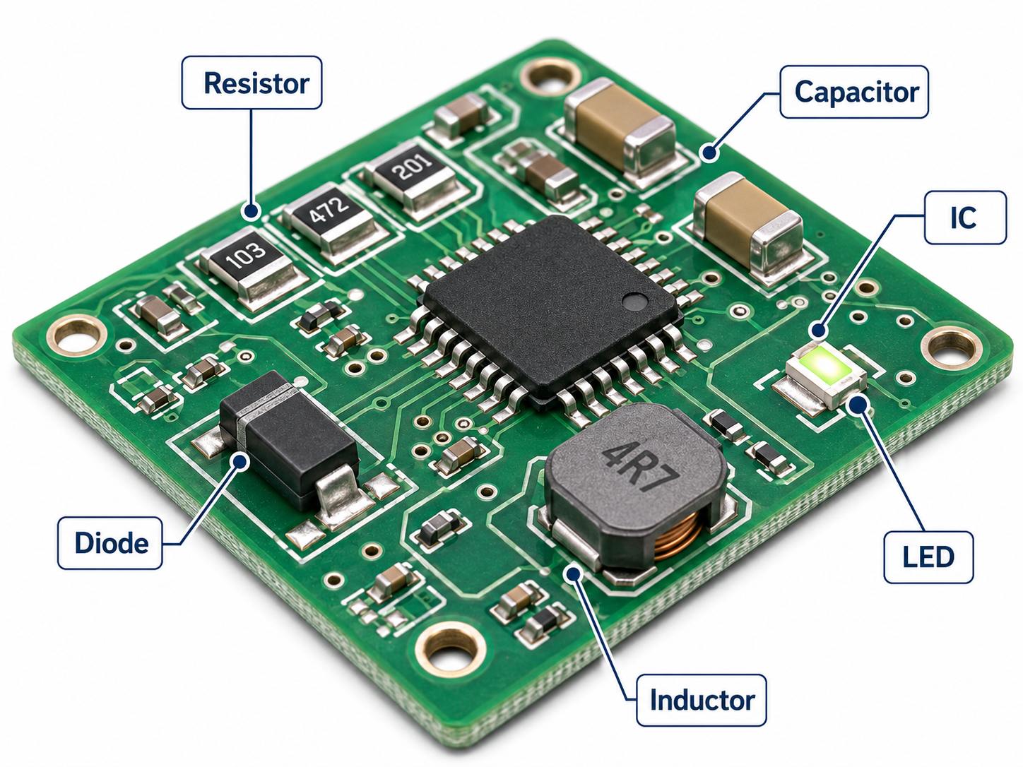
Typical SMDs include chip resistors, ceramic capacitors, inductors, diodes, transistors, integrated circuits, LEDs, sensors, connectors, and power devices. They are widely used in industrial controls, medical devices, automotive modules, communication products, and consumer electronics.
How Do Surface Mount Components Work on a PCB?
An SMD connects to the PCB through solder joints between its terminals and copper pads. Those pads connect to traces, planes, vias, and other circuit elements.
- Chip resistors and capacitors use metalized end terminals.
- SOIC and QFP packages use side leads.
- QFN and DFN packages use bottom pads.
- BGA packages use solder balls under the component.
- Power devices may include a large exposed thermal pad.
Reliable assembly depends on the PCB land pattern, solder mask clearance, stencil aperture, paste volume, placement accuracy, component orientation, and reflow profile. Layout also matters: decoupling capacitors should sit close to IC power pins, while power devices need enough copper and thermal vias to remove heat.
Main Surface Mount Types
Surface mount types are most useful when grouped by electrical function.
- Passive components: Resistors, capacitors, inductors, ferrite beads, transformers, and resistor networks.
- Discrete semiconductors: Diodes, transistors, MOSFETs, TVS devices, and regulators.
- Integrated circuits: Microcontrollers, processors, memory, amplifiers, communication ICs, and power-management devices.
- Electromechanical components: Switches, relays, connectors, microphones, and buzzers.
- Optoelectronic components: LEDs, optocouplers, photodiodes, and optical sensors.
Parts with the same external size may have very different electrical ratings. The full manufacturer part number should therefore be used for sourcing and quotation.
What Are the Most Common SMD Components and Their Functions?
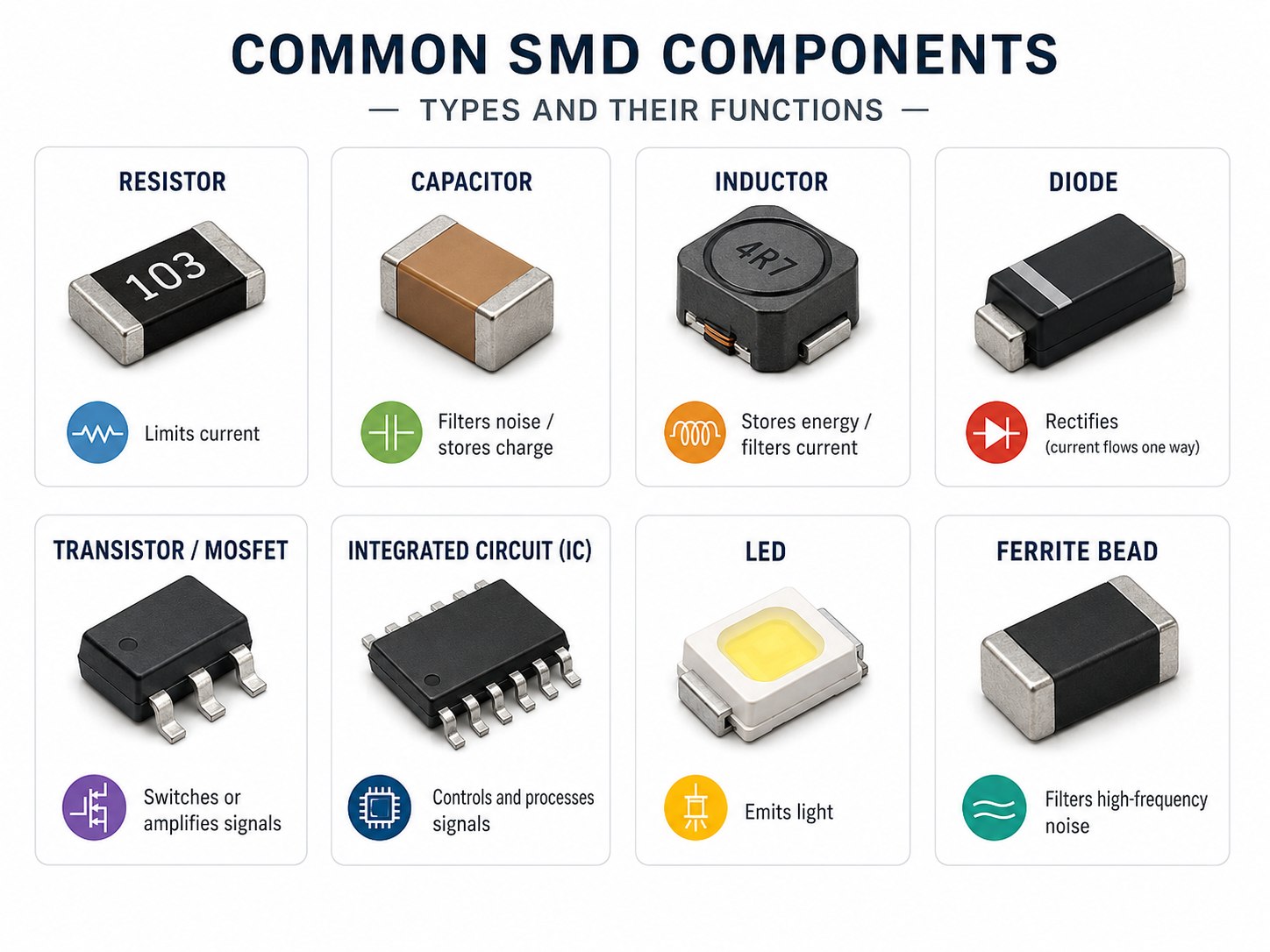
| SMD component | Main function | Key selection factors |
|---|---|---|
| Resistor | Limits current or divides voltage | Resistance, tolerance, power, temperature coefficient |
| Capacitor | Filters noise or stores charge | Capacitance, voltage, dielectric, ESR, DC bias |
| Inductor | Stores magnetic energy | Inductance, saturation current, DC resistance |
| Ferrite bead | Suppresses high-frequency noise | Impedance, current rating, resistance |
| Diode | Rectifies or protects a circuit | Forward voltage, reverse voltage, surge current |
| MOSFET | Controls power | RDS(on), gate charge, current, thermal resistance |
| Integrated circuit | Performs control or processing | Supply voltage, pin count, package, lifecycle |
| LED | Produces light | Wavelength, current, brightness, polarity |
A BOM entry such as “10 µF capacitor” is incomplete. It should also include package size, voltage rating, tolerance, dielectric type, manufacturer part number, and approved alternatives.
What Are the Standard Surface Mount Component Sizes?
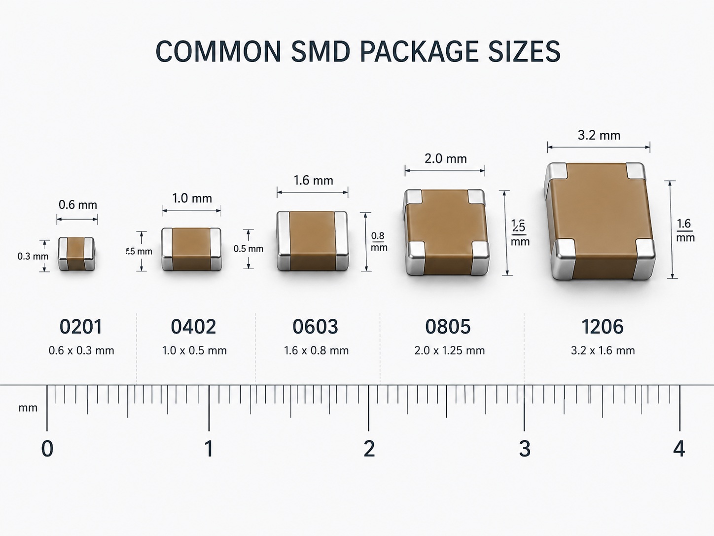
| Imperial code | Metric code | Approximate dimensions | Typical use |
|---|---|---|---|
| 01005 | 0402 | 0.4 × 0.2 mm | Wearables and ultra-compact products |
| 0201 | 0603 | 0.6 × 0.3 mm | High-density electronics |
| 0402 | 1005 | 1.0 × 0.5 mm | Compact commercial products |
| 0603 | 1608 | 1.6 × 0.8 mm | General-purpose PCB assembly |
| 0805 | 2012 | 2.0 × 1.25 mm | Prototypes and industrial boards |
| 1206 | 3216 | 3.2 × 1.6 mm | Higher power or voltage |
For many prototypes and industrial products, 0603 and 0805 packages offer a practical balance of board density, availability, assembly yield, inspection, and rework. Use 0402, 0201, or smaller parts when miniaturization or routing density provides a clear benefit.
What SMD Package Types Are Used for Semiconductors and ICs?
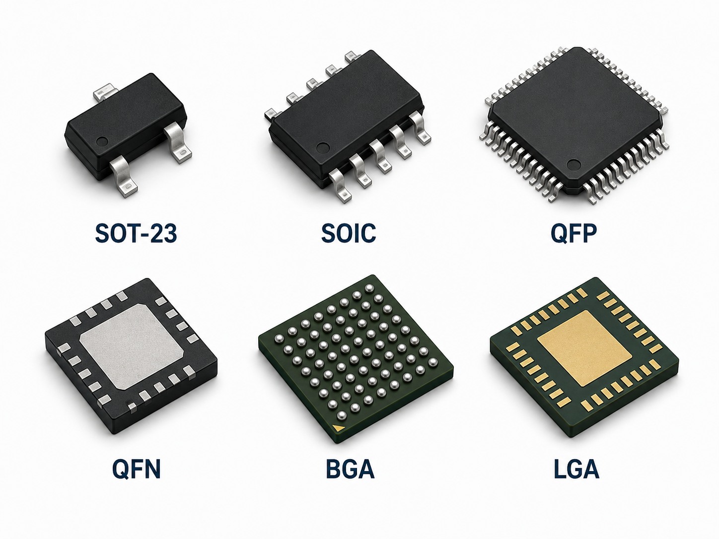
| Package family | Typical applications | Main assembly concern |
|---|---|---|
| SOT-23, SOT-89 | Transistors and regulators | Pin configuration |
| SOIC, SOP | Logic and analog ICs | Visible joints simplify AOI and rework |
| TSSOP, SSOP | Controllers and interfaces | Fine-pitch solder bridging |
| QFP, LQFP | Microcontrollers | Lead alignment and coplanarity |
| QFN, DFN | RF and compact devices | Hidden joints and exposed-pad solder volume |
| BGA | Processors, FPGAs, and memory | X-ray inspection and PCB warpage |
| LGA | Sensors and RF modules | Paste height and pad alignment |
For prototypes with frequent changes, leaded packages are easier to inspect and rework. Fine-pitch BGA, CSP, and QFN packages are justified when board space, routing density, or electrical performance requires them.
How Does Surface Mount Electronic Component Identification Work?
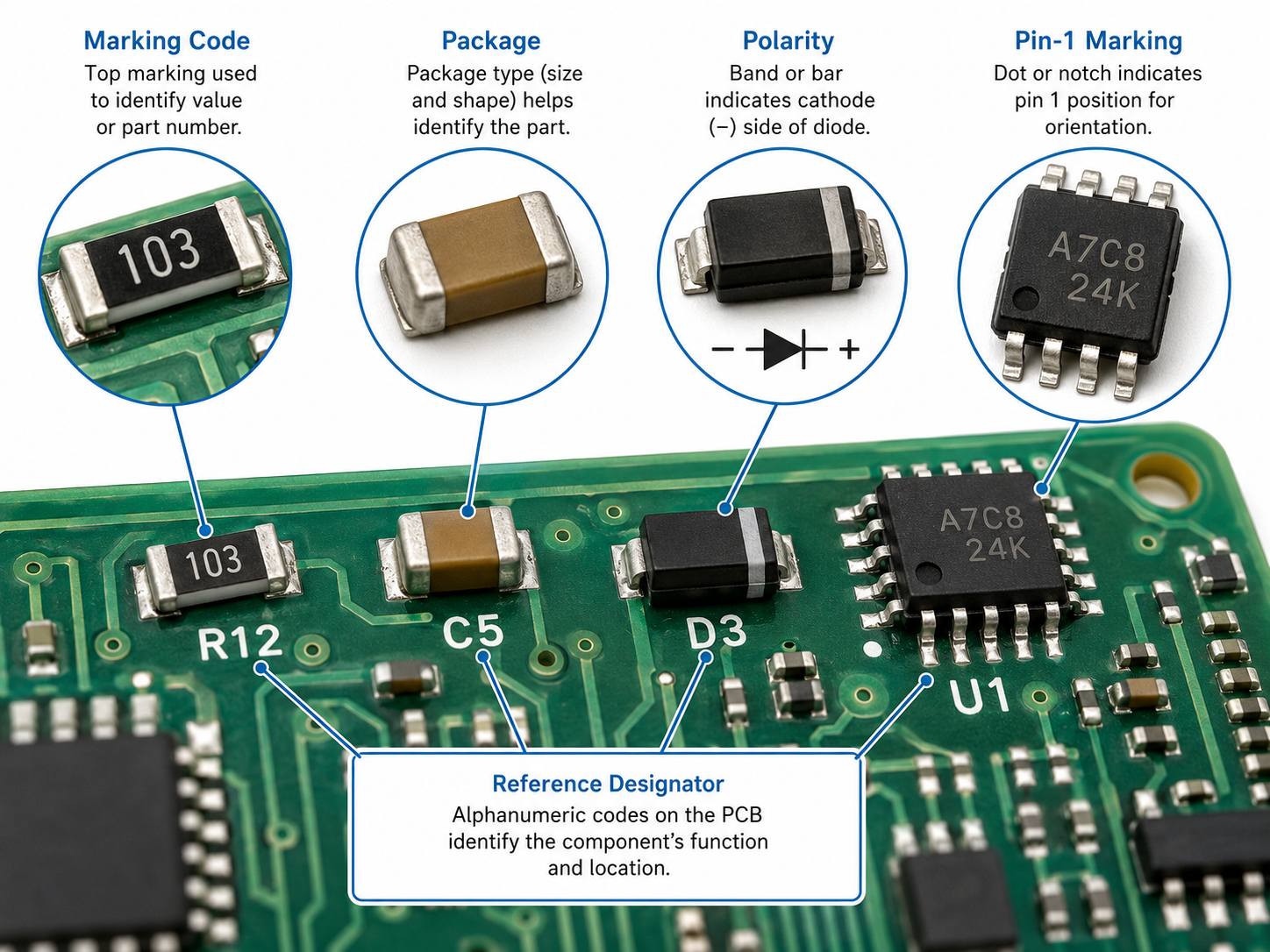
Short top codes are often reused by different manufacturers, so identification should combine several clues:
- Check the PCB reference designator.
- Record the complete top marking, including logos, dots, and separate text lines.
- Measure the package and count the terminals.
- Check polarity or pin-one indicators.
- Review the surrounding circuit.
- Compare manufacturer marking databases and datasheets.
An SMD components identification PDF can help with common resistor codes, package outlines, and symbols, but it cannot identify every device. For production, the approved BOM and manufacturer part number remain the primary references.
How Can You Read SMD Component Codes and Markings?
Resistor codes
A three-digit code uses the first two digits as the value and the third as the multiplier. For example, 472 means 4.7 kΩ, while 103 means 10 kΩ. In a four-digit code, 1001 means 1 kΩ. The letter R acts as a decimal point, so 4R7 means 4.7 Ω.
Capacitor markings
Many multilayer ceramic capacitors have no printed value. Identification normally comes from the BOM, reel label, placement records, or electrical measurement.
Diode, transistor, and IC markings
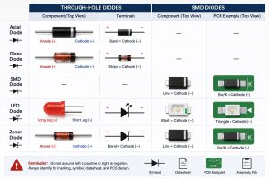
Diodes may use a band to show the cathode. Small transistors and ICs often use manufacturer-specific top codes. Always confirm the package, pinout, electrical grade, and full ordering code before sourcing a replacement.
Common SMD Component Symbols
| Reference designator | Component |
|---|---|
| R | Resistor |
| C | Capacitor |
| L | Inductor |
| FB | Ferrite bead |
| D | Diode |
| LED | Light-emitting diode |
| Q | Transistor or MOSFET |
| U or IC | Integrated circuit |
| Y or X | Crystal or resonator |
| F | Fuse |
| SW | Switch |
| J or CN | Connector |
| TP | Test point |
A schematic symbol describes electrical function, not physical size. The BOM and PCB footprint define the actual package.
What Is the Surface Mount Technology Process?
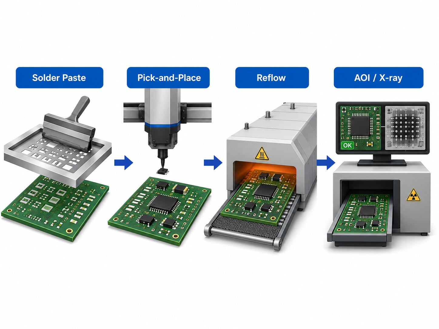
- Engineering review: Check Gerber or ODB++, BOM, centroid data, assembly drawings, polarity, firmware, and test requirements.
- PCB and component preparation: Inspect boards and control moisture-sensitive devices.
- Solder paste printing: Deposit controlled paste volumes through a stencil.
- SPI: Measure paste height, area, volume, and alignment.
- Pick-and-place: Position components using machine vision and centroid data.
- Reflow: Heat the assembly through preheat, soak, liquidus, and cooling stages.
- Inspection: Use AOI for visible joints and X-ray for BGA, QFN, LGA, and other hidden connections.
- Testing: Perform flying-probe, in-circuit, functional, programming, or customer-defined tests.
For an accurate quotation, customers should provide complete manufacturer part numbers, quantity, test requirements, approved substitutions, and delivery expectations. EBest Circuit uses this information to review component availability, package compatibility, inspection needs, and assembly risks before production.
SMD Components vs Through-Hole Components: What Is the Difference?
SMDs are preferred for compact, automated electronics. Through-hole parts remain useful where mechanical strength, high current, or easy servicing takes priority.
| Factor | SMD components | Through-hole components |
|---|---|---|
| Mounting | Soldered onto surface pads | Leads inserted through holes |
| PCB density | High | Lower |
| Assembly | Highly automated | Often needs extra soldering steps |
| High-frequency use | Better suited due to shorter paths | Longer leads add parasitic effects |
| Mechanical strength | Package-dependent | Usually stronger |
| Rework | Difficult for very small packages | Often easier |
| Typical use | ICs, passives, compact electronics | Connectors, relays, transformers |
Many boards use both methods. The practical choice should be made component by component.
What Are the Most Common SMT Component Assembly Defects?
| Defect | Common cause | Prevention |
|---|---|---|
| Tombstoning | Uneven pad heating or paste volume | Use symmetrical pads and balanced heating |
| Solder bridging | Excess paste or poor alignment | Adjust stencil apertures and placement |
| Insufficient solder | Poor paste transfer | Clean the stencil and monitor SPI |
| Open joint | Warpage, low paste, or poor wetting | Control the profile, paste, and board flatness |
| Polarity error | Incorrect rotation data | Use clear drawings and first-article checks |
| QFN voiding | Trapped flux under the thermal pad | Use segmented stencil apertures |
| Head-in-pillow | BGA warpage or oxidation | Control moisture and reflow profile |
| Cracked capacitor | PCB flex or depaneling stress | Support the board and review orientation |
When evaluating a supplier, ask how it manages first-article inspection, feeder verification, moisture-sensitive devices, reflow profiling, traceability, defect records, and functional testing.
FAQs
1. How do I identify an SMD component?
Check the reference designator, top marking, package size, pin count, and polarity marks. Then compare the information with datasheets or marking databases. Do not rely on a short top code alone.
2. What do the numbers on an SMD resistor mean?
A three-digit code uses the first two digits as the value and the third as the multiplier. For example, 472 means 4.7 kΩ. The letter R represents a decimal point.
3. What are the standard SMD component sizes?
Common passive sizes include 01005, 0201, 0402, 0603, 0805, and 1206. For general prototype and industrial work, 0603 and 0805 are often easier to assemble and rework.
4. Is 0402 smaller than 0603?
Yes. An imperial 0402 component is approximately 1.0 × 0.5 mm, while an imperial 0603 component is about 1.6 × 0.8 mm. Confirm whether the drawing uses imperial or metric codes.
5. Can SMD components be soldered by hand?
Yes. Larger packages such as 0805, 1206, SOIC, and SOT-223 can be hand-soldered. Small QFN, LGA, BGA, and 0201 packages require better process control and inspection.
6. Are SMD components better than through-hole components?
SMDs are better for compact layouts and automated production. Through-hole parts remain useful for mechanically loaded connectors, relays, transformers, and large power components.
7. Why do some SMD components have no visible markings?
Small packages may not have enough printable area. Ceramic capacitors are also commonly unmarked, so the BOM, reel label, and placement records should be used.
8. What equipment is used in the surface mount process?
A typical SMT line includes a solder paste printer, SPI, pick-and-place machines, reflow oven, AOI, X-ray equipment, rework stations, and programming or test equipment.
9. How are BGA solder joints inspected?
BGA joints are mainly inspected by X-ray because the solder balls are hidden. X-ray should be combined with electrical or functional testing.
Surface mount electronic components support compact, automated, and high-density PCB assemblies. The right package should balance electrical performance, board space, assembly capability, availability, and rework needs.
For a PCB assembly quotation, prepare the Gerber files, BOM, pick-and-place file, assembly drawing, quantity, delivery requirement, and test instructions. For prototype review, component sourcing, SMT assembly, or turnkey PCBA support, contact EBest Circuit at sales@bestpcbs.com.