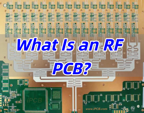
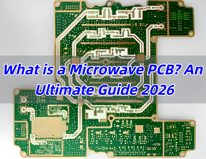
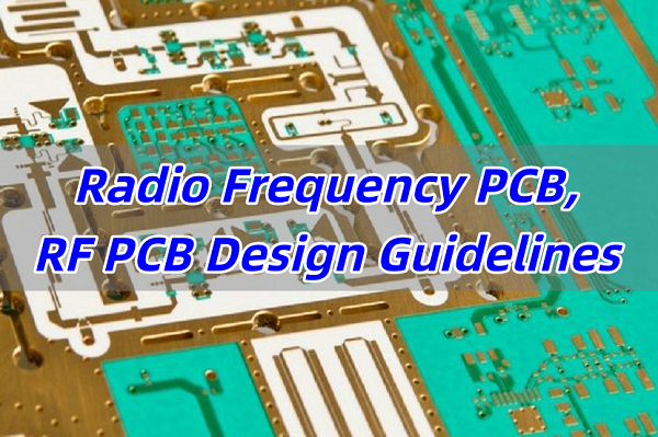
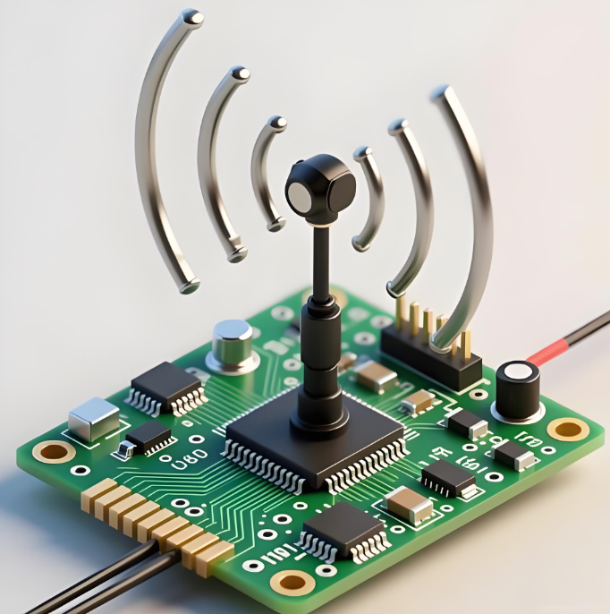
A radio frequency circuit board is a PCB designed to carry signals that are sensitive to impedance, loss, coupling, and electromagnetic behavior. In practical terms, that usually means the board layout, material choice, stackup, grounding, and connector transitions matter far more than they do on an ordinary low-speed control board.
Not every board that includes a wireless module called RF PCB. The term usually applies when the board itself must support controlled high-frequency signal behavior, such as RF transmission lines, matching networks, filters, antennas, mixers, LNAs, PAs, or microwave interconnects. Once the frequency rises, the board is no longer just a mechanical carrier. It becomes part of the circuit.
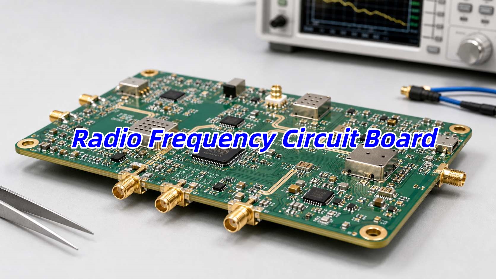
What Is a Radio Frequency Circuit Board?
A radio frequency circuit board, often called an RF PCB or high-frequency PCB, is a printed circuit board built for circuits that operate in the radio or microwave range. These boards are commonly used in wireless communication, radar, GPS, satellite systems, RF test equipment, automotive telematics, industrial sensing, medical devices, and IoT products.
The key difference from a standard FR-4 board is not just frequency. It is electrical predictability. An RF design needs controlled impedance, stable dielectric behavior, low insertion loss, good return paths, and a layout that limits radiation and coupling.
That is why the same schematic can behave very differently depending on the PCB material, copper geometry, via structure, and connector launch design.
When Is a Standard PCB Not Enough for RF Applications?
Many projects start on standard FR-4 because it is familiar and cost-effective. In some RF products, that is still the right choice. But once signal integrity, loss, or repeatability become tight, ordinary stackups may not be enough.
In general, a standard PCB becomes less suitable when the project includes:
- Controlled RF transmission lines
- High-frequency amplifiers or filters
- Antennas integrated on the board
- Low-loss signal paths over meaningful distance
- Tight phase or impedance consistency
- Microwave connectors and launch structures
- Multi-band or high-gain RF front ends
If a design only carries short RF traces between a certified module and an antenna connector, FR-4 may still be acceptable. If the board itself contains tuned RF structures, matching sections, or long controlled signal paths, material selection becomes much more critical.
Common Materials Used for RF Circuit Boards
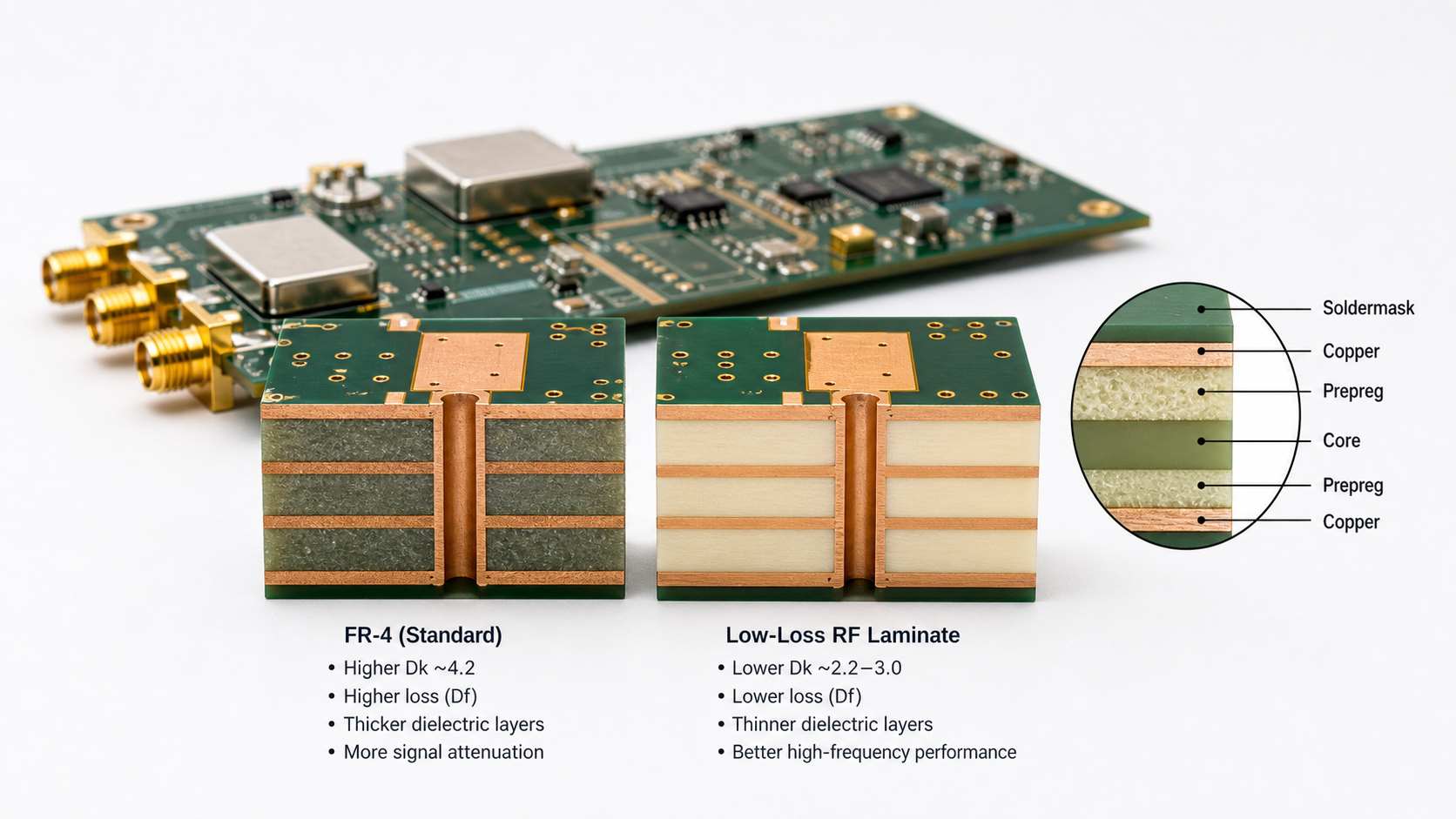
The material decision is usually driven by dielectric constant stability, dissipation factor, temperature behavior, moisture absorption, and manufacturability.
| Material Type | Typical Use | Main Advantage | Main Trade-Off |
|---|---|---|---|
| Standard FR-4 | Lower-cost RF modules, mixed digital/RF boards, short RF traces | Low cost and easy fabrication | Higher loss and less stable dielectric behavior |
| High-speed FR-4 / low-loss epoxy | Mid-range RF and mixed-signal boards | Better loss performance than standard FR-4 | Still not ideal for demanding microwave designs |
| PTFE-based laminates | Microwave, radar, satellite, low-loss RF paths | Very low loss and stable RF behavior | Higher material cost and more demanding processing |
| Hydrocarbon ceramic laminates | RF and microwave products needing a balance of cost and performance | Better dimensional and RF stability | More expensive than ordinary FR-4 |
| Hybrid stackups | Mixed RF and digital boards | Lets engineers control cost by using RF material only where needed | Lamination and DFM complexity increase |
For many buyers, the important point is this: the best RF material is not always the most expensive one. It is the one that meets loss, impedance, and stability targets without adding unnecessary fabrication difficulty.
How Material Properties Affect RF PCB Performance?
At RF frequencies, the substrate is an electrical design variable, not just a base material.
The most important properties are:
- Dielectric constant (Dk): affects trace width, signal velocity, and impedance control
- Dissipation factor (Df): affects dielectric loss and insertion loss
- Thickness tolerance: affects impedance repeatability
- Copper surface profile: affects conductor loss at higher frequencies
- Thermal stability: matters for power amplifiers and outdoor products
- Moisture absorption: matters for frequency stability and reliability in harsh environments
If the dielectric constant shifts too much across frequency or production lots, the board can move off target even when the fabrication dimensions look correct.
RF PCB Stackup and Impedance Control
A radio frequency circuit board should be designed with the stackup settled early, not after routing is nearly done.
That is because the stackup controls:
- Microstrip or stripline impedance
- Reference plane continuity
- Return current path quality
- Trace spacing and coupling
- Connector launch geometry
- Via transition behavior
Most RF boards rely on microstrip or grounded coplanar waveguide structures on outer layers, because they are easier to tune and measure. Stripline can work well too, especially where shielding and coupling control matter more than easy tuning access.
Key Layout Rules for a Radio Frequency Circuit Board
At RF, a board can fail even when the schematic is correct. Layout decisions directly affect gain, noise, return loss, spurious response, and EMC behavior.
The most important layout rules usually include:
- Keep RF traces short and direct
- Avoid unnecessary layer transitions
- Maintain continuous reference planes
- Control trace width and spacing from the beginning
- Isolate noisy digital, clock, and power-switching areas from sensitive RF paths
- Place matching components close to the device pins they tune
- Keep the ground via fence strategy consistent around critical RF regions
- Minimize stubs at connectors, pads, and test access points
For higher-frequency boards, even pad shape, solder mask opening, and connector footprint transitions can noticeably change performance.
Why Grounding Matters More in RF PCB Design?
Grounding problems are one of the most common reasons RF boards behave differently in prototype, validation, and mass production.
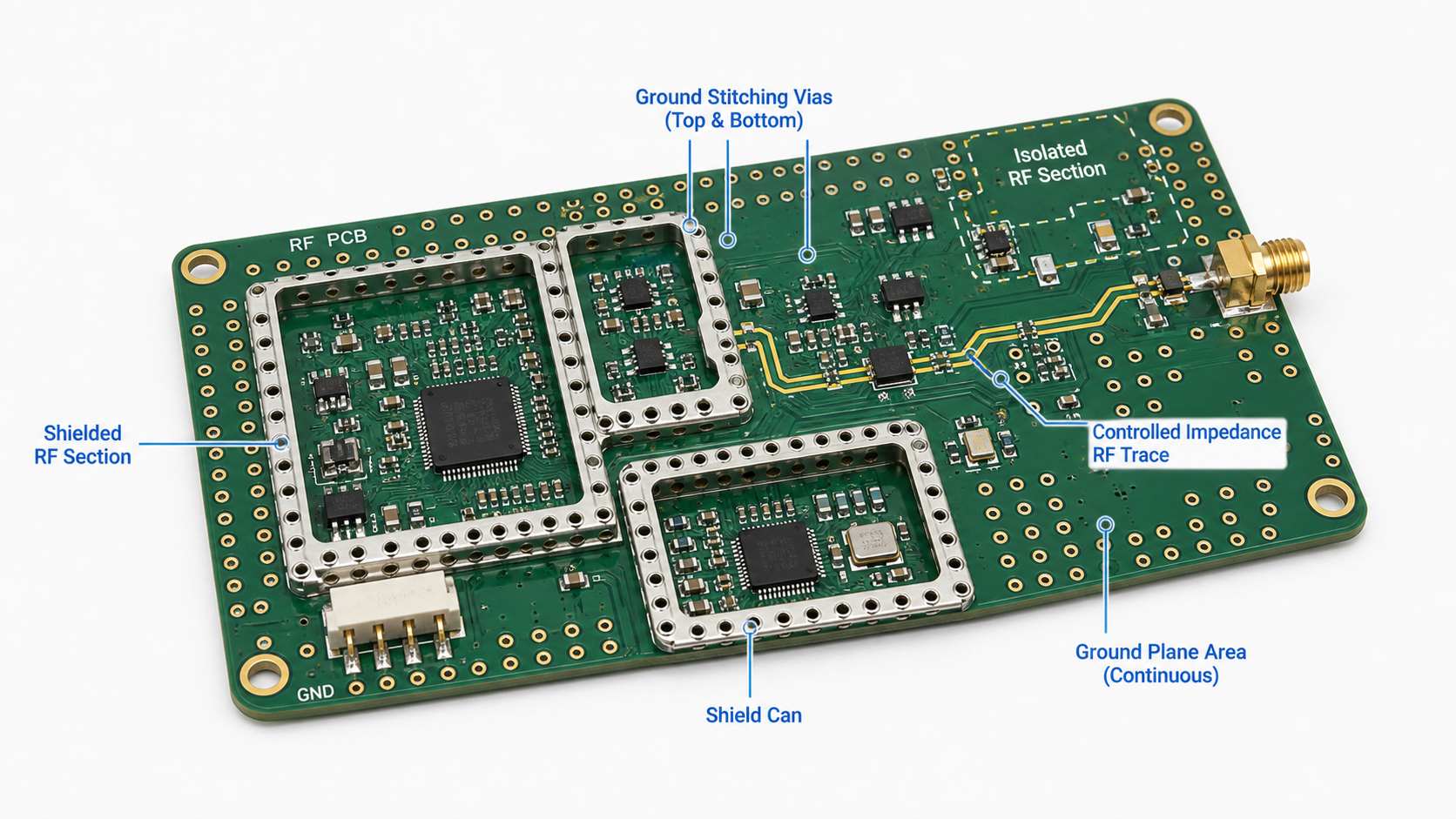
A good RF ground system is not just “more copper.” It requires a predictable return path. Gaps in reference planes, poor stitching around transmission lines, and mixed return currents from digital and RF sections can all degrade performance.
In practical RF layouts, engineers often use:
- Solid reference planes under RF traces
- Stitching vias around RF boundaries and connector launches
- Controlled grounding around antennas and shield cans
- Partitioning between RF, analog, digital, and power sections
If the grounding strategy is weak, the board may show unstable tuning, increased loss, or unexpected radiation.
Vias, Connectors, and Transitions in High-Frequency Boards
At lower frequencies, vias and connectors are mostly interconnect details. At RF, they are part of the transmission path.
The decision logic is simple: every transition adds discontinuity, so transitions should be limited and designed intentionally.
| RF Transition Element | Main Concern | Practical Design Focus |
|---|---|---|
| Signal via | Inductance and impedance discontinuity | Reduce unnecessary transitions and optimize return path vias |
| Connector launch | Reflection and mismatch | Tune pad shape, anti-pad, and ground stitch pattern |
| Test point or stub | Added discontinuity and radiation | Avoid on critical RF traces when possible |
| SMA or edge connector area | Mechanical fit and RF continuity | Keep launch geometry consistent with stackup |
| Board-to-board RF path | Coupling and loss | Short path, controlled impedance, stable connector system |
If the project includes microwave connectors, the launch region should usually be reviewed as a separate RF structure, not treated as a standard footprint.
Can FR-4 Be Used for a Radio Frequency Circuit Board?
Yes, but only within the right application boundary.
FR-4 can still be acceptable when:
- RF frequency is modest
- RF path is short
- Insertion loss is not extremely tight
- The design uses a certified RF module and the host board only carries short matched traces
- Cost sensitivity is higher than peak RF performance
FR-4 becomes less attractive when:
- Design includes long RF paths
- Can be operates at higher microwave frequencies
- phase consistency matters
- Includes integrated antennas or distributed RF structures
- Needs low loss and repeatable tuning across production lots
In other words, FR-4 is not “wrong.” It is just not universal.
Typical Applications of RF Circuit Boards
A radio frequency circuit board can appear in many industries, but the design priorities are not always the same.
Common applications include:
- Wireless communication equipment
- GPS and GNSS devices
- Wi-Fi, Bluetooth, and IoT hardware
- RF power amplifiers and front-end modules
- Radar and sensing systems
- Medical telemetry devices
- Automotive RF electronics
- Satellite and aerospace communication hardware
- RF test and measurement equipment
For example, an IoT gateway may care most about mixed-signal integration and manufacturability, while a radar board may care more about loss, phase stability, and controlled transitions.
Manufacturing Challenges of RF PCBs
RF boards are often harder to manufacture consistently than standard digital boards because electrical behavior is tied closely to fabrication details.
The most common manufacturing challenges include:
- Tighter impedance tolerance requirements
- Laminate handling differences for PTFE-based materials
- Dimensional stability during lamination
- Copper roughness effects at higher frequency
- Drill quality and registration around controlled transitions
- Hybrid stackup bonding complexity
- Solder mask influence near RF launch areas
That is why DFM review matters early. A board that works in simulation but ignores real fabrication tolerances can become expensive to debug later.
This is also where EBest Circuit (Best Technology) can be useful. For RF-related PCB or PCBA projects, the practical value is not just fabrication capacity. It is the ability to review stackup, manufacturability, material choice, and assembly fit before the project enters production.
RF PCB Assembly and Testing Considerations
RF assembly is not just ordinary SMT with different parts. Placement accuracy, connector alignment, shielding, cleaning control, and test setup can all affect final performance.
Important assembly and test concerns include:
- Connector coplanarity and solder quality
- Shield can placement and rework access
- Stability of matching network components
- Board cleanliness, especially where leakage or detuning matters
- Cable and fixture repeatability during validation
- Test method selection such as VNA measurement, insertion loss, return loss, or gain verification
For RF PCBA projects, buyers should also think ahead about whether they need bare-board delivery, assembly only, tuned prototype support, or functional RF test support.
What to Provide When Requesting a Quote for an RF Circuit Board
A useful RF quotation needs more than “board size and layer count.”
The most helpful files and notes usually include:
- Gerber or ODB++ files
- Layer stackup
- Target impedance and trace type
- Material preference or acceptable alternatives
- Operating frequency range
- Copper thickness
- Connector type and launch details
- Assembly requirement if PCBA is needed
- RF test requirement if applicable
- Prototype quantity and production forecast
If the board includes a special RF laminate, hybrid stackup, controlled launch area, or microwave connector, that should be stated clearly in the inquiry. Otherwise, the supplier may quote the board as if it were a standard PCB, which creates avoidable back-and-forth later.
How to Choose the Right RF PCB Manufacturer?
The right RF PCB supplier is not simply the one with the lowest laminate price. The better question is whether the supplier can support the actual engineering risk of the design.
A good evaluation checklist includes:
- Experience with RF and high-frequency materials
- Ability to support hybrid stackups if needed
- Impedance control capability
- Understanding of connector launch and grounding details
- Assembly support for RF components and shielding
- Test and inspection capability aligned with the product
- Willingness to review DFM issues before build
For engineers moving from prototype into production, EBest Circuit’s one-stop PCB manufacturing, component sourcing, PCBA assembly, and technical review model can reduce handoff mistakes, especially when the design mixes RF, digital control, and power sections on one board.
Conclusion
A radio frequency circuit board is not just a normal PCB running at a higher speed. It is a board whose electrical behavior depends strongly on material properties, stackup structure, grounding, trace geometry, and transitions. The right material and layout choices depend on the actual RF function, not just the frequency number alone.
If you are evaluating an RF PCB or RF PCBA project, the most practical approach is to define the frequency range, loss target, impedance structure, material options, and assembly requirements early. For RF PCB and PCBA support, contact EBest Circuit at sales@bestpcbs.com.