

Do you often encounter confusion when working with cement resistor, such as how to verify their functionality, distinguish their types, or select the right one for your project? Whether you’re troubleshooting a faulty circuit or designing a new PCB, understanding the ins and outs of cement resistors is crucial to ensuring stable performance and avoiding costly mistakes. This guide breaks down everything you need to know, from basic definitions to practical testing steps, tailored to address the common pain points you face every day.
What is a Cement Resistor?
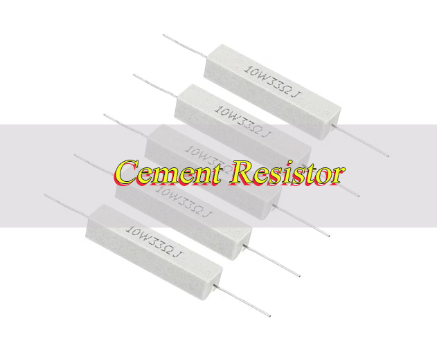
A cement resistor is a type of power resistor designed for reliable high-power operation. It is constructed by winding resistance wire, usually nickel chromium alloy around a non-alkaline ceramic core, then encapsulating the entire assembly in heat-resistant, nonflammable silicate cement for curing. This cement coating serves multiple purposes: it enhances heat dissipation, provides mechanical protection, and ensures strong insulation.
Two common variants exist: wirewound cement resistors, which use resistance wire for precise values and high power handling, and metal oxide cement resistors, which use a metal oxide film for higher resistance values and better high-frequency performance. Tinned copper leads at both ends make it easy to solder the resistor to PCBs, and its robust design ensures durability in harsh environments like high humidity or vibration.
What Are Types of Cement Resistors?
Here are types of cement resistors:
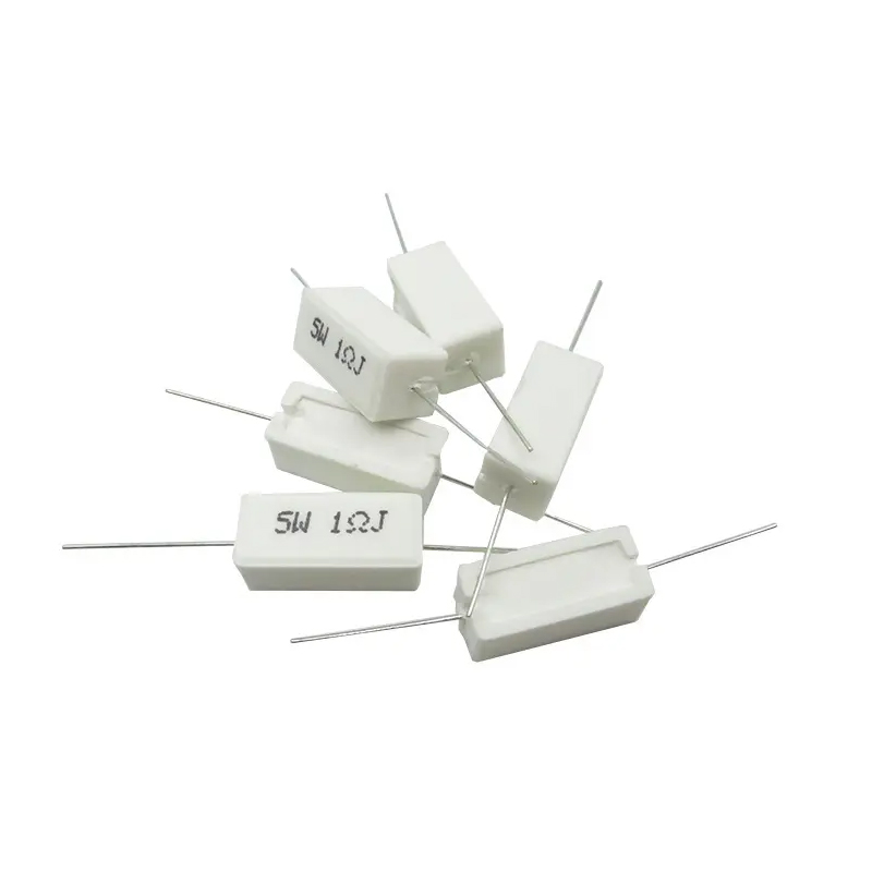
- Wirewound Cement Resistors: The most common type, made by winding nickel chromium or constantan wire around a ceramic core. They offer high power ratings (5W to 200W) and precise resistance values, with tolerances typically ranging from ±1% to ±10%. These are widely used in industrial control circuits and power supplies where stable performance under high load is required.
- Metal Oxide Cement Resistors: Constructed using metal oxide film instead of wire winding, these resistors have higher resistance values and better high-frequency performance. They are smaller in size compared to wirewound types and suitable for circuits requiring high resistance with moderate power handling (2W to 50W).
- Non-Inductive Cement Resistors: Designed with a double-wound structure that cancels out inductance, these resistors are ideal for high-frequency circuits, switch power supplies, and inverter circuits. Their inductance values are as low as 0.01μH to 1μH, preventing signal interference and ensuring circuit stability.
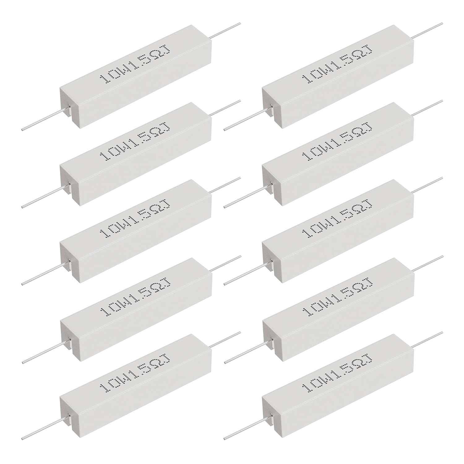
- Axial Leaded Cement Resistors: Featuring leads on both ends, these are easy to insert into PCB holes and solder, making them suitable for through-hole mounting. They come in various power ratings and are commonly used in consumer electronics and small industrial devices.
- Bolt-Mounted Cement Resistors: Equipped with bolts for secure mounting on heat sinks or metal surfaces, these are designed for high-power applications (50W and above). They efficiently dissipate heat through direct contact with cooling components, ideal for industrial machinery and power converters.
Are Cement Resistors Non Inductive?
No, not all cement resistors are non inductive. The inductance of a cement resistor depends on its construction, specifically whether it uses a standard or non-inductive winding method.
Standard wirewound cement resistors have inherent inductance due to their single-winding structure. This inductance can cause signal interference in high-frequency circuits, making them unsuitable for applications like switch power supplies or RF circuits.
Non-inductive cement resistors, however, are specially designed with a double-wound structure. Two wires are wound in opposite directions around the ceramic core, canceling out the magnetic fields each generates. This results in extremely low inductance—typically 0.01μH to 1μH, making them ideal for high-frequency applications. Always check the datasheet to confirm inductance values when selecting a cement resistor for such use cases.
How To Read And Understand Cement Resistor Codes?
Here are methods to read and understand cement resistor codes:
- Direct Marking Code: Most cement resistors have their specifications directly printed on the body, including resistance value, power rating, and tolerance. For example, “100Ω 10W ±5%” means the resistor has a resistance of 100 ohms, a power rating of 10 watts, and a tolerance of ±5%. This is the simplest and most common coding method, easy to read at a glance.
- Color Band Code: Some smaller cement resistors use color bands to indicate resistance and tolerance, following the EIA standard. The first two bands represent the significant digits, the third band is the multiplier, and the fourth band (if present) is the tolerance. For example, brown, black, red, gold translates to 10 x 10² = 1000Ω (1kΩ) with ±5% tolerance.
- Letter and Number Code: This code uses a combination of letters and numbers to represent resistance. The letters “K” (kiloohm) and “M” (megaohm) indicate the multiplier, while the numbers represent the significant digits. For example, “2K2J” means 2.2kΩ with ±5% tolerance (J = ±5%), and “1M5F” means 1.5MΩ with ±1% tolerance (F = ±1%).
- Power Rating Code: Some manufacturers use letters to denote power ratings, such as “A” for 1W, “B” for 2W, “C” for 3W, up to “Z” for 25W. Double letters like “AA” indicate 50W, “BB” for 100W. Always cross-verify with the datasheet to confirm the power rating, as different manufacturers may have slight variations.
- Temperature Coefficient Code: The temperature coefficient (TCR) is sometimes marked with letters, such as “H” for ±100ppm/°C, “K” for ±200ppm/°C. This indicates how much the resistance changes with temperature, critical for precision circuits.
What Details Does A Cement Resistor Datasheet Include?
| Datasheet Detail | Description |
|---|---|
| Part Number | Unique identifier for the cement resistor, used for ordering and inventory management. It often includes information about power rating, resistance, and package type. |
| Nominal Resistance | The specified resistance value at 25°C, measured in ohms (Ω), kiloohms (kΩ), or megaohms (MΩ). It is the core parameter for circuit design. |
| Tolerance | The allowable deviation from the nominal resistance, typically ±1%, ±5%, or ±10%. Precision circuits require lower tolerance (±1% or ±2%). |
| Rated Power | The maximum power the cement resistor can dissipate continuously at 25°C without damage. Power ratings range from 2W to 200W, with derating required at higher ambient temperatures. |
| Operating Temperature Range | The minimum and maximum temperatures the resistor can operate in, typically -55°C to +155°C for industrial-grade cement resistors. Exceeding this range reduces lifespan. |
| Temperature Coefficient (TCR) | Expressed in ppm/°C, it measures how resistance changes with temperature. Typical values for cement resistors are ±100ppm/°C to ±500ppm/°C. |
| Inductance | Critical for high-frequency applications. Non-inductive cement resistors have inductance values ≤1μH, while standard wirewound types may have 0.1μH to 10μH. |
| Maximum Working Voltage | The highest voltage the resistor can withstand continuously without insulation breakdown. Typical values range from 250V to 1000V, with high-voltage variants up to 2000V. |
| Package Dimensions | Physical size of the resistor, including length, width, height, and lead diameter/span. Important for PCB layout and mounting space. |
| Certifications | Compliance with industry standards such as RoHS, UL, and CE, ensuring the resistor meets safety and environmental requirements for global markets. |
What is a Cement Resistor Used for?
Here are applications of cement resistors:
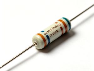
- Power Supply Circuits: Used as load resistors, current-limiting resistors, and discharge resistors in AC/DC power supplies. They dissipate excess power and stabilize output voltage, ensuring the power supply operates within safe limits.
- Industrial Machinery: Employed in motor control circuits, such as brake resistors for servo motors and current-limiting resistors for motor starters. Their high power handling and durability make them suitable for harsh industrial environments.
- Consumer Electronics: Found in televisions, air conditioners, and audio amplifiers. They act as power resistors in the power supply section, handling high currents and dissipating heat efficiently.
- Switch Power Supplies and Inverters: Non-inductive cement resistors are used in buffer circuits and snubber circuits to suppress voltage spikes and reduce interference, ensuring stable operation of high-frequency circuits.
- Test Equipment: Used as dummy load resistors in test benches to simulate circuit loads, allowing engineers to test the performance of power supplies and other electronic devices.
- Automotive Electronics: Installed in automotive power systems, such as battery charging circuits and motor control units. They withstand high temperatures and vibrations, meeting automotive-grade reliability standards.
Are Cement Resistors Good For Electronic Projects?
Yes, cement resistors are excellent for many electronic projects, particularly those that prioritize power handling, heat dissipation, and durability. Their key advantages make them a reliable choice for a wide range of applications.
Their cement encapsulation and ceramic core enable superior heat dissipation compared to carbon or metal film resistors, preventing overheating even under continuous high-load conditions. They are also resistant to moisture, vibration, and mechanical damage, making them suitable for both indoor and outdoor projects, as well as industrial prototypes and mass-produced devices.
Cement resistors are also cost-effective, especially for high-power applications. However, they are larger than standard resistors, so they are not ideal for compact projects with limited space. For low-power, small-scale projects, smaller alternatives like carbon film or SMD resistors are more appropriate.
What are Differences between Cement Resistor vs Ceramic Resistor?
| Parameter | Cement Resistor | Ceramic Resistor |
| Construction | Wirewound or metal oxide film on ceramic core, encapsulated in silicate cement with tinned copper leads. | Alumina ceramic tube with spiral-wound alloy wire, coated in high-temperature epoxy or silicone rubber insulation. |
| Rated Power | 5W to 200W, single units capable of high power handling without parallel connection. | 1W to 500W, often requiring multiple units in parallel for very high power needs. |
| Inductance | Standard types: 0.1μH to 10μH; non-inductive types: 0.01μH to 1μH. | 0.1μH to 10μH, high-frequency variants can be non-inductive (≤1μH). |
| Temperature Coefficient (TCR) | ±100ppm/°C to ±500ppm/°C, affected by cement expansion. | ±50ppm/°C to ±200ppm/°C, more stable due to ceramic core material. |
| Maximum Working Voltage | 250V to 1000V, cement encapsulation limits high-voltage performance. | 500V to 5kV, better insulation for high-voltage applications. |
| Cost | 0.1 to 0.5 USD per watt, cost-effective for mass production. | 0.5 to 10 USD per watt, more expensive, especially for high-power models. |
| Mechanical Strength | Lower impact resistance (<50g), cement can crack if shocked or dropped. | Higher impact resistance (>100g), ceramic core is more durable. |
| Typical Applications | Power supplies, motor control, consumer electronics, test loads. | High-voltage circuits, RF power supplies, aerospace, marine equipment. |
How to Test Cement Resistor?
Here is a detailed steps to how to test cement resistor:
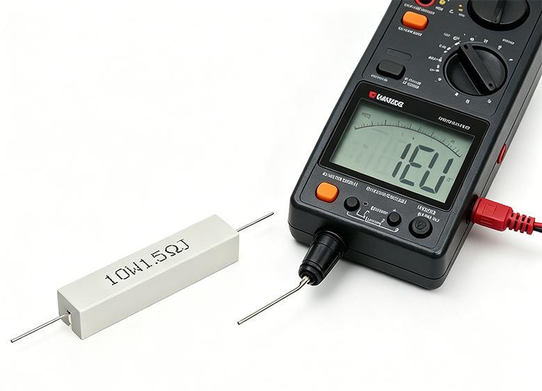
1. Prepare Test Tools: Gather a digital multimeter (DMM), a power supply (optional for load testing), and a heat sink (for high-power testing). Ensure the multimeter is calibrated to measure resistance accurately, and set it to the appropriate resistance range (ohms). Clean the cement resistor’s leads with a small brush to remove dirt or oxidation, which can affect test results.
2. Visual Inspection: Before testing, check the cement resistor for physical damage. Look for cracks in the cement encapsulation, broken or bent leads, or signs of overheating (discoloration or burn marks). If any damage is found, the resistor is likely faulty and should be replaced immediately.
3. Disconnect Power: If the cement resistor is installed in a circuit, turn off the power supply and disconnect the resistor from the circuit. This prevents voltage from interfering with the test and ensures safety. Never test a resistor while it is still connected to a live circuit.
4. Measure Resistance: Connect the multimeter’s test probes to the two leads of the cement resistor. Ensure the probes make firm contact with the leads (avoid touching the cement body, as this can affect readings). Record the measured resistance value and compare it to the nominal resistance marked on the resistor or in the datasheet. A valid resistor should have a measured value within the specified tolerance (e.g., ±5% for a 100Ω resistor means 95Ω to 105Ω is acceptable).
5. Test for Open Circuit: If the multimeter shows “OL” (overload) or a very high resistance (far above the nominal value), the cement resistor is open-circuited and faulty. This usually occurs due to broken resistance wire inside the encapsulation, often caused by overheating or mechanical damage.
6. Test for Short Circuit: If the measured resistance is near 0Ω (significantly lower than the nominal value), the resistor is short-circuited. This is typically caused by cement carbonization or internal wire damage, and the resistor must be replaced.
7. Load Test (Optional): For high-power cement resistors, perform a load test to verify power handling. Connect the resistor to a power supply set to the appropriate voltage (calculated using P = V²/R, where P is the rated power and R is the nominal resistance). Monitor the resistor’s temperature and the multimeter’s current reading for 5 to 10 minutes. A healthy resistor will maintain stable temperature and current without overheating or damage.
8. Record and Compare Results: Document all test readings, including resistance, current, and temperature. Compare the results to the datasheet specifications to confirm the cement resistor is functioning correctly. If any readings are outside the acceptable range, replace the resistor and retest to ensure circuit stability.
How To Choose Suitable Cement Resistor For Your Project?
Here is a selection guide to cement resistor for your project:
- Determine Power Requirement: Calculate the maximum power the resistor will dissipate using the formula P = I²R or P = V²/R, where I is the current and V is the voltage across the resistor. Select a cement resistor with a rated power 1.5 to 2 times the calculated power to provide a safety margin and prevent overheating.
- Select Resistance Value and Tolerance: Choose the nominal resistance value based on your circuit design. For precision circuits (e.g., measurement equipment), select a tolerance of ±1% or ±2%. For general applications, ±5% or ±10% is sufficient and more cost-effective.
- Check Inductance Requirements: If your project involves high-frequency circuits (above 100kHz), select a non-inductive cement resistor with inductance ≤1μH to avoid signal interference. For low-frequency circuits, standard wirewound cement resistors are acceptable.
- Consider Operating Temperature: Ensure the cement resistor’s operating temperature range matches your project’s environment. For high-temperature applications (above 100°C), select a resistor with a wide temperature range (-55°C to +155°C) and consider adding a heat sink.
- Choose Package Type: Select an axial leaded cement resistor for through-hole PCB mounting, or a bolt-mounted type for high-power applications requiring direct heat dissipation. Ensure the package dimensions fit your PCB layout or mounting space.
- Verify Certifications: If your project is for global markets, select a cement resistor compliant with RoHS, UL, and CE certifications to meet safety and environmental standards. This is crucial for consumer electronics and industrial products.
- Balance Cost and Performance: For mass-produced projects, prioritize cost-effective standard cement resistors. For high-reliability applications (e.g., medical equipment, automotive electronics), invest in high-quality resistors with tighter tolerances and better temperature stability.
Where To Find Reliable Cement Resistors Suppliers For Wholesale?
Here are methods about find reliable cement resistors suppliers for wholesale:
- Global Electronic Component Distributors: Established distributors like Mouser Electronics, Digi-Key, and Arrow Electronics offer a wide range of cement resistors from reputable manufacturers. They provide wholesale pricing, bulk ordering options, and reliable shipping, making them ideal for large-scale projects.
- Manufacturer Direct Sales: Contact cement resistor manufacturers directly, such as Ohmite, Vishay, and Taitron Components. Many manufacturers offer wholesale discounts for bulk orders and can provide custom solutions (e.g., non-inductive, high-voltage) tailored to your project needs.
- Online B2B Platforms: Platforms like Alibaba, Global Sources, and Made-in-China connect you with verified wholesale suppliers. Look for suppliers with high ratings, positive customer reviews, and ISO certifications to ensure product quality. Always request sample testing before placing large orders.
- Local Electronic Component Wholesalers: For urgent orders or small bulk quantities, local wholesalers can provide quick delivery and personalized support. They often stock common cement resistor types and can source hard-to-find variants on request.
- Industry Trade Shows: Attend electronic component trade shows (e.g., Electronica, CES) to connect with suppliers in person. This allows you to inspect product samples, negotiate pricing, and build long-term relationships with reliable manufacturers and distributors.
- Professional Networks: Join electronic engineering forums and communities (e.g., Reddit’s r/ElectricalEngineering, EEWeb) to get recommendations from peers. Other professionals can share their experiences with reliable suppliers and help you avoid low-quality products.
FAQs About Cement Resistors
Q1: Are cement resistors good?
A1: Yes, cement resistors are good for many applications, especially those requiring high power handling, heat dissipation, and durability. They are cost-effective, resistant to moisture and vibration, and available in various types to suit different circuit needs. They are ideal for power supplies, motor control, and industrial equipment, though they are larger than standard resistors and may not be suitable for compact projects.
Q2: Where to buy ceramic cement power resistors?
A2: Ceramic cement power resistors can be bought from global distributors like Mouser, Digi-Key, and Arrow Electronics, which offer wholesale and retail options. You can also purchase them directly from manufacturers like Ohmite and Vishay, or through B2B platforms like Alibaba and Global Sources. Local electronic wholesalers may also stock them for quick delivery.
Q3: What is a 3wk 2-0.22ohm non inductive cement resistor used for?
A3: A 3W 0.22ohm non inductive cement resistor is commonly used in high-current, high-frequency circuits. It is ideal for current sensing, snubber circuits, and discharge circuits in switch power supplies and inverters. Its low inductance (≤1μH) prevents signal interference, while its 3W power rating allows it to handle moderate power dissipation. It is often used in automotive electronics and industrial control systems.
Q4: Can cement resistors be used in high-temperature environments?
A4: Yes, most cement resistors are designed to operate in high-temperature environments, with typical operating temperature ranges of -55°C to +155°C. Their cement encapsulation and ceramic core provide excellent heat dissipation, allowing them to withstand continuous high temperatures without damage. For extremely high-temperature applications, select a resistor with a wider temperature range and consider adding a heat sink.
Q5: Do cement resistors need a heat sink?
A5: Cement resistors do not always need a heat sink, but it is recommended for high-power applications (20W and above) or when operating in high-ambient temperatures. A heat sink helps dissipate excess heat, preventing the resistor from overheating and extending its lifespan. Bolt-mounted cement resistors are designed to be attached to heat sinks for efficient heat transfer.
Q6: Can cement resistors be used in AC and DC circuits?
A6: Yes, cement resistors can be used in both AC and DC circuits. They are not polarity-sensitive, so they can be connected in any direction. Their power handling and heat dissipation capabilities make them suitable for both AC power supplies and DC circuits, such as battery charging systems and motor control circuits.
Q7: How long do cement resistors last?
A7: The lifespan of a cement resistor depends on its operating conditions, but typically ranges from 20,000 to 50,000 hours when operated within its rated power and temperature range. Factors like overloading, high ambient temperature, and mechanical damage can reduce lifespan. Using the resistor within its specifications and adding a heat sink when needed will maximize its longevity.
You may also like


Tags: Cement Resistor, cement resistor codes, Cement Resistor Datasheet, Cement Resistors Suppliers