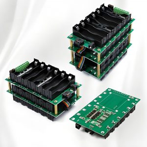
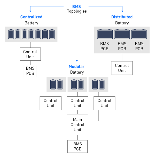
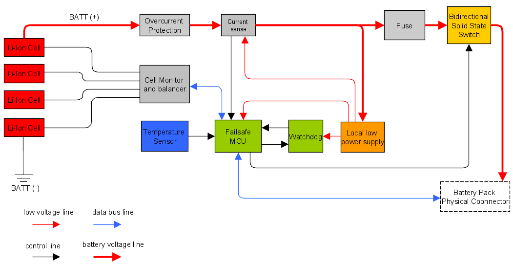
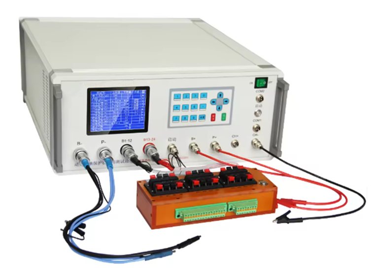
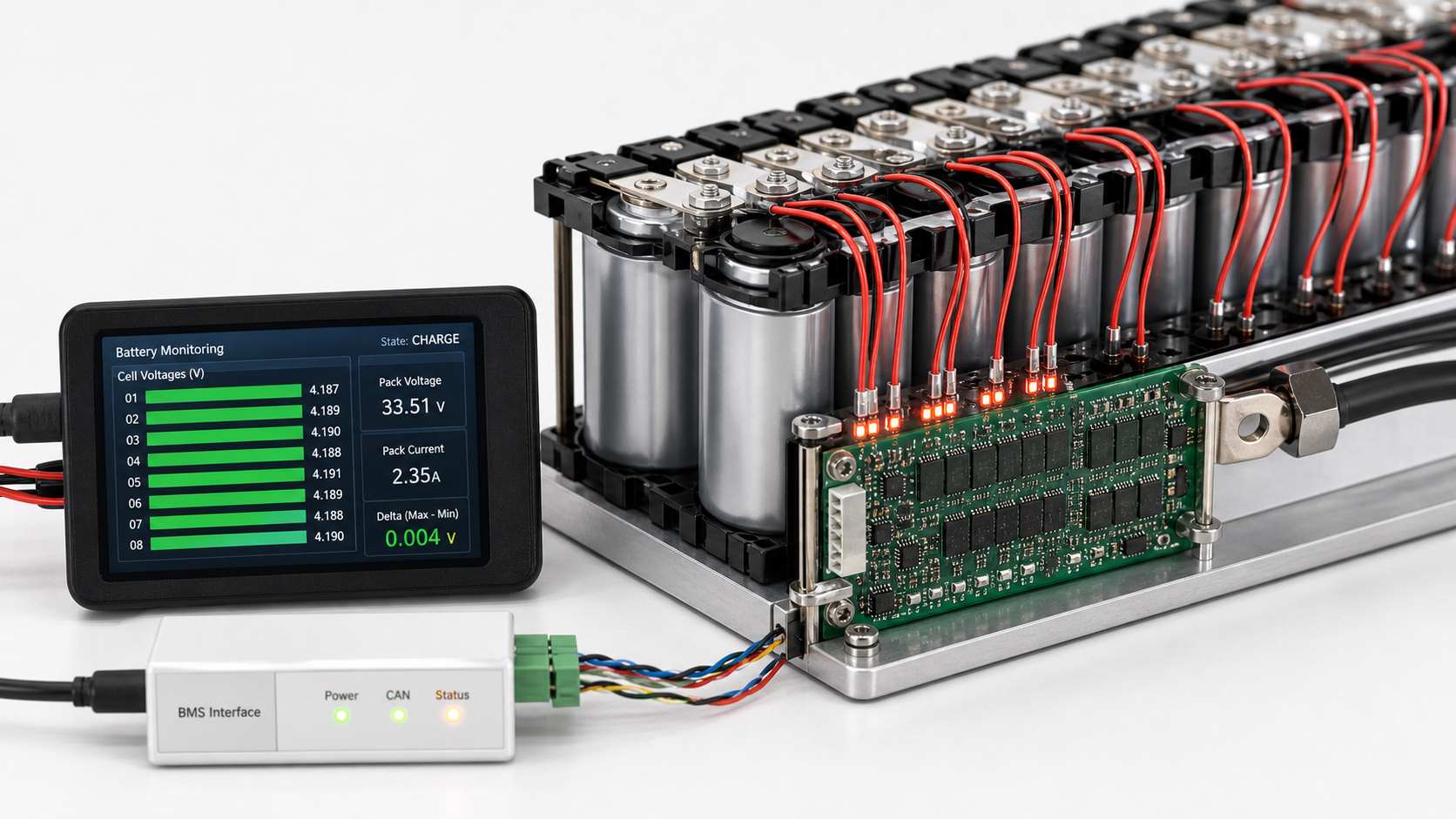
In a BMS, small voltage variation between battery cells is normal. A well-balanced lithium battery pack may show only a few millivolts to around 30mV difference between cells at rest. A difference of 30–50mV may be enough to trigger balancing in some BMS designs, while 100mV or more should be checked carefully, especially near full charge or full discharge.
However, there is no single “safe voltage variation” number for every battery pack. The acceptable range depends on battery chemistry, cell count, state of charge, load current, temperature, cell aging, BMS measurement accuracy, and the protection settings used in the design. For example, common Li-ion cells often charge to about 4.20V per cell with a tolerance of around ±50mV, while LiFePO4 cells use a lower full-charge voltage.
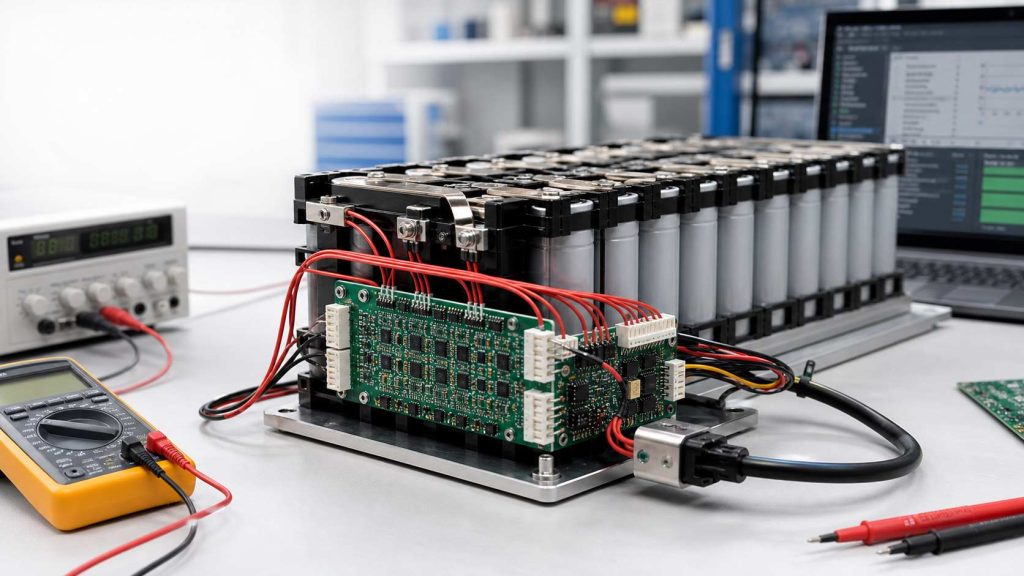
How Much Can Voltage Vary in a BMS?
What Does Voltage Variation Mean in a BMS?
Voltage variation in a BMS can mean several different things. This is why many battery problems are misunderstood at the beginning.
First, it can refer to pack voltage variation. This means the total voltage of the battery pack changes during charging, discharging, resting, or under load. A 10S lithium-ion pack, for example, may move from around 42.0V when fully charged to a much lower voltage during discharge.
Second, it can refer to cell-to-cell voltage difference. This is usually the most important value inside a BMS. In a series-connected battery pack, the BMS monitors each cell group. If one cell group is higher or lower than the others, the pack may become unbalanced.
Third, voltage variation can mean voltage sag under load. When the battery provides current to a motor, inverter, heater, pump, or power module, the voltage may drop. This drop can come from cell internal resistance, busbars, connectors, MOSFETs, PCB copper resistance, and wiring.
Fourth, voltage variation can also come from measurement deviation. A BMS reading may not exactly match a multimeter reading if the two measurements are taken at different points, at different times, or under different current conditions.
So before judging whether voltage variation is safe, it is important to identify which voltage is being discussed: pack voltage, cell voltage, loaded voltage, resting voltage, or measured voltage.
How Much Can Cell Voltage Vary in a BMS?
For many lithium battery packs, a small cell voltage difference is normal. A new, well-matched pack may stay within a few millivolts when fully rested. In real use, a difference of 10–30mV is often considered normal for many packs. A difference of 30–50mV may need balancing, depending on the BMS design. A difference above 100mV is usually worth checking, especially if it appears near the top or bottom of the charge range.
A useful practical reference is shown below:
| Cell Voltage Difference | Practical Meaning |
|---|---|
| 0–10mV | Very well balanced pack |
| 10–30mV | Usually acceptable in many lithium packs |
| 30–50mV | May trigger balancing in some BMS designs |
| 50–100mV | Needs attention, especially near full charge or low charge |
| Over 100mV | Possible imbalance, weak cell, aging, or connection issue |
Warm Notice:
This table should be treated as an engineering reference, not a universal standard. Some battery packs work with tighter limits, especially in electric vehicles, medical devices, robotics, and energy storage systems. Other lower-cost applications may allow wider differences, but they still need safe overvoltage and undervoltage protection.
What Is a Normal Voltage Difference Between Battery Cells?
A normal voltage difference depends strongly on when the measurement is taken. A cell difference measured during high-current discharge does not have the same meaning as a cell difference measured after the battery has rested for one hour.
For a healthy lithium battery pack at rest, a small difference is expected. If all cells are similar in capacity, internal resistance, temperature, and aging condition, the cell voltages should stay close. But when the pack is charging or discharging, the difference may become larger for a short time.
The most useful time to judge cell balance is usually:
- after the pack has rested
- near the upper charge region
- near the lower discharge region
- and after several normal charge-discharge cycles
Cell imbalance becomes more serious when the same cell is always higher during charging or always lower during discharging. A weak cell often fills faster and empties faster than the others.
How Much Can Pack Voltage Vary During Charge and Discharge?
Pack voltage varies much more than cell-to-cell voltage difference. This is normal because total pack voltage follows the state of charge.
The basic formula is simple:
Pack voltage = cell voltage × number of cells in series
For a common Li-ion pack, each cell may charge to around 4.20V. Therefore, pack voltage rises as the number of series cells increases.
| Battery Pack | Series Cells | Approx. Full Voltage for Li-ion | Approx. Lower Discharge Reference |
|---|---|---|---|
| 3S Li-ion | 3 cells | 12.6V | around 9.0V |
| 4S Li-ion | 4 cells | 16.8V | around 12.0V |
| 10S Li-ion | 10 cells | 42.0V | around 30.0V |
| 13S Li-ion | 13 cells | 54.6V | around 39.0V |
| 16S Li-ion | 16 cells | 67.2V | around 48.0V |
These numbers are only general references. Actual protection limits should always follow the cell datasheet, battery chemistry, charger design, product safety requirements, and BMS settings.
This is why BMS design must monitor individual cells, not only total pack voltage. A 10S pack may show a normal total voltage while one cell group is already too high or too low.
How Does Battery Chemistry Affect BMS Voltage Variation?
Battery chemistry has a direct influence on voltage limits. A voltage that is normal for one chemistry may be unsafe or incorrect for another.
| Battery Chemistry | Nominal Cell Voltage | Common Full Charge Voltage | Common Discharge Cutoff Reference |
|---|---|---|---|
| Li-ion / NMC / LCO | 3.6V or 3.7V | around 4.20V | around 3.0V |
| LiFePO4 | 3.2V | around 3.65V | around 2.5V |
| LTO | around 2.3V | often around 2.7–2.8V | often around 1.5–1.8V |
LiFePO4 is a good example. It has a flatter voltage curve than many Li-ion chemistries. This makes voltage-based state-of-charge estimation more difficult in the middle of the discharge range. A small voltage change may represent a large capacity change, depending on where the cell is on the curve.
For EVE LiFePO4 cells, one product specification lists standard charging to 3.65V and standard discharge cutoff at 2.5V under defined test conditions. This is different from common 4.20V Li-ion cells, so the BMS thresholds must be chemistry-specific.
Why Does Voltage Drop Under Load in a BMS?
Voltage drop under load is also called voltage sag. It happens when the battery delivers current and the internal resistance of the electrical path causes a voltage loss.
Voltage sag can come from several areas:
- Cell internal resistance
- Busbar resistance
- Nickel strip resistance
- Connector resistance
- Cable resistance
- MOSFET on-resistance
- Fuse resistance
- PCB copper resistance
- Solder joint quality
- Temperature
At low current, the voltage drop may be small. At high current, it can become much larger. This is why electric bikes, power tools, drones, AGVs, solar energy storage systems, and industrial battery packs need careful current-path design.
Why Do Cell Voltages Become Unbalanced?
Cell voltage imbalance usually develops from small differences between cells. Even cells from the same batch are not perfectly identical. Over time, these differences can grow.
Common causes include:
- different cell capacities,
- different internal resistance values,
- cell aging,
- temperature gradient inside the pack,
- uneven self-discharge,
- inconsistent welding quality,
- poor busbar contact,
- loose sense wires,
- inaccurate BMS voltage sensing,
- and different current sharing in parallel groups.
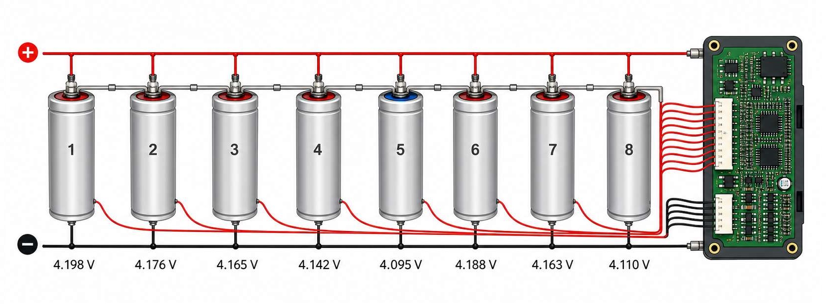
In a series battery pack, the weakest cell group controls the usable capacity of the whole pack. If one cell group reaches the upper voltage limit first, the BMS may stop charging even though other cells are not fully charged. If one cell group reaches the lower voltage limit first, the BMS may stop discharging even though other cells still have energy.
How Does a BMS Balance Cell Voltage?
A BMS balances cell voltage to keep series-connected cells closer in state of charge. The two main balancing methods are passive balancing and active balancing.
| Balancing Type | How It Works | Main Advantage | Common Limitation |
|---|---|---|---|
| Passive balancing | Bleeds extra energy from higher-voltage cells through resistors | Simple and cost-effective | Energy is dissipated as heat |
| Active balancing | Transfers energy from higher cells to lower cells or to the pack | Higher efficiency | More complex and costly |
The right choice depends on pack size, current level, cost target, energy efficiency, heat control, and application requirements. For large energy storage systems and EV battery packs, active balancing may offer strong benefits. For many consumer, industrial, and backup-power products, passive balancing remains widely used.
When Is BMS Voltage Variation Dangerous?
Voltage variation becomes dangerous when one or more cells move outside the safe operating area. The most serious conditions are overvoltage, undervoltage, excessive voltage difference, rapid voltage drift, and abnormal temperature rise.
You should pay attention when:
- one cell reaches overvoltage before the others,
- one cell drops to undervoltage much earlier than the others,
- cell voltage difference keeps increasing after every cycle,
- the BMS cuts off charging too early,
- the BMS cuts off discharge too early,
- the pack becomes hot during charge or discharge,
- one cell voltage changes faster than the others,
- the BMS reading differs greatly from a calibrated meter,
- or the pack loses capacity quickly.
Why Is the BMS Voltage Reading Different From a Multimeter?
A BMS voltage reading may not match a multimeter reading exactly. This does not always mean the BMS is faulty.
Common reasons include:
- the BMS and multimeter measure at different points,
- current is flowing during measurement,
- voltage drops across cables or connectors,
- the BMS has ADC tolerance,
- the multimeter has its own accuracy tolerance,
- the BMS sampling rate creates a time delay,
- balancing is active during measurement,
- the sense wire is loose,
- electrical noise affects the analog front end,
- or the PCB layout introduces measurement error.
For example, measuring pack voltage at the output connector may give a different value from measuring directly at the cell terminals. If current is flowing, cable and MOSFET voltage drop can create a visible difference.
How Should BMS Voltage Limits Be Set?
BMS voltage limits should always be based on the battery cell datasheet and the product’s safety requirements. Guessing these values can reduce pack life or create safety risks.
Important voltage parameters include:
| BMS Parameter | What It Controls |
|---|---|
| Cell overvoltage protection | Stops charging when one cell is too high |
| Cell undervoltage protection | Stops discharge when one cell is too low |
| Pack overvoltage protection | Protects the whole pack during charging |
| Pack undervoltage protection | Protects the whole pack during discharge |
| Recovery voltage | Defines when the BMS can return to normal operation |
| Balancing start voltage | Defines when balancing is allowed to begin |
| Balancing delta voltage | Defines how much cell difference triggers balancing |
| Protection delay time | Prevents false triggering from short transients |
For products such as e-bikes, power stations, robotics, industrial equipment, solar storage, and medical electronics, BMS parameter design should be validated under real load conditions. Bench testing at room temperature is not enough. The pack should also be tested under high load, low temperature, high temperature, charging, resting, and aging conditions.
How Does PCB Design Affect BMS Voltage Variation?
BMS voltage variation may look like a battery cell problem, but sometimes the root cause is in the PCB, wiring, or interconnection system.
A BMS PCB usually contains both high-current circuits and sensitive voltage measurement circuits. These two areas have very different design needs. The power path needs low resistance, strong copper, good thermal performance, and reliable soldering. The sensing path needs low noise, stable references, clean routing, and accurate signal transmission.
Several PCB-related issues can affect BMS voltage behavior:
- Insufficient copper thickness for current paths
- Narrow or long high-current traces
- Poor MOSFET thermal layout
- Weak solder joints
- Unstable connectors
- Shared ground paths
- Noisy switching circuits near sense traces
- Poor input filtering
- Inaccurate test points
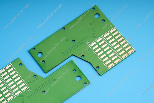
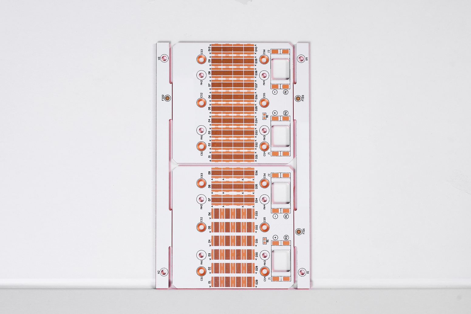
For high-current BMS designs, copper thickness and trace width should be selected according to current, temperature rise, and PCB structure. Heavy copper PCB may be useful in power battery applications. Multilayer PCB design can also help separate signal, power, and thermal paths.
How Can EBest Circuit Support BMS PCB and PCBA Projects?
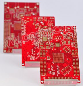
EBest Circuit supports BMS PCB and PCBA projects from prototype to production. We provide multilayer PCB fabrication, heavy copper PCB, high Tg PCB, SMT assembly, component sourcing, functional testing, and box build assembly. For battery packs, energy storage systems, power tools, e-bikes, robotics, industrial control products, and power modules, these capabilities can help engineers move from design validation to stable production.
A reliable BMS needs more than a correct schematic, it needs proper PCB layout, controlled manufacturing, careful assembly, and practical testing. EBest Circuit can support customers with PCB fabrication and PCBA services for BMS hardware that requires stable voltage sensing, strong current handling, and dependable field performance. If you have any questions about BMS PCB or high current PCB, welcome to contact us at sales@bestpcbs.com.
FAQs
How much voltage difference is normal between battery cells in a BMS?
For many lithium battery packs, a few millivolts to around 30mV at rest is usually considered normal. A difference of 30–50mV may trigger balancing in some BMS designs. A difference above 100mV should be checked carefully, especially if it appears repeatedly.
Is 30mV cell voltage difference normal?
Yes, 30mV can be normal in many battery packs, especially during charging or discharging. However, if the pack remains around 30mV or higher after resting, the BMS balancing behavior and cell condition should be checked.
Is 100mV cell imbalance bad?
A 100mV difference is not always immediately dangerous, but it is usually a warning sign. It may indicate cell aging, capacity mismatch, internal resistance difference, poor connection, or insufficient balancing. It is more serious near full charge or near the discharge cutoff.
Why does my BMS show different cell voltages?
The BMS may show different cell voltages because cells are not perfectly matched. Differences can also come from aging, temperature variation, self-discharge, poor welding, loose sense wires, or measurement error.
Why does battery voltage drop under load?
Battery voltage drops under load because current flows through internal resistance and external resistance. The drop can come from the cell, busbar, connector, cable, MOSFET, fuse, solder joint, or PCB copper path.
Can a BMS fix unbalanced cells?
A BMS can reduce moderate imbalance through balancing, but it cannot fully repair a weak or damaged cell. If one cell has much lower capacity or higher internal resistance, balancing may only hide the problem for a short time.
Does cell voltage imbalance reduce battery capacity?
Yes. In a series battery pack, the weakest cell group limits the whole pack. If one cell charges or discharges faster than others, the BMS may stop the pack early, reducing usable capacity.
What voltage difference triggers BMS balancing?
It depends on the BMS design. Some designs may start balancing around 30mV difference, while others may use different thresholds. The balancing start voltage and delta voltage should match the battery chemistry, cell capacity, and application requirements.
Why is BMS voltage different from multimeter voltage?
The BMS and multimeter may measure at different points. Current flow, wire resistance, connector drop, sampling delay, calibration tolerance, and active balancing can all create different readings.
How do I know if my BMS voltage reading is accurate?
Compare the BMS reading with a calibrated multimeter under resting conditions. Measure at the same reference points when possible. If the difference is large, check sense wires, connectors, solder joints, PCB layout, input filtering, and calibration settings.