PCB manufacturing PCB manufacturing
Home > Blog

BMS PCB

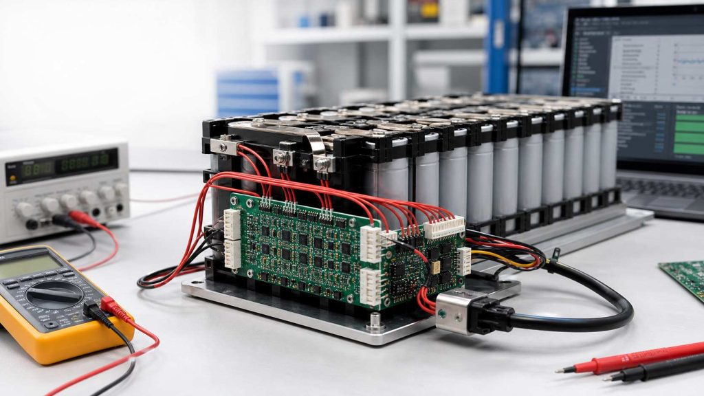
How Much Can Voltage Vary in a BMS?
Thursday, July 9th, 2026

In a BMS, small voltage variation between battery cells is normal. A well-balanced lithium battery pack may show only a few millivolts to around 30mV difference between cells at rest. A difference of 30–50mV may be enough to trigger balancing in some BMS designs, while 100mV or more should be checked carefully, especially near full charge or full discharge.

However, there is no single “safe voltage variation” number for every battery pack. The acceptable range depends on battery chemistry, cell count, state of charge, load current, temperature, cell aging, BMS measurement accuracy, and the protection settings used in the design. For example, common Li-ion cells often charge to about 4.20V per cell with a tolerance of around ±50mV, while LiFePO4 cells use a lower full-charge voltage.
How Much Can Voltage Vary in a BMS?

What Does Voltage Variation Mean in a BMS?

Voltage variation in a BMS can mean several different things. This is why many battery problems are misunderstood at the beginning.

First, it can refer to pack voltage variation. This means the total voltage of the battery pack changes during charging, discharging, resting, or under load. A 10S lithium-ion pack, for example, may move from around 42.0V when fully charged to a much lower voltage during discharge.

Second, it can refer to cell-to-cell voltage difference. This is usually the most important value inside a BMS. In a series-connected battery pack, the BMS monitors each cell group. If one cell group is higher or lower than the others, the pack may become unbalanced.

Third, voltage variation can mean voltage sag under load. When the battery provides current to a motor, inverter, heater, pump, or power module, the voltage may drop. This drop can come from cell internal resistance, busbars, connectors, MOSFETs, PCB copper resistance, and wiring.

Fourth, voltage variation can also come from measurement deviation. A BMS reading may not exactly match a multimeter reading if the two measurements are taken at different points, at different times, or under different current conditions.

So before judging whether voltage variation is safe, it is important to identify which voltage is being discussed: pack voltage, cell voltage, loaded voltage, resting voltage, or measured voltage.

How Much Can Cell Voltage Vary in a BMS?

For many lithium battery packs, a small cell voltage difference is normal. A new, well-matched pack may stay within a few millivolts when fully rested. In real use, a difference of 10–30mV is often considered normal for many packs. A difference of 30–50mV may need balancing, depending on the BMS design. A difference above 100mV is usually worth checking, especially if it appears near the top or bottom of the charge range.

A useful practical reference is shown below:

Cell Voltage DifferencePractical Meaning
0–10mVVery well balanced pack
10–30mVUsually acceptable in many lithium packs
30–50mVMay trigger balancing in some BMS designs
50–100mVNeeds attention, especially near full charge or low charge
Over 100mVPossible imbalance, weak cell, aging, or connection issue

Warm Notice:

This table should be treated as an engineering reference, not a universal standard. Some battery packs work with tighter limits, especially in electric vehicles, medical devices, robotics, and energy storage systems. Other lower-cost applications may allow wider differences, but they still need safe overvoltage and undervoltage protection.

What Is a Normal Voltage Difference Between Battery Cells?

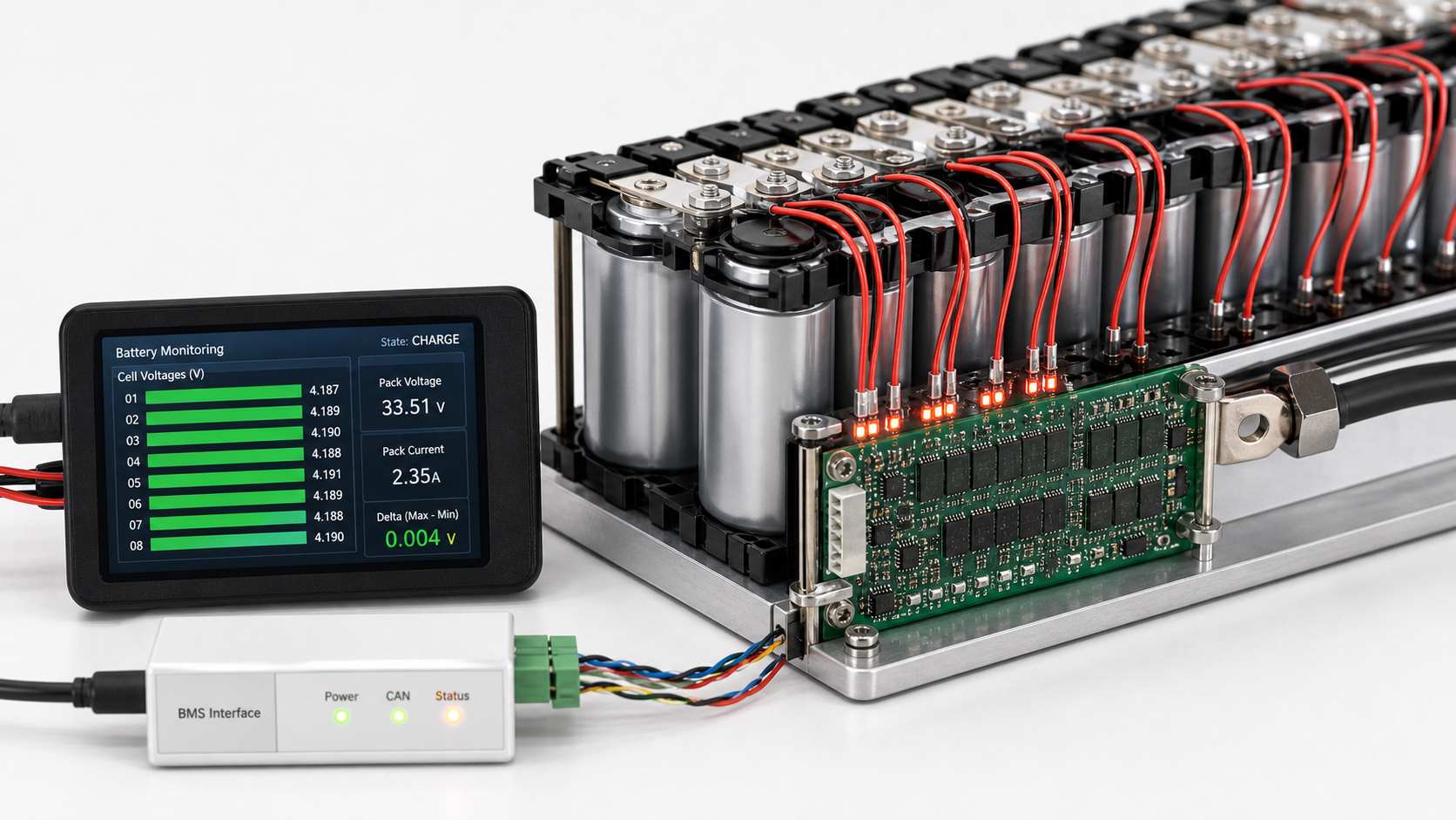
A normal voltage difference depends strongly on when the measurement is taken. A cell difference measured during high-current discharge does not have the same meaning as a cell difference measured after the battery has rested for one hour.

For a healthy lithium battery pack at rest, a small difference is expected. If all cells are similar in capacity, internal resistance, temperature, and aging condition, the cell voltages should stay close. But when the pack is charging or discharging, the difference may become larger for a short time.

The most useful time to judge cell balance is usually:

  • after the pack has rested
  • near the upper charge region
  • near the lower discharge region
  • and after several normal charge-discharge cycles

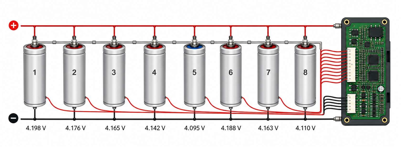
Cell imbalance becomes more serious when the same cell is always higher during charging or always lower during discharging. A weak cell often fills faster and empties faster than the others.
What Is a Normal Voltage Difference Between Battery Cells?

How Much Can Pack Voltage Vary During Charge and Discharge?

Pack voltage varies much more than cell-to-cell voltage difference. This is normal because total pack voltage follows the state of charge.

The basic formula is simple:

Pack voltage = cell voltage × number of cells in series

For a common Li-ion pack, each cell may charge to around 4.20V. Therefore, pack voltage rises as the number of series cells increases.

Battery PackSeries CellsApprox. Full Voltage for Li-ionApprox. Lower Discharge Reference
3S Li-ion3 cells12.6Varound 9.0V
4S Li-ion4 cells16.8Varound 12.0V
10S Li-ion10 cells42.0Varound 30.0V
13S Li-ion13 cells54.6Varound 39.0V
16S Li-ion16 cells67.2Varound 48.0V

These numbers are only general references. Actual protection limits should always follow the cell datasheet, battery chemistry, charger design, product safety requirements, and BMS settings.

This is why BMS design must monitor individual cells, not only total pack voltage. A 10S pack may show a normal total voltage while one cell group is already too high or too low.

How Does Battery Chemistry Affect BMS Voltage Variation?

Battery chemistry has a direct influence on voltage limits. A voltage that is normal for one chemistry may be unsafe or incorrect for another.

Battery ChemistryNominal Cell VoltageCommon Full Charge VoltageCommon Discharge Cutoff Reference
Li-ion / NMC / LCO3.6V or 3.7Varound 4.20Varound 3.0V
LiFePO43.2Varound 3.65Varound 2.5V
LTOaround 2.3Voften around 2.7–2.8Voften around 1.5–1.8V

LiFePO4 is a good example. It has a flatter voltage curve than many Li-ion chemistries. This makes voltage-based state-of-charge estimation more difficult in the middle of the discharge range. A small voltage change may represent a large capacity change, depending on where the cell is on the curve.

For EVE LiFePO4 cells, one product specification lists standard charging to 3.65V and standard discharge cutoff at 2.5V under defined test conditions. This is different from common 4.20V Li-ion cells, so the BMS thresholds must be chemistry-specific.

Why Does Voltage Drop Under Load in a BMS?

Voltage drop under load is also called voltage sag. It happens when the battery delivers current and the internal resistance of the electrical path causes a voltage loss.

Voltage sag can come from several areas:

  • Cell internal resistance
  • Busbar resistance
  • Nickel strip resistance
  • Connector resistance
  • Cable resistance
  • MOSFET on-resistance
  • Fuse resistance
  • PCB copper resistance
  • Solder joint quality
  • Temperature

At low current, the voltage drop may be small. At high current, it can become much larger. This is why electric bikes, power tools, drones, AGVs, solar energy storage systems, and industrial battery packs need careful current-path design.

Why Do Cell Voltages Become Unbalanced?

Cell voltage imbalance usually develops from small differences between cells. Even cells from the same batch are not perfectly identical. Over time, these differences can grow.

Common causes include:

  • different cell capacities,
  • different internal resistance values,
  • cell aging,
  • temperature gradient inside the pack,
  • uneven self-discharge,
  • inconsistent welding quality,
  • poor busbar contact,
  • loose sense wires,
  • inaccurate BMS voltage sensing,
  • and different current sharing in parallel groups.

In a series battery pack, the weakest cell group controls the usable capacity of the whole pack. If one cell group reaches the upper voltage limit first, the BMS may stop charging even though other cells are not fully charged. If one cell group reaches the lower voltage limit first, the BMS may stop discharging even though other cells still have energy.

How Does a BMS Balance Cell Voltage?

A BMS balances cell voltage to keep series-connected cells closer in state of charge. The two main balancing methods are passive balancing and active balancing.

Balancing TypeHow It WorksMain AdvantageCommon Limitation
Passive balancingBleeds extra energy from higher-voltage cells through resistorsSimple and cost-effectiveEnergy is dissipated as heat
Active balancingTransfers energy from higher cells to lower cells or to the packHigher efficiencyMore complex and costly

The right choice depends on pack size, current level, cost target, energy efficiency, heat control, and application requirements. For large energy storage systems and EV battery packs, active balancing may offer strong benefits. For many consumer, industrial, and backup-power products, passive balancing remains widely used.
balanced-vs-imbalanced-battery-pack

When Is BMS Voltage Variation Dangerous?

Voltage variation becomes dangerous when one or more cells move outside the safe operating area. The most serious conditions are overvoltage, undervoltage, excessive voltage difference, rapid voltage drift, and abnormal temperature rise.

You should pay attention when:

  • one cell reaches overvoltage before the others,
  • one cell drops to undervoltage much earlier than the others,
  • cell voltage difference keeps increasing after every cycle,
  • the BMS cuts off charging too early,
  • the BMS cuts off discharge too early,
  • the pack becomes hot during charge or discharge,
  • one cell voltage changes faster than the others,
  • the BMS reading differs greatly from a calibrated meter,
  • or the pack loses capacity quickly.

Why Is the BMS Voltage Reading Different From a Multimeter?

A BMS voltage reading may not match a multimeter reading exactly. This does not always mean the BMS is faulty.

Common reasons include:

  • the BMS and multimeter measure at different points,
  • current is flowing during measurement,
  • voltage drops across cables or connectors,
  • the BMS has ADC tolerance,
  • the multimeter has its own accuracy tolerance,
  • the BMS sampling rate creates a time delay,
  • balancing is active during measurement,
  • the sense wire is loose,
  • electrical noise affects the analog front end,
  • or the PCB layout introduces measurement error.

For example, measuring pack voltage at the output connector may give a different value from measuring directly at the cell terminals. If current is flowing, cable and MOSFET voltage drop can create a visible difference.

How Should BMS Voltage Limits Be Set?

BMS voltage limits should always be based on the battery cell datasheet and the product’s safety requirements. Guessing these values can reduce pack life or create safety risks.

Important voltage parameters include:

BMS ParameterWhat It Controls
Cell overvoltage protectionStops charging when one cell is too high
Cell undervoltage protectionStops discharge when one cell is too low
Pack overvoltage protectionProtects the whole pack during charging
Pack undervoltage protectionProtects the whole pack during discharge
Recovery voltageDefines when the BMS can return to normal operation
Balancing start voltageDefines when balancing is allowed to begin
Balancing delta voltageDefines how much cell difference triggers balancing
Protection delay timePrevents false triggering from short transients

For products such as e-bikes, power stations, robotics, industrial equipment, solar storage, and medical electronics, BMS parameter design should be validated under real load conditions. Bench testing at room temperature is not enough. The pack should also be tested under high load, low temperature, high temperature, charging, resting, and aging conditions.

How Does PCB Design Affect BMS Voltage Variation?

BMS voltage variation may look like a battery cell problem, but sometimes the root cause is in the PCB, wiring, or interconnection system.

A BMS PCB usually contains both high-current circuits and sensitive voltage measurement circuits. These two areas have very different design needs. The power path needs low resistance, strong copper, good thermal performance, and reliable soldering. The sensing path needs low noise, stable references, clean routing, and accurate signal transmission.

Several PCB-related issues can affect BMS voltage behavior:

  • Insufficient copper thickness for current paths
  • Narrow or long high-current traces
  • Poor MOSFET thermal layout
  • Weak solder joints
  • Unstable connectors
  • Shared ground paths
  • Noisy switching circuits near sense traces
  • Poor input filtering
  • Inaccurate test points

For high-current BMS designs, copper thickness and trace width should be selected according to current, temperature rise, and PCB structure. Heavy copper PCB may be useful in power battery applications. Multilayer PCB design can also help separate signal, power, and thermal paths.

How Can EBest Circuit Support BMS PCB and PCBA Projects?

EBest Circuit supports BMS PCB and PCBA projects from prototype to production. We provide multilayer PCB fabrication, heavy copper PCB, high Tg PCB, SMT assembly, component sourcing, functional testing, and box build assembly. For battery packs, energy storage systems, power tools, e-bikes, robotics, industrial control products, and power modules, these capabilities can help engineers move from design validation to stable production.

A reliable BMS needs more than a correct schematic, it needs proper PCB layout, controlled manufacturing, careful assembly, and practical testing. EBest Circuit can support customers with PCB fabrication and PCBA services for BMS hardware that requires stable voltage sensing, strong current handling, and dependable field performance. If you have any questions about BMS PCB or high current PCB, welcome to contact us at sales@bestpcbs.com.

FAQs

How much voltage difference is normal between battery cells in a BMS?

For many lithium battery packs, a few millivolts to around 30mV at rest is usually considered normal. A difference of 30–50mV may trigger balancing in some BMS designs. A difference above 100mV should be checked carefully, especially if it appears repeatedly.

Is 30mV cell voltage difference normal?

Yes, 30mV can be normal in many battery packs, especially during charging or discharging. However, if the pack remains around 30mV or higher after resting, the BMS balancing behavior and cell condition should be checked.

Is 100mV cell imbalance bad?

A 100mV difference is not always immediately dangerous, but it is usually a warning sign. It may indicate cell aging, capacity mismatch, internal resistance difference, poor connection, or insufficient balancing. It is more serious near full charge or near the discharge cutoff.

Why does my BMS show different cell voltages?

The BMS may show different cell voltages because cells are not perfectly matched. Differences can also come from aging, temperature variation, self-discharge, poor welding, loose sense wires, or measurement error.

Why does battery voltage drop under load?

Battery voltage drops under load because current flows through internal resistance and external resistance. The drop can come from the cell, busbar, connector, cable, MOSFET, fuse, solder joint, or PCB copper path.

Can a BMS fix unbalanced cells?

A BMS can reduce moderate imbalance through balancing, but it cannot fully repair a weak or damaged cell. If one cell has much lower capacity or higher internal resistance, balancing may only hide the problem for a short time.

Does cell voltage imbalance reduce battery capacity?

Yes. In a series battery pack, the weakest cell group limits the whole pack. If one cell charges or discharges faster than others, the BMS may stop the pack early, reducing usable capacity.

What voltage difference triggers BMS balancing?

It depends on the BMS design. Some designs may start balancing around 30mV difference, while others may use different thresholds. The balancing start voltage and delta voltage should match the battery chemistry, cell capacity, and application requirements.

Why is BMS voltage different from multimeter voltage?

The BMS and multimeter may measure at different points. Current flow, wire resistance, connector drop, sampling delay, calibration tolerance, and active balancing can all create different readings.

How do I know if my BMS voltage reading is accurate?

Compare the BMS reading with a calibrated multimeter under resting conditions. Measure at the same reference points when possible. If the difference is large, check sense wires, connectors, solder joints, PCB layout, input filtering, and calibration settings.

You may also like

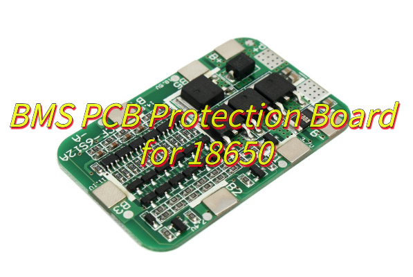
BMS PCB Protection Board for 18650​
Monday, June 30th, 2025

How BMS PCB keeps your 18650 battery pack safe and efficient?‌ This guide covers everything from wiring and design to cost-effective noise shielding and heat management for optimal BMS PCB protection.

Using 18 years of BMS PCBA technology accumulation, we will protect your battery safety!

  • Poor welding? – Nitrogen reflow + 3D SPI detection to eliminate false welding
  • Delivery delay? – Intelligent scheduling system guarantees 7-day delivery
  • Cost out of control? – Standardized process reduces 15% assembly cost
  • Poor compatibility? – Support TI/ADI/NXP and other multi-platform solution adaptation

EBest Circuit (Best Technology) Provide:

  • Integrated solution – From PCB design to finished product assembly, BMS protection board “plug and play” is realized
  • High-precision mounting – 01005 component mounting accuracy ±25μm, ensuring the stability of the sampling circuit
  • Triple test guarantee – AOI+ICT+FCT full inspection, fault interception rate increased to 99.97%
  • Flexible production – Support 1-16 layer board mixed production, 24-48 hours ultra-fast prototyping.

Let every BMS PCB become the intelligent guardian of the battery system! Contact us now: sales@bestpcbs.com.

What Is BMS PCB?

A BMS PCB (Battery Management System Printed Circuit Board) serves as the central control unit for rechargeable battery packs, ensuring safe and efficient operation. It monitors vital parameters including individual cell voltages, overall current flow, and temperature distribution across connected battery cells. When detecting potentially hazardous conditions such as overcharging, excessive discharge, or abnormal heat buildup, the system automatically disconnects the battery through integrated protection circuits to prevent permanent damage.

To maintain consistent performance, most BMS PCBs incorporate cell balancing functionality, which adjusts charge distribution among cells during operation. This process helps maximize available energy storage while extending battery lifespan. Communication capabilities allow the board to relay operational data, including state-of-charge estimates and system warnings, to connected devices through standard interfaces. The implementation varies across applications, with simpler versions managing small consumer electronics and more advanced configurations supporting high-capacity systems like electric vehicles and renewable energy storage installations.

What Is BMS PCB?

How to Wire PCB BMS?

Here’s a practical guide to wiring a BMS PCB, focusing on achieving reliability, safety, and performance:

1. Establish Accurate Cell Voltage Monitoring

  • Connect each cell voltage sense wire directly to its corresponding cell terminal within the battery pack. Keep these sense wires as short and consistent in length as feasible and route them away from high-current paths to minimize noise interference and ensure precise voltage readings by the BMS PCB.

      2. Implement Dedicated High-Current Paths

      • Use appropriately thick traces or busbars for the main battery pack positive (P+) and negative (P-) connections entering the BMS PCB. Similarly, size the discharge (B-) and charge/discharge output (C- or P-) traces adequately to safely carry their maximum expected currents without excessive voltage drop or heating.

      3. Apply Effective Grounding Strategies

      • Create a solid, low-impedance reference ground plane on the BMS PCB near the current shunt resistor. Physically separate and connect sensitive analog measurement grounds (like cell sense circuits) directly to this reference point before connecting noisy digital grounds or high-current FET grounds.

      4. Route Signal Traces Mindfully

      • Physically separate sensitive signals like cell voltage sense lines. Shield communication lines (CAN, UART, etc.) whenever possible using twisted pairs, shielded cables, or ground planes adjacent to the traces on the BMS PCB itself.

      5. Install Thermistors Securely

      • Mount temperature sensors directly onto the cell surface or module terminals where thermal monitoring is required. Route their connecting wires carefully to avoid snagging or damage and connect them securely to the designated thermistor input pins on the BMS PCB.

      6. Connect Balancing Components Efficiently

      • Link balancing resistors or FETs directly to their respective cell sense points. Ensure the balancing current paths on the BMS PCB have adequate trace width for the balancing current level without causing localized heating. Tightly group balancing components to shorten signal paths.

      7. Select and Wire Suitable Connectors

      • Choose connectors rated well above the maximum operating current and voltage, with sufficient pin density and locking mechanisms. Match wire gauges to current loads. Clearly label all connector positions for unambiguous wiring to the BMS PCB.

      8. Integrate Protective Elements

      • Install necessary fuses or circuit breakers in series with the main pack positive (P+) input path before it reaches the BMS PCB. Ensure the fuse rating aligns with system capabilities. Connect any external contactor control coils to the designated driver outputs on the BMS PCB.

      9. Verify Connections Thoroughly

      • Before applying power, meticulously check all wiring against the BMS PCB schematic and layout diagram. Use a multimeter to confirm absence of short circuits, verify correct voltage polarity at each sense point, and ensure thermistor resistances read correctly at the connector.

      How to Design BMS PCB Heat Dissipation Structure to Avoid MOSFET Hot Spot Failure?

      Here are practical approaches to design BMS PCB heat dissipation structures that effectively prevent MOSFET hot spot failures:

      • Strategic Component Placement: Position MOSFETs away from other heat-generating components and near board edges or ventilation areas. Allow sufficient spacing between devices to enable airflow and prevent thermal interference.
      • Optimized Copper Pour Layout: Use thick copper layers (≥2 oz) for power traces and create large, continuous copper areas connected to MOSFET source/drain pins. Expand these pours to maximize surface area for heat dissipation.
      • Thermal Via Implementation: Place dense arrays of thermal vias beneath MOSFET packages, connecting top-side heat sources to inner copper layers or bottom-side heatsinks. Follow manufacturer recommendations for via diameter and spacing.
      • Effective Heatsink Integration: Design PCB mounting points for clip-on or screw-attached heatsinks. Ensure flat surface areas under MOSFETs for proper thermal interface material contact when using external cooling solutions.
      • Current Distribution Balancing: Implement symmetrical layouts with identical trace lengths when using parallel MOSFETs. This prevents uneven current sharing that could cause localized overheating in individual devices.
      • Thermal Relief Pad Design: Configure solder pads with appropriate thermal relief patterns – enough to allow proper soldering while maintaining efficient heat transfer to the PCB copper.
      • Temperature Monitoring Integration: Embed temperature sensors near expected hot spots, positioned to detect actual MOSFET case temperatures rather than ambient board temperature for accurate thermal management.
      How to Design BMS PCB Heat Dissipation Structure to Avoid MOSFET Hot Spot Failure?

      How to Shield BMS PCBs from High-Voltage Noise Without Breaking the Budget?

      Cost-effective strategies to shield BMS PCBs from high-voltage noise

      Prioritize TVS Diodes for Transient Voltage Suppression

      • Implementation: Install TVS diodes at power inputs and critical signal lines (e.g., CAN bus, sensor interfaces).
      • Why: Clamps high-voltage spikes from load dumps or inductive switching, diverting excess energy to ground.
      • Cost Efficiency: Low-cost unidirectional/bidirectional TVS arrays (e.g., SMAJ series) provide robust protection without complex circuitry.

      Optimize PCB Layout for Noise Isolation

      • Ground Plane Strategy: Use dedicated ground layers for analog/digital sections. Separate high-current paths (e.g., battery cell balancing) from low-voltage sensor traces.
      • Trace Routing: Keep high-voltage traces >2mm from sensitive signals. Avoid 90-degree bends to minimize impedance discontinuities.
      • Decoupling: Place 0.1µF ceramic capacitors near every IC power pin and 10µF electrolytic capacitors at PCB entry points.

      Leverage Ferrite Beads for HF Attenuation

      • Application: Insert ferrite beads (e.g., Murata BLM series) in series with power lines to the MCU and communication modules.
      • Benefit: Dissipates high-frequency noise as heat without affecting DC power delivery.
      • Budget Tip: Use multi-layer chip inductors (e.g., 1206 size) for cost-effective EMI filtering.

      DIY Shielding with Copper Tape or Aluminum Enclosures

      • Low-Cost Enclosure: Line BMS housing with adhesive copper foil (≤$5 for 1m²) and connect to PCB ground.
      • Gap Management: Seal seams with conductive gasket tape to prevent electromagnetic leakage.
      • Alternative: Repurpose aluminum tooling plates as shields, secured with nylon screws to avoid ground loops.

      Software Filtering for Noisy Sensors

      • Algorithm: Implement a moving average or Kalman filter in BMS firmware to smooth voltage/current readings.
      • Example: Apply a 10-sample moving average to cell voltage data to reject transient spikes from motor noise.
      • Zero Hardware Cost: Leverage unused MCU flash memory to store filter coefficients.

      Isolation Techniques for Critical Nodes

      • Optocouplers: Use low-cost optoisolators (e.g., PC817) for relay drivers or charge enable signals.
      • Digital Isolators: For CAN/RS-485 interfaces, adopt cost-effective isolators like ISO7741 (under $2 in qty).
      • Galvanic Separation: Prevent ground loops by isolating high-voltage sampling circuits from the main MCU.

      What Is A BMS Protection PCB Board?

      A BMS protection PCB board is a dedicated hardware solution designed to ensure battery pack safety by monitoring critical parameters in real time. This printed circuit board tracks cell voltages, pack current, and temperature distribution while comparing these values against predefined safety thresholds. When detecting unsafe conditions like overvoltage, undervoltage, excessive current, or high temperatures, it activates protective measures through control elements such as power MOSFETs to isolate the battery. The board also incorporates cell balancing functions, state-of-charge estimation, and communication interfaces to relay system status. Its primary purpose is to provide autonomous hardware-level protection that prevents catastrophic failures while maintaining safe battery operation.

      What Is A BMS Protection PCB Board?

      How to Use PCB BMS Protection Board for 18650s?

      How to use a PCB BMS protection board for 18650 batteries:

      1. Inspect the BMS and Batteries

      • Confirm the BMS matches your 18650 cell count (e.g., 4S for four 3.7V cells in series).
      • Check battery voltage with a multimeter to ensure no cell is below 2.5V before connecting the BMS.

      2. Wire the Battery Pack

      • Connect the battery pack’s negative terminal to the BMS B- port using 16–20 AWG silicon wire.
      • Route each cell’s balance wire (B1+, B2+, etc.) to the corresponding BMS balance ports. Avoid crossing wires to prevent short circuits.

      3. Connect Charger and Load

      • Attach the charger’s negative lead to the BMS P- port and positive lead to the battery pack’s positive terminal.
      • Connect the load (e.g., device, inverter) to the same P- port and pack positive, ensuring the load’s current draw does not exceed the BMS rating.

      4. Secure and Ventilate the BMS

      • Mount the BMS using nylon standoffs to prevent contact with metallic surfaces.
      • Ensure adequate airflow around the BMS, especially if it lacks built-in heat sinks.

      5. Initial Power-Up and Testing

      • Charge the pack at 0.5A–1A initially to verify the BMS triggers overcharge protection at 4.25V per cell.
      • Discharge the pack with a low-power load (e.g., LED light) to test over-discharge cutoff at 2.5V per cell.

      6. Balance Cells Regularly

      • After 3–5 cycles, use a battery analyzer to check cell voltages. Manually discharge any cell exceeding 4.2V using a resistor.
      • Avoid full discharges to minimize voltage imbalance between cells.

      7. Monitor Temperature and Connections

      • Check for overheating near MOSFETs during high-current use. Reduce charge/discharge current if temperatures exceed 60°C.
      • Tighten terminals monthly to prevent loose connections, which can cause erratic behavior.

      8. Replace Aging Components

      • Inspect capacitors for bulging every 12 months. Replace if signs of leakage or swelling appear.
      • Upgrade to a BMS with higher current ratings if using the pack for high-drain applications (e.g., e-bikes).

      How to Choose PCB BMS Protection Board for 18650?

      Match Cell Count and Voltage

      • Choose a BMS that supports your battery pack’s configuration (e.g., 4S for four 3.7V cells in series).
      • Verify the BMS’s maximum voltage rating exceeds your pack’s fully charged voltage (e.g., 16.8V for a 4S pack).

      Check Current Ratings

      • Select a BMS with a continuous discharge current rating 20% higher than your application’s peak demand (e.g., 30A BMS for a 25A e-bike motor).
      • Ensure the charge current rating aligns with your charger’s output (e.g., 5A BMS for a 4A charger).

      Evaluate Protection Features

      • Prioritize boards with overcharge, over-discharge, over-current, and short-circuit protection.
      • Look for optional features like cell balancing, temperature sensors, and low-voltage recovery modes.

      Inspect Physical Design

      • Choose a BMS with labeled terminals and spaced-out ports to simplify wiring.
      • Prioritize models with integrated NTC thermistor ports for precise temperature monitoring.

      Verify Communication Protocols

      • For smart packs, ensure the BMS supports your device’s protocol (e.g., I2C, SMBus) or includes Bluetooth/Wi-Fi for remote monitoring.
      • Test compatibility with your charger or energy meter before finalizing.

      Review User Feedback

      • Check forums or reviews for reports of false triggers, uneven balancing, or premature MOSFET failures.
      • Avoid boards with frequent complaints about solder joint quality or inaccurate voltage readings.

      Balance Cost and Longevity

      • Avoid ultra-cheap BMS units with thin traces or generic MOSFETs, as they may fail under stress.
      • Invest in models with replaceable fuses or upgradeable firmware for future-proofing.
      How to Choose PCB BMS Protection Board for 18650?

      How to Balance Cost and Stability of BMS PCB Protection Board for 18650​?

      Here are actionable tips to balance cost and stability when selecting a PCB BMS protection board for 18650 batteries:

      Prioritize Essential Protections Over Premium Add-Ons

      • Ensure the PCB BMS protection board includes core features: overcharge, over-discharge, over-current, and short-circuit protection. These are non-negotiable for safety.
      • Avoid paying extra for advanced functions like Bluetooth monitoring or active cell balancing unless your application requires them.

      Evaluate Component Quality Carefully

      • Check for MOSFETs with mid-range current ratings (e.g., 40V/60A vs. 80A+). They offer sufficient durability for most 18650 packs without inflating costs.
      • Look for ceramic capacitors instead of electrolytic ones for better temperature stability and longer lifespan.

      Balance Current Ratings with Real-World Needs

      • Choose a PCB BMS protection board with a continuous discharge rating 10–20% above your system’s maximum draw (e.g., 25A BMS for a 20A tool). This avoids over-engineering costs.
      • Avoid boards rated far beyond your requirements, as higher current tolerance often increases price disproportionately.

      Leverage Passive Cell Balancing

      • Opt for PCB BMS protection boards with passive balancing (resistor-based) instead of active balancing (inductor-based). Passive designs are cheaper and sufficient for most 18650 applications.
      • Ensure the balancing current is ≥50mA to maintain cell health over hundreds of cycles.

      Inspect Trace Width and PCB Thickness

      • Choose a board with 2oz copper traces and a minimum thickness of 1.6mm. These specs reduce resistance and heat buildup without adding significant cost.
      • Avoid ultra-thin PCBs (e.g., 0.8mm), as they may warp or delaminate under stress.

      Check for Replaceable Fuses or Resettable PTCs

      • Some PCB BMS protection boards include user-replaceable fuses or polymer PTCs (resettable breakers). These features extend the board’s lifespan by allowing recovery from overcurrent events.
      • Compare costs: A board with a $0.50 PTC may outlast three cheaper boards without this feature.

      Review Open-Source Firmware Options

      • Select a PCB BMS protection board with publicly available firmware (e.g., via GitHub). This lets you customize protections or fix bugs without relying on the manufacturer.
      • Community-supported boards often have lower long-term maintenance costs due to shared troubleshooting resources.

      Conclusion

      In conclusion, this guide has comprehensively covered the essential aspects of BMS PCB protection boards for 18650 battery systems, from fundamental concepts to practical wiring techniques, thermal management solutions, and cost-effective noise shielding approaches. We’ve explored proper usage methods, selection criteria, and the critical balance between performance and affordability. For reliable battery management systems that prioritize both safety and efficiency, these components prove indispensable. Should you require high-quality BMS PCB solutions tailored to your specific 18650 applications, we recommend contacting EBest Circuit (Best Technology) for professional consultation and competitive pricing. Their expertise ensures optimal battery protection while meeting your technical and budgetary requirements. Welcome to contact us: sales@bestpcbs.com.

      You may also like

      How to custom BMS PCB? BMS boards
      Tuesday, January 21st, 2025

      How to custom BMS PCB? To customize BMS PCB, you need to first clarify the functional requirements and environmental adaptability requirements, then carry out circuit design, layout and wiring, and thermal management planning, and select the appropriate materials and number of layers. During the manufacturing process, high-precision printing and welding must be ensured, and its reliability must be verified through electrical testing, environmental testing, etc.

      How to custom BMS PCB? BMS boards

      What is a BMS PCB?

      A BMS PCB is the heart of a Battery Management System, designed to monitor and control the performance of a battery pack. It’s responsible for managing the charge and discharge cycles, balancing the cells, ensuring safety, and maximizing the life of the battery.

      The PCB is the physical platform that interconnects all the components of the BMS, including sensors, controllers, and power management circuitry.

      The BMS PCB typically includes several critical elements such as:

      • Voltage and current sensing components to monitor the battery’s health.
      • MOSFETs to manage the flow of current during charging and discharging.
      • Microcontrollers to process data and execute commands.
      • Protection circuits to prevent overcharging, deep discharging, and short circuits.

      This PCB ensures that the battery operates safely and efficiently, which is why customizing it to meet specific needs is so important.

      How to customize BMS PCB?

      Customizing a BMS PCB involves a detailed process that addresses various factors such as power requirements, battery specifications, and safety features.

      • Define the Requirements: Understand the application, battery specifications, and power requirements.
      • Select the Components: Based on the requirements, choose the right components, such as MOSFETs, capacitors, resistors, and microcontrollers.
      • Design the PCB Layout: The PCB layout should be designed for efficient current flow, heat dissipation, and compactness. Make sure to include clear routing for power and signal paths.
      How to custom BMS PCB? BMS boards
      • Safety Features: Include protection circuits for over-voltage, under-voltage, over-current, and thermal protection. These features help prevent damage to both the battery and the device.
      • Prototyping and Testing: After the design is complete, build a prototype and test the PCB for performance, safety, and reliability. Test for thermal performance and ensure the BMS can handle the expected load.
      • Refinement and Finalization: After testing and debugging, finalize the design, and prepare for mass production if needed.

      What is a PCM in BMS?

      PCM stands for Protection Circuit Module, a critical component of the BMS. It’s designed to monitor the battery’s voltage, current, and temperature to protect the cells from operating outside safe limits.

      If the battery’s voltage drops too low, or if it overheats, the PCM will disconnect the load or charge source, preventing potential damage.

      PCMs are typically used in simpler battery packs or in scenarios where a full-fledged BMS might not be necessary. While PCMs offer basic protection, they may not include more advanced features like cell balancing or communication capabilities.

      What does MOS mean on BMS?

      MOS stands for Metal-Oxide-Semiconductor Field-Effect Transistor, commonly referred to as MOSFETs.

      MOSFETs are crucial components in the BMS because they control the current flow between the battery cells and the device’s power system.

      MOSFETs are used in BMS to switch the charging and discharging processes on and off. They regulate the voltage and current to ensure the battery operates safely. In most BMS designs, you’ll find both P-channel and N-channel MOSFETs, each serving a different purpose for controlling the charge and discharge cycles.

      How many types of BMS are there?

      There are primarily three types of Battery Management Systems:

      • Centralized BMS: All the components, including sensors and control units, are located in a central hub.
      • Distributed BMS: Each module of the battery pack has its own BMS, which communicates with a central controller.
      • Modular BMS: Similar to distributed BMS but with a more flexible, modular approach. Each module can operate independently but can be combined with other modules for larger systems.

      The type of BMS you choose depends on the size and complexity of the battery pack, as well as the specific requirements of your application.

      Do all lithium batteries need a BMS?

      While not every lithium battery needs a BMS, most modern lithium-ion and lithium-polymer batteries do require one for safety and longevity.

      A BMS ensures that each cell is monitored and protected, preventing issues such as overcharging, over-discharging, and thermal runaway.

      How to custom BMS PCB? BMS boards

      For smaller battery packs used in devices like smartphones or laptops, a simple PCM may be sufficient.

      However, for larger battery systems, such as those used in electric vehicles, solar power storage, and large-scale energy systems, a full-featured BMS is essential for safe and reliable operation.

      What is the difference between BMS and PCB?

      While both a BMS and a PCB are integral to battery-powered systems, they serve different purposes.

      A BMS is a system that manages the battery, including monitoring the cells, balancing the charge, and protecting against unsafe conditions.

      A PCB, on the other hand, is the physical board that holds all the electronic components together, providing the connections and pathways needed for the BMS to function.

      Essentially, a BMS may include a PCB, but a PCB by itself isn’t a complete BMS.

      What is p+ and p on BMS?

      The P+ and P markings on a BMS typically refer to the positive terminal connections for the battery. These terminals are crucial for connecting the battery pack to the BMS and ensuring proper charge and discharge processes.

      The P+ is usually the main positive terminal, while P might be used to denote a secondary or more specific positive terminal, such as the one for a particular cell.

      What is b in BMS?

      The B in BMS stands for Battery. It often refers to the negative terminal connection of the battery. Just like the positive terminals (P+ and P), the B terminals are used to manage the flow of current and monitor the battery’s condition. In some cases, B- refers to the common ground or negative connection in the system.

      What does s mean in BMS?

      The S in BMS refers to Sense. This is typically associated with the voltage or current sensing points on the BMS. These sensors allow the BMS to measure the voltage across individual cells and ensure that each one operates within safe limits.

      How to custom BMS PCB? BMS boards

      By sensing the voltage, the BMS can determine if the battery is overcharged or undercharged, providing valuable data to help manage the overall health of the battery pack.

      Conclusion:

      At EBest Circuit (Best Technology), we specialize in the design and manufacture of high-quality PCBs, including custom BMS PCBs tailored to meet the specific needs of your application. Whether you’re designing a BMS for a small consumer device or a large-scale electric vehicle, contact us at sales@bestpcbs.com

      You may also like