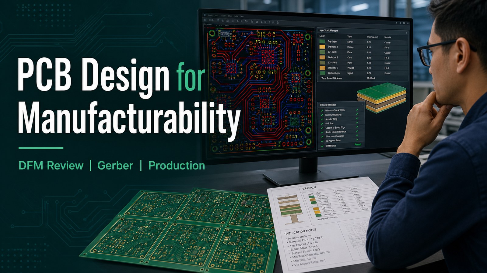
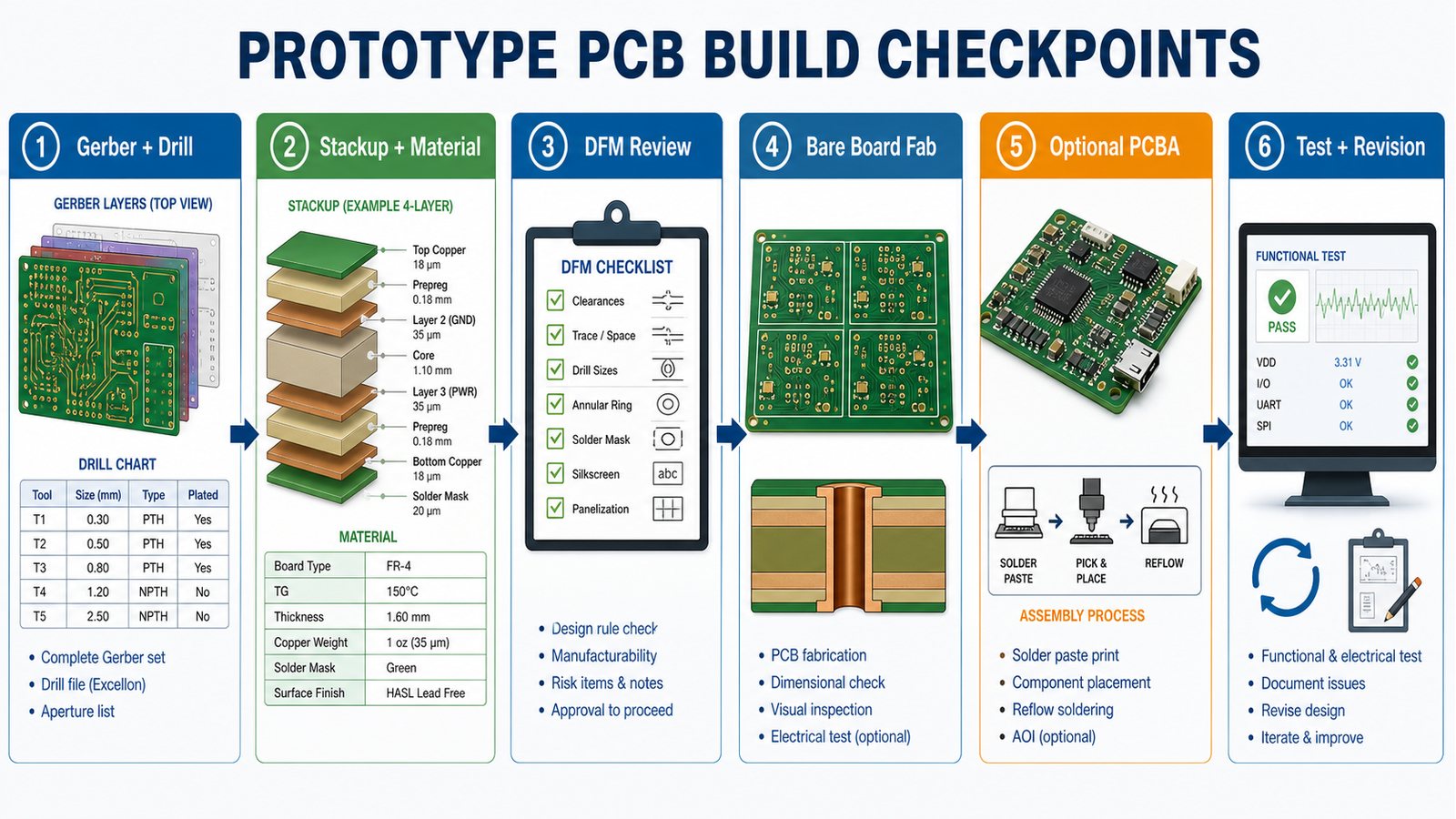
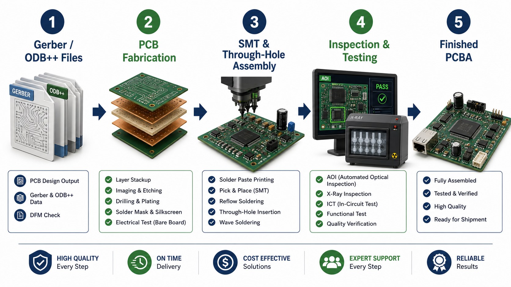
PCB design for manufacturability means checking whether a board can be fabricated, assembled, inspected and repeated before production files are released. A useful DFM review does not only look for design-rule errors. It checks whether the stackup, trace spacing, drill sizes, annular rings, copper balance, solder mask, component clearance, panelization and test access all fit the intended PCB manufacturing and PCBA process.
For buyers, DFM is a cost and schedule control step. It helps prevent a design from moving into prototype or production with hidden fabrication risk, missing files, assembly clearance problems or quote assumptions that later change the delivery plan.
Before releasing PCB files, make sure the design is ready for the way it will actually be built.
Engineering and purchasing teams often run into avoidable delays when a design is quoted before the manufacturing package is complete.
The Gerber set looks complete, but drill files, stackup notes, controlled impedance or fabrication drawings are missing.
Trace width, spacing, via drill, annular ring or copper-to-edge clearance fit the CAD rules but not the selected supplier’s process window.
Assembly files arrive after the bare-board quote, so BOM/CPL errors and component clearance issues are found late.
Panelization, fiducials, tooling rails or test access are not considered until the build is already scheduled.
A prototype passes once, but the same files are not stable enough for low volume or repeat production.
EBest Circuit reviews PCB design files with fabrication, assembly and quotation readiness in one workflow.
We review Gerber, ODB++, NC drill, stackup, fabrication drawings, material notes, surface finish and quantity before quote confirmation.
For assembled boards, we check BOM, CPL, polarity notes, assembly drawings, placement risk and test expectations with the PCB manufacturing scope.
We help buyers identify manufacturability issues early so the quotation reflects the real build, not a simplified version of the project.
We support prototype, low-volume and repeat production planning when the same design must move beyond first samples.
PCB Design for Manufacturability in One Practical Answer
PCB design for manufacturability is the review process that turns a PCB layout into a buildable production package. It checks whether the board geometry, stackup, material, drill map, copper features, solder mask, silkscreen, panelization and assembly data can move through manufacturing without avoidable holds.
Why DFM Matters Before PCB Manufacturing
DFM matters because most PCB delays are cheaper to fix before files enter production. A small clearance adjustment, stackup clarification or BOM correction can prevent re-quotes, production holds, late component surprises and repeat sample builds.
If your design is moving from layout to build planning, the PCB design and manufacturing DFM workflow is a useful companion for organizing files before supplier review.
File Package Buyers Should Prepare
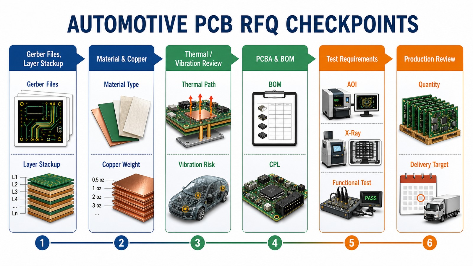
A DFM-ready RFQ package should include the files needed to quote, fabricate, assemble and inspect the board. For bare boards, send Gerber or ODB++, NC drill, stackup, fabrication drawing, material, copper weight, surface finish, board thickness, quantity and acceptance notes.
For PCBA, also send the BOM, CPL, assembly drawing, polarity notes, test instructions, programming needs and any packaging or labeling requirements. For fabrication scope review, see EBest Circuit’s PCB manufacturing capabilities.
Trace, Space, Hole and Annular Ring Checks
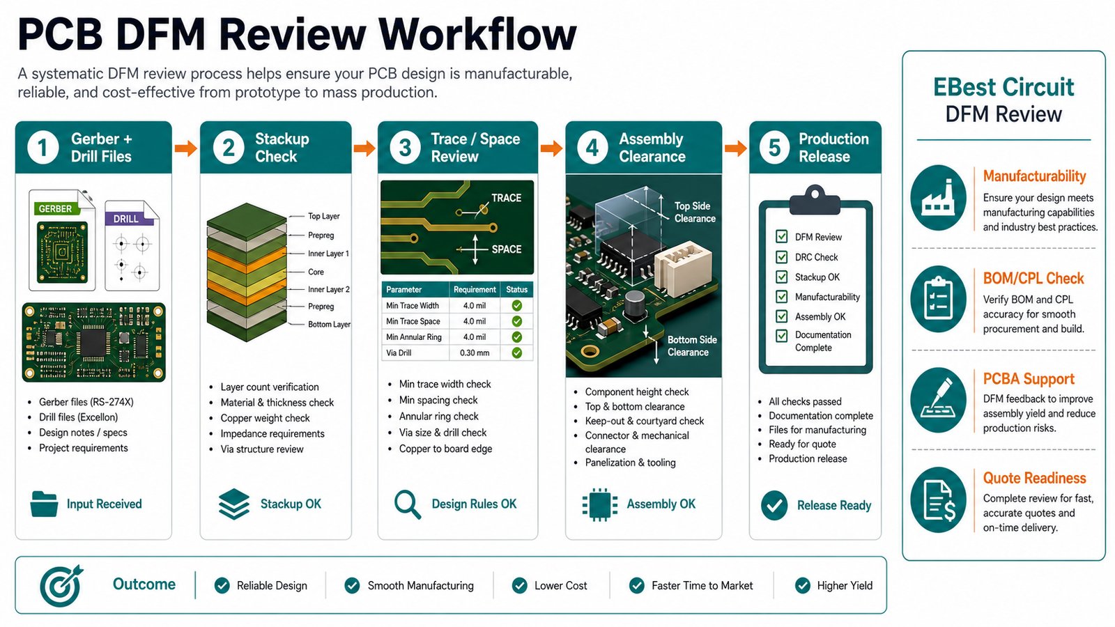
The first technical DFM check is whether copper features fit the intended process window. Review minimum trace width, trace spacing, via drill, annular ring, hole-to-copper clearance, copper-to-board-edge clearance, solder mask dams and copper balance.
DFM Area
What to Check
Why It Matters
Trace and spacing
Minimum copper width, gap and high-density areas
Prevents etching, shorting and yield risk
Drill and via
Drill size, aspect ratio, annular ring and tolerance
Controls plating reliability and registration risk
Board edge
Copper, slots, castellations and routing clearance
Prevents exposed copper and mechanical damage
Solder mask
Mask bridge, expansion and exposed pads
Supports solderability and assembly yield
Stackup, Copper and Material Checks
Stackup review confirms whether layer count, dielectric thickness, copper weight and material selection match the electrical and manufacturing goal. Controlled impedance, high-speed routing, thermal behavior and high-current areas all depend on stackup clarity before the quote is approved.
Need a DFM check before PCB production?
Send Gerber or ODB++, drill files, stackup, quantity and assembly files. EBest Circuit can review manufacturability, quote readiness and PCBA risk before you approve the build.
Mask, marking and outline details should be checked because they affect assembly, inspection and mechanical fit. Review solder mask expansion, mask slivers, exposed copper, component polarity marks, silkscreen over pads, board slots, cutouts, V-cut lines and routed edges.
Assembly Clearance and PCBA DFM Checks
PCBA DFM checks make sure the board can be assembled, inspected and tested after fabrication. Review component spacing, connector overhang, tall components, fiducials, tooling rails, stencil needs, polarity, thermal relief, keep-out areas and access for AOI, X-ray or functional test.
For turnkey builds, EBest Circuit’s PCBA and SMT assembly support can align BOM/CPL review with PCB manufacturing instead of treating assembly as a separate late-stage problem.
Testing, Panelization and Production Release
DFM is not complete until the supplier knows how the board will be panelized, inspected and released. Check electrical test, impedance test when required, AOI, X-ray for hidden solder joints, functional test access, fiducials, tooling holes, rails, breakaway tabs and packaging needs.
EBest Circuit DFM Review Workflow
EBest Circuit uses DFM review to connect engineering files with manufacturing cost, lead time and quality planning. The review starts with file completeness, then moves through stackup, copper features, material, finish, assembly data, inspection needs and quotation scope.
Use a DFM checklist before RFQ so the first supplier response is based on complete, buildable information.
Gerber or ODB++ files match the intended revision.
NC drill, stackup and fabrication drawing are included.
Material, board thickness, copper weight and surface finish are clear.
Minimum trace, spacing, via, slot and annular ring values are known.
Controlled impedance, high-current or thermal requirements are marked.
BOM, CPL and assembly notes are ready if PCBA is included.
Testing, packaging, labeling and target delivery needs are defined.
Common PCB DFM Mistakes
The most common DFM mistake is assuming that passing CAD rules means the board is ready for production. CAD rules may not reflect the selected supplier, material, assembly process, inspection method or quantity plan.
Mistake
Production Risk
Better Action
Missing stackup notes
Wrong thickness, impedance or material assumption
Confirm stackup before quote approval
Late BOM/CPL files
Assembly risk found after board quote
Send PCBA files with the RFQ
No panelization plan
Assembly handling and cost changes later
Ask supplier to review rails and fiducials
Only comparing price
Cheap quote may exclude review, testing or repeatability
Compare DFM scope and build support
Use EBest Circuit as your PCB DFM quote checkpoint.
A practical DFM review can reveal file gaps, stackup risk, assembly questions and cost drivers before production starts.
What does PCB design for manufacturability mean? It means reviewing a PCB layout and file package against real fabrication, assembly, testing and production requirements before the board is released for manufacture.
What files are needed for a PCB DFM review? Send Gerber or ODB++, NC drill, stackup, fabrication drawing, material notes, surface finish, quantity and test requirements. For assembly, also send BOM, CPL and assembly drawings.
Is DFM only needed for complex PCBs? No. Simple two-layer boards can still have drill, spacing, solder mask, silkscreen, panelization or assembly issues. DFM is most useful before the first build and before repeat production.
Can EBest Circuit review PCB and PCBA files together? Yes. EBest Circuit can review PCB fabrication files together with BOM, CPL, assembly notes and test expectations when the project includes PCBA.
Final RFQ Recommendation
Do the DFM review before the quote is treated as final. A complete review gives the buyer a clearer cost, lead time, manufacturing path and assembly risk picture before production starts.
Send your Gerber or ODB++, NC drill, stackup, fabrication drawing, BOM, CPL, quantity, material, surface finish, testing requirements and target delivery plan to sales@bestpcbs.com. EBest Circuit can review your PCB design for manufacturability and provide a practical quotation path for PCB fabrication, PCBA and production planning.
Low volume PCB manufacturing is the build stage between one-off prototypes and full production. It is used when buyers need a controlled small batch for engineering validation, pilot builds, market testing, product launch, replacement parts or specialty electronics without committing to a large production run.
The right low volume PCB partner should help with DFM review, stackup confirmation, material selection, fabrication, optional PCBA, testing, packaging and repeat-order planning. The wrong partner treats the order like a quick hobby prototype and leaves the buyer to discover production risk too late.
Before ordering a low volume PCB build, check whether the supplier can support the next production step.
Low volume PCB buyers usually face a different problem from hobby prototype buyers: the board must be affordable, but it also has to be repeatable, documented and ready for the next build.
The first quote looks cheap, but it excludes assembly, testing, components, tooling, stencil, packaging or shipping.
The supplier accepts Gerber files without checking stackup, drill, solder mask, panelization or assembly risk.
The minimum order quantity is too high for validation but too small for a stable production process.
The build moves from prototype to small batch without clear BOM/CPL control.
The buyer cannot tell whether the same supplier can support repeat production after the pilot run.
EBest Circuit supports low volume PCB manufacturing with DFM, PCBA and production planning together.
We review Gerber, ODB++, drill, stackup, fabrication drawings, BOM, CPL, quantity and test requirements before quoting.
We help buyers confirm whether the project is a prototype, low volume build, pilot run or early production order.
We support PCB fabrication and PCBA coordination, including BOM/CPL checks and inspection planning when assembly is included.
We focus on cost control, manufacturability, quality checks and repeat-order stability instead of only a low first price.
Low Volume PCB Manufacturing in One Practical Answer
Low volume PCB manufacturing produces a small, controlled batch of printed circuit boards before or instead of mass production. It is best for engineering validation, pilot builds, market testing, specialized equipment, medical electronics, industrial controls, telecom devices, LED products and replacement or service parts.
When Is Low Volume PCB Manufacturing the Right Choice?
Choose low volume manufacturing when the design is beyond a single prototype but not ready for a large production order. This stage lets buyers verify manufacturability, assembly quality, component supply, test coverage and user feedback before scaling.
Low Volume PCB Manufacturing vs Prototype PCB Builds
A prototype proves the design can work; a low volume build proves the design can be built repeatedly. Prototype orders often prioritize speed and learning. Low volume orders need clearer documentation, stable process controls, BOM accuracy and inspection evidence.
Build Stage
Typical Goal
Supplier Focus
Prototype
Validate design function
Fast DFM feedback and quick build learning
Low volume
Validate repeatability and launch readiness
Stable files, controlled cost, PCBA support and test planning
Production
Scale repeat orders
Process consistency, procurement control and long-term quality evidence
What Buyers Should Send for a Low Volume PCB Quote
A complete RFQ package helps the supplier quote the real project, not a simplified version of the board. Send Gerber or ODB++, NC drill, stackup, fabrication drawing, quantity, material, finish and acceptance notes.
If the order includes assembly, include BOM, CPL, assembly drawing, polarity notes, test instructions, programming needs and any packaging or labeling requirements. For related early-stage planning, see the prototype PCB manufacturing RFQ guide.
How EBest Circuit Handles Low Volume PCB Projects
EBest Circuit treats low volume PCB manufacturing as a bridge from first builds to repeatable production. The RFQ review checks fabrication files, assembly scope, material needs, quantity, testing and cost assumptions together.
Send your Gerber, ODB++, BOM, CPL, quantity and target schedule. EBest Circuit can review DFM risk, quote scope and small-batch production fit before you order.
DFM review is essential because small batches often expose problems that a one-off prototype missed. Check spacing, annular ring, drill size, copper balance, solder mask, silkscreen, panelization, fiducials, stackup, material and test access.
Low volume PCB manufacturing often becomes a PCBA decision once components, placement, inspection and testing are included. The supplier should review BOM, CPL, assembly drawing, polarity, substituted parts, stencil needs, AOI, X-ray needs and functional test expectations.
Cost Drivers in Low Volume PCB Manufacturing
Low volume PCB cost depends on setup effort as much as unit price. Tooling, material, panelization, stencil, component sourcing, test fixtures, inspection, packaging and shipping can matter more than the bare-board price.
Cost Factor
Why It Changes Price
Buyer Action
Quantity
Setup cost is spread across fewer units
Ask for price breaks at realistic quantities
Board complexity
Layer count, spacing, vias and finish affect process risk
Request DFM feedback before approval
Assembly
BOM sourcing, placement, inspection and test add cost
Send BOM/CPL early
Testing
Functional or fixture testing may need preparation
Define acceptance criteria
Repeat orders
Stable files can reduce future cost and delay
Control revisions and documentation
MOQ, Lead Time and Repeat Production Planning
The best low volume supplier should explain MOQ and lead time by build stage. A buyer may need 10 boards for validation, 50 for a pilot run and 200 for launch inventory. The supplier should help plan these steps without forcing an oversized first order.
Quality checks should match the board type and order risk. Bare boards may need electrical test and visual inspection. Assemblies may need AOI, X-ray for hidden solder joints, programming, first article review and functional testing.
Common Low Volume PCB Sourcing Mistakes
The biggest mistake is comparing suppliers only by the first visible unit price. A low quote can become expensive if the supplier cannot support DFM feedback, BOM control, PCBA testing, repeat orders or clear delivery planning.
Use EBest Circuit as your low volume quote benchmark.
A second quote can help you compare manufacturability, PCBA scope, testing, MOQ and repeat-order planning before committing to a supplier.
Compare cost, DFM, PCBA, testing and repeat production before approval.
Low Volume PCB Manufacturing FAQ
What is low volume PCB manufacturing? It is a controlled small-batch PCB build used after prototypes or for specialty products that do not require mass production.
Is low volume PCB manufacturing the same as prototype PCB manufacturing? No. Prototype builds focus on learning and validation. Low volume builds focus on repeatability, documentation, PCBA readiness, quality checks and launch planning.
What files are needed for a low volume PCB quote? Send Gerber or ODB++, drill files, fabrication drawing, stackup, quantity, material and surface finish. For PCBA, also send BOM, CPL, assembly drawing and test notes.
Can EBest Circuit support low volume PCB assembly? Yes. EBest Circuit can review fabrication files, BOM, CPL, DFM risk, assembly scope, testing and repeat-order planning for low volume PCB and PCBA projects.
Final RFQ Recommendation
Choose a low volume PCB manufacturer that can help you move from prototype learning to repeatable production. The right supplier gives clear DFM feedback, understands PCBA scope, explains cost and MOQ, and prepares the build for the next order.
Send your Gerber or ODB++, drill files, fabrication drawing, BOM, CPL, quantity, materials, surface finish, testing requirements and target delivery plan to sales@bestpcbs.com. EBest Circuit can review your low volume PCB manufacturing requirements and provide a practical quotation path for PCB fabrication, PCBA and small-batch production.
A custom PCB manufacturer should do more than make a board from Gerber files. The right partner checks stackup, materials, copper weight, drill data, surface finish, solder mask, panelization, assembly needs, testing requirements and quote assumptions before production starts.
For buyers, the real decision is not simply which factory can produce the lowest unit price. It is whether the manufacturer can turn your design files into reliable boards with the right manufacturing route, clear DFM feedback, stable quality controls and enough support for prototype, small-batch or production orders.
Before choosing a custom PCB manufacturer, check whether your quote package is truly build-ready.
Custom PCB orders often fail at the handoff between design, quotation and production. Buyers should check these risks early:
The supplier quotes a standard board even though the design needs special material, controlled impedance, heavy copper, HDI, flex, rigid-flex, metal core or ceramic review.
The Gerber, drill, stackup and fabrication drawing do not describe the same board.
The quote excludes assembly, BOM review, CPL data, testing, programming, conformal coating or packaging requirements that affect the real project cost.
The manufacturer accepts files without flagging spacing, annular ring, solder mask, copper balance, panelization or tolerance risks.
The buyer compares suppliers only by unit price and misses quality evidence, communication speed and engineering support.
EBest Circuit supports custom PCB projects with DFM review, manufacturing and optional PCBA coordination.
We review Gerber, ODB++, drill files, stackup, fabrication drawings, BOM and CPL files when the project requires a complete PCB or PCBA quotation.
We help buyers confirm material, copper, surface finish, board thickness, impedance, solder mask, panelization and testing requirements before production release.
We support custom discussions across FR4, HDI, heavy copper, metal core, ceramic, flex and rigid-flex PCB categories when the files need project-specific confirmation.
We keep the RFQ discussion focused on build risk, quality controls and realistic project scope instead of only a unit-price comparison.
Custom PCB Manufacturer in One Practical Answer
A custom PCB manufacturer builds boards to project-specific files, materials, dimensions, stackups and quality requirements rather than a fixed catalog design. The manufacturer should review whether the design can be fabricated, assembled, inspected and delivered under the requested conditions.
This article is written for engineers, sourcing teams and product teams comparing custom printed circuit board manufacturers for prototypes, engineering builds, low-volume production or supplier qualification.
When Do You Need a Custom PCB Manufacturer Instead of a Standard PCB Order?
You need a custom PCB manufacturer when the board has requirements that a simple online quote form cannot fully judge. Examples include tight spacing, high layer count, impedance control, unusual thickness, heavy copper, RF laminate, thermal substrate, bend areas, assembly constraints or specific inspection requirements.
If your board is a basic two-layer FR4 prototype, a simple quote tool may be enough. If the board affects heat, signal integrity, fit, vibration, enclosure assembly, compliance documentation or field reliability, the manufacturer should review the files before price becomes the only decision.
What Buyers Should Check Before Sending Files
The best supplier comparison starts with a clean file package and a clear definition of what must be built. A manufacturer cannot quote accurately if the board data, material request, finished thickness, copper weight, surface finish and assembly scope are incomplete or contradictory.
Buyer Check
Why It Matters
What to Send
Board data
Defines the physical circuit
Gerber or ODB++, drill, outline and fab notes
Stackup
Affects impedance, thickness, lamination and cost
Layer order, dielectric targets and copper weight
Material
Controls thermal, RF, flex or reliability behavior
FR4 grade or special material request
Assembly scope
Changes BOM, CPL, stencil, inspection and testing
BOM, CPL, assembly drawing and test notes
Acceptance criteria
Reduces disputes after delivery
IPC class, inspection needs and special notes
How EBest Circuit Supports Custom PCB Manufacturing Projects
EBest Circuit can review custom PCB projects from the manufacturing route through optional PCBA support. The useful starting point is a complete RFQ package, not a vague board description.
For broader capability context, buyers can review EBest Circuit’s PCB manufacturing capabilities. If a project needs assembly, the PCBA and SMT assembly support page helps connect fabrication with component mounting and production planning.
Specifications a Custom PCB Manufacturer Must Confirm
A reliable custom PCB quote should confirm the board specifications that affect manufacturability, cost and risk. At minimum, the discussion should cover layer count, finished thickness, copper weight, minimum trace/space, minimum finished hole, solder mask, silkscreen, surface finish, impedance and panelization.
Some specifications are standard for one factory but special for another. Treat special materials, unusual copper, tight tolerance, HDI, metal core, ceramic, flex or rigid-flex requirements as project-confirmation items rather than assumptions.
Prototype, Small Batch and Production Fit
The right custom PCB manufacturer should match the order stage: prototype, engineering validation, small batch or production. Prototype builds usually prioritize DFM feedback and fast learning, while production builds need stable documentation, repeatable inspection and clear change control.
Buyers should ask whether the quote supports only bare boards or also future assembly, test fixtures, packaging and repeat ordering. A low prototype price can become expensive if the supplier cannot support the next build stage.
Need a custom PCB quote checked before production?
Send Gerber or ODB++, drill, stackup, drawing, quantity and any assembly notes. EBest Circuit can review the build risk and quote scope before you commit.
Gerber/ODB++ | Drill | Stackup | Drawing | BOM/CPL if assembly is needed
Materials, Stackup and Copper Choices
Material, stackup and copper decisions should be confirmed before comparing supplier prices. FR4 remains common for many boards, while special projects may require high Tg FR4, RF laminate, aluminum, copper base, ceramic, flex or rigid-flex structures.
For FR4-related project planning, see EBest Circuit’s FR4 PCB material options. For any special material or tight process requirement, the safest wording is project confirmation: send the files and ask the manufacturer to verify whether the requested construction is standard, special or not recommended.
DFM Review Before Custom PCB Fabrication
DFM review catches manufacturing risk before CAM release, procurement and production scheduling. It should check spacing, annular ring, drill aspect ratio, copper balance, solder mask bridge, silkscreen clearance, board outline, panel rail, fiducials and test access.
A good DFM review does not replace the engineer’s design responsibility. It helps identify file conflicts and production risks early enough to revise the layout, change a material assumption or clarify a tolerance before the order is released. For a connected view of design release and production planning, see the PCB design and manufacturing workflow.
PCBA, BOM and Component Sourcing Support
If the finished product needs assembly, the custom PCB quote should include PCBA assumptions early. Bare-board fabrication and assembly are connected by pad design, solder mask, stencil openings, component availability, CPL accuracy, inspection method and test requirements.
When a project includes assembly, ask the manufacturer to review BOM, CPL, assembly drawing, polarity notes, special components, programming and functional test expectations together with the bare board files.
Quality, Inspection and Testing Evidence
Quality evidence matters more than broad claims such as “high quality” or “best manufacturer.” Ask what inspection steps apply to your board type: electrical test, AOI, X-ray for hidden solder joints, impedance report, first article review, final visual inspection or functional test when the project requires it.
The exact evidence should match the order. A simple bare board does not need the same proof package as a high-density assembly, and a prototype may need different documentation than a repeat production run.
Cost Drivers in a Custom PCB Quote
Custom PCB cost changes when the design requires more material control, process complexity, inspection effort or assembly coordination. Main drivers include layer count, board size, material, copper weight, minimum trace/space, finished hole size, surface finish, impedance, routing, quantity, testing and PCBA scope.
Do not compare suppliers only by the first quoted unit price. Compare what is included, what is excluded, what requires engineering confirmation and what happens if files need revision after DFM review.
A complete RFQ package reduces quote delay and prevents mismatched assumptions. Send the manufacturer enough information to identify the board, build route, inspection needs and commercial scope.
Gerber or ODB++ files and NC drill data.
Fabrication drawing with board thickness, copper, finish, tolerance and notes.
Stackup and impedance targets when required.
Quantity, target date and prototype or production stage.
BOM, CPL, assembly drawing and test plan if PCBA is included.
Special material, thermal, high-current, flex, rigid-flex, ceramic or metal-core requirements.
Red Flags When Comparing Custom PCB Manufacturers
Supplier red flags usually appear before production if buyers ask the right questions. Be careful when a manufacturer quotes without checking files, gives a very low price with unclear exclusions, avoids DFM discussion, cannot explain inspection steps or pushes all responsibility back to the buyer after file upload.
Price, speed, location and past supplier experience are useful comparison points, but the final decision should still depend on the board’s engineering risk and the supplier’s ability to support your exact build.
Add EBest Circuit to your custom PCB RFQ shortlist.
Let our team review the files, quote assumptions and assembly needs so you can compare suppliers on manufacturability, quality control and real project scope.
The final supplier decision should be based on build fit, evidence and communication clarity. Before approving a custom PCB manufacturer, ask direct questions that reveal whether the supplier understands your project.
Which specifications are standard, special or need engineering confirmation?
What DFM issues should be corrected before production?
Which material, copper and surface finish options fit the application?
What inspection or test evidence will be supplied?
Does the quote include only bare boards, or also assembly, BOM review and testing?
What information is still missing from the RFQ package?
Custom PCB Manufacturer FAQ
What is a custom PCB manufacturer? A custom PCB manufacturer builds printed circuit boards from project-specific design files, materials, dimensions, stackups and production requirements. The supplier should confirm manufacturability before fabrication.
Is a custom PCB manufacturer different from a PCB maker? Sometimes the terms overlap. In buying decisions, a custom PCB manufacturer usually implies stronger file review, process confirmation, material choice, quality control and project support than a simple hobby PCB maker.
What files are needed for a custom PCB quote? Send Gerber or ODB++, NC drill, fabrication drawing, stackup, quantity and special requirements. For assembly, also send BOM, CPL, assembly drawing, test notes and programming requirements if applicable.
Can a custom PCB manufacturer also assemble the board? Some manufacturers can coordinate PCBA, while others only fabricate bare boards. Confirm BOM review, CPL review, SMT, through-hole, inspection and testing scope before comparing quotes.
Final Recommendation
Choose a custom PCB manufacturer that can prove fit for your board, not just quote the lowest price. The strongest RFQ process starts with complete files, clear specifications, DFM review, quality evidence and a supplier that can support the project stage you are actually building.
Send your Gerber or ODB++, drill files, stackup, fabrication drawing, quantity, target schedule and BOM/CPL if assembly is needed to sales@bestpcbs.com. EBest Circuit can review your custom PCB manufacturing requirements and provide a practical quotation path for bare boards, PCBA or build-ready projects.
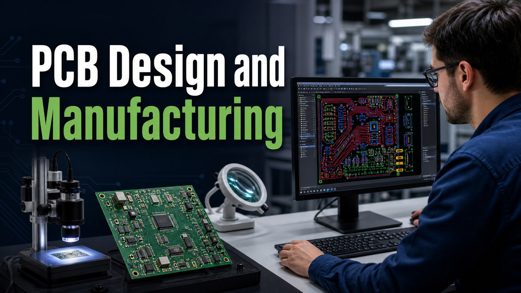
PCB design and manufacturing should be planned as one workflow, not two separate jobs. A board layout that looks complete in CAD can still fail manufacturing review if the stackup, copper, spacing, drill, solder mask, panelization, assembly access or test points are not checked before release.
For buyers and engineers, the safest path is simple: design the circuit, review the board for manufacturability, export complete files, then quote fabrication and assembly with the same technical assumptions. EBest Circuit helps customers connect DFM review, bare board production and optional PCBA so fewer problems move from design files into production.
Is your PCB design ready for manufacturing, or only ready for export?
Many projects reach RFQ stage with files that look finished but still hide production risk:
Trace spacing, drill size or annular ring is too aggressive for the selected copper weight.
The stackup does not match the requested material, board thickness or impedance target.
Silkscreen, solder mask openings or component courtyards create assembly problems.
Panelization, fiducials and test points are missing, so manufacturing and assembly teams must guess.
The supplier quotes only the bare board while BOM, CPL and testing needs are handled too late.
EBest Circuit reviews design files through a manufacturing and assembly lens.
We check Gerber, drill, drawing, stackup, copper, solder mask and surface finish before production release.
We flag manufacturability risks that can affect fabrication, SMT assembly, through-hole assembly or testing.
We support FR4, HDI, heavy copper, metal core, ceramic, flex and rigid-flex project discussions when files require more than standard review.
We can quote bare boards and PCBA together when the project needs BOM, CPL and assembly drawing review.
PCB Design and Manufacturing in One Practical Answer
PCB design defines the circuit layout, while PCB manufacturing turns that layout into a physical board; the two must be checked together through DFM review. Good design-for-manufacturing work reduces redesign, quote changes, production delay and assembly risk.
Why Design Files Fail at Manufacturing Stage
Design files usually fail because electrical layout choices were not checked against real fabrication limits. Common examples include too-small vias, narrow solder mask bridges, copper imbalance, unclear board outline, missing drill tables and incomplete fabrication notes.
A useful RFQ package tells the manufacturer not only what the circuit is, but how it should be built, finished, inspected and assembled.
DFM Review Before PCB Manufacturing
DFM review checks whether a PCB layout can be built reliably before CAM work and production begin. It should cover stackup, material, copper, minimum trace and space, hole type, annular ring, solder mask, silkscreen, outline, panelization and test access.
Stackup, laminate and copper should be locked before the buyer compares prices. FR4 material may use low Tg, mid Tg or high Tg options, while special projects may need Rogers, PTFE, ceramic, aluminum or other materials. Copper weight affects spacing, heat rise, plating, etching and cost.
For FR4 project context, see the FR4 PCB capability page.
Layout Checks That Protect Fabrication
The most important fabrication checks are trace width, spacing, drill size, annular ring, copper-to-edge clearance and solder mask bridge. These details decide whether the board can be built as standard or needs special confirmation.
Design Item
Manufacturing Risk
Buyer Action
Trace / spacing
Etching or solder bridge risk
Match rules to copper weight
Drill / pad
Weak plated hole or breakout
Check finished hole and annular ring
Board outline
Routing, V-cut or enclosure fit issue
Send mechanical drawing
Solder mask
Assembly yield risk
Review openings and bridges
Panelization
Cost and handling changes
Confirm rail, fiducial and breakaway needs
Need a DFM check before PCB manufacturing?
Send Gerber, drill, stackup, drawing, quantity and assembly notes. EBest Circuit can review the files before quote and production release.
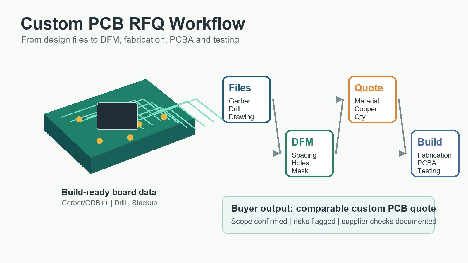
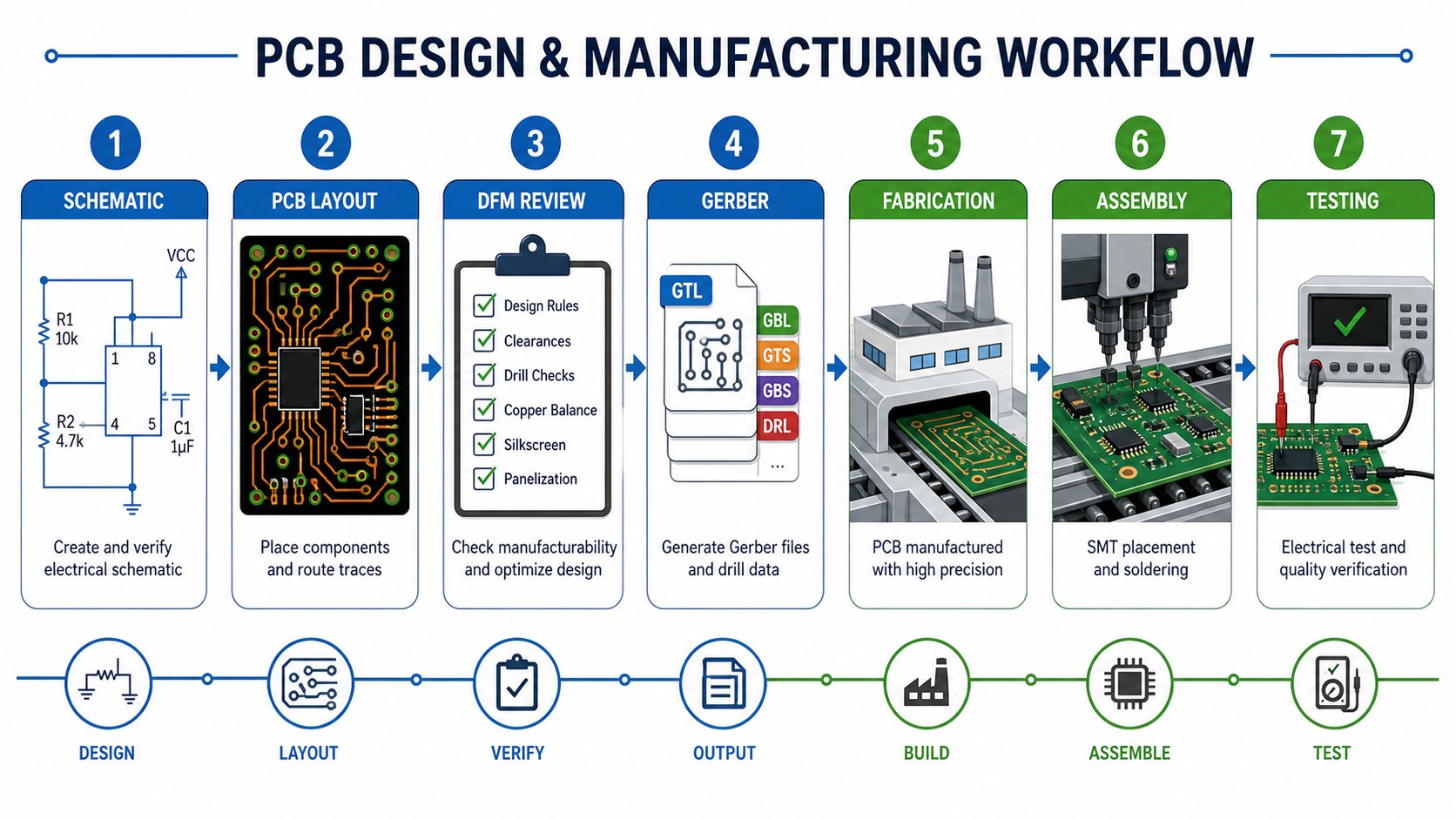
A practical PCB workflow connects schematic, layout, DFM, Gerber files, fabrication, assembly and testing.
Gerber, Drill, Drawing and BOM Package
A complete file package reduces quote changes and manufacturing questions. For bare boards, send Gerber or ODB++, NC drill, drawing, stackup, material, copper, finish, quantity and test requirements. For assembly, add BOM, CPL, assembly drawing and approved substitutions.
PCB Fabrication Process After Design Release
After release, fabrication moves through CAM review, material preparation, imaging, drilling, plating, etching, solder mask, surface finish, profiling, inspection and electrical test. The cleaner the design package is, the fewer decisions need to be corrected during CAM.
Assembly planning should start during layout, not after bare boards arrive. Component spacing, polarity marks, fiducials, test pads, panel rails and connector orientation all affect SMT and through-hole production.
If your project needs turnkey support, EBest Circuit can review fabrication data together with BOM and CPL. See our PCBA service.
Testing and Quality Checks
Testing confirms whether the design intent survived manufacturing and assembly. Bare boards may need electrical test for opens and shorts. Assemblies may need AOI, functional testing, programming, inspection reports or project-specific test fixtures.
Cost Drivers From Design to Manufacturing
Cost is shaped by design choices before the RFQ is sent. Layer count, board size, material, copper weight, surface finish, drill count, tolerance, impedance, solder mask, test method, assembly complexity and quantity all affect the final quote.
When to Move From Two Layers to Multilayer
Move to multilayer PCB when routing density, signal return, power integrity or impedance control cannot be handled safely on one or two copper layers. Staying with too few layers can create more cost through redesign and debugging than the stackup saves.
Supplier Questions Before Sending the Order
Ask questions that reveal whether the supplier can connect design review with real production.
Can you review DFM before formal production release?
Which design rules change with copper weight and surface finish?
Can you quote bare PCB and PCBA from the same file package?
What files are missing for a reliable manufacturing quote?
Will you flag assembly and testing risks before boards are built?
RFQ Checklist for PCB Design and Manufacturing
The RFQ should include enough information for engineering review, not only price calculation.
Gerber or ODB++ files
NC drill file and fabrication drawing
Stackup, material, board thickness and copper weight
Surface finish, solder mask and silkscreen notes
Quantity, target schedule and testing requirements
BOM, CPL and assembly drawing if PCBA is needed
FAQ About PCB Design and Manufacturing
These questions help buyers connect layout decisions with manufacturing results.
What is PCB design and manufacturing?
PCB design creates the circuit layout, and PCB manufacturing fabricates that design into a physical board through material preparation, drilling, plating, etching, solder mask, finish and test.
Why is DFM important before PCB manufacturing?
DFM review finds layout and file issues before production, reducing redesign, delay, quote changes and assembly risk.
Can EBest Circuit review my PCB design before quote?
Yes. Send Gerber, drill, drawing, stackup and project notes, and EBest Circuit can review the file package before preparing the manufacturing scope.
Can PCB design and assembly be reviewed together?
Yes. When PCBA is required, send BOM, CPL and assembly drawings with the PCB files so fabrication and assembly risks can be checked together.
Final Recommendation
Treat PCB design and manufacturing as one connected engineering path. The best time to control cost, schedule and quality is before files enter production, when DFM, material, copper, drill, finish, assembly and testing can still be aligned.
To review a PCB design and manufacturing project with EBest Circuit, send Gerber or ODB++, NC drill, fabrication drawing, stackup, material, copper, finish, quantity, target schedule and any BOM/CPL files to sales@bestpcbs.com. Our team will check manufacturability and prepare a practical quote scope.
Double layer PCB manufacturing builds a printed circuit board with copper circuitry on both sides of an insulating core, connected by plated through holes. It is often the best choice when a single-sided board cannot route the circuit cleanly, but the project does not yet need the cost, stackup control or density of a multilayer PCB.
For buyers, the real decision is not only whether the board has two copper layers. The safer question is whether your manufacturer can review the Gerber data, copper weight, drill file, annular ring, solder mask, surface finish, test method and assembly needs before fabrication starts. That review is where many two-layer boards either become easy to build or quietly turn into delay, rework and cost.
Is your double layer PCB order getting stuck before production?
Many two-layer boards look simple on the purchase order, but the issues usually appear inside the fabrication files:
Through-hole pads are too small for the drill tolerance, leaving weak annular rings after plating.
Trace width and spacing are copied from a prototype tool without checking the finished copper weight.
The stackup does not leave enough board thickness, copper balance or mechanical margin for the enclosure.
Solder mask openings, bridges and silkscreen markings are not matched to the assembly process.
The RFQ only asks for a unit price, so the supplier does not review test points, panelization or PCBA risk early enough.
EBest Circuit helps buyers turn a two-layer PCB file into a build-ready order.
We review Gerber, drill, drawing and stackup details before production release.
We check copper weight, hole plating, solder mask bridge, outline and finish choices against manufacturability.
We support bare board fabrication and optional PCBA so layout, fabrication and assembly risks can be handled together.
We help buyers normalize quotes by board thickness, finish, test method, panelization and order quantity instead of comparing unit price alone.
We keep the project discussion practical: what can be built as standard, what needs confirmation, and what should be corrected before the order starts.
Double Layer PCB Manufacturing in One Practical Answer
Double layer PCB manufacturing is the process of making a board with top and bottom copper layers connected by plated through holes. It is used for control boards, power interfaces, LED drivers, sensor boards, industrial electronics, consumer products and many PCBA projects where routing on one side is not enough.
A two-layer PCB normally gives more routing freedom than a single-sided board, better grounding options, shorter jumper paths and easier component placement. Compared with multilayer PCB manufacturing, it usually keeps the stackup simpler and the cost easier to control.
When a Two-Layer PCB Is the Right Build
A two-layer PCB is right when the design needs routing on both sides but does not require controlled multilayer power planes or very high density. It is a common fit for moderate-density components, connectors on both sides, low-to-medium speed signals, simple power paths and production boards that need reliable plated vias.
If your board has dense BGA escape, strict impedance control, high-speed interfaces or multiple isolated power domains, a multilayer stackup may be safer. If the circuit is very simple and one side can route cleanly, a single-sided board may still be enough. The best choice comes from routing, copper, assembly and test requirements together.
What Buyers Need to Control Before Fabrication
The most important buyer controls are copper weight, minimum trace and spacing, hole size, annular ring, board thickness, finish and test coverage. These items decide whether a two-layer board can be produced as a standard order or needs engineering confirmation.
RFQ Item
Why It Matters
What to Send
Copper weight
Affects trace width, heat rise, etching and price
Finished copper requirement for each side
Drill file
Controls plated through holes and component fit
NC drill file plus finished hole notes
Board thickness
Affects rigidity, connector fit and V-cut planning
Drawing or stackup note
Surface finish
Affects soldering, storage and contact reliability
OSP, HASL, ENIG or other finish choice
Testing
Confirms opens, shorts and production reliability
Electrical test and special inspection needs
How EBest Circuit Reviews a Two-Layer PCB Order
EBest Circuit reviews a two-layer PCB order by connecting the drawing, Gerber, drill data, copper, finish and assembly plan before quoting. This avoids a quote that looks attractive but misses the details that later change production cost or yield risk.
For a typical order, we check whether the design fits the requested material, whether copper and spacing are realistic, whether the drill and pad design support reliable plating, whether panelization will affect outline quality, and whether the finished board can support the assembly process.
Ready to quote a double layer PCB?
Send Gerber, NC drill, drawing, copper weight, finish, quantity and assembly notes. EBest Circuit will review the files before preparing a practical RFQ response.
A double layer PCB stackup normally places copper on both sides of an FR4 core, with plated holes joining the two copper layers. This structure gives the designer more options for routing signals, distributing power and creating return paths.
For low-speed control electronics, one side may carry most routing while the other side supports power and ground paths. For power or LED circuits, copper width, heat path and via placement become more important. For assembly-heavy designs, component placement and test access may matter more than the copper layers themselves.
FR4 Materials, Tg Options and Copper Weight
FR4 material and copper weight should be selected before price comparison, because both change how the board is built. EBest Circuit capability records include FR4 low Tg, mid Tg, high Tg and special material options, and list FR4 high-Tg layer capability from 1-10 layers as a general range with special review for higher layer counts.
For copper, the capability records list FR4 inner copper from HOZ-5OZ as general capability and 5-20OZ as special review; FR4 outer copper is listed from 1OZ-5OZ as general capability and 5-20OZ as special review. A two-layer board with heavy copper should therefore be checked for spacing, etching, solder mask bridge and heat requirements before order release.
Board Thickness, Panel Size and Finish Choices
Board thickness and surface finish should be matched to soldering, mechanical fit and expected handling. Capability records list common processed thickness ranges by finish, including OSP, ENIG, immersion silver, immersion tin and ENEPIG from 0.4-3.5 mm, and HASL from 0.6-3.5 mm. Boards outside the common range need project confirmation.
Finish choice should not be made only by habit. OSP can suit cost-sensitive soldering projects. HASL may fit many conventional through-hole or hand-soldered boards. ENIG is often chosen when flat pads, storage or fine assembly behavior matter. The right finish depends on assembly, storage, contact needs and cost.
Line Width, Spacing, Drill and Annular Ring Checks
Two-layer boards often fail manufacturability review at trace spacing, drill size or annular ring, not at the layer count itself. EBest Circuit capability data lists example FR4 line and space capability such as 4/4 mil general and 3/3 mil special for common copper examples, but the final check depends on copper thickness, board finish and design context.
For plated through holes, do not compare only the nominal drill diameter. The finished hole, plating allowance, pad size, annular ring and tolerance all need to work together. If the pad is too small, the board may pass a visual check but still carry long-term reliability risk.
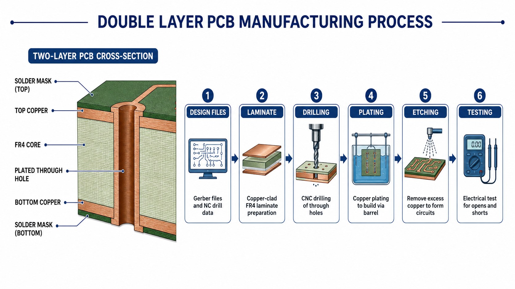
Double layer PCB manufacturing connects stackup, drilling, plating, etching and electrical testing into one build path.
Double Layer PCB Manufacturing Process
The core process includes file review, laminate preparation, drilling, copper plating, imaging, etching, solder mask, surface finish, routing and electrical test. The process is simple to describe, but each step depends on the files and requirements supplied at RFQ stage.
File review: Gerber, NC drill, drawing, stackup, quantity and finish are checked.
Laminate preparation: FR4 copper-clad material is selected and prepared.
Drilling: through holes, mounting holes and slots are drilled according to the NC file.
Plating: copper is deposited in through holes to connect top and bottom layers.
Imaging and etching: unwanted copper is removed to form the circuit pattern.
Solder mask and legend: mask openings and silkscreen are applied and checked.
Surface finish: pads receive OSP, HASL, ENIG or another specified finish.
Routing and test: boards are profiled, inspected and electrically tested.
Plated Through Hole Quality and Via Reliability
Plated through hole quality is one of the most important reliability checks in double layer PCB manufacturing. Every signal or power path that moves from top to bottom depends on drilled hole quality, plating coverage and pad design.
Buyers should identify high-current vias, connector holes, thermal vias and mechanically stressed holes in the drawing or notes. These areas may need larger pads, stronger copper, better test coverage or a DFM correction before manufacturing.
Solder Mask, Silkscreen and Surface Finish Decisions
Solder mask and surface finish affect assembly reliability as much as board appearance. The solder mask must leave enough bridge between pads, avoid unwanted exposed copper and match the assembly process. Silkscreen should remain readable without crossing pads or tight components.
EBest Circuit capability data lists solder mask color options and common surface finishes including OSP, HASL, ENIG, immersion silver, immersion tin, ENEPIG and hard gold fingers. The final finish should be chosen by soldering method, storage life, pad flatness and contact needs.
Cost Drivers in Two-Layer PCB Manufacturing
The main cost drivers are material, board size, copper weight, thickness, finish, drill count, tolerance, test coverage, panelization and quantity. A low unit price is not useful if it leaves out electrical testing, special finish, assembly support or engineering review.
Cost Factor
Typical Impact
Buyer Check
Board size
Larger panels consume more laminate
Confirm dimensions and panel quantity
Copper weight
Higher copper affects etching and spacing
State finished copper clearly
Surface finish
ENIG and special finishes usually change cost
Choose finish by assembly need
Drilling
More holes and smaller holes add process load
Send NC drill and finished hole notes
Testing
Electrical test prevents hidden opens and shorts
Include test requirement in RFQ
Prototype, Low-Volume and Production Planning
Prototype and production orders should use the same key manufacturing assumptions whenever possible. If the prototype uses one finish, copper weight or stackup and production changes another, the test result may not represent the final board.
For early builds, a practical plan is to lock the stackup, copper and finish early, then use DFM feedback to adjust holes, pads, solder mask and panelization before larger production. For related prototype planning, see our prototype PCB manufacturing guide.
Double Layer PCB Assembly Support
Two-layer PCB manufacturing should be reviewed with assembly in mind when the board will become a PCBA. Component orientation, test points, solder mask openings, via placement and connector fit can all affect assembly yield.
If EBest Circuit handles both bare board and assembly review, the team can check Gerber data together with BOM, CPL, assembly drawing and testing needs. This is especially useful for connectors, through-hole parts, mixed SMT/THT assemblies and boards with high-current paths. For assembly support, see our PCBA service.
Need bare board plus assembly support?
Share Gerber, BOM, CPL, drawings, quantity and test requirements. We can review the two-layer board and PCBA plan together before quoting.
Electrical testing should be part of a serious double layer PCB manufacturing order. It helps detect opens, shorts and connectivity problems before boards move to assembly or final product testing.
Inspection should also cover solder mask registration, surface finish, hole condition, outline quality and key dimensions. If the board carries power, connectors or field-service risk, mark those features in the drawing so the supplier can understand what matters most.
Double Layer PCB vs Single Layer and Multilayer PCB
A double layer PCB sits between single-sided simplicity and multilayer routing density. It gives more routing freedom than one-sided construction while keeping the manufacturing path simpler than four-layer or higher stackups.
Board Type
Best Fit
Main Limitation
Single layer PCB
Very simple circuits and low cost boards
Limited routing flexibility
Double layer PCB
General electronics, connectors, moderate routing and PCBA
No internal planes for dense routing
Multilayer PCB
High density, power planes, impedance and complex routing
Higher stackup and fabrication complexity
For broader board selection, the FR4 PCB product page and our double-sided PCB boards article provide related background.
Supplier Questions Before Purchase Order
Before placing a purchase order, ask questions that expose engineering fit, not only price. A reliable supplier should be able to discuss manufacturability, testing and assembly impact in plain terms.
If the order is only for bare boards before assembly, it also helps to compare the quote against a dedicated bare PCB manufacturer RFQ checklist so board fabrication, testing and documentation are reviewed before components enter the project.
Can you review Gerber, NC drill and drawing before production release?
What copper weight, trace spacing and board thickness need special confirmation?
Which surface finish best matches my assembly and storage needs?
Will the quote include electrical testing and inspection requirements?
Can you support bare PCB fabrication and assembly if the project moves to PCBA?
RFQ File Checklist for Double Layer PCB Manufacturing
A complete RFQ package lets the manufacturer quote the same board you actually need built. Missing drill data, unclear copper weight or vague testing notes can produce a fast quote that later changes.
Gerber files or ODB++ package
NC drill file and finished hole notes
Board drawing with dimensions, tolerance and thickness
Material, Tg, copper weight and surface finish requirements
Quantity, panelization preference and target schedule
Electrical test, inspection or special reliability requirements
BOM, CPL and assembly drawing if PCBA is required
FAQ About Double Layer PCB Manufacturing
These questions cover the decisions buyers usually need to settle before quoting a two-layer PCB.
What is double layer PCB manufacturing?
Double layer PCB manufacturing makes a board with copper circuits on the top and bottom sides of an insulating core, connected by plated through holes.
Is a double layer PCB the same as a double-sided PCB?
In most buying and manufacturing discussions, yes. Both terms usually refer to a board with copper features on both sides.
What files are needed for a double layer PCB quote?
Send Gerber or ODB++, NC drill, drawing, material, copper, thickness, finish, quantity, test needs and assembly files if PCBA is required.
What affects double layer PCB price most?
Board size, copper weight, thickness, finish, hole count, tolerance, test coverage, panelization and quantity usually drive price.
Can EBest Circuit assemble double layer PCBs?
Yes. EBest Circuit can review double layer PCB fabrication together with BOM, CPL, assembly drawing and testing requirements when PCBA support is needed.
Final Recommendation
Choose double layer PCB manufacturing when the board needs more routing and reliability than a single-sided PCB, but does not need a multilayer stackup. The best result comes from aligning copper, holes, finish, solder mask, test and assembly before fabrication starts.
To quote a double layer PCB project with EBest Circuit, send Gerber or ODB++, NC drill, drawing, board thickness, copper weight, surface finish, quantity, testing notes, target schedule and any BOM/CPL files to sales@bestpcbs.com. Our team will review the build path, check manufacturability and prepare a practical quotation scope.
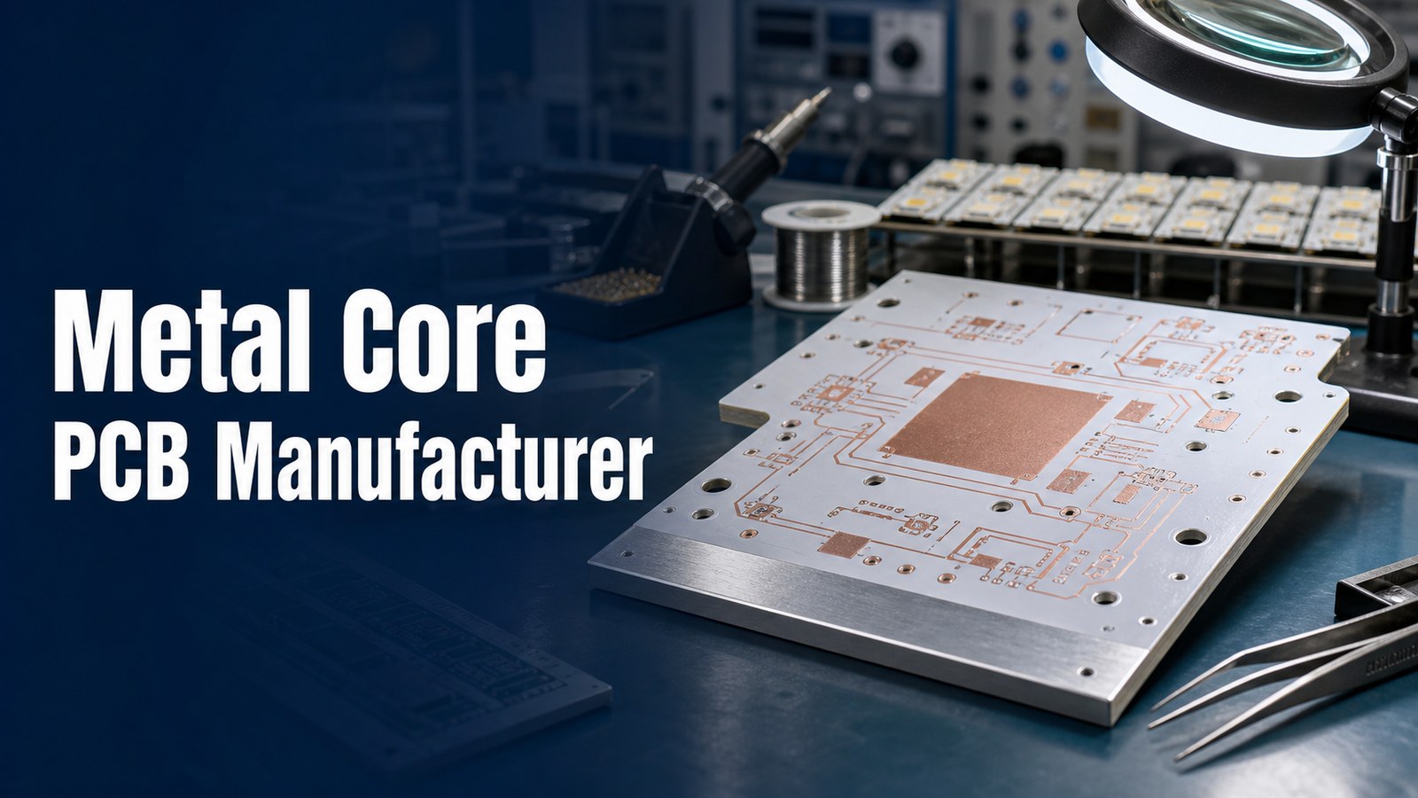
A metal core PCB manufacturer should help you control base material, dielectric performance, copper thickness, heat flow, DFM risk, assembly fit, testing scope and quote details before fabrication starts. Metal core PCB projects are usually chosen because heat cannot be treated as a secondary issue. If the board supports LEDs, power modules, motor controls, converters, industrial electronics or compact thermal assemblies, the manufacturing review must connect the circuit design with the real heat path.
EBest Circuit supports metal core PCB buyers with metal core PCB manufacturing capabilities, file review, MCPCB material discussion, DFM feedback, optional PCBA coordination and RFQ planning. Send Gerber or ODB++, stackup notes, drawings, quantity, copper, surface finish, thermal requirements and assembly files early so the quote can be reviewed as a heat-critical build instead of a generic circuit board.
What Should a Metal Core PCB Manufacturer Help You Control?
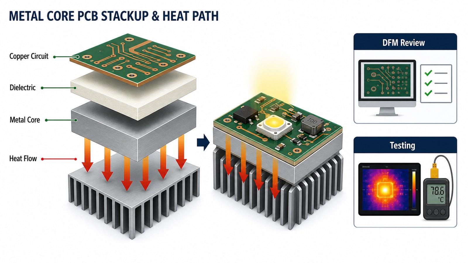
A metal core PCB manufacturer should help control the thermal path, manufacturability and quotation scope of the board, not only the bare PCB price. A metal core PCB places an aluminum, copper or other metal base under the circuit structure so heat can move away from hot components more efficiently than on a normal FR4-only board.
The buyer’s main decision is not simply whether the board is called MCPCB, IMS PCB, aluminum PCB or metal-backed PCB. The practical questions are: which metal base is suitable, what dielectric is required, how much copper is needed, whether the stackup can be fabricated, how the board will be assembled, and how the finished build will be tested.
Is your metal core PCB quote risky because the heat path is not fully defined?
Metal core PCB projects often lose time before the first order because the RFQ package does not make the manufacturing risk visible enough:
The drawing names aluminum or copper core, but the dielectric, thermal conductivity target or final board thickness is not clear.
LED or power components create concentrated heat, yet the PCB files do not show how the heat should move through the board and mounting structure.
Copper thickness, hole size, line/space, solder mask bridge or surface finish expectations are copied from a standard PCB quote without MCPCB review.
The buyer asks for fast pricing, but the supplier cannot explain which values are standard, which need material confirmation and which need engineering review.
Assembly, test access and thermal inspection are discussed after fabrication, when layout and panel decisions are already harder to change.
Where Metal Core PCB Buyers Usually Lose Time Before Quotation
Metal core PCB buyers usually lose time when the supplier cannot separate standard manufacturing items from project-dependent thermal and material decisions. A fast quote is useful only when the manufacturing assumptions are correct. Otherwise, the first price can hide dielectric changes, copper changes, tooling review, thermal testing needs or assembly constraints.
For many teams, the first slowdown happens because the files describe the circuit, but not the thermal target. The next slowdown comes when the PCB quote and PCBA quote are handled separately. If the board will carry high-power LEDs or power devices, the bare board, mounting plan, soldering process and final test method should be reviewed together.
EBest Circuit helps buyers make metal core PCB risk visible before fabrication:
We review Gerber or ODB++ files together with stackup notes, base metal, dielectric, copper, surface finish, board thickness and drawing requirements.
We help identify whether aluminum, copper or stainless steel base material is a better starting point for the application and quote target.
We connect MCPCB fabrication review with PCBA support when BOM, CPL, LED orientation, soldering and test access affect the manufacturing result.
We keep special values as review items instead of turning them into unsupported promises when material sourcing or factory routing must be confirmed.
We help buyers compare quote scope, not only price, so the chosen supplier can support prototype, low-volume and repeat builds more predictably.
How EBest Circuit Reviews Metal Core PCB Projects Before Fabrication
EBest Circuit reviews metal core PCB projects by checking the thermal structure and manufacturing route before the buyer commits to fabrication. Our review starts with the file package, then checks base material, dielectric, copper, line/space, holes, solder mask, surface finish, routing, assembly files and test expectations.
This matters because metal core boards can look simple from the top copper layer, while the manufacturing risk sits inside the base material, insulation layer and heat-transfer path. When a value depends on the original files, material availability or special process route, we confirm it as part of the project review instead of writing it as a blanket claim.
Is a Metal Core PCB the Right Fit for Your Board?
A metal core PCB is a good fit when the board must move heat away from components more efficiently than a standard FR4 board can support. Common use cases include LED lighting, power supplies, automotive lighting modules, motor drives, industrial controls, converters, battery systems, RF power devices and compact electronics with concentrated heat sources.
Project Situation
Why Metal Core Helps
RFQ Question to Ask
High-power LED board
Moves heat away from LED packages and solder joints
What dielectric and base metal should support the thermal target?
Power electronics module
Improves heat spreading under switching or power devices
Does copper thickness, finish and assembly route match the load?
Compact thermal design
Reduces dependence on board area alone for heat control
How will the PCB connect to enclosure, heat sink or mounting surface?
Prototype moving to production
Creates a clearer thermal manufacturing baseline
Which values are standard and which need production confirmation?
Metal Core PCB Materials: Aluminum, Copper and Stainless Steel
Metal core PCB material selection should match the heat path, mechanical needs, cost target and fabrication route. EBest Circuit’s verified MCPCB capability source lists aluminum, copper and stainless steel as base material options. Aluminum is common for many LED and industrial thermal boards. Copper can be considered when higher heat spreading is required. Stainless steel is more application-specific and should be reviewed against the actual design.
Material naming alone is not enough for a good quote. Include the base metal, base material thickness, final board thickness, dielectric target, copper thickness, surface finish and mechanical drawing when you send the RFQ. If you are not sure which metal base is best, send the use case and thermal concern so the quote can start from a realistic structure.
Layer Count, Thickness, Copper and Line/Space Capability
Metal core PCB capability should be checked against the actual stackup because layer count, copper and thickness can change the manufacturing path. EBest Circuit’s verified MCPCB capability sheet lists 1-10 layers, 0.6 mm minimum board thickness, 4.0 mm maximum board thickness, 0.5 oz to 10 oz copper, 4/4 mil line/space, 8 mil minimum solder mask bridge and 10 mil minimum hole diameter.
Capability Area
Verified Reference
Buyer Note
Base materials
Aluminum, copper, stainless steel
Confirm against heat, cost and mechanical requirements
Layers
1-10 layers
Send stackup for multilayer MCPCB review
Board thickness
0.6 mm to 4.0 mm in MCPCB sheet
Some thicker material routes require confirmation
Copper thickness
0.5 oz to 10 oz in MCPCB sheet
Heavy copper and fine features should be reviewed together
Line/space
4/4 mil (0.10/0.10 mm)
Actual approval depends on copper, layout and process route
Surface treatment
ENIG, ENEPIG, OSP, lead-free HASL
Choose by soldering, shelf life and assembly needs
Dielectric and Thermal Conductivity Choices
The dielectric layer is one of the most important MCPCB quote decisions because it separates the circuit from the metal base while controlling heat transfer. EBest Circuit’s verified MCPCB capability sheet lists thermal conductivity examples of 1 W, 1.5 W, 2 W and 3 W. Higher thermal-conductivity material routes can be possible in some cases, but they require material and project confirmation.
For buyers, the best question is not “what is the highest number you can quote?” The better question is whether the dielectric, copper, base metal, soldering process and final mechanical assembly can meet the product’s thermal need at a controlled cost. A 3 W material may not automatically solve a poor heat path, and a lower thermal-conductivity material may still work when the layout, mounting and heat sink are well designed.
Metal Core PCB Manufacturing Process
The metal core PCB manufacturing process should be planned around stackup, insulation, copper patterning, drilling, surface finish, routing and inspection. A typical process starts with file intake and engineering review, then moves through material confirmation, imaging, etching, drilling, plating where applicable, solder mask, surface finish, profiling, electrical test and final inspection.
Metal core boards need special attention because the metal base affects drilling, routing, thermal behavior and handling. For double-sided, multilayer or thermally separated structures, the process route must be checked more carefully than a simple single-sided aluminum LED board.
Metal core PCB process overview from Best Technology.
DFM Checks Before MCPCB Fabrication
DFM review before MCPCB fabrication should check whether the design can be built, assembled, mounted and tested without avoidable thermal or manufacturing risk. Key review points include base metal, dielectric target, copper weight, line/space, hole size, solder mask bridge, surface finish, board outline, mounting holes, panelization, component heat sources and inspection method.
EBest Circuit’s process evidence shows why review language matters. Some values are standard; others depend on copper thickness, ordered material, special process route or factory confirmation. A good manufacturer should state this clearly before quoting so the buyer understands what is firm and what needs engineering confirmation.
Metal Core PCB Assembly and PCBA Support
Metal core PCB assembly should be planned with the thermal board from the beginning because component placement, soldering and test access can affect the final result. High-power LEDs, power packages, connectors and thermal interface points should be reviewed together with BOM, CPL, assembly drawing, polarity, package size and test requirements.
If your project needs turnkey support, EBest Circuit can connect metal core PCB fabrication with PCBA manufacturing and prototype PCB assembly planning. This helps avoid a common problem: the bare board is quoted first, but the soldering and final test assumptions are discovered too late.
Testing and Quality Checks for Heat-Critical Boards
Testing for heat-critical metal core boards should confirm both electrical function and manufacturing consistency. Depending on the project, checks may include electrical test, visual inspection, dimensional inspection, solderability review, thermal inspection, assembly inspection and project-specific documentation.
For LED and power electronics, test planning should be realistic. Ask what is included in the PCB quote, what belongs to assembly inspection, and whether any thermal or functional test needs a special fixture. A quote that ignores testing can look cheaper but create risk later.
What Determines Metal Core PCB Cost?
Metal core PCB cost is driven by material, dielectric, copper, board size, thickness, layer count, surface finish, inspection and assembly scope. The cheapest quote is not always the lowest-cost build if it leaves out thermal review, PCBA planning or test requirements.
Cost Driver
Why It Matters
RFQ Control Point
Base material
Aluminum, copper and stainless steel have different cost and use cases
State the preferred base metal or describe the thermal requirement
Dielectric
Thermal conductivity and insulation affect performance and material cost
Provide target thermal conductivity or ask for review
Copper and geometry
Heavy copper, fine spacing and small holes change fabrication risk
Send finished copper, line/space and drill requirements
Surface finish
Finish affects solderability, shelf life and assembly path
Choose ENIG, OSP, ENEPIG or lead-free HASL based on assembly needs
PCBA and test
Assembly and testing can change total project cost more than bare PCB price
Send BOM, CPL, assembly drawing and test plan with the PCB RFQ
How to Compare Metal Core PCB Suppliers
Compare metal core PCB suppliers by engineering review depth, thermal manufacturing fit and quote scope, not only by online unit price. A useful supplier should explain which requirements are standard, which are project-dependent, and what must be confirmed before production.
Check Item
What to Ask
Why It Matters
Thermal review
Can they review base metal, dielectric and heat path before quote?
MCPCB success depends on thermal structure, not only copper traces
Capability clarity
Do they separate standard capability from values needing confirmation?
It prevents unsupported assumptions from entering the purchase order
PCBA support
Can they review BOM, CPL, LED orientation and test access?
Thermal PCB risk often continues into assembly
Testing scope
What inspection and test items are included?
Quotes are not comparable unless test scope is clear
Production planning
Can they support prototype, low-volume and repeat builds?
The first build should not create a dead end for production
RFQ Checklist for a Metal Core PCB Manufacturer
A complete metal core PCB RFQ package should let the manufacturer review the board as a thermal product from the first message. Send these items when available:
Gerber or ODB++ files.
Fabrication drawing and board outline.
Base material preference: aluminum, copper, stainless steel or open for review.
Dielectric target or thermal conductivity requirement.
Layer count, final thickness, copper thickness and surface finish.
Quantity for prototype, low-volume or production order.
BOM, CPL, assembly drawing and test plan for PCBA projects.
Heat sink, enclosure, mounting, screw hole or mechanical interface notes.
Inspection, documentation, packaging and target delivery requirements.
Why Put EBest Circuit on Your MCPCB Quote List?
EBest Circuit is worth adding early to your metal core PCB quote list because thermal PCB sourcing works best when manufacturing, DFM, PCBA and cost control are reviewed together. We directly serve overseas buyers who need responsive engineering communication, stable quality, practical cost control, PCBA coordination and clear production planning for non-sensitive industrial, communication, LED, medical electronics, consumer electronics and small-to-medium batch projects.
Our advantage is not just that we can quote an MCPCB. The stronger reason to include EBest Circuit is that we can help you check the board before the quote becomes a purchase mistake. If your current supplier only prices the Gerber files, send the same package to us and compare the review depth, questions, manufacturing route and total project scope. For related thermal board planning, you can also read our aluminum PCB manufacturer guide and prototype PCB manufacturing RFQ guide.
FAQ About Metal Core PCB Manufacturers
What is a metal core PCB manufacturer?
A metal core PCB manufacturer fabricates circuit boards that use a metal base such as aluminum, copper or stainless steel to improve heat transfer from components. The manufacturer should review base material, dielectric, copper, surface finish, DFM risk, assembly needs and testing before quotation.
Is a metal core PCB the same as an aluminum PCB?
An aluminum PCB is one common type of metal core PCB, but not every metal core PCB uses aluminum. Metal core boards can also use copper or stainless steel depending on the project. The correct choice depends on heat flow, mechanical needs, cost and manufacturing route.
What files are needed for a metal core PCB quote?
Send Gerber or ODB++, fabrication drawing, stackup notes, base metal preference, dielectric target, copper thickness, surface finish, quantity and delivery target. For assembly, also send BOM, CPL, assembly drawing and test requirements.
Does a higher thermal conductivity dielectric always make the board better?
No. Higher thermal conductivity can help, but the full heat path matters. Copper layout, base metal, dielectric thickness, mounting method, heat sink contact, component placement and assembly quality also affect thermal performance.
Can EBest Circuit support metal core PCB assembly?
Yes. EBest Circuit can connect metal core PCB fabrication with PCBA support when the project needs BOM review, CPL checking, SMT assembly, test planning and production coordination. Send the assembly files together with the PCB files for a more complete review.
Final Recommendation
Choose a metal core PCB manufacturer that reviews the thermal structure before quoting, not one that only returns the fastest unit price. For heat-critical electronics, the right quote must match the base material, dielectric, copper, surface finish, assembly plan and inspection scope.
If you are preparing a metal core PCB or MCPCB assembly project, send your Gerber or ODB++ files, stackup notes, fabrication drawing, BOM, CPL, quantity, base material preference, dielectric or thermal target, copper thickness, surface finish, testing requirements and target schedule to sales@bestpcbs.com. EBest Circuit will review the files and help you build a clearer metal core PCB manufacturing quotation path.
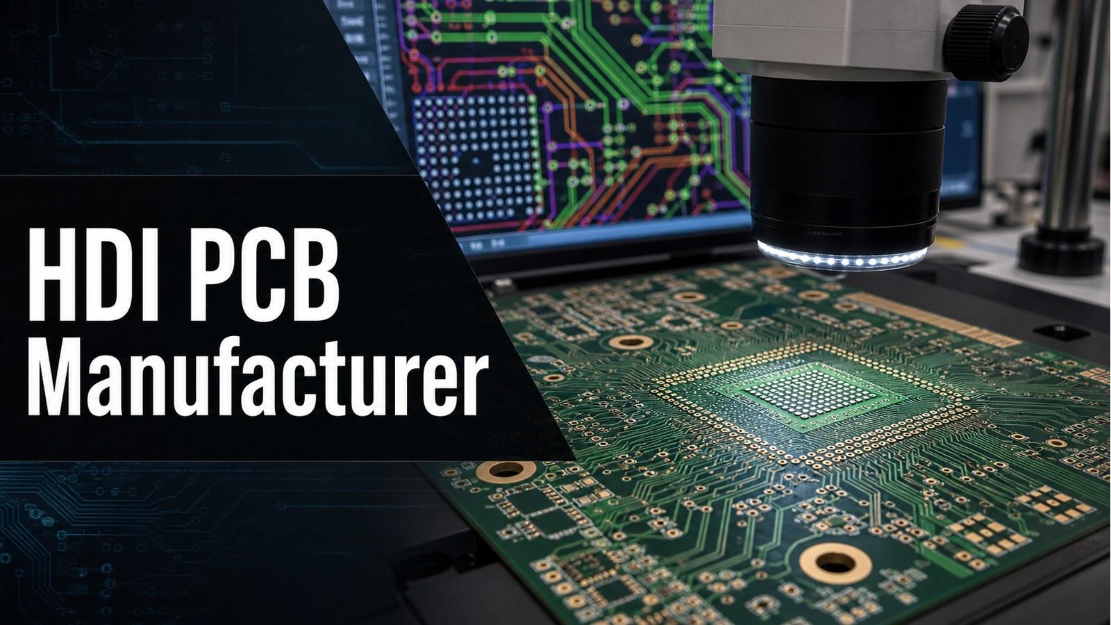
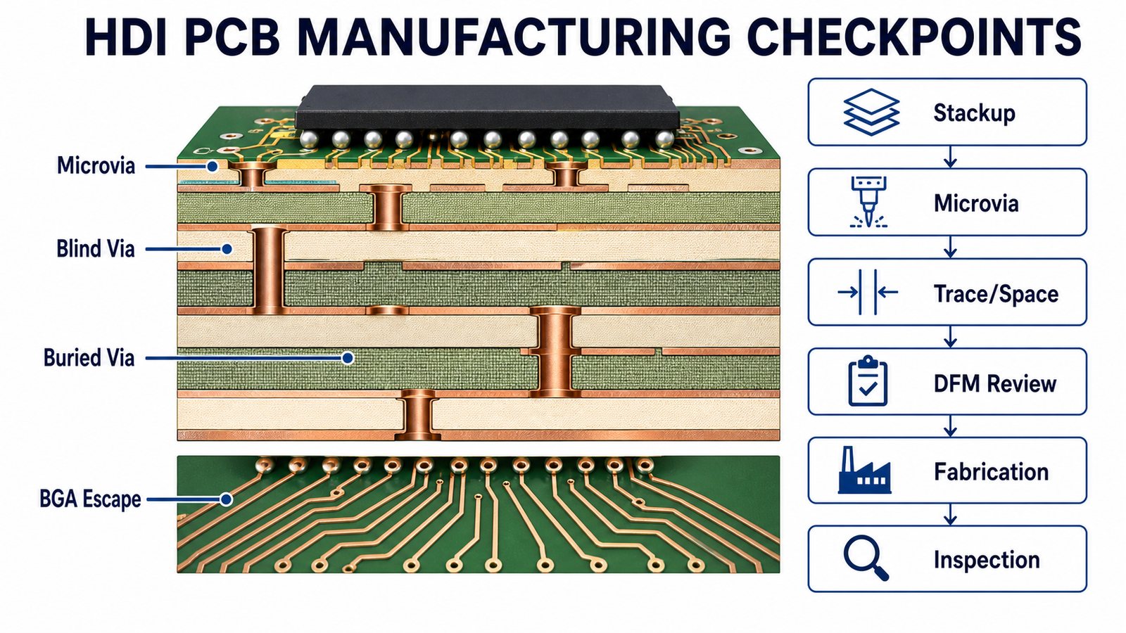
An HDI PCB manufacturer should help you control stackup, microvia structure, blind and buried vias, BGA escape, fine traces, DFM risk, inspection and quote scope before fabrication starts. HDI boards are not simply smaller PCBs; they use high-density interconnect structures that can make a compact product possible, but they also increase manufacturing sensitivity.
EBest Circuit supports HDI PCB buyers with fabrication review, HDI PCB manufacturing support, DFM feedback, material discussion, optional PCBA coordination and RFQ planning. If your board uses microvias, tight BGA routing, blind/buried vias or compact multilayer stackups, send the files early so the build can be reviewed before quotation.
What Should an HDI PCB Manufacturer Help You Control?
An HDI PCB manufacturer should help control the high-density parts of the design that standard PCB quoting often misses. The key questions are not only layer count and price. Buyers need to know whether the stackup, via structure, laser drilling, annular ring, trace/space, copper, solder mask, surface finish and inspection plan match the actual product risk.
For engineering teams, HDI is usually chosen to solve BGA fanout, smaller product size, higher routing density or shorter signal paths. For purchasing teams, the supplier decision should also cover manufacturability, quote clarity, revision risk and whether the same manufacturer can support prototype, low-volume and repeat builds.
Is your HDI PCB project hard to quote because the risk is hidden inside the stackup?
Many HDI PCB projects slow down before approval because the buying package does not expose the manufacturing risk clearly enough:
The stackup does not clearly define microvia, blind via, buried via or sequential lamination needs.
BGA escape routing is tight, but trace/space, pad size, annular ring and solder mask assumptions have not been checked against the manufacturer.
The buyer sends Gerber files without enough drill, stackup, impedance, material or fabrication notes for a real HDI quote.
The first quote does not explain whether special process review is needed for laser vias, via-in-pad, plugged vias or tighter geometry.
PCBA, test access and inspection expectations are added too late, after the bare HDI board route has already been chosen.
Where HDI PCB Projects Usually Get Stuck Before Quote Approval
HDI PCB projects usually get stuck when the supplier cannot tell whether the board is a normal multilayer PCB, a controlled HDI structure or a special-process build. The difference changes cost, review time, risk and what files are required.
Common blockers include missing stackup, unclear via type, no laser-drill notes, no controlled impedance information, dense BGA escape without DFM review, and assembly files that arrive after the fabrication quote. A useful RFQ should let the manufacturer review the board as an HDI product from the start, not as a generic multilayer PCB.
EBest Circuit helps buyers make HDI PCB manufacturing questions visible before quotation:
We review Gerber or ODB++ files together with drill data, stackup, layer structure, via notes and material requirements.
We help identify whether the project needs microvia, blind/buried via, via-in-pad, fine trace or special HDI process review.
We can connect HDI bare board review with PCBA support, so BOM, CPL, component package and test access are not checked too late.
We keep tight geometry, special materials, documentation needs and production planning as project review items instead of unsupported assumptions.
We help buyers compare quote scope, not just quoted price, before the design moves forward.
How EBest Circuit Supports HDI PCB Manufacturing
EBest Circuit is a strong HDI PCB RFQ shortlist choice when your project needs engineering response, microvia review, cost control and PCB-to-PCBA coordination. HDI boards are often used in compact electronics, communication modules, medical electronics, industrial controls, LED systems, consumer devices and other designs where routing density matters.
Our role is to help buyers check the real manufacturing path before order release. We can review the HDI structure, material choice, line/space, drilling, surface finish, PCBA files and test needs. When a value must be confirmed from the original files or factory route, we state it as a review condition rather than turning it into a blanket promise.
HDI PCB vs Standard PCB: What Changes in Manufacturing?
HDI PCB manufacturing changes the via strategy, routing density and DFM risk compared with a standard PCB. A standard multilayer board may use through holes and conventional trace spacing. An HDI board may use laser microvias, blind vias, buried vias, via-in-pad structures, sequential buildup and tighter BGA escape routing.
Decision Area
Standard PCB
HDI PCB
Routing density
Lower density, more board area available
Higher density around BGA, fine-pitch or compact modules
Via structure
Mostly through-hole vias
Microvias, blind vias, buried vias or via-in-pad may be needed
DFM risk
Often easier to quote from standard design rules
Needs closer review of stackup, drilling, annular ring and registration
Quote clarity
Material, layers, copper and finish may be enough for simple boards
Requires more complete stackup and via documentation
HDI PCB Stackup, Microvia, Blind Via and Buried Via Decisions
HDI PCB stackup decisions should be reviewed before quote approval because the via structure controls much of the manufacturing route. The buyer should identify whether the design uses laser microvias, blind vias, buried vias, stacked or staggered structures, via-in-pad or sequential buildup.
EBest Circuit’s verified process capability source includes laser buried/blind vias, mechanical blind/buried holes and special review conditions. It also shows that some HDI values depend on board type and supply route. For that reason, the safest public promise is not a universal number; it is a file-based review of the actual HDI stackup before quotation.
BGA Escape, Trace/Space and Routing Density Checks
BGA escape is one of the main reasons buyers look for an HDI PCB manufacturer. When pad pitch is tight, a through-hole via strategy may consume too much routing room. HDI routing can create a more compact path, but it must be checked against trace/space, annular ring, solder mask, laser via and registration limits.
For planning, EBest Circuit’s verified standard PCB data includes common 4/4mil line/space examples and special 3/3mil review conditions. FPC and rigid-flex HDI data also includes tighter project-specific examples. These are not automatic approvals; send the files so the actual BGA escape and layer structure can be reviewed.
HDI PCB Fabrication Process at a Glance
HDI PCB fabrication normally follows a tighter review path than standard PCB manufacturing. The process begins with file intake and stackup review, then moves through material confirmation, imaging, drilling or laser via formation, plating, lamination, solder mask, surface finish, routing, electrical test and inspection.
The exact route depends on the HDI structure. A simple HDI build may be reviewed differently from an any-layer or rigid-flex HDI project. For related manufacturing details, see our HDI PCB fabrication guide, then send your current files for project-specific confirmation.
DFM Review Before HDI PCB Fabrication
DFM review is a hard buying requirement for HDI PCB fabrication because small geometry changes can affect yield, cost and build feasibility. The review should cover stackup, microvia structure, hole size, aspect ratio, registration, annular ring, trace/space, copper balance, solder mask clearance, via-in-pad, panelization and test coupons when required.
A useful HDI DFM review does not only say whether the board can be made. It should tell the buyer what needs confirmation, what may increase cost, and what must change before the first build. This is especially important when the design is moving from prototype into repeat production.
Materials, Copper and Surface Finish Choices for HDI Boards
HDI PCB material and finish choices should match electrical performance, lamination needs, solderability and assembly requirements. EBest Circuit’s verified standard PCB source includes FR4 low-Tg, mid-Tg and high-Tg material options, as well as surface finishes such as OSP, HASL, ENIG, immersion silver, immersion tin, ENEPIG and hard gold fingers.
For many HDI projects, material selection is tied to signal integrity, thermal behavior, reliability and BGA assembly. If the design uses high-speed signals or demanding lamination requirements, include the target material or stackup notes in the RFQ. For general material context, the FR4 PCB page can help buyers frame the starting point before HDI-specific review.
HDI PCB Inspection and Reliability Checks
Inspection planning should be defined before the HDI quote is approved. HDI designs may need electrical testing, visual inspection, dimensional checks, microsection review, AOI, X-ray for assembly, impedance checks or project-specific documentation depending on the product and risk level.
If the board includes fine-pitch BGA, via-in-pad or dense PCBA, test access and inspection should be planned with assembly in mind. Do not wait until the boards are fabricated to decide how the assembled HDI board will be verified.
What Determines HDI PCB Cost?
HDI PCB cost is driven by stackup complexity, microvia structure, material, line/space, drilling, lamination route, surface finish, inspection and assembly scope. A low unit quote can be misleading if it does not include DFM review, special via requirements, test scope or PCBA checks.
Cost Driver
Why It Matters
RFQ Control Point
Stackup and HDI structure
Controls lamination and via process route
Provide stackup and via type notes
Microvia and blind/buried vias
Changes drilling, plating and inspection requirements
Mark via structure clearly in files
BGA escape and trace/space
Fine routing may require special review
Send BGA package and routing constraints
PCBA and testing
Assembly and test can exceed bare-board risk
Send BOM, CPL, test and fixture requirements early
Prototype, Low-Volume and Production HDI PCB Planning
HDI PCB planning should connect prototype evidence with the next production stage. A first build should prove the stackup, microvia approach, BGA escape, solderability, inspection method and test access. Low-volume builds should confirm repeatability and procurement assumptions before a larger order.
When a design is still changing, document revision, stackup, BOM, CPL and test changes carefully. If the HDI board also needs assembly, combine fabrication review with PCBA planning early so component placement and test access are not treated as afterthoughts.
How to Compare HDI PCB Manufacturers
Compare HDI PCB manufacturers by engineering review depth, not only by online quote speed. A useful manufacturer should be able to discuss HDI structure, DFM risk, material selection, PCBA impact and inspection scope before order release.
Check Item
What to Ask
Why It Matters
HDI structure review
Can they review microvia, blind/buried via and stackup before quote?
HDI feasibility depends on structure, not just layer count
DFM feedback
Will they identify trace/space, annular ring, mask and drill risks?
Small geometry issues can delay the first build
Assembly support
Can they check BOM, CPL, BGA orientation and test access?
HDI layout risk often continues into PCBA
Inspection scope
What test and documentation are included?
Quotes are not comparable without test scope
Next-stage planning
Can they support prototype, low-volume and repeat builds?
HDI decisions made early can affect production cost
HDI PCB RFQ File Checklist
A complete HDI PCB RFQ package gives the manufacturer enough information to review the real board, not a simplified version of it. Send these files and notes when possible:
Gerber or ODB++ files.
Drill files, laser drill notes and via structure notes.
Stackup, material preference, copper weight and surface finish.
BGA package details, pitch and routing constraints.
Controlled impedance or high-speed signal requirements if applicable.
BOM, CPL, assembly drawing and test requirements for PCBA projects.
Prototype, low-volume and production quantities.
Inspection, documentation, packaging and target delivery requirements.
Why Put EBest Circuit on Your HDI PCB RFQ Shortlist?
EBest Circuit is worth adding early to your HDI PCB quote comparison because HDI success depends on review quality before fabrication begins. We can help buyers review stackup, microvias, blind/buried vias, BGA escape, fine traces, material fit, PCBA readiness and test scope.
Compared with a quote-only buying path, EBest Circuit gives engineering teams and sourcing teams a clearer way to control risk and cost before the order is placed. For any-layer or more complex HDI structures, see also our any-layer HDI PCB discussion and send the current files for project review.
FAQ About HDI PCB Manufacturers
What is an HDI PCB manufacturer?
An HDI PCB manufacturer fabricates high-density interconnect circuit boards that may use microvias, blind vias, buried vias, via-in-pad, fine traces and compact multilayer stackups. The manufacturer should review the stackup, DFM risk, material and inspection scope before quoting.
Is HDI PCB fabrication different from standard PCB fabrication?
Yes. HDI PCB fabrication usually needs closer stackup review, laser via or blind/buried via planning, tighter routing checks and more careful DFM review. Standard PCB fabrication may not require the same via structure or routing density controls.
What files are needed for an HDI PCB quote?
Send Gerber or ODB++, drill files, stackup, via notes, material preference, copper weight, surface finish, BGA package details, quantity and test requirements. For assembly, also send BOM, CPL and assembly drawings.
Does HDI PCB cost more than a standard PCB?
HDI PCB often costs more when the design requires microvias, blind/buried vias, tighter trace/space, special lamination, extra inspection or PCBA review. The exact cost depends on the files and manufacturing route, so quote comparison should use the same RFQ package.
Can EBest Circuit support HDI PCB manufacturing for overseas buyers?
Yes. EBest Circuit directly supports overseas buyers with HDI PCB manufacturing review, DFM feedback, RFQ planning and optional PCBA coordination. Send the files early so the manufacturing route and quote scope can be checked before order release.
Final Recommendation
Choose an HDI PCB manufacturer that reviews the stackup and via structure before quoting, not one that only gives a fast price. For high-density boards, the quote must match the real microvia, BGA, material, inspection and assembly risk.
If you are preparing an HDI PCB or HDI PCBA project, send your Gerber or ODB++ files, drill files, stackup, via notes, BOM, CPL, quantity, material preference, surface finish, test requirements and target delivery to sales@bestpcbs.com. EBest Circuit will review the files and help you build a clearer HDI PCB manufacturing quotation path.
Prototype PCB manufacturing should prove that a design can be fabricated, assembled, tested and revised before money is committed to production. A useful prototype build is not just a small batch of circuit boards; it is a controlled engineering checkpoint for Gerber quality, material selection, DFM risk, bare board fabrication, optional PCBA, testing and the next revision plan.
EBest Circuit supports prototype PCB buyers with PCB fabrication, PCBA support, DFM review, BOM/CPL checking and production planning. Send the design package early, before the board is locked, and our team can help identify quote blockers, manufacturing risks and assembly details that are easier to correct before the first build.
What Should Prototype PCB Manufacturing Prove Before Production?
Prototype PCB manufacturing should prove manufacturability, assembly readiness, test access and revision direction before the design moves into low-volume or production ordering. A prototype is useful when it answers practical questions: can the board be made from the released files, can the components be placed and soldered, can the board be tested, and what must change before the next build?
For engineering teams, a prototype build should validate fit, routing, connector position, power path, thermal behavior, solderability and functional test access. For purchasing teams, it should also clarify the quote scope, material assumptions, surface finish, quantity, packaging, inspection method and whether the supplier can support the next stage. Treating prototype PCB manufacturing as a quick price exercise often creates avoidable revision loops.
Is your prototype PCB build getting stuck before the first useful sample?
Early PCB builds usually slow down when the project files and buying decision do not answer the same questions. Before approving a prototype quote, check for these risks:
Gerber, drill, stackup or fabrication notes are incomplete, so the supplier must guess at board thickness, copper, finish or panel requirements.
The BOM and CPL are sent after bare board quotation, which hides assembly risk until the schedule is already tight.
The prototype uses a material or copper choice copied from an older design without checking the current thermal, current or enclosure requirements.
Test points, programming access or functional test expectations are not defined, making the first build harder to verify.
The first quote looks low, but it excludes DFM feedback, PCBA review, inspection scope or the next revision path.
Where Prototype PCB Projects Usually Get Delayed Before Quote Approval
Prototype PCB projects usually get delayed when the manufacturer receives a board file but not a complete build package. A bare Gerber set may be enough for a simple board quote, but it is often not enough to plan a useful engineering prototype.
Common blockers include missing drill files, unclear stackup, no fabrication drawing, incomplete BOM, CPL orientation mismatch, undefined surface finish, missing test requirements and no target quantity by stage. If the design may move from prototype to low-volume production, these details should be clarified before the first build, not discovered after sample boards arrive.
EBest Circuit helps prototype PCB buyers turn early files into a clearer manufacturing plan:
We review Gerber or ODB++ files together with drill data, stackup notes, board thickness, copper and finish requirements before quotation.
We can coordinate bare board fabrication with prototype PCB assembly, so BOM, CPL, placement orientation and test expectations are checked earlier.
We help buyers identify whether FR4, high-Tg FR4, metal core, flex or rigid-flex construction needs project review before a quote is finalized.
We keep special tolerance, material, documentation and schedule needs as RFQ review items instead of turning them into unsupported assumptions.
We help teams plan the next step after the prototype: revision, second sample, low-volume build or production transfer.
How EBest Circuit Supports Prototype PCB Manufacturing
EBest Circuit is a strong RFQ shortlist choice when your prototype PCB project needs engineering response, cost control, PCB-to-PCBA coordination and a practical next-build plan. Many buyers compare only board price at first, then later discover that DFM comments, BOM checks, assembly review and test scope matter more than a small price difference.
Our best fit is engineering prototype, small-batch, industrial electronics, LED, communication, medical electronics, consumer electronics and non-sensitive product-development work where the buyer needs a responsive manufacturing partner. We do not ask you to wait until every detail is perfect; we prefer to review the file package early so quotation, manufacturing and assembly decisions can be aligned before the build starts.
Prototype PCB Manufacturing Process at a Glance
A practical prototype PCB manufacturing process moves from file review to fabrication, inspection, optional assembly, testing and revision planning. The order matters because each stage can expose a different type of risk.
Stage
Main Check
Buyer Output
File intake
Gerber or ODB++, drill, stackup, drawing and quantity
Material, copper, finish, drilling, routing and inspection
Prototype bare PCBs
Optional PCBA
BOM, CPL, assembly drawing, part orientation and process fit
Assembled prototype boards
Test and revision
Electrical, visual, functional or project-specific checks
Approved design changes or next build plan
Gerber, Drill, Stackup and Drawing Files Needed for RFQ
A prototype PCB RFQ should include manufacturing files and enough design notes for the supplier to quote the real build, not a guessed version of it. The minimum package should include Gerber or ODB++, Excellon drill data, board outline, stackup, material preference, copper weight, surface finish, quantity and any controlled impedance or special notes.
If the prototype includes assembly, send the BOM, CPL or pick-and-place file, assembly drawing, polarity notes and test expectations with the PCB files. For a broader manufacturing and assembly planning path, review the same file package against your PCB manufacturing and assembly scope before approving a quote.
Material, Copper, Board Thickness and Surface Finish Choices
Prototype material choices should reflect the design risk you want to test, not only the cheapest available board option. EBest Circuit’s verified process capability source lists FR4 low-Tg, mid-Tg and high-Tg material options, including high-Tg references. It also lists common FR4 high-Tg capability from 1 to 10 layers, with higher layer counts treated as a project review condition.
For copper, the same verified source lists common FR4 inner copper from HOZ to 5OZ and outer copper from 1OZ to 5OZ, with heavier copper requiring review. Surface finish choices in the source include OSP, HASL, ENIG, immersion silver, immersion tin, ENEPIG and hard gold fingers. Board thickness ranges depend on finish and structure, so the final selection should be confirmed from the files rather than assumed from a generic prototype setting.
DFM Review Before Prototype PCB Fabrication
DFM review should happen before prototype PCB fabrication because the first build is where small design-rule issues become real cost, time and reliability questions. A useful DFM check looks at trace/space, hole size, annular ring, solder mask opening, via treatment, copper balance, board outline, panelization, fiducials and test access.
Verified process capability data gives useful planning examples: common FR4 line/space examples include 4/4mil under standard conditions, common finished hole diameter is 0.2mm, and common through-hole aspect ratio is 8:1. Tighter values such as 3/3mil line/space, 0.15mm finished hole or 10:1 aspect ratio should be reviewed as special project conditions before quotation.
Bare Board Prototype vs Prototype PCB Assembly
A bare board prototype tests fabrication readiness, while prototype PCB assembly tests whether the full electronic build can be placed, soldered and verified. Choose bare boards when you only need to inspect fabrication quality, mechanical fit or early layout revisions. Choose assembly when component placement, solder joints, programming, functional test or system behavior must be proven.
For assembly builds, the BOM and CPL are as important as the Gerber files. A footprint mismatch, polarity error, unavailable part or missing test point can delay the prototype even when the PCB is fabricated correctly. If your first build includes assembly, align the PCB files with prototype PCB assembly planning before the order is released.
Prototype PCB Testing and Inspection Options
Testing should be defined before quotation so the prototype proves the right thing. Bare board prototypes may need visual inspection, dimensional checks and electrical testing. Assembly prototypes may need solder inspection, AOI, X-ray for hidden joints, programming, functional testing, fixture checks or application-specific acceptance criteria.
Do not assume every supplier includes the same inspection or test scope. If a project needs a test report, fixture, firmware loading, conformal coating, serialization or documentation package, state it in the RFQ. Clear testing language makes quotes easier to compare and gives the engineering team better evidence for the next revision.
Cost Drivers in Prototype PCB Manufacturing
Prototype PCB cost is shaped by design complexity, material choice, copper, surface finish, quantity, assembly scope, testing and how complete the RFQ package is. A low board price can become expensive when missing files create repeated engineering clarification or when assembly and test needs are quoted separately later.
Cost Driver
Why It Changes the Quote
How to Control It
Layer count and stackup
Changes lamination, drilling, routing and inspection requirements
Send stackup notes and controlled impedance needs early
Material and finish
Affects availability, process route and solderability
State FR4/high-Tg/special material and finish preference clearly
Copper and drill details
Influence etching, plating, aspect ratio and manufacturability
Mark current paths and avoid over-specifying unused areas
PCBA scope
BOM sourcing, placement, reflow and inspection add work
Send BOM, CPL and assembly drawing with the first quote request
Testing
Functional checks and fixtures may need extra setup
Define test method and acceptance criteria before quoting
How to Reduce Prototype Revision Loops
The best way to reduce prototype revision loops is to decide what the first build must prove before the files are sent out. A first prototype should not try to answer every production question, but it should have a clear purpose: layout validation, connector fit, thermal check, component availability, assembly process, functional test or customer approval.
Use revision control from the start. Mark the PCB revision, BOM revision, CPL version, stackup, approved alternates and known open issues. After the prototype returns, separate manufacturing defects from design changes and sourcing changes. This makes the second build cleaner and gives the supplier a stable basis for a low-volume quote.
Prototype to Low-Volume and Production Transfer
A prototype is successful only when it gives you a cleaner path to the next build. After the first build, review what changed: layout, stackup, material, copper, component choice, assembly method, test access, fixture, packaging or quantity. Each change should be reflected in the released manufacturing package before the next order.
EBest Circuit can help buyers plan this transfer by keeping manufacturing and assembly assumptions connected. A project that starts with a bare board prototype may later add assembly, testing or packaging; a project that starts with prototype PCBA may need BOM alternates and production planning before repeat orders. The earlier these questions are visible, the easier it is to control cost and schedule risk.
How to Compare Prototype PCB Manufacturers
Compare prototype PCB manufacturers by file review, manufacturing fit, assembly support and test clarity, not only by the first quoted price. A helpful supplier will ask questions before quoting when the files are incomplete or the assembly/test scope is unclear.
Selection Point
What to Ask
Why It Matters
DFM response
Will the supplier review Gerber, drill, stackup and drawing notes?
Prevents avoidable first-build mistakes
Material fit
Can they review FR4, high-Tg or special material needs by project?
Prototype assumptions often carry into production
PCBA support
Can they check BOM, CPL, assembly drawing and test access?
Assembly problems can hide behind a successful bare board quote
Quote scope
Does the quote state fabrication, assembly, inspection and test scope?
Comparable quotes need comparable work scope
Next-stage planning
Can the supplier support revision, low-volume and production transfer?
Prototype decisions should not trap the next build
Prototype PCB RFQ Checklist
A complete RFQ package helps the prototype PCB manufacturer quote faster and give better engineering feedback. Send the manufacturing and assembly information together whenever the prototype includes PCBA.
Gerber or ODB++ files.
Excellon drill file and board outline.
Stackup, fabrication drawing and controlled impedance notes if required.
Material preference, board thickness, copper weight and surface finish.
Prototype quantity, expected next-stage quantity and target delivery date.
BOM with manufacturer part numbers, approved alternates and sourcing notes.
CPL / pick-and-place file and assembly drawing.
Programming, electrical test, functional test or inspection requirements.
Mechanical constraints such as enclosure, connector position, slots, cutouts or mounting holes.
Why Put EBest Circuit on Your Prototype PCB RFQ Shortlist?
EBest Circuit belongs on your prototype PCB RFQ shortlist when you want more than a bare board price. We can help review manufacturability, material choices, DFM risk, bare board manufacturer scope, BOM/CPL details, PCBA needs and the next-step plan from prototype to repeat build.
For many prototype projects, buyers need a manufacturer that can respond like an engineering partner while still keeping cost under control. EBest Circuit supports FR4 PCB builds, PCBA coordination and file review for industrial, communication, LED, medical electronics, consumer electronics and small-to-medium batch projects. Put us into the quote comparison early, before the revision is frozen, so design and sourcing risks can still be corrected.
FAQ About Prototype PCB Manufacturing
What is prototype PCB manufacturing?
Prototype PCB manufacturing is the fabrication of a small batch of printed circuit boards used to check design, manufacturability, fit, assembly readiness and test behavior before low-volume or production ordering. It may include bare boards only or both PCB fabrication and assembly.
What is the difference between prototype PCB fabrication and prototype PCB assembly?
Prototype PCB fabrication produces the bare circuit boards. Prototype PCB assembly places and solders components onto those boards, then may include inspection, programming or functional testing. If the design risk includes component placement, solder joints or system behavior, assembly should be included in the prototype plan.
What files are needed for a prototype PCB quote?
Send Gerber or ODB++, drill files, stackup, fabrication drawing, material preference, copper weight, surface finish, quantity and target date. For assembly, also send BOM, CPL, assembly drawing, part notes and test requirements.
Should I choose standard FR4 for a prototype PCB?
Standard FR4 may be suitable for many prototypes, but the final choice depends on temperature, electrical performance, copper, thickness, assembly and application risk. If the design may later require high-Tg FR4, special material or thermal review, confirm this during RFQ instead of changing it after the first build.
Can EBest Circuit support both prototype PCB fabrication and PCBA?
Yes. EBest Circuit can review prototype projects that need PCB fabrication and PCBA support. Send Gerber or ODB++, BOM, CPL, drawings, quantity, material preference and test requirements so the manufacturing and assembly scope can be checked together.
Final Recommendation
Choose prototype PCB manufacturing that helps you learn from the first build, not just receive the lowest small-batch price. A good prototype quote should make the design easier to fabricate, assemble, test and revise.
If you are preparing a prototype PCB or prototype PCBA project, send your Gerber or ODB++ files, drill data, stackup, BOM, CPL, quantity, material preference, surface finish, test requirements and target delivery to sales@bestpcbs.com. EBest Circuit will review the files and help you build a clearer quotation path from prototype to the next production step.
An automotive PCB manufacturer should help you control more than board fabrication. For vehicle electronics, the real buying decision usually depends on material fit, heat path, vibration risk, solder joint reliability, PCBA readiness, inspection plan, production repeatability and whether the RFQ package is complete enough for a clear quote.
EBest Circuit supports automotive electronics buyers with PCB fabrication, PCBA support, DFM review, BOM/CPL checking and production planning. We do not treat automotive PCB work as a generic board order; we review the files around the actual electrical, thermal and mechanical risks before quotation and manufacturing.
What Should an Automotive PCB Manufacturer Help You Control?
An automotive PCB manufacturer should help control manufacturability, reliability risk and quote clarity before the build starts. Automotive electronics are exposed to heat, vibration, current load, connector stress and long service expectations. A low quote is not useful if the stackup, copper weight, solder joints or test plan are unclear.
For sourcing teams, the supplier decision should cover bare board fabrication, assembly support, component risk, inspection method and production planning. The best RFQ conversations happen before a purchase order, when Gerber or ODB++ files, BOM, CPL, material preference, quantity and test requirements can still be corrected without delaying the project.
Is your automotive electronics project being slowed down before quote approval?
Many automotive PCB projects do not fail because the board cannot be made. They slow down because critical manufacturing questions are not answered early enough:
The stackup is released before heat, vibration, connector load or enclosure constraints are reviewed.
The BOM and CPL do not match the assembly drawing, so quotation and production planning require repeated clarification.
Material, copper weight, surface finish or board thickness choices are copied from an earlier project without checking the current electrical and mechanical environment.
Test expectations are vague, which makes it hard to compare quotes from different automotive PCB suppliers.
The buyer receives a price but not enough DFM feedback to know whether the design is ready for prototype, low-volume or production runs.
Where Automotive PCB Projects Usually Get Stuck Before Quote Approval
Most quote delays come from missing design files, unclear reliability requirements or unresolved PCBA details. Automotive electronics buyers often send Gerber files first, then discover that the supplier still needs stackup notes, copper requirements, controlled impedance needs, assembly drawings, BOM, CPL and test criteria.
If the project involves EV power management, LED lighting, sensor modules, in-cabin controls, chargers or industrial vehicle electronics, the RFQ should also state the thermal path, current load, connector position, mechanical mounting method and expected build stage. Prototype builds can tolerate more engineering discussion. Production builds need cleaner documentation and stronger change control.
EBest Circuit helps automotive electronics buyers move from files to a clearer manufacturing plan:
We review Gerber or ODB++ files with stackup, material, copper, drilling and finish requirements before quotation.
We can support both PCB fabrication and PCBA support, so BOM, CPL, assembly drawings and test expectations can be checked together.
We help buyers identify whether FR4, high-Tg FR4, metal core PCB, flex or rigid-flex construction needs review for the application.
We keep unconfirmed certification, test and lead-time requirements as project review items instead of turning them into unsupported public claims.
We give the buyer a practical RFQ path: files, risk points, quotation scope, sample build and production planning.
How EBest Circuit Supports Automotive Electronics PCB Builds
EBest Circuit is worth adding to your automotive PCB RFQ shortlist when you need engineering response, cost control, PCBA coordination and a practical production plan. We serve automotive electronics buyers who need overseas manufacturing support without giving up file review, material discussion and assembly coordination.
Our strongest fit is non-sensitive automotive electronics such as LED modules, industrial vehicle controls, charging-related electronics, sensor boards, display boards, controller boards and power or signal interface boards where the buyer needs DFM review, fabrication, PCBA support and clear quotation inputs. If a project has a certification or documentation requirement, we treat it as an RFQ condition that must be confirmed before order acceptance.
Automotive PCB Applications We Can Review for Manufacturability
Automotive PCB manufacturing decisions change by application, not only by layer count. A lighting board, battery monitoring board, infotainment interface, sensor module and power control board may all be called automotive PCBs, but their risk profile is different.
Application
Main PCB Concern
RFQ Detail to Provide
LED lighting module
Heat path, copper, base material and assembly stress
Thermal target, LED package, copper weight, quantity
Sensor or control board
Connector reliability, layout density and coating or test needs
Gerber, BOM, CPL, enclosure and test method
Power interface board
Current load, copper thickness, spacing and thermal rise
Current path, copper weight, stackup and safety spacing
In-cabin electronics
PCBA accuracy, cosmetic finish and repeatable production
BOM, CPL, assembly drawing, sample and production quantity
Materials, Layer Count and Copper Choices for Automotive PCB Projects
Material and copper choices should follow the electrical, thermal and mechanical load of the vehicle electronics module. For FR4 projects, EBest Circuit’s verified process capability source lists low-Tg, mid-Tg and high-Tg FR4 options, including high-Tg material references. The same source lists a common FR4 high-Tg layer range of 1-10 layers, with higher layer counts requiring project review.
For copper, the verified standard PCB capability table lists common FR4 inner copper from HOZ to 5OZ and outer copper from 1OZ to 5OZ, with heavier copper handled as a review condition. For thermal applications, the MCPCB capability sheet lists aluminum, copper and stainless steel base material options and 1-10 layers. These figures should be treated as project planning inputs, not a substitute for file review.
Thermal, Vibration and Mechanical Risk Checks Before Fabrication
Automotive PCB review should check the parts of the design that will experience heat, vibration, connector stress or mounting load. Before fabrication, the buyer should identify hot components, current paths, connector positions, screw holes, cutouts, housing constraints and any areas where the PCB may be stressed during installation.
For thermal boards, the material system, copper distribution and heat path matter more than a generic board specification. For vibration risk, component height, solder joint exposure, connector support and mounting method should be reviewed before assembly. EBest Circuit can review these points during DFM and RFQ preparation instead of waiting until the first prototype exposes the issue.
PCBA, BOM and CPL Support for Automotive Electronics
Automotive PCB sourcing becomes more reliable when bare board fabrication and PCBA details are reviewed together. A board may be manufacturable, but assembly can still be blocked by package availability, polarity errors, footprint mismatch, part substitutions or unclear test points.
For turnkey or partial turnkey PCBA, provide the BOM with manufacturer part numbers, acceptable alternates, quantity, component notes and lifecycle concerns. The CPL should match the final PCB orientation and assembly drawing. If the project includes sensors, connectors, power parts, LEDs or automotive control modules, the assembly review should happen before quote approval, not after the bare boards are already fabricated. For early engineering builds, prototype PCB assembly planning can also reveal test access, component availability and fixture needs before production assumptions are locked.
DFM Review Before Automotive PCB Manufacturing
DFM review reduces avoidable quote changes, prototype revisions and production surprises. The review should cover trace/space, drill size, annular ring, board thickness, copper balance, solder mask clearance, via treatment, panelization, fiducials, component spacing and test access. A broader PCB manufacturing and assembly review is especially useful when the same supplier is expected to support both bare board fabrication and PCBA.
EBest Circuit’s verified capability data includes common examples such as 4/4mil line width/space for standard FR4 conditions, 0.2mm common finished hole diameter and 8:1 common through-hole aspect ratio. Tighter values, special materials or unusual stackups should be reviewed against the original files before quoting.
Testing and Inspection Requirements to Define Before RFQ
Testing requirements should be defined before quotation so suppliers are comparing the same scope. For automotive electronics, the buyer should state whether the project needs electrical testing, AOI, X-ray for hidden solder joints, functional testing, programming, fixture testing, conformal coating or special documentation.
Do not assume every quote includes the same test plan. If a project needs functional test or batch records, include the test method, acceptance criteria, sample quantity and fixture ownership in the RFQ. If a certification, PPAP-style document package or automotive-specific approval process is required, it must be stated and confirmed as part of the project scope.
Cost Drivers in Automotive PCB Manufacturing Quotes
Automotive PCB cost is usually driven by material, copper, layer count, board size, surface finish, assembly complexity, testing and documentation scope. A lower unit price can become expensive if it excludes DFM review, component sourcing checks, testing, fixture work or production planning.
Cost Driver
Why It Matters
How to Control It
Material and stackup
Affects thermal, electrical and fabrication risk
Provide stackup notes and application constraints early
Copper weight
Changes plating, etching, spacing and current handling
Mark current paths and avoid over-specifying unused areas
PCBA complexity
Fine-pitch parts, connectors and testing affect assembly cost
Send BOM, CPL and assembly drawings together
Test scope
Functional fixtures and documentation add time and cost
Define required inspection and test records before quote
Prototype, Low-Volume and Production Planning
The right automotive PCB manufacturer should help you move from prototype to production without changing the manufacturing assumptions every time. Prototype builds are useful for checking fit, assembly, thermal behavior and test method. Low-volume builds help confirm repeatability and supplier response before larger production runs.
For production planning, lock the revision, approved material, surface finish, BOM alternates, test method, packaging and delivery schedule. EBest Circuit can help buyers review these inputs before scaling from sample builds to repeat orders.
How to Compare Automotive PCB Manufacturers
Compare automotive PCB manufacturers by engineering response and quote scope, not only by the first unit price. A useful supplier can explain what files are missing, which design assumptions need review and what is included in fabrication, assembly and testing.
Check Item
What to Ask
Why It Matters
DFM response
Will the supplier review Gerber, stackup and PCBA files before quote?
Prevents avoidable revisions and unclear pricing
Material fit
Can they discuss FR4, high-Tg, MCPCB, flex or rigid-flex options?
Automotive electronics often need application-specific material review
Assembly support
Can they review BOM, CPL, connectors and test access?
PCBA risk can be larger than bare board risk
Test plan
What inspection and functional checks are included?
Quotes are not comparable without test scope
Production planning
How are revisions, alternates, packaging and delivery targets handled?
Repeat orders need stable assumptions
Automotive PCB RFQ File Checklist
A complete RFQ package helps the manufacturer quote faster and catch project risk earlier. For automotive electronics, send the manufacturing and assembly package together whenever possible.
Gerber or ODB++ files.
Drill file, stackup and fabrication drawing.
Material preference, board thickness, copper weight and surface finish.
BOM with part numbers, approved alternates and sourcing notes.
CPL / pick-and-place file and assembly drawing.
Quantity for prototype, low-volume and production stages.
Thermal, vibration, enclosure, connector or mounting constraints.
Inspection, electrical test, functional test or documentation requirements.
Target delivery date and packaging requirements.
Common Sourcing Risks and How to Reduce Them
The biggest sourcing risks are unclear scope, unsupported supplier claims and missing test requirements. Automotive electronics buyers should be careful with any quote that is fast but does not mention file review, assembly inputs or quality expectations.
Reduce risk by sending a complete RFQ package, asking for DFM comments, confirming what is included in PCBA and testing, and separating verified supplier capability from project-specific requirements that still need confirmation. For EBest Circuit, unverified automotive certification or documentation requirements are not treated as assumptions; they are handled as project review items.
Why Put EBest Circuit on Your Automotive PCB RFQ Shortlist?
EBest Circuit is a strong RFQ option for automotive electronics buyers who need engineering response, manufacturability review, cost control and PCB-to-PCBA coordination. We support buyers who want a practical manufacturing partner for non-sensitive automotive electronics projects, especially when the project needs more than a bare unit price.
Compared with many local-only sourcing paths, EBest Circuit can be valuable when your team needs DFM review, material discussion, FR4 PCB and MCPCB manufacturing options, PCBA support, BOM/CPL checking and a clear RFQ process. Put us into the quote comparison early, before the design is locked, so the engineering review can still reduce risk and cost instead of only reacting to a finished specification.
FAQ About Automotive PCB Manufacturers
What is an automotive PCB manufacturer?
An automotive PCB manufacturer fabricates or assembles circuit boards used in vehicle electronics, such as lighting modules, control boards, sensors, chargers, displays and power interface boards. The supplier should review material, stackup, copper, thermal risk, PCBA files and test requirements before quoting.
Can EBest Circuit support automotive PCB assembly?
Yes, EBest Circuit can review automotive electronics projects that need PCB fabrication and PCBA support. Buyers should send Gerber or ODB++, BOM, CPL, assembly drawings, quantity and test requirements so the manufacturing and assembly scope can be checked together.
Should I choose FR4 or aluminum PCB for automotive electronics?
Choose by heat, current, mechanical structure and application. FR4 is common for many control and signal boards. Aluminum-based PCB may be reviewed for LED or heat-related modules. The final choice should be confirmed from the files, thermal target and assembly structure.
Does every automotive PCB quote include functional testing?
No. Electrical test, AOI, X-ray and functional testing are different scopes. If functional testing, fixtures, programming or documentation are required, include them in the RFQ so each supplier quotes the same work.
What files should I send for an automotive PCB quote?
Send Gerber or ODB++, drill files, stackup, fabrication drawing, BOM, CPL, assembly drawing, quantity, material preference, surface finish, test requirements and target delivery. Add thermal, vibration, connector and enclosure constraints when they affect the design.
Final Recommendation
Choose an automotive PCB manufacturer that reviews the design before quoting, not one that only gives a fast number. For vehicle electronics, the best purchasing result comes from a clear RFQ package, realistic material selection, PCBA coordination, defined testing and production planning.
If you are preparing an automotive electronics PCB or PCBA project, send your Gerber or ODB++ files, BOM, CPL, quantity, material preference, surface finish, test requirements and target delivery to sales@bestpcbs.com. EBest Circuit will review the files and help you build a clearer manufacturing and assembly quotation path.
PCB manufacturing and assembly means turning circuit design files into bare printed circuit boards and then mounting components to create finished PCBAs. For buyers, the important decision is not whether fabrication or assembly comes first. The real question is whether one supplier can review the Gerber or ODB++ data, BOM, CPL, material requirements, testing needs, and production quantity together before the order starts.
EBest Circuit supports buyers who want PCB fabrication, component sourcing, SMT assembly, through-hole assembly, BGA-related review, inspection, testing, and practical production planning in one RFQ path. If your project is moving from prototype to repeat build, this guide explains what to prepare, what affects cost, and how to avoid the common gaps between a bare PCB order and a reliable assembled board.
Is your PCB manufacturing and assembly project getting delayed between fabrication, BOM review, and final PCBA delivery?
Many engineering and purchasing teams do not lose time because the board is impossible to build. They lose time because design data, component decisions, assembly notes, and inspection expectations are handled separately.
The PCB files are ready, but the BOM has lifecycle, package, or availability issues that are found too late.
The bare board is fabricated before solder mask, panelization, impedance, copper balance, or assembly clearance risks are reviewed.
The assembly supplier asks for CPL, polarity, fiducials, special soldering notes, or test instructions after the schedule has already started.
Prototype cost looks acceptable, but the design is not prepared for repeat production, inspection, rework control, or component substitutions.
The buyer has to coordinate PCB fabrication, parts sourcing, SMT assembly, testing, and shipment across different teams with no single engineering owner.
EBest Circuit helps buyers control these risks before manufacturing starts:
We review Gerber or ODB++ files together with BOM, CPL, assembly drawings, quantity, material, finish, and testing expectations.
Our engineering review connects PCB fabrication choices with SMT, through-hole, BGA, soldering, inspection, and final PCBA delivery needs.
We help identify project risks such as difficult component packages, unclear polarity, missing placement data, tight board spacing, and surface finish choices that may affect assembly.
We support prototype, sample, small-batch, and production planning without forcing the buyer to separate fabrication questions from assembly questions.
We keep the RFQ path practical: send the files once, clarify the engineering questions early, and build the quote around the real production scope.
What Does PCB Manufacturing and Assembly Mean?
PCB manufacturing and assembly means producing the bare printed circuit board first and then assembling electronic components onto it to create a functional PCBA.
PCB manufacturing, also called PCB fabrication, creates the physical board from design files. The process can include material preparation, imaging, etching, lamination, drilling, plating, solder mask, silkscreen, surface finish, routing, and electrical testing. PCB assembly then places and solders components onto that board by SMT, through-hole, press-fit, hand soldering, or mixed assembly methods.
For a buyer, the two stages should not be treated as isolated purchases. A board that is easy to fabricate can still be difficult to assemble if the pads, spacing, polarity marks, component packages, panel design, or test points are not planned well. A strong PCBA supplier reviews both stages before production, not after defects appear.
PCB Manufacturing vs PCB Assembly: What Buyers Actually Need to Know
PCB manufacturing builds the bare board; PCB assembly turns that board into an electronic assembly by mounting and soldering components.
Components, placement, soldering, inspection, or test instructions are incomplete
Turnkey PCBA
Fabricated and assembled board with sourcing support
Complete fabrication and assembly package
Supplier must control both board and component risks together
When buyers ask for PCBA and PCB assembly support, they usually need more than a bare board quote. They need the supplier to check whether the board, components, assembly process, test method, and production quantity fit together.
When Should You Order Bare PCBs, Assembly, or Turnkey PCBA?
You should order bare PCBs when you only need fabricated boards, assembly when parts will be mounted separately, and turnkey PCBA when you want one supplier to coordinate fabrication, sourcing, assembly, and testing.
Bare PCB orders are suitable when your team already controls components, assembly, inspection, and testing. This can work for internal labs, university projects, or teams with their own assembly resources. PCB assembly orders make sense when you already have boards or want the assembly supplier to mount components on supplied PCBs.
Turnkey PCBA is usually the better path when schedule control, supplier coordination, BOM availability, and testing responsibility matter. It reduces handoff risk because one engineering team can connect the fabrication notes with the assembly process. EBest Circuit can support component sourcing, assembly review, and production planning when the buyer wants fewer gaps between files and finished PCBAs.
The Complete PCB Manufacturing and Assembly Workflow
A practical PCB manufacturing and assembly workflow starts with file review and ends with inspected, tested, and packaged PCBAs.
Typical PCB manufacturing and assembly workflow from design files to finished PCBA.
The workflow usually follows these steps:
Review Gerber or ODB++ files, drill files, stackup notes, board dimensions, material, copper, solder mask, silkscreen, and finish.
Check BOM, CPL, assembly drawing, polarity, package footprints, fiducials, panelization, and test requirements.
Fabricate the bare PCB through imaging, etching, lamination, drilling, plating, solder mask, surface finish, routing, and bare-board testing.
Prepare assembly through solder paste printing, SMT placement, reflow, through-hole insertion, wave or selective soldering, and hand operations where required.
Inspect and test by the agreed plan, which may include AOI, X-ray for hidden joints, ICT, functional test, visual inspection, and packaging checks.
Files You Need Before Requesting a PCB Manufacturing and Assembly Quote
A complete quote package should let the supplier understand fabrication, assembly, sourcing, inspection, and delivery scope without guessing.
Defines parts, quantities, manufacturer part numbers, alternates, and sourcing notes
Missing package, tolerance, voltage, lifecycle, or approved substitute details
CPL / pick-and-place
Defines component position, rotation, side, and reference designators
Coordinate origin or rotation does not match assembly drawing
Assembly drawing
Clarifies polarity, connectors, special handling, optional parts, and mechanical notes
Assuming silkscreen alone is enough for assembly
Testing requirements
Defines what must be inspected, programmed, powered, or measured
Adding functional test expectations after quote approval
Quantity and schedule target
Changes panelization, sourcing, setup cost, and production planning
Quoting one quantity and later switching to a different build model
If your files are not final, send the current version and mark what is still open. Early review is often more useful than waiting until every issue is hidden inside a finished release package.
Ready to price your PCB manufacturing and assembly project?
Upload Gerber or ODB++ files, BOM, CPL, quantity, material, finish, and testing notes. EBest Circuit can review the fabrication and assembly path together before quoting.
Free DFM review | BOM and CPL check | Prototype to production planning
What Makes a PCB Project Difficult to Manufacture and Assemble?
A PCB project becomes difficult when fabrication decisions, component packages, soldering access, inspection limits, and test expectations are not reviewed together.
Manufacturing difficulty can come from fine line and spacing, high layer count, controlled impedance, high copper, special materials, small drill sizes, dense vias, tight annular rings, large panels, thin boards, or demanding surface finishes. Assembly difficulty can come from fine-pitch ICs, BGAs, mixed SMT and through-hole parts, tall components, heat-sensitive parts, unclear polarity, missing fiducials, poor panel rails, or limited test access.
The safest moment to catch these issues is before fabrication starts. If the board is already built, an assembly problem may require rework, fixture changes, alternate components, or a new PCB revision.
PCB Materials, Layer Count, Copper and Surface Finish Choices
Material, layer count, copper, thickness, and finish choices affect both bare-board fabrication and assembly reliability.
EBest Circuit’s verified English capability table lists FR4 low-Tg, mid-Tg, and high-Tg material options, with special materials such as Isola, Nelco, Rogers 4003, Rogers 4350, Rogers 5880, Taconic laminates, and PTFE subject to project confirmation. The table lists standard FR4 high-Tg layer count as 1-10 layers, with 10-32 layers under special process review.
For copper, the same table lists inner-layer copper from half ounce to 5 oz as a standard range and 5-20 oz under special process review. Outer-layer copper is listed from 1 oz to 5 oz as a standard range and 5-20 oz under special process review. Board thickness depends on finish and structure; examples include 0.4-3.5 mm for OSP, ENIG, immersion silver, immersion tin, ENEPIG, and 0.6-3.5 mm for HASL.
These numbers are useful for early planning, but they should not replace file review. A 10-layer board, a heavy copper design, and a thin high-density board can all require different DFM questions even if they fall inside a published capability range.
SMT, Through-Hole, BGA and Mixed Assembly Considerations
Assembly method should be chosen from the component package, mechanical strength, signal requirement, inspection access, and production volume.
SMT is the default method for most modern PCBAs because it supports compact layouts and automated placement. Through-hole assembly is still important for connectors, terminals, large mechanical parts, and applications where joint strength matters. EBest Circuit provides related support for through-hole assembly and BGA assembly projects where soldering quality and inspection planning need early attention.
BGA and fine-pitch packages require more care because solder joints may not be visible after reflow. Buyers should confirm pad design, stencil requirements, reflow profile needs, X-ray inspection expectations, moisture handling, and rework limits before the order starts.
DFM, BOM and CPL Review Before Production
DFM, BOM, and CPL review prevents many avoidable delays because it connects design files, components, placement data, and assembly instructions before manufacturing begins.
A practical DFM review checks whether the PCB can be fabricated reliably and whether the same board can be assembled without hidden risk. This may include copper-to-edge spacing, drill size, annular ring, solder mask bridge, impedance structure, paste aperture, panel rail, tooling hole, fiducial, component clearance, and test point access.
BOM review checks manufacturer part numbers, alternates, package, value, tolerance, voltage rating, lifecycle, lead time, and sourcing risk. CPL review checks coordinate origin, rotation, side, reference designator consistency, and whether placement data matches the assembly drawing. When these three reviews are separated, problems usually appear late. When they are handled together, the quote is more reliable.
Testing and Quality Checks for Fabricated and Assembled Boards
Testing should be defined before the order starts because bare-board testing and PCBA testing answer different questions.
Bare-board checks can include electrical test, dimensional review, surface finish inspection, solder mask inspection, and impedance testing when required. Assembly checks can include first article inspection, AOI, X-ray for hidden joints, visual inspection, ICT, programming, functional test, and packing inspection. For electronic assembly validation, buyers may also compare the project with related test planning such as ICT test requirements.
Do not assume “tested” means the same thing for every supplier. A quote should state what is tested, what is sampled, what is visually inspected, what requires a fixture, and what pass/fail information will be returned.
What Affects PCB Manufacturing and Assembly Cost?
PCB manufacturing and assembly cost is affected by board complexity, component sourcing, assembly setup, inspection requirements, quantity, and schedule pressure.
Cost Factor
Why It Changes Price
How Buyers Can Control It
Layer count and board size
More layers and larger panels increase material, lamination, drilling, and testing work
Review stackup and panel use early
Material and finish
High-frequency materials, heavy copper, ENIG, ENEPIG, or special finishes affect process route
Choose based on soldering, signal, storage, and application needs
BOM complexity
Fine-pitch, BGA, obsolete, or hard-to-source parts increase sourcing and assembly risk
Send approved alternates and lifecycle notes
Assembly type
SMT, through-hole, mixed assembly, hand operations, and selective soldering require different setup
Clarify component side, quantity, and special process notes
Testing
AOI, X-ray, ICT, functional test, programming, and fixtures add work but reduce field risk
Define the required test level before quoting
Quantity
Setup cost is spread differently across prototype, small-batch, and production builds
Quote realistic launch and repeat quantities
How Lead Time Changes From Prototype to Production
Lead time changes when the project moves from prototype to production because component sourcing, fixture needs, inspection depth, and process confirmation become more important.
A prototype build may move quickly if files are clean, common materials are used, parts are available, and testing is simple. A production build needs stronger confirmation of BOM stability, panelization, assembly yield, inspection method, packaging, and repeat ordering assumptions. Buyers should not judge production readiness only by whether one prototype worked.
The most useful quote conversation includes two quantities: the immediate build quantity and the expected repeat quantity. This helps the supplier choose a practical manufacturing and assembly route instead of optimizing only for the first sample order.
Supplier Evaluation Checklist for PCB Manufacturing and Assembly
A good supplier should ask engineering questions before production, not only accept files and return a price.
Can the supplier review fabrication and assembly files together?
Can they support the required board material, layer count, copper, thickness, finish, and special process needs?
Can they source components or review your supplied BOM for availability and substitution risk?
Can they handle SMT, through-hole, BGA, mixed assembly, inspection, and testing at the level your project needs?
Do they explain assumptions clearly in the quote?
Do they identify missing files before the order starts?
Do they support prototype, small-batch, and repeat production planning?
Can they provide a clear communication path when engineering questions appear?
Common Sourcing Risks and How EBest Circuit Helps Reduce Them
The biggest sourcing risks usually come from unclear files, disconnected suppliers, late BOM surprises, unplanned testing, and assumptions that are never written down.
EBest Circuit reduces these risks by reviewing the project as a complete manufacturing and assembly package. A buyer can send Gerber or ODB++ files, BOM, CPL, quantity, material notes, finish requirements, and testing expectations together. Our team can then clarify what belongs to PCB fabrication, what belongs to assembly, and what must be confirmed before quoting.
This matters because a PCBA is not only a board with parts. It is the result of material selection, board fabrication, component sourcing, soldering, inspection, and delivery planning working together. When those details are coordinated early, the buyer gets fewer late questions and a quote that better reflects the real project.
Need one review for fabrication, BOM, assembly, and testing?
Send the full project package to EBest Circuit. We will check the manufacturing path, assembly risks, sourcing questions, and RFQ assumptions before production planning.
Gerber or ODB++ | BOM | CPL | Quantity | Test requirements
Why Buyers Put EBest Circuit on the RFQ Shortlist
Buyers put EBest Circuit on the RFQ shortlist when they need engineering response, cost control, PCB fabrication, PCBA support, and clear production planning in one conversation.
For many commercial projects, the best supplier is not simply the nearest supplier or the largest supplier. The best option is the team that can look at the files, ask the right questions, control avoidable risk, and help the buyer move from prototype to repeat build without unnecessary handoffs. EBest Circuit works with customers who need practical PCB manufacturing and assembly support for industrial electronics, communication products, LED-related electronics, medical electronics, consumer electronics, and small-to-medium batch projects.
If your project requires a quote, it is worth putting EBest Circuit into the comparison early. We can help review DFM, BOM, manufacturing, assembly, sourcing, and testing questions before cost and schedule assumptions become fixed.
FAQ About PCB Manufacturing and Assembly
Is PCB manufacturing the same as PCB assembly?
No. PCB manufacturing produces the bare circuit board. PCB assembly mounts and solders components onto that board to create a PCBA. Many buyers need both steps reviewed together because design choices in fabrication affect assembly quality.
What files are needed for a PCB manufacturing and assembly quote?
Send Gerber or ODB++ files, drill files, BOM, CPL or pick-and-place file, assembly drawing, board specifications, quantity, material, surface finish, testing requirements, and any special packaging or delivery notes.
Can one supplier handle PCB fabrication and assembly?
Yes, if the supplier has the right manufacturing, sourcing, assembly, inspection, and communication process. A single coordinated RFQ path can reduce handoff risk, especially when BOM review and assembly questions affect board fabrication decisions.
What is the difference between turnkey PCBA and consigned assembly?
In turnkey PCBA, the supplier usually handles PCB fabrication, component sourcing, assembly, and inspection. In consigned assembly, the buyer supplies some or all components or boards. Hybrid models are also common when the buyer provides critical parts and the supplier sources the rest.
How can I reduce PCB manufacturing and assembly cost?
Provide complete files, choose materials and finishes based on real product needs, avoid unnecessary special processes, confirm approved component alternates, define testing early, and quote realistic quantities. Cost control starts before the first board is built.
Does EBest Circuit support both PCB manufacturing and PCBA assembly?
Yes. EBest Circuit supports PCB fabrication review, component sourcing, SMT assembly, through-hole assembly, BGA-related review, inspection, testing discussions, and RFQ planning based on the files and project requirements you provide.
Send Your PCB Manufacturing and Assembly RFQ
If you are comparing PCB manufacturing and assembly suppliers, send your Gerber or ODB++ files, BOM, CPL, assembly drawing, quantity, material, surface finish, testing requirements, and target schedule to sales@bestpcbs.com. EBest Circuit will review the fabrication and assembly path together, clarify missing information, and help you prepare a practical quote for prototype, sample, small-batch, or production PCBA builds.
This website uses cookies to enhance your experience, remember your preferences, and help us understand how visitors use our site. You can accept all cookies, reject non-essential cookies, or manage your settings.
This website uses cookies to improve your experience while you navigate through the website. Out of these cookies, the cookies that are categorized as necessary are stored on your browser as they are essential for the working of basic functionalities of the website. We also use third-party cookies that help us analyze and understand how you use this website. These cookies will be stored in your browser only with your consent. You also have the option to opt-out of these cookies. But opting out of some of these cookies may have an effect on your browsing experience.
Necessary cookies are absolutely essential for the website to function properly. These cookies ensure basic functionalities and security features of the website, anonymously.
Cookie
Duration
Description
cookielawinfo-checkbox-analytics
11 months
This cookie is set by GDPR Cookie Consent plugin. The cookie is used to store the user consent for the cookies in the category "Analytics".
cookielawinfo-checkbox-functional
11 months
The cookie is set by GDPR cookie consent to record the user consent for the cookies in the category "Functional".
cookielawinfo-checkbox-necessary
11 months
This cookie is set by GDPR Cookie Consent plugin. The cookies is used to store the user consent for the cookies in the category "Necessary".
cookielawinfo-checkbox-others
11 months
This cookie is set by GDPR Cookie Consent plugin. The cookie is used to store the user consent for the cookies in the category "Other.
cookielawinfo-checkbox-performance
11 months
This cookie is set by GDPR Cookie Consent plugin. The cookie is used to store the user consent for the cookies in the category "Performance".
viewed_cookie_policy
11 months
The cookie is set by the GDPR Cookie Consent plugin and is used to store whether or not user has consented to the use of cookies. It does not store any personal data.
Functional cookies help to perform certain functionalities like sharing the content of the website on social media platforms, collect feedbacks, and other third-party features.
Performance cookies are used to understand and analyze the key performance indexes of the website which helps in delivering a better user experience for the visitors.
Analytical cookies are used to understand how visitors interact with the website. These cookies help provide information on metrics the number of visitors, bounce rate, traffic source, etc.
Advertisement cookies are used to provide visitors with relevant ads and marketing campaigns. These cookies track visitors across websites and collect information to provide customized ads.