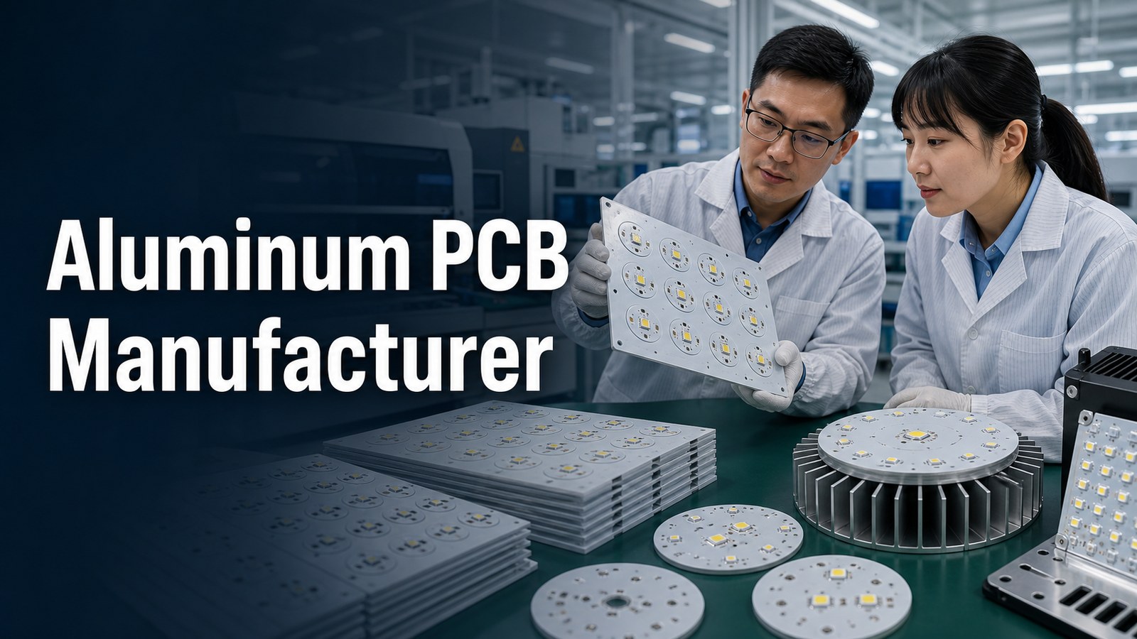
An aluminum PCB manufacturer should help buyers control heat transfer, dielectric selection, copper weight, DFM, assembly and testing before the order is released. Aluminum PCB, also called metal core PCB or MCPCB, is usually chosen when standard FR-4 cannot move heat away from LEDs, power devices or high-current components quickly enough.
EBest Circuit supports aluminum PCB and MCPCB projects by reviewing thermal targets, stackup, base material, copper thickness, surface finish, solder mask, mechanical outline, assembly needs and RFQ files together. The goal is not only to make a board, but to prevent thermal, assembly and reliability problems from appearing after production starts.
Will your aluminum PCB design actually move heat the way the product needs?
Aluminum PCB orders often look simple until thermal, mechanical and assembly details are reviewed together.
- The drawing says aluminum PCB, but the target thermal conductivity, dielectric thickness or heat path is not clearly defined.
- The LED or power component layout creates hot spots that the metal base alone cannot solve.
- Copper weight, hole design, outline tolerance or surface finish is selected before manufacturability is checked.
- The buyer needs assembly, but solder mask color, LED polarity, fixture access, heat sink contact and test requirements are not included in the RFQ.
- The supplier quotes the board without explaining what must be confirmed before thermal performance and delivery risk can be judged.
EBest Circuit helps aluminum PCB buyers check the thermal build before production:
- We review stackup, aluminum or other metal core material, dielectric, copper, board thickness and surface finish before quote assumptions are locked.
- We can discuss MCPCB capability examples including aluminum, copper or stainless steel base materials, 1-10 layer structures and thermal conductivity options such as 1W, 1.5W, 2.0W and 3.0W where the project allows.
- We check DFM details such as line width, spacing, holes, solder mask bridge, outline tolerance, panelization and assembly access.
- We connect aluminum PCB fabrication with PCBA support when buyers need LED mounting, component sourcing, inspection or functional testing.
- We keep capability statements tied to the actual files, material route and quality requirements instead of treating every aluminum PCB as the same order.
What an Aluminum PCB Manufacturer Must Control
An aluminum PCB manufacturer must control the thermal path, metal base, dielectric layer, copper circuit, surface finish, DFM and assembly conditions together.
The metal base helps spread and transfer heat, but it cannot compensate for weak stackup choices, poor LED layout, underspecified dielectric, excessive copper assumptions or missing test criteria. A useful quote should show what is known, what must be confirmed and what may affect cost or production route.
Is Aluminum PCB the Right Choice for Your Project?
Aluminum PCB is a strong choice when the circuit needs better heat spreading than standard FR-4 can provide.
| Project Condition | Aluminum PCB Fit | Buyer Check |
|---|---|---|
| High-power LED or lighting board | Usually strong fit | Check LED heat path, solder mask, surface finish and single-layer MCPCB assembly method |
| Power conversion or driver circuit | Often useful | Check current, isolation, copper and dielectric requirements |
| Low-power signal board | May be unnecessary | Compare FR-4 cost and thermal need first |
| Compact product with heat sink contact | Potentially useful | Confirm mechanical flatness, mounting and interface area |
| Complex multilayer thermal design | Requires careful review | Confirm layer count, via strategy, manufacturability and testing |
Where Aluminum PCBs Are Used
Aluminum PCBs are commonly used in products where heat must move away from the component side and into a metal base or heat sink.
Typical applications include LED lighting, automotive lighting, power modules, power supplies, motor control, industrial electronics, charging products, sensor housings and compact thermal assemblies. The best use case is not just a hot product; it is a product where the board stackup, component layout and enclosure can support a clear thermal path. If routing, thermal spreading or component placement needs both sides of the board, EBest Circuit can also review a double-sided MCPCB route before quoting.
Aluminum PCB and MCPCB Capabilities at a Glance
EBest Circuit can review aluminum PCB and MCPCB builds across metal core material, layer count, board size, copper, line width, hole size and surface treatment requirements.
| Capability Area | Verified Capability Example | RFQ Note |
|---|---|---|
| Base material | Aluminum / copper / stainless steel | Confirm final base material by thermal and mechanical need |
| Thermal conductivity | 1W / 1.5W / 2.0W / 3.0W | Match dielectric and heat path to the product target |
| Layer count | 1-10 layers | Higher complexity requires DFM review |
| Board size | Up to 24*64 inches / 610*1625mm | Confirm panelization, outline and shipping needs |
| Board thickness | 0.6mm to 4.0mm | Confirm heat sink contact and enclosure fit |
| Copper | 0.5oz-10oz | Heavy copper affects spacing, etching and cost |
| Line width / space | 4/4mil (0.10/0.10mm) | Use project files for final DFM check |
| Surface treatment | ENIG, ENEPIG, OSP, HASL LF | Choose by assembly, storage and reliability need |
What Can Go Wrong When Thermal Requirements Are Not Reviewed Early
Thermal risk usually appears when the buyer treats aluminum PCB as a material label instead of a complete heat-transfer design.
Common problems include hot spots under LEDs, insufficient dielectric performance, copper thickness that changes manufacturability, poor contact with the heat sink, solder mask choices that affect visual inspection, and test plans that do not reflect the real operating condition. These issues are easier to fix before the RFQ is approved than after boards are already in production.
How EBest Circuit Helps Buyers Control Aluminum PCB Risk
EBest Circuit helps buyers turn an aluminum PCB request into a controlled manufacturing package.
We review the Gerber or ODB++ files, drawing, stackup, material, copper, thickness, surface finish, solder mask, quantity, PCBA scope and test requirements together. When the project includes assembly, we can connect the board build with PCBA support, component sourcing, inspection and functional test planning.
Need an aluminum PCB quote with thermal and DFM review?
Send Gerber or ODB++ files, stackup, thermal target, copper, surface finish, BOM, quantity and assembly needs. EBest Circuit can review the MCPCB build path before production starts.
Thermal target | MCPCB | DFM | PCBA | RFQ planning
Aluminum PCB Stackup and Thermal Path
An aluminum PCB stackup usually transfers heat from the component and copper circuit through the dielectric layer into the aluminum base.
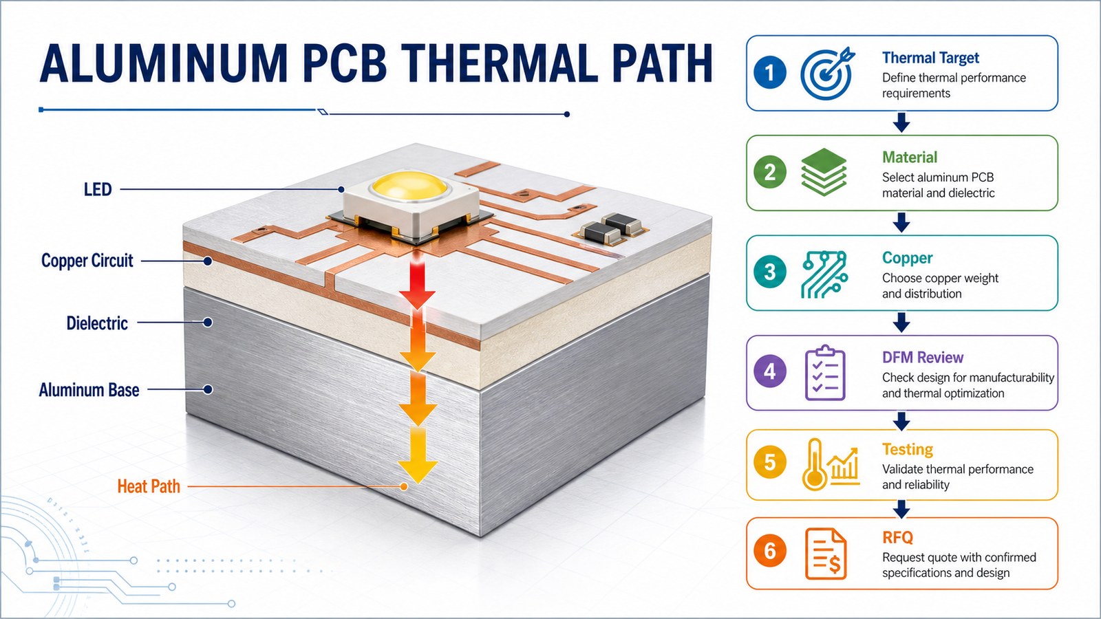
The dielectric layer is critical because it must provide electrical insulation while allowing heat transfer. The aluminum base then spreads heat into the mechanical structure or heat sink. The RFQ should state the thermal target, component location, copper weight, dielectric requirement and mechanical contact area when these details are important.
Aluminum PCB Manufacturing Process
The aluminum PCB manufacturing process should begin with file review and thermal stackup confirmation before fabrication starts.
A practical process includes file check, material and dielectric confirmation, copper pattern manufacturing, drilling or routing, solder mask, surface finish, electrical inspection, mechanical checks and packaging. If the article topic comes from process-related demand, the useful answer is not just a list of steps; it is an explanation of where each step can change heat transfer, assembly quality or delivery risk.
Material, Dielectric and Thermal Conductivity Options
Material and dielectric choices determine whether an aluminum PCB can support the product’s heat and insulation requirements.
For MCPCB projects, EBest Circuit can review aluminum, copper or stainless steel base requirements and thermal conductivity options such as 1W, 1.5W, 2.0W and 3.0W when the project route supports them. Buyers should define whether the main priority is heat transfer, insulation, cost, mechanical strength, board thickness or assembly reliability.
Copper Thickness, Line Width, Holes and Board Size
Copper thickness, spacing, hole design and board size affect both thermal performance and manufacturability.
Capability examples include 0.5oz-10oz conductor thickness, 4/4mil line width and space, 0.25mm minimum hole diameter and large-format boards up to 610*1625mm. These values still require project review because copper, outline, hole spacing, solder mask and panelization interact with each other.
Surface Finish, Solder Mask and LED Assembly Considerations
Surface finish and solder mask choices should be selected around assembly, visual inspection, storage and reliability needs.
Common surface treatment options include ENIG, ENEPIG, OSP and lead-free HASL. LED aluminum PCB projects may also need careful attention to solder mask color, reflectivity, polarity marks, component spacing, heat sink contact, fixture access and post-assembly inspection.
Aluminum PCB Assembly and Component Sourcing
Aluminum PCB assembly should be planned together with fabrication when the project includes LEDs, drivers, connectors or power components.
Send BOM, CPL, assembly drawings, polarity notes, approved alternates and test requirements with the PCB files. EBest Circuit can connect aluminum PCB fabrication with prototype PCB assembly and production planning when the buyer wants a PCB + PCBA route instead of bare boards only.
Testing, Inspection and Quality Control
Testing and inspection for aluminum PCB should confirm both electrical quality and the build assumptions that affect thermal reliability.
Depending on the project, checks may include visual inspection, electrical test, AOI, dimensional inspection, solderability review, assembly inspection and functional testing. If the finished product has thermal acceptance criteria, buyers should state how the board will be tested in the final product or fixture.
Cost and Lead-Time Factors for Aluminum PCB Orders
Aluminum PCB cost and lead time depend on material, dielectric, thermal target, copper, board size, finish, assembly scope and test requirements.
| Factor | Why It Changes the Quote | What to Send |
|---|---|---|
| Thermal target | Defines dielectric and material route | Power, LED data, heat path and operating conditions |
| Base material | Aluminum, copper and stainless steel have different cost and processing needs | Preferred material and acceptable alternatives |
| Copper | Heavy copper affects etching, spacing and cost | Copper weight and current requirements |
| Surface finish | Affects assembly, storage and reliability | ENIG, ENEPIG, OSP, HASL LF or project preference |
| PCBA scope | Components, stencil, assembly and test add schedule work | BOM, CPL, assembly drawing and test scope |
Ready to compare an aluminum PCB manufacturing plan?
EBest Circuit can review the thermal stackup, metal core material, copper, finish, PCBA and testing requirements before you approve the build.
Aluminum PCB | MCPCB | LED boards | PCBA | Test planning
How to Evaluate an Aluminum PCB Manufacturer
An aluminum PCB manufacturer should be evaluated by thermal engineering support, MCPCB capability, DFM response, assembly support and quote clarity.
- Can the supplier explain the thermal path, dielectric and base material assumptions?
- Can it support the layer count, copper, thickness, hole and surface finish requirements?
- Does it review DFM before production starts?
- Can it support both bare aluminum PCB and PCBA if the project needs assembly?
- Does the quote define inspection, testing, packaging and open engineering questions?
RFQ Checklist for Aluminum PCB Manufacturing
A clear aluminum PCB RFQ should give the manufacturer enough information to judge thermal, manufacturing and assembly risk.
- Gerber or ODB++ files, drill files and fabrication drawing
- Stackup, base material, dielectric, thermal conductivity target and board thickness
- Copper weight, surface finish, solder mask color and outline requirements
- Quantity, revision, target application and target delivery needs
- BOM, CPL, assembly drawing and component alternates if PCBA is required
- Electrical test, functional test, thermal test or packaging requirements
FAQ About Aluminum PCB Manufacturers
What is an aluminum PCB manufacturer?
An aluminum PCB manufacturer builds metal core printed circuit boards that use an aluminum base to help transfer heat away from LEDs, power components or other heat-generating devices.
Is aluminum PCB the same as MCPCB?
Aluminum PCB is a common type of MCPCB. MCPCB means metal core PCB and may use aluminum, copper or another metal base depending on the project.
What files are needed for an aluminum PCB quote?
Send Gerber or ODB++ files, drill files, stackup, base material, dielectric requirement, copper, surface finish, quantity, thermal target and assembly files if PCBA is needed.
Can aluminum PCB include assembly?
Yes. Aluminum PCB can include assembly, but BOM, CPL, LED polarity, component availability, test requirements and heat sink interface details should be reviewed early.
Need an aluminum PCB manufacturer for LED, power or thermal electronics? Send your Gerber or ODB++ files, stackup, base material, thermal target, copper, surface finish, BOM, CPL, quantity and test requirements to sales@bestpcbs.com. EBest Circuit can review MCPCB manufacturability, thermal design risk, PCBA needs and quote assumptions before production starts.
You may also like


Tags: aluminum pcb, MCPCB, PCB Quote