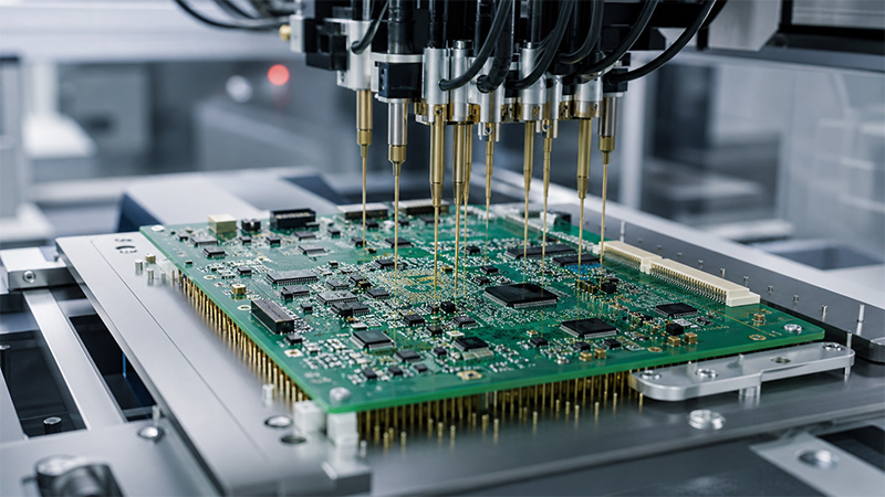
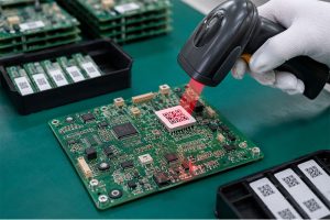
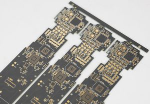
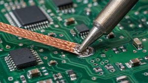
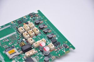
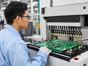
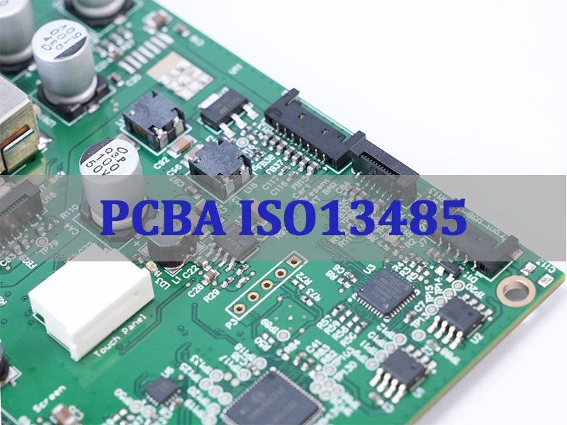
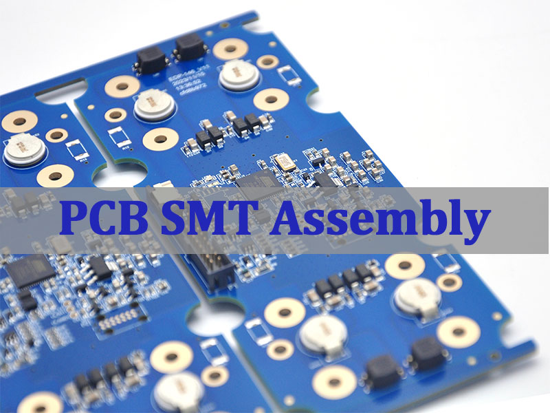
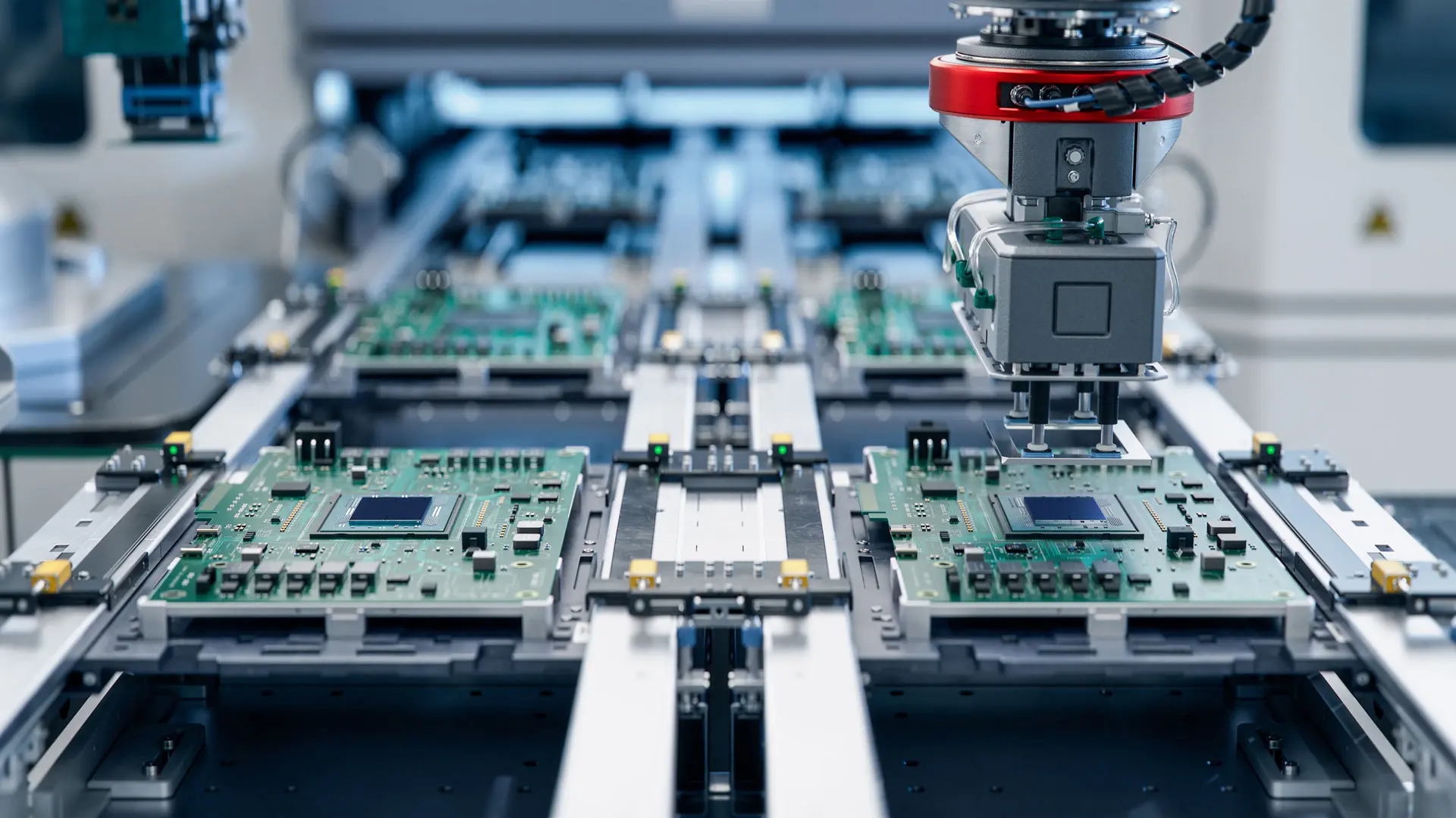
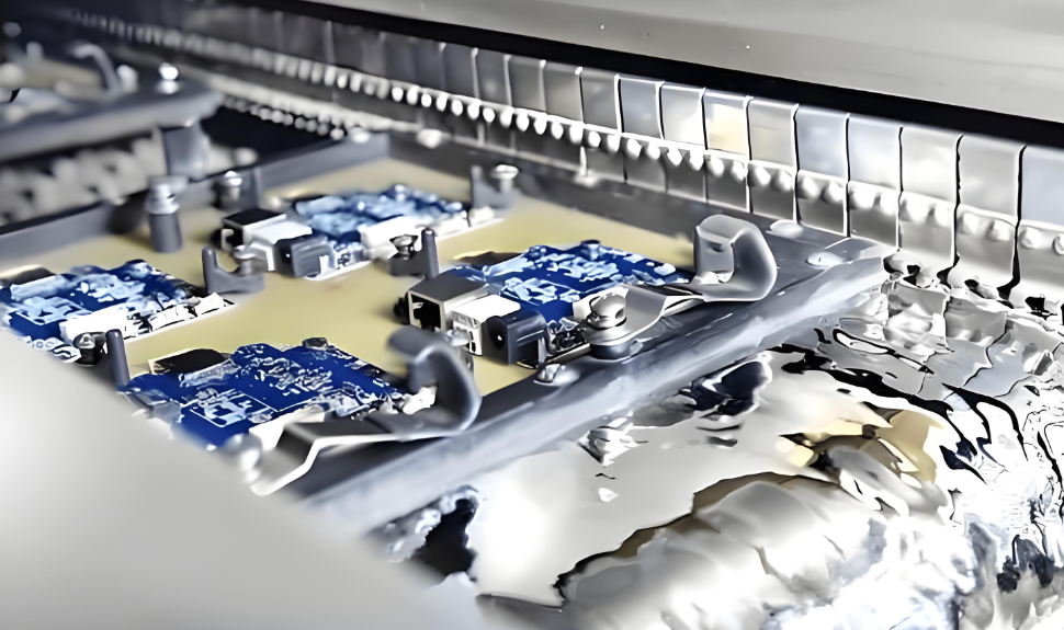
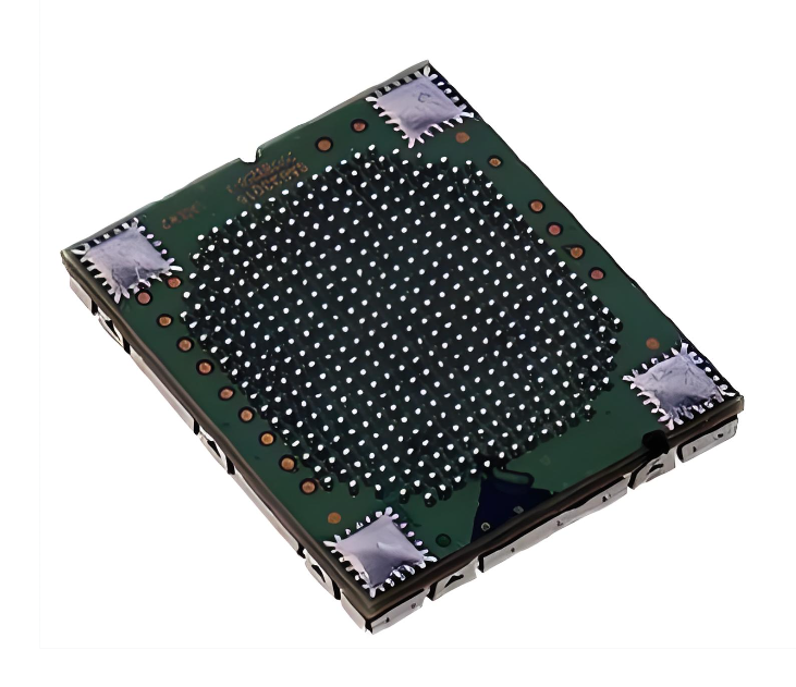
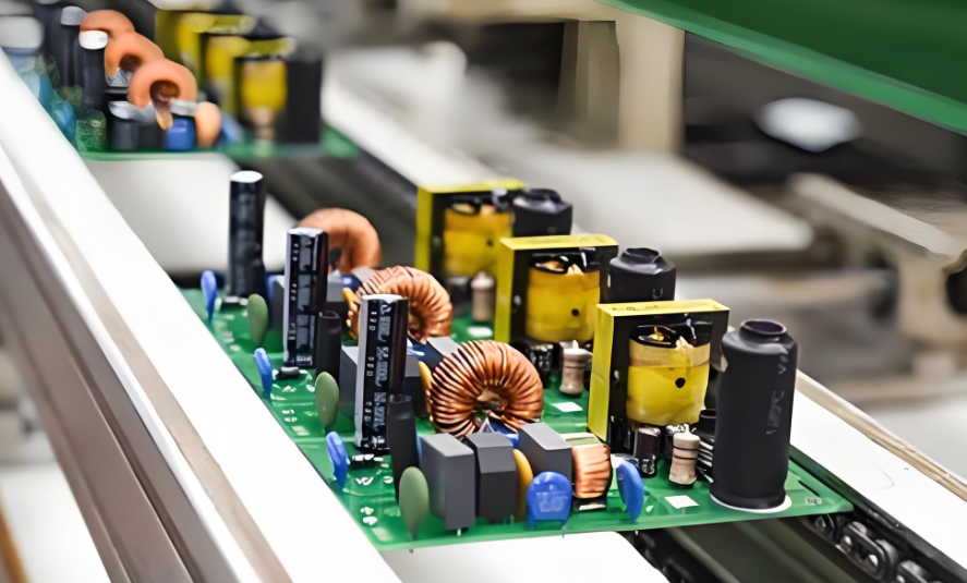
Through-Hole Assembly remains a critical manufacturing method for electronics that demand strong mechanical connections and long-term reliability. In this guide, you will learn how through hole pcb assembly works, when to use it, and how to choose the right through hole pcb assembly service for your project.
What Is Through-Hole Assembly and Why Is It Still Essential?
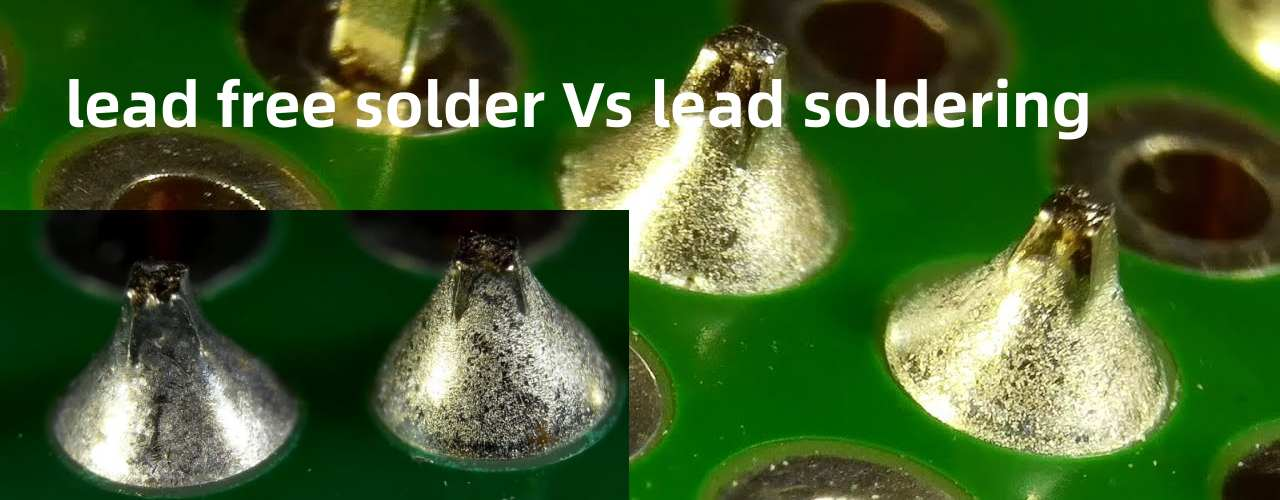
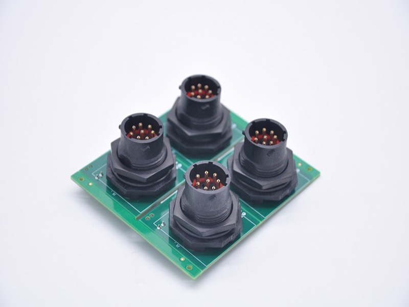
Through-hole assembly refers to inserting component leads into drilled holes on a PCB and soldering them on the opposite side, which creates a strong and stable mechanical bond. Compared with surface mount technology, this method offers better durability, especially in applications exposed to vibration, heat, or high electrical load.
Although SMT dominates consumer electronics, through-hole pcb assembly is still widely used in industrial, aerospace, and automotive sectors. The reason is simple: reliability matters more than size in these environments, and through-hole connections are much harder to fail under stress.
What Are the Advantages of Through-Hole PCB Assembly?
Through hole assembly services continue to be preferred in many industries, because they offer several practical advantages that SMT alone cannot fully replace.
Strong mechanical bonding for heavy or large components
Better resistance to vibration and thermal cycling
Higher reliability in high-current and high-voltage circuits
Easier inspection, repair, and rework
Suitable for connectors, transformers, and power components
Because of these benefits, many designs still combine SMT and through hole pcb assembly to achieve both compact size and strong reliability.
What Types of Through-Hole Assembly Services Do We Offer?
A professional through hole pcb assembly service should cover different production needs, from low-volume prototypes to large-scale manufacturing. At EBest Circuit, we provide flexible and scalable solutions to match different project requirements.
Manual through hole assembly for complex or low-volume boards
Automated through hole assembly for high-volume production
Mixed technology assembly (SMT + THT)
Wave soldering and selective soldering
Full turnkey service including PCB fabrication and component sourcing
By integrating all processes into one workflow, we help reduce lead time and improve overall production efficiency.
Through Hole Assembly Process – Step-by-Step Overview
The through hole assembly process follows a structured workflow, and each stage must be controlled carefully to ensure consistent quality.
1. Component preparation and lead forming, ensuring proper fit for insertion
2. PCB drilling and plating, creating reliable conductive holes
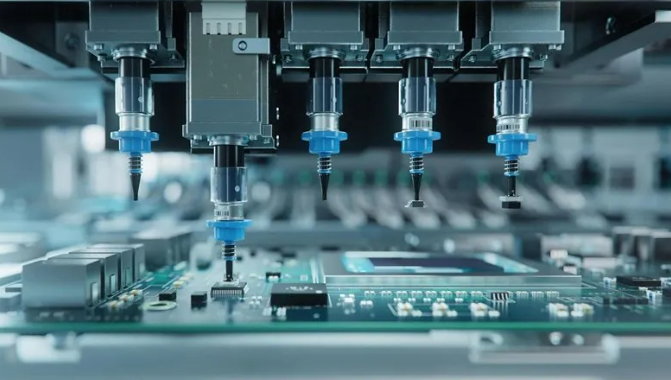
3. Component insertion, either manually or using automated machines
4. Soldering, typically through wave soldering or selective soldering
5. Cleaning, removing flux residues when required
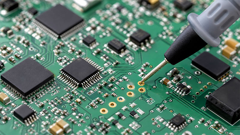
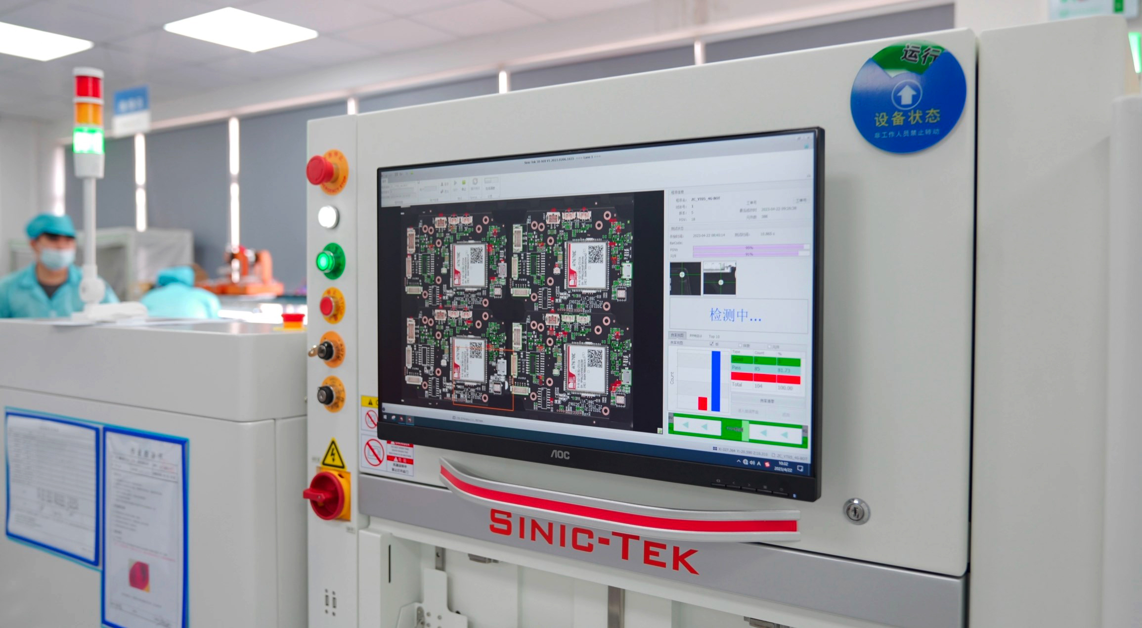
6. Inspection, including AOI, X-ray, and visual checks
Each step plays a role in ensuring that the final product meets both mechanical and electrical requirements.
What Equipment Is Used in Through-Hole PCB Assembly?
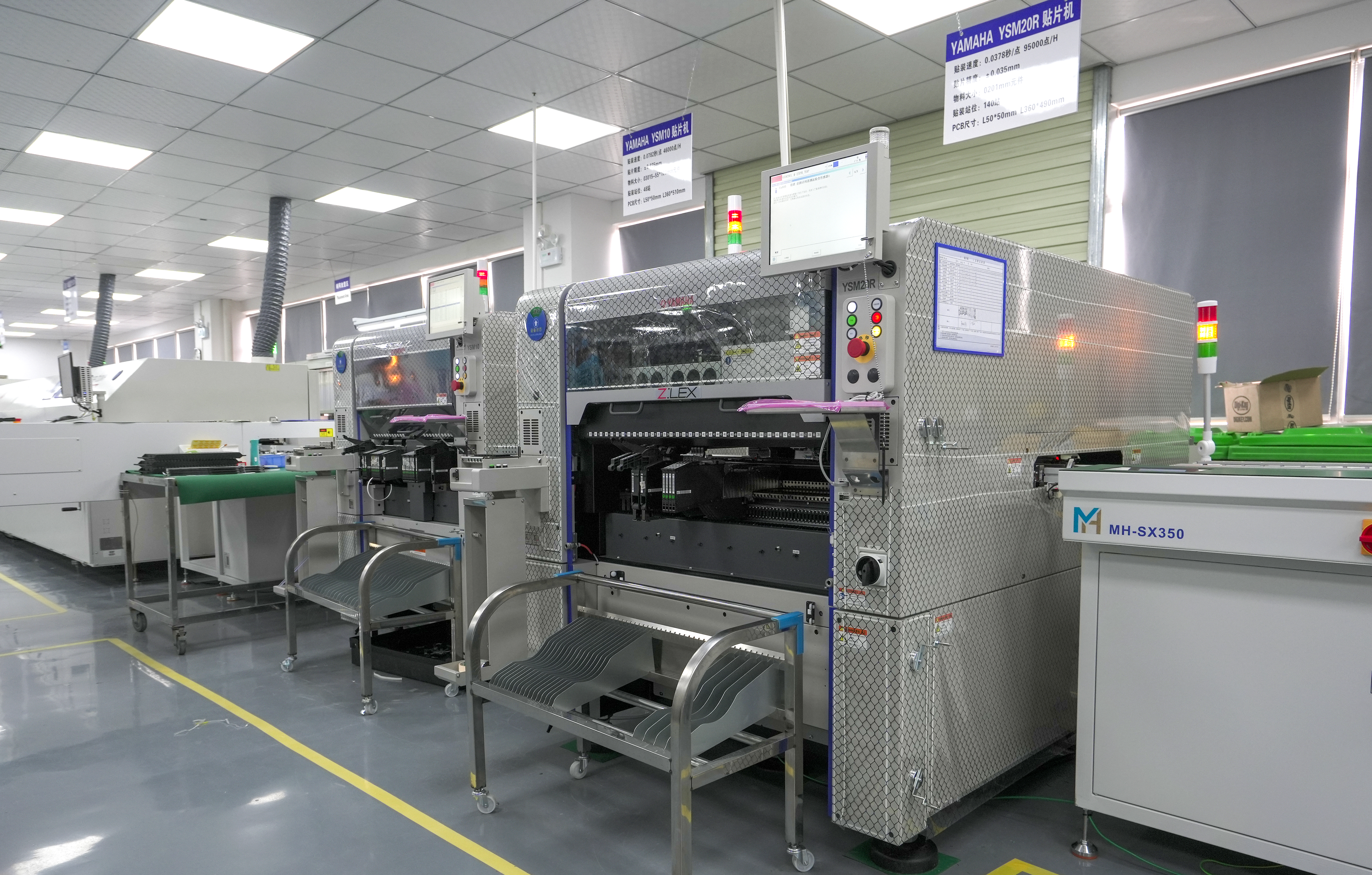
Modern through hole pcb assembly equipment helps improve efficiency and consistency, especially in large-scale production.
Automated insertion machines for axial and radial components
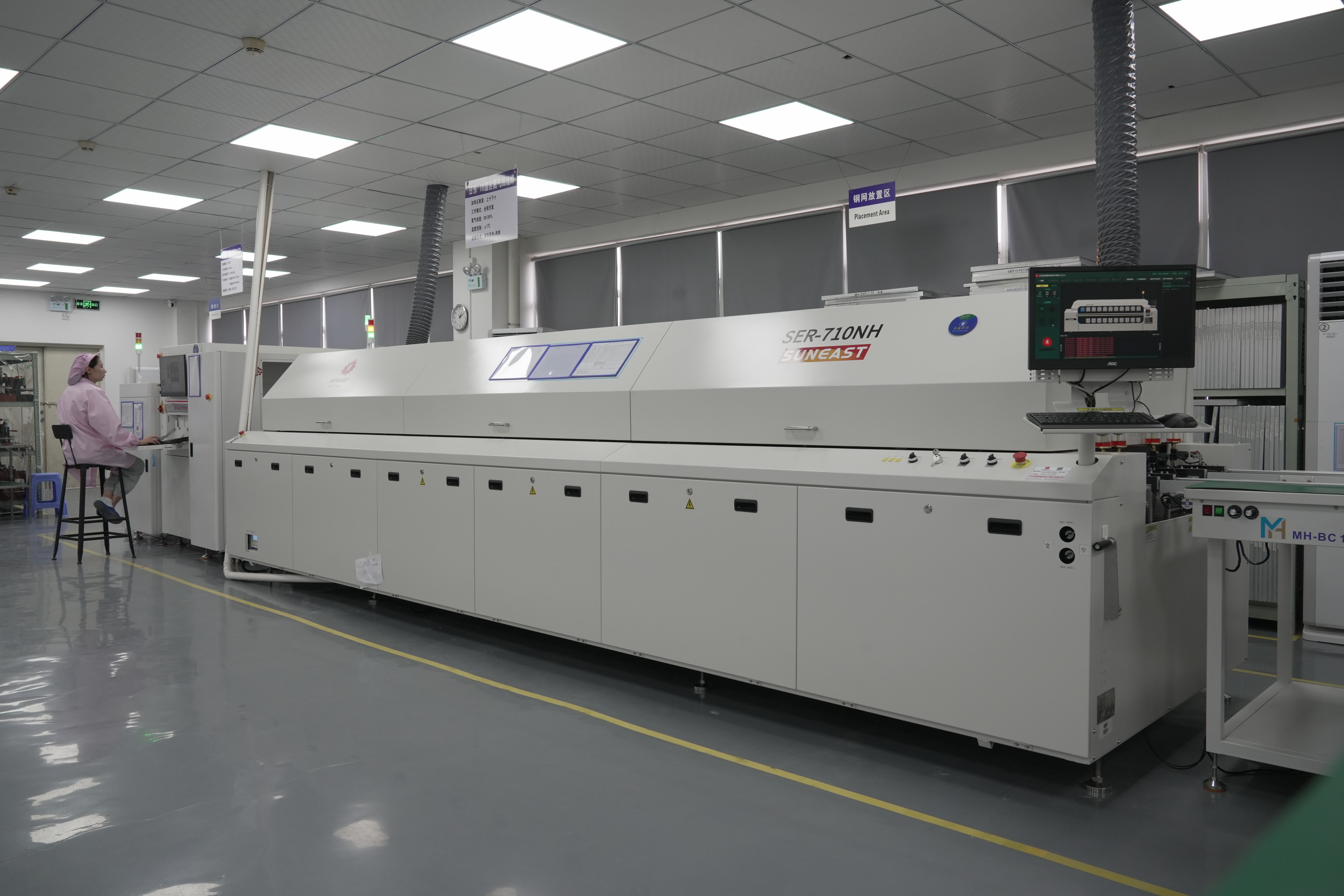
Wave soldering systems for high-speed production
Selective soldering machines for precision soldering
AOI and X-ray systems for quality inspection
With the right equipment, manufacturers can achieve both high yield and stable performance across batches.
Automated Through Hole Assembly vs Manual Assembly – Which to Choose?
Choosing between automated through hole assembly and manual assembly depends on production volume and design complexity.
Type
Automated Through Hole Assembly
Manual Through Hole Assembly
Efficiency
High
Lower
Cost
Lower at scale
Higher
Flexibility
Limited
High
Best for
Mass production
Prototypes and complex boards
When Should You Choose Through-Hole PCB Assembly Instead of SMT?
While SMT is efficient for compact designs, there are situations where through hole pcb assembly is the better choice.
When components require strong mechanical support
When the circuit operates under high current or voltage
When the product will face vibration or harsh environments
When long-term reliability is more important than size
Understanding these scenarios helps engineers make better design decisions early in the project.
Why Choose EBest Circuit for Through Hole PCB Assembly Service?
Selecting the right manufacturing partner is just as important as choosing the right technology. EBest Circuit offers a complete solution for through hole pcb assembly, backed by strong engineering and manufacturing capabilities.
Over 20 years of PCB and PCBA manufacturing experience
One-stop service from PCB fabrication to final assembly
Certified quality system including ISO9001, ISO13485, IATF16949, and AS9100D
Multiply PCB types, including MCPCB, high speed PCB, RF PCB, ceramic PCB, rigid flex pcb…
With a focus on quality and customer support, EBest helps reduce risks and improve project success rates.
Which Industries Use Through-Hole Assembly the Most?
Through hole pcb assembly remains essential in industries where durability and reliability are critical.
Industrial control systems
Automotive electronics
Aerospace and defense
Power supply and energy systems
Medical equipment
As electronic systems become more complex, these industries continue to rely on through-hole technology for critical components.
Common Challenges in Through Hole PCB Assembly and How to Solve Them
Like any manufacturing process, through hole assembly comes with challenges, but most of them can be addressed with the right approach.
Common challenges include:
Inconsistent solder joints
Component misalignment
High labor cost
Difficulty in automation for complex designs
Effective solutions include:
Using selective soldering for precision control
Optimizing PCB layout for easier insertion
Combining SMT and THT technologies
Working with experienced manufacturers
By addressing these issues early, manufacturers can improve both yield and reliability.
FAQ About Through-Hole Assembly
What is the difference between through hole pcb assembly and SMT?
Through hole assembly uses inserted leads, while SMT mounts components directly on the surface, resulting in different mechanical strength and application use.
Is through hole assembly still used today?
Yes, it is still widely used in high-reliability applications such as aerospace, industrial systems, and power electronics.
Can through-hole and SMT be combined on one PCB?
Yes, many designs use a mixed assembly approach to balance performance and cost.
What is automated through hole assembly?
It refers to using machines to insert components and improve efficiency in high-volume production.
Ready to Start Your Through-Hole PCB Assembly Project?
If you are looking for a reliable through hole pcb assembly service, EBest Circuit is ready to support your project with strong engineering expertise and fast delivery.
Feel free to contact us at sales@bestpcbs.com to discuss your requirements and get a quick quotation.
Struggling to find reliablelow volume PCB assembly for small-batch projects? For teams navigating small-batch electronic production, consistent, high-quality low volume PCB assembly is often the biggest roadblock between prototype testing and full market launch.
EBest Technology delivers targeted low volume PCB assembly solutions to eliminate this gap entirely, with zero compromise on quality or speed. As a China-based professional manufacturer with 19+ years of dedicated PCBA expertise, we specialize in small-volume, prototype-focused assembly that skips strict mass-production minimums. We maintain strict quality controls and support fast turnaround for critical projects across medical, aerospace, and industrial equipment sectors. And we cut unnecessary delays and hidden costs, focusing on functional, compliant small-batch PCBA that meets global industry standards reliably.
What Are Low Volume PCB Assembly Services?
Low volume PCB assembly refers to specialized printed circuit board assembly services designed for small production runs, typically ranging from single prototype units to low thousands of finished boards, filling the critical gap between initial prototype development and full-scale mass manufacturing. Unlike mass production facilities that enforce high minimum order quantities (MOQs) and prioritize large-batch efficiency, this service caters to niche product testing, custom industrial equipment builds, medical device validation, aerospace component prototyping, and small-market product launches.
This targeted assembly model supports flexible order sizes, personalized production adjustments, and rigorous quality checks for every unit, making it ideal for projects that require precision, compliance, and speed without the expense of large-scale production. Every long tail keyword tied to small-batch assembly aligns with this core definition, including prototype PCB assembly services low volume and small volume PCB assembly.
Stuck Between Prototype and Mass Production? Our Services Are the Solution.
Finding reliable low volume PCB assemblyis critical for bridging prototype and mass production. EBest provides targeted solutions for small-batch projects, with no high MOQs, strict quality controls, and fast turnaround. We serve medical, aerospace, and industrial equipment sectors, ensuring compliant, high-quality boards without unnecessary delays or hidden costs. Our in-house fabrication and component sourcing eliminate external supply chain risks, supporting seamless scaling from validation to limited production runs.
As a leading low volume PCB assembly manufacturer in China, EBest stands out with 19+ years of expertise, global certifications (ISO 13485, AS9100D, IATF 16949) and advanced automation. We offer a full range of services: prototype assembly, quick-turn solutions, full turnkey support, precision BGA, through-hole, flex/rigid-flex, and ceramic PCB assembly. Our capabilities include 13.2 million chips daily placement, 1-5 day standard lead times, and 24-hour rush service, with 100% full inspection before shipment. We also provide cost-saving strategies, such as consolidating small orders and using standard components, to optimize budgets without compromising quality.
Is Your Budget Tight? How to Save on Small Volume PCB Assembly?
Tight budgets often derail low volume circuit board assembly projects, from prototype validation to small-batch medical and industrial runs. Most teams overspend by 25%-35% on small orders, thanks to unoptimized workflows, hidden setup fees, and inflated middleman markups that punish low-quantity buyers.
Even small, one-off prototype batches face unfair premium pricing, and these extra costs quickly eat into project budgets and delay product development timelines for niche and specialized electronic builds.
As a professional China low volume PCB assembly factory, EBest cuts your total low volume PCB assembly costs by 20%-40% compared to standard manufacturers, with clear, actionable cost-saving methods. Our in-house PCB fabrication and direct component supply chain remove middleman fees entirely, slashing material and sourcing costs by 15%-20% for small batches.
We also optimize production setup and panelization for small orders, cutting per-unit setup and labor expenses by another 10%-20%, so you pay fair prices even for tiny batch sizes with no hidden charges.
We never sacrifice quality to lower costs, our streamlined small-batch workflows reduce waste and redundant steps, not performance. We offer free design-for-manufacturing (DFM) checks to avoid costly reworks, which can save you an extra 10%-15% on post-production fixes.
Our consistent, defect-controlled assembly also eliminates costly replacement orders, letting you stay within budget while getting reliable, production-ready boards for medical, aerospace, and industrial applications.
Does Low Volume Mean Lower Quality? Ensuring Excellence in Every Batch.
A common misconception about low volume PCB assembly services is that small batches mean lower quality standards, and this worry often stalls critical small-batch projects. At EBest, we eliminate this concern with strict, repeatable production controls and data-backed quality performance, tailored specifically for low volume and prototype orders.
We treat every small-batch order with the same rigorous process discipline as high-volume runs, with standardized operating procedures for every assembly step, no matter how small the order quantity. Our 19+ years of PCBA experience lets us lock in consistent quality without cutting corners or rushing production for quick turnaround.
We run full incoming material inspections for every batch, verifying raw PCB substrate quality and component authenticity before assembly starts. We only use A-grade, wear-resistant materials, and reject any subpar incoming parts to prevent defects early in the process.
Our automated SMT placement equipment runs calibrated precision checks before each batch, maintaining consistent placement accuracy even for tiny 01005 SMD components and 0.25mm pitch BGA packages. This machine calibration eliminates human error and ensures uniform quality across every unit.
We enforce 100% full inspection on every assembled board before shipment, including automated optical inspection (AOI), soldering integrity checks, and functional performance testing where required. Our quality data confirms a defect rate of less than 0.3% for all low volume batches, matching the reliability of large-scale production.
Defective units are immediately isolated and reworked or scrapped, with zero substandard boards leaving our facility. We also conduct post-assembly stability checks for boards used in high-demand environments, ensuring long-term durability.
Our low volume assembly has been validated for real-world use across medical diagnostic tools, aerospace control components, and heavy-duty industrial equipment. These applications demand consistent, reliable performance, and our small-batch boards pass field testing and operational stress checks without quality gaps.
This track record proves low volume assembly never means lower quality, it simply means targeted, precise production that prioritizes consistency and reliability for your specialized, small-scale projects.
Urgent Need Assembled Boards? How We Accelerate Your Low Volume PCB Assembly
Missed deadlines for small-batch PCB orders can derail your entire project timeline, push back product launches, and even disrupt critical emergency operations. That’s why PCB assembly low volume orders need fast, dependable turnaround you can count on, not vague delivery promises.
EBest’s dedicated expedited production system delivers on urgent requests reliably: we can ship fully assembled, inspected boards within 24 hours for your most time-sensitive projects. Our in-house PCB fabrication and component sourcing teams cut out third-party delays entirely, and our automated assembly lines speed up processing without sacrificing placement precision or soldering quality.
For most standard low volume projects, our regular lead time is just 1–5 business days, far faster than industry averages for small-batch assembly. We’ve supported countless urgent requests: emergency medical device repairs, tight aerospace prototype testing windows, and last-minute industrial equipment replacement parts, helping clients hit critical deadlines without compromising on board quality.
Struggling with Parts? Our Component Sourcing for Circuit Board Assembly.
Few hurdles slow down low volume PCB assembly projects more than frustrating component sourcing struggles. Most buyers face endless hours hunting for small-batch parts, steep price markups for low-quantity orders, strict supplier MOQs that block small purchases, and constant fear of counterfeit or low-quality components derailing production entirely.
These roadblocks don’t just waste time, they push back project deadlines, inflate total costs, and create unnecessary stress for critical small-batch builds, from medical device prototypes to aerospace test components and industrial equipment replacements.
At EBest, we eliminate every one of these pain points with our dedicated, full-coverage component sourcing service, built exclusively to support low volume PCB assembly services and small-batch production needs. We take the entire parts procurement burden off your plate, so you can focus on project progress instead of supply chain headaches.
Our global, stable component supply chain covers every standard and specialty part you need, including SMD, BGA, QFN, QFP, and through-hole components, with no unfair small-order penalties. We vet every supplier rigorously to guarantee 100% authentic, high-quality components, eliminating counterfeit risks entirely for your sensitive industrial, medical, and aerospace projects.
We also leverage our 19+ years of industry partnerships to lock in competitive pricing for low-quantity parts, cutting your component costs by up to 20% compared to independent sourcing. No more haggling, no more delayed deliveries, and no more stalled production, just reliable, timely, cost-effective parts that keep your low volume PCB assembly project on track and on budget, from start to finish.
Why is a China-Based Factory Like EBest Your Best Choice?
Choosing a trustedlow volume PCB assembly manufacturer in China means accessing cost efficiency, advanced technology, and global compliance, and EBest stands out as a leader with 19+ years of specialized experience. Below are the core advantages that make us the best partner for your small-batch PCBA needs:
19+ years of dedicated PCB and PCBA manufacturing expertise, serving global clients across medical, aerospace, and industrial sectors
Full suite of global quality certifications (IATF 16949, ISO 9001, ISO 13485, AS9100D, RoHS, UL) for regulatory compliance.
In-house PCB fabrication and component sourcing, offering full turnkey solutions to streamline production.
No high MOQs, catering specifically to prototype, low volume, and small-batch assembly projects.
Advanced automated assembly equipment with 13.2 million chips daily placement speed for precision and speed.
100% full inspection on every assembled board before shipment, zero quality shortcuts for small batches.
Expedited 24-hour rush service for urgent low volume orders, with standard 1-5 day lead times.
Monthly production capacity of 260,000 square feet, handling over 1,000 unique board designs monthly.
Customizable substrate and material options for ceramic, flex, rigid-flex, and high-frequency PCBs.
Dedicated personalized support team for every client, with end-to-end project tracking and transparency.
What Types of Low Volume PCB Assembly Services Does We Offer?
EBest offers a complete portfolio of low volume pcb assembly services to cover every small-batch and prototype need, with specialized support for unique board types and assembly requirements. Below are types of low volume PCB assembly services we offer you:
Prototype PCB Assembly: Custom prototype builds for design validation, testing, and regulatory approval across medical and aerospace industries.
Quick Turn PCB Assembly: Fast-turnaround small-batch assembly for urgent project deadlines and emergency replacement parts.
Full Turnkey PCB Assembly: End-to-end service including PCB fabrication, component sourcing, assembly, and full inspection.
BGA Assembly: Precision BGA assembly with 0.25mm minimum pitch, ideal for high-density industrial and aerospace electronics.
Through-Hole Assembly: Reliable through-hole component assembly for rugged industrial equipment and high-durability applications.
Flex & Rigid-Flex PCB Assembly: Specialized assembly for flexible circuit boards used in medical devices and compact aerospace components.
Ceramic PCB Assembly: High-temperature ceramic PCB assembly for industrial and aerospace applications with extreme operating conditions.
Box Assembly: Complete box build assembly with full automation and final inspection, ready for immediate deployment.
13,200,000 chips per day (automated precision placement)
Bare Board Size Range
0.2″ x 0.2″ to 22″ x 47.5″
Minimum SMD Component
01005 (ultra-small component support)
Minimum BGA Pitch
0.25mm (high-density BGA assembly capability)
Max Component Size
50mm x 150mm
Assembly Types
SMT, Through-Hole (THT), Mixed SMT+THT Assembly
Component Packaging
Reels, Cut Tape, Tube, Tray, Loose Parts
Standard Lead Time
1-5 business days; 24-hour rush service available
How to Get a Quote for Your Small Volume PCB Assembly Project?
Securing a customized quote for your low volume PCB assembly project is simple and fully transparent with EBest. We’ve built a streamlined 4-step process to deliver accurate, fast pricing with zero hidden fees, so you know exactly what to expect before starting production. Follow these clear steps to launch your project smoothly:
Submit Project Details: Send your complete PCB design files, including Gerber files, BOM list, and assembly drawings. Be sure to note your target order quantity, required lead time, and any special needs like unique substrate materials or custom assembly specs.
Project Review & Feasibility Check: Our experienced production team reviews your design thoroughly, verifies component availability, and spots potential optimizations to improve quality or cut extra costs —no extra charge for this pre-production check.
Custom Quote Delivery: We send a detailed, fixed quote that covers every cost: PCB fabrication, component sourcing, assembly, full inspection, and shipping. There are no surprise fees or added charges later, keeping your budget on track.
Confirm Order & Start Production: Once you approve the quote and confirm all details, we immediately start production with full transparency, sending regular progress updates so you stay informed every step of the way.
Ready to get a hassle-free, customized quote for your low volume PCB assembly project? Don’t let budget uncertainty or project delays hold you back. Send us your project details today at sales@bestpcbs.com, and our team will respond quickly with a fair, detailed quote tailored to your needs. Whether you need prototype assembly, small-batch production, or urgent quick-turn services, we’re here to help you save costs, hit deadlines, and get reliable, high-quality boards every time.
FAQs About Low Volume Circuit Board Assembly
Q1: What is the minimum order quantity for low volume PCB assembly at EBest? A1: We accept single prototype units, small-batch runs of 10-50 units, and mid-range low-volume orders up to a few thousand units. We cater specifically to clients who need small quantities without the high MOQs required by mass production manufacturers, making us ideal for prototype testing and niche product builds.
Q2: Are low volume PCB assembly orders subject to the same quality checks as high-volume orders? A2: Yes, every low volume PCB assembly order undergoes 100% full inspection before shipment, including automated optical inspection (AOI), soldering quality checks, and functional testing where required. We follow the same certified quality protocols for all orders, regardless of size, and hold global certifications to ensure compliance for medical, aerospace, and industrial projects.
Q3: How long does it take to complete a standard low volume PCB assembly order? A3: Our standard lead time for low volume PCB assembly is 1-5 business days from order confirmation. For urgent, time-critical projects, we offer a 24-hour expedited service for qualified small-batch orders, ensuring you receive finished boards exactly when you need them for testing or deployment.
Q4: Can you handle specialized PCB materials for low volume assembly? A4: Absolutely, we support a full range of specialized PCB substrates and materials for low volume assembly, including FR4, ceramic, flex, rigid-flex, metal-based (MCPCB), and high-frequency materials. We customize substrate selection to match your project’s application, whether it’s high-temperature industrial equipment, compact medical devices, or aerospace-grade electronics.
Q5: Do you provide component sourcing for low volume orders with hard-to-find parts? A5: Yes, our dedicated component sourcing team has a global, stable supply chain to source standard, specialized, and hard-to-find electronic components for low volume orders. We avoid counterfeit parts, secure competitive pricing even for small component quantities, and eliminate the hassle of independent parts procurement for your team.
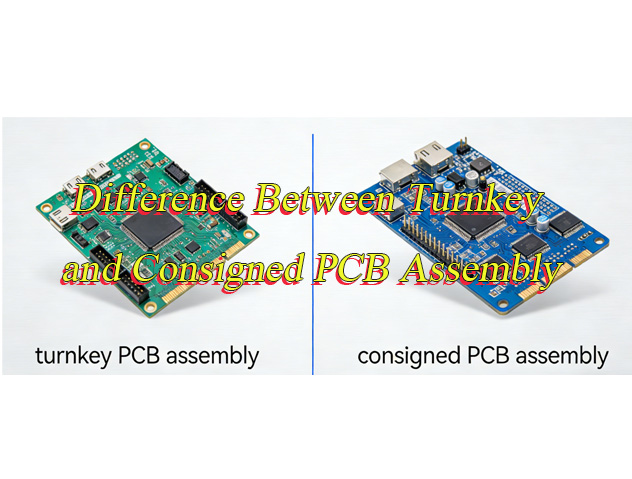
Struggling to understand howconsigned PCB assembly differs from turnkey and which one saves you money? This guide compares definitions, costs, service scopes, lead times, risks, and supplier choices to help you optimize your PCB decisions efficiently.
What is Consigned PCB Assembly?
Consigned PCB assemblyrefers to a service where the client provides all necessary components (such as resistors, capacitors, ICs, and PCBs), and the manufacturer is responsible for assembling these components into finished PCBs according to the client’s specifications. This model puts the client in control of component sourcing, while the manufacturer handles the assembly process, quality testing, and packaging.
A reputable consignment PCB assembly supplier will verify component quality upon receipt, ensure proper storage to prevent damage, and follow strict assembly protocols to meet the client’s requirements. This model is ideal for clients who have established component supply chains or need to use specific, high-quality components for their products.
What is Turnkey PCB Assembly?
Turnkey PCB assembly is a full-service solution where the manufacturer takes complete responsibility for the entire PCB production process. This includes component sourcing, procurement, assembly, testing and delivery. Clients only need to provide the design files (Gerber files, BOM list) and specifications, and the manufacturer handles the rest.
This model eliminates the need for clients to manage component sourcing. It reduces administrative burdens and potential supply chain risks, making turnkey solutions popular among businesses that want to streamline their production process and focus on core operations instead of component management.
Difference Between Turnkey and Consigned PCB Assembly
Comparison Aspect
Turnkey PCB Assembly
Consigned PCB Assembly
Material Procurement
Manufacturer handles all component sourcing
Client supplies components
Cost Structure
Higher upfront cost but lower total cost (bulk buying, logistics savings)
Lower material costs but higher management/labor costs
Lead Time
Typically shorter (manufacturer controls supply chain)
Varies based on client’s supply chain efficiency
Risk Allocation
Manufacturer bears sourcing/quality risks
Client bears component quality/supply risks
Quality Control
Manufacturer-managed (integrated process)
Shared responsibility (client controls part quality)
Flexibility & Customization
Limited (predefined specs)
High (client can modify materials/processes)
Volume Efficiency
Optimal for large-scale production
Better for small batches/specialty items
Client Expertise Required
Minimal (relies on manufacturer)
High (requires sourcing/inventory management skills)
Supply Chain Control
Manufacturer-managed
Client-controlled
Total Cost of Ownership
Often lower (logistics/bulk savings offset fees)
Potentially higher (inventory/management costs)
Cost Analysis: Is Consigned PCB Assembly More Economical for Small Businesses?
For international small businesses, cost control directly affects operational sustainability. Unlike turnkey solutions, consigned PCB assembly eliminates manufacturer sourcing markups, cutting direct costs significantly. This is a game-changer for budget-conscious small businesses, especially those leveraging regional trade agreements, as sourcing components locally or from preferential regions can slash tariff costs by up to 60% in some cases, and you retain full control over component pricing to negotiate bulk discounts with trusted suppliers, critical for reducing per-unit costs on small to medium production runs.
However, hidden costs can erode savings if you lack an established component supply chain. These include international shipping fees, customs delays, and rework costs from low-quality components; for example, urgent component shipping or rework for defective parts can add 15-30% to your total costs, negating initial assembly savings from consigned services, especially when navigating complex global trade rules and supply chain gaps.
The key to cost efficiency lies in your component supply chain: if you have reliable local or regional component suppliers, consigned PCB assembly is almost always more economical, as it avoids turnkey markup and lets you optimize tariffs and component costs. Without trusted suppliers, turnkey may be cheaper, as manufacturers leverage global networks to secure components at lower costs and avoid hidden supply chain expenses, including those associated with international shipping and compliance checks.
Service Scope Comparison: Consigned vs. Turnkey PCB Solutions
Understanding the exact services included in each assembly model helps you choose the right fit for your global operations. Both options focus on quality and efficiency but differ significantly in the level of support provided, especially for international clients managing cross-border supply chains.
Consigned PCB Assembly Services
Consignment PCB assembly services are tailored for clients who want control without sacrificing quality. Key services include component inspection to verify your parts meet specifications, SMT and through-hole assembly, rigorous testing such as AOI, X-ray and functional testing, and packaging optimized for international shipping. Many suppliers also offer component storage so you can stage parts for ongoing production and avoid repeated international shipping costs.
This model keeps you in charge of component sourcing while we handle the technical aspects of assembly. It is ideal for clients with established supplier relationships who want to maintain consistency across global production batches.
Turnkey PCB Solutions
Turnkey solutions are designed for international clients who want to simplify their supply chain. They include all consigned assembly services plus component sourcing with compliance checks for regional standards like EU RoHS and US FCC, DFM analysis to optimize designs for global production, inventory management, and global shipping with end-to-end tracking. This eliminates the need to coordinate with multiple suppliers and customs agents.
Turnkey services leverage the manufacturer’s global supplier networks and logistics expertise to streamline your operations. They are perfect for clients new to global manufacturing or those looking to reduce administrative workload and supply chain complexity.
Lead Time Efficiency: Can Consigned PCB Assembly Beat Turnkey for Urgent Deadlines?
Yes, consigned PCB assembly is significantly more efficient for meeting urgent global deadlines, especially with same day consigned PCB assembly options. When you provide all necessary components, your manufacturer can begin assembly the moment those parts arrive. This cuts out the 3 to 7 days (or longer) typically needed for component sourcing in turnkey solutions, which is a critical benefit when you’re up against tight market launch timelines or need to quickly replace defective parts for global customers. Many international clients rely on this speed to avoid costly delays that could harm their brand reputation in competitive markets.
For international clients, partnering with a consignment PCB assembly supplier with proven global shipping experience is key to faster turnaround. We’re familiar with customs regulations across major markets from the EU and US to Asia, and use specialized packaging (like vacuum sealing for high-tech PCBs) to prevent damage during transit, which also helps streamline customs inspections and avoid hold-ups. We provide real-time tracking for every shipment, so you can monitor delivery progress at any time. Turnkey solutions, by contrast, often struggle with urgent deadlines because they’re dependent on global component sourcing, which can face delays from supply chain disruptions or customs issues.
Risk Assessment: Consignment vs. Turnkey PCB Assembly
For international clients, understanding the risk differences between consigned and turnkey PCB assembly is critical to protecting your business, brand reputation, and bottom line. Each model shifts risk responsibility differently, and knowing these nuances helps you choose the option that aligns with your risk tolerance and operational capabilities.
Consigned PCB Assembly Risks
With consigned PCB assembly, the majority of supply chain risks fall on you, the client. This is a key tradeoff for the control you gain over component sourcing and quality.
The most common risks include component shortages caused by global supply chain disruptions, damage to parts during international shipping, and the threat of counterfeit components if your suppliers are not reputable. Counterfeit parts are particularly dangerous as they can fail unexpectedly, damage your products, and even harm your brand’s credibility in global markets.
You also bear the risk of non-compliant components. If the parts you source do not meet regional standards like EU RoHS or US FDA, your finished products may be rejected at customs, leading to costly delays and rework.
To mitigate these risks, partner with a consignment PCB assembly supplier that conducts thorough component inspections upon receipt, offers climate-controlled storage to prevent damage, and provides detailed quality reports. This ensures your components meet the standards required for your target markets and reduces the chance of costly errors.
Turnkey PCB Assembly Risks
In turnkey PCB assembly, most supply chain and quality risks shift to the manufacturer, relieving you of the administrative burden but requiring trust in your partner’s capabilities.
The primary risks the manufacturer bears include sourcing counterfeit or non-compliant components, unexpected component price fluctuations, and supply chain delays due to global events or part shortages. These issues can delay your order and impact your ability to meet market deadlines.
While the manufacturer takes on most risks, you still face potential setbacks if they fail to meet your quality or delivery requirements. Poor assembly quality or missed deadlines can disrupt your operations and damage relationships with your own customers.
To minimize these risks, choose a turnkey supplier with a proven track record of serving international clients, transparent sourcing processes, and strict compliance with global standards (IPC-610, RoHS, FCC). A reliable supplier will also offer DFM analysis to prevent design-related risks and ensure smooth production.
Volume Strategy: Why Choose Consigned PCB Assembly for High-Volume Production?
Consigned PCB assembly offers strategic advantages for high-volume production by prioritizing client control over costs, quality, and supply chain flexibility. Below is a structured breakdown of its benefits, tailored to client priorities:
Cost Efficiency Through Direct Component Sourcing: Clients avoid manufacturer markups (typically 5–20%) and inventory overhead by supplying components directly. This model is ideal for companies with pre-negotiated supplier contracts or access to bulk/specialized components. For example, projects leveraging long-term supplier deals can achieve 15–40% cost savings compared to turnkey solutions. High-volume runs benefit from bulk purchasing efficiencies, reducing per-unit costs significantly.
Enhanced Quality Control: Clients retain full oversight of component quality, ensuring adherence to standards like IPC-A-610. Automated inspection tools (SPI, AOI, X-ray) detect early-stage anomalies and soldering defects, ensuring consistent quality across thousands of boards. This is critical for reliability-driven industries (e.g., automotive, telecommunications), where field failures carry high costs.
Supply Chain Agility & Risk Mitigation: Consigned assembly shifts supply chain management to the client, avoiding delays from third-party logistics or supplier shortages. Clients with robust in-house supply chains can coordinate component deliveries directly, ensuring timely production starts. This model also mitigates risks like component obsolescence or price fluctuations, as clients proactively manage inventory lifecycles and source alternatives.
Customization for Specialized Components: For projects requiring niche, patented, or custom-designed components, consigned assembly allows direct integration without manufacturer constraints. This is particularly valuable for R&D-driven or niche products where component specifications must align precisely with design goals. Manufacturers focus on assembly expertise, while clients handle specialized sourcing.
Accelerated Time-to-Market: High-volume production demands rapid scaling. Consigned assembly reduces lead times by eliminating the need for manufacturer-led component procurement. Clients with pre-sourced components can initiate assembly immediately, leveraging contract manufacturers’ (CMs) high-speed SMT lines for quick-turn delivery (e.g., 2–4 days for QuickTurn services). This agility is crucial for meeting tight deadlines and capitalizing on market opportunities.
Selection Criteria: Consignment vs. Turnkey PCB Assembly Supplier
When selecting a consignment PCB assembly supplier for global production, prioritize these factors:
Component Sourcing Control: For consigned PCB assembly, you provide all components, keeping full control over quality, sourcing channels, and regional compliance (e.g., EU RoHS, US FDA). For turnkey, the manufacturer sources all components via their global network, handling counterfeit risk and compliance checks.
Cost & Tariff Efficiency: Consigned has lower direct assembly fees (no sourcing markup) but requires you to manage component costs and optimize local tariffs. Turnkey includes a component markup but leverages bulk sourcing to lower total costs, with the manufacturer handling tariff optimization across regions.
Lead Time for Urgent Orders: Consigned delivers faster once components arrive, supporting same-day consigned PCB assembly for tight deadlines (cuts out 3–7 days of sourcing). Turnkey has longer lead times due to sourcing, making it harder to meet urgent deadlines.
Risk Distribution: In consigned, you bear supply chain risks (shortages, counterfeits, shipping damage). In turnkey, the manufacturer takes most sourcing risks, leaving you only at risk of delivery delays from the manufacturer.
Service Scope Fit: Consigned focuses on assembly, testing (AOI, X-ray, functional), packaging, and component storage, ideal if you already have trusted suppliers. Turnkey offers end-to-end support: sourcing, DFM analysis, inventory, and global shipping, perfect for simplifying your supply chain.
Volume Suitability: Consigned works best for high-volume production to leverage bulk component discounts and ensure stable global supply. Turnkey is cost-effective for low-to-medium volumes or small batches, avoiding the need for large component stockpiles.
Quality & Compliance Assurance: Consigned relies on your component compliance; the manufacturer ensures assembly meets IPC-610 standards. Turnkey covers component and assembly compliance, including DFM analysis to prevent design-related production issues.
Supplier Selection Criteria: For consigned, pick suppliers with strong component inspection, climate-controlled storage, and 24/7 English communication to handle global time zones. For turnkey, prioritize a large authorized supplier network, compliance expertise (ISO 9001, RoHS), and transparent pricing.
Conclusion
At the end of the day, the choice between consigned PCB assembly and turnkey PCB assembly boils down to your business’s unique needs, resources, and priorities, especially as the global PCB industry enters a new growth cycle driven by AI and automotive innovation. If you have trusted global component suppliers, prioritize control over quality and compliance, need fast turnaround for urgent orders, or handle high-volume production for global markets, consigned assembly is your ideal fit. For businesses seeking to simplify their supply chain, lacking established component sources, or working with low-to-medium volumes, turnkey assembly offers the convenience and peace of mind to focus on your core growth.
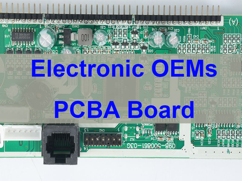
Electronic OEMs PCBA board manufacturing plays a critical role in modern electronics, enabling reliable circuit integration for industries such as power electronics, communication systems, automotive technology, and industrial automation. This article explains how OEM PCBA manufacturing works, what services are included, and how to choose a reliable electronic OEM PCBA board manufacturer for high-reliability products.
EBest Circuit (Best Technology) is a professional manufacturer specializing in electronic OEMs PCBA board fabrication and assembly with two decades of experience in electronics manufacturing. The company provides integrated services including PCB fabrication, global component sourcing, SMT assembly, and functional testing, supported by advanced production equipment and internationally recognized certifications such as ISO9001, ISO13485, IATF16949, and AS9100D. With strong engineering support, stable supply chain management, and full production traceability systems, EBest Circuit helps customers efficiently move from prototype development to stable mass production across industries such as power electronics, communication equipment, industrial automation, and automotive electronics. For reliable electronic oems pcba board manufacturing and assembly solutions, please contact us at sales@bestpcbs.com to discuss your project requirements.
Why Leading Companies Choose EBest for Electronic OEMs PCBA Board Fabrication?
Electronic OEMs PCBA board fabrication requires more than simple assembly capability. Reliable manufacturing depends on stable processes, certified quality systems, efficient supply chains, and engineering support that ensures every design can move smoothly from prototype to production.
Many electronic OEMs PCBA board companies offer assembly services, but few provide a fully integrated solution that combines PCB fabrication, component sourcing, PCBA assembly, and testing under one coordinated workflow. EBest focuses on delivering consistent manufacturing performance while supporting complex electronic products across multiple industries.
Electronic OEMs PCBA Board Companies vs Professional Manufacturing Partners
Many suppliers focus only on assembly, leaving customers to coordinate PCB suppliers and component distributors themselves. This fragmented approach often introduces delays and quality risks.
A professional manufacturer provides integrated services that reduce communication gaps and streamline production cycles.
Capability
Basic PCBA Suppliers
Professional OEM PCBA Manufacturer
PCB fabrication
External vendor
Integrated manufacturing
Component sourcing
Customer managed
Global supply chain support
Engineering review
Limited
DFM and process optimization
Traceability
Partial
Full MES tracking
Testing capability
Basic functional testing
AOI, X-ray, ICT and reliability tests
Electronic OEMs PCBA Board — Why Choose EBest
Stable Quality Systems – Certified manufacturing with ISO9001, ISO13485, IATF16949 and AS9100 standards.
Fast Turnaround – Rapid prototype production and reliable batch manufacturing.
Integrated Supply Chain – Global component sourcing combined with PCB fabrication and assembly.
Engineering Support – DFM analysis and process optimization before production begins.
Full Traceability – MES systems ensure every board can be tracked throughout manufacturing.
What Is an Electronic OEMs PCBA Board and How Does OEM Manufacturing Work?
An electronic OEMs PCBA board refers to a printed circuit board assembly manufactured by a specialized supplier for use in another company’s electronic product. The OEM provides design specifications while the manufacturer handles fabrication, assembly, and testing.
This model allows product companies to focus on design, software development, and product innovation while experienced manufacturing partners handle the production process.
Difference Between OEM and ODM PCBA
Aspect
OEM Manufacturing
ODM Manufacturing
Design ownership
Customer owns design
Manufacturer provides design
Customization level
Fully customized
Moderate customization
Product control
Client controlled
Shared development
Typical usage
Advanced electronics products
Standard product platforms
Typical OEM PCBA Manufacturing Workflow
Design file review and DFM analysis
PCB fabrication
Component procurement
SMT and through-hole assembly
Testing and inspection
Functional validation
Final packaging and shipment
What Services Are Included in Electronic OEMs PCBA Board Assembly?
A complete electronic OEMs PCBA board assembly service integrates multiple manufacturing stages to ensure reliability and efficiency. This approach simplifies production management and reduces coordination risks.
PCB Fabrication
PCB fabrication forms the foundation of every electronic assembly. Manufacturing accuracy determines electrical performance, mechanical stability, and long-term reliability.
Key fabrication capabilities include:
Multilayer PCB production
Impedance controlled stackups
High-current copper structures
High-frequency PCB materials
Surface finishes such as ENIG and ENEPIG
Component Sourcing
Reliable PCBA manufacturing depends heavily on component supply stability. Global sourcing networks ensure that components are available and traceable.
Authorized distributor sourcing
Component traceability management
BOM optimization
Supply chain risk mitigation
SMT Assembly
Surface mount technology is the core of modern electronics manufacturing. Automated assembly lines ensure consistent placement accuracy and production efficiency.
High-speed pick and place systems
Reflow soldering
Selective soldering
Automated optical inspection
Testing and Validation
Comprehensive testing ensures every electronic OEMs PCBA board meets performance expectations before shipment.
AOI inspection
X-ray analysis for BGA components
In-circuit testing
Functional verification
What Certifications Ensure Reliable Electronic OEMs PCBA Board Manufacturing?
Quality certifications ensure that PCBA manufacturing processes follow internationally recognized standards. These certifications demonstrate the manufacturer’s ability to produce high-reliability electronics.
ISO9001 Quality Management
This certification confirms that manufacturing processes follow strict quality management procedures and continuous improvement principles.
ISO13485 Medical Electronics Certification
Medical electronics require strict reliability and traceability. ISO13485 ensures controlled manufacturing processes suitable for healthcare devices.
IATF16949 Automotive Electronics Certification
Automotive electronics must operate reliably in demanding environments. This certification focuses on defect prevention and continuous quality improvement.
AS9100 Aerospace Certification
Aerospace electronics require extreme reliability and traceability. AS9100 ensures strict documentation and quality control across production processes.
What Challenges Do Companies Face When Sourcing Electronic OEMs PCBA Boards?
Electronic product development often encounters manufacturing challenges when transitioning from design to production. These issues can affect reliability, delivery stability, and product quality.
Design Manufacturability Challenges
PCB layouts that lack manufacturing optimization can lead to soldering defects or yield issues.
Supply Chain Instability
Electronic components may face availability fluctuations. Poor sourcing strategies can delay production.
Quality Inconsistency
Manufacturing variations across suppliers can lead to performance instability.
Communication Barriers
Working with multiple vendors increases coordination complexity and slows project execution.
How Does EBest Solve Electronic OEMs PCBA Board Manufacturing Challenges?
EBest addresses these challenges through an integrated engineering and manufacturing model that focuses on reliability and production stability.
Design for Manufacturing Analysis
Engineering teams perform detailed DFM analysis before production begins. This step ensures PCB layouts are optimized for manufacturing processes.
MES Traceability System
Every board produced within the factory is recorded within a manufacturing execution system. This allows complete production traceability.
Stable Supply Chain Network
Global component sourcing partners ensure stable supply while maintaining traceability for electronic components.
Efficient Production Workflow
Automated production lines combined with optimized scheduling support consistent manufacturing performance.
What Industries Use Electronic OEMs PCBA Boards?
Electronic OEMs PCBA boards are widely used across multiple technology sectors. These industries rely on reliable electronic assemblies to ensure product performance and durability.
Power Electronics and UPS Inverter Systems
Power conversion systems such as UPS equipment require high-current PCB designs and thermal management solutions.
Communication Equipment
Networking devices and communication infrastructure rely on high-density PCBA boards capable of handling high-speed signals.
Automotive Electronics
Modern vehicles integrate numerous electronic systems including driver assistance modules, infotainment units, and control systems.
Industrial Automation
Industrial equipment relies on robust electronic assemblies that operate reliably in demanding environments.
How Are China OEM UPS PCBA Inverter Electronic Circuit Board Assembly Services Built?
China OEM UPS PCBA inverter electronic circuit board assembly services focus on supporting power electronics products. These applications require specialized PCB designs capable of handling high current loads and thermal stresses.
High Current PCB Structures
Power inverter boards often use thick copper layers and reinforced traces to handle high current flows.
Thermal Management Design
Efficient heat dissipation ensures stable operation under continuous power loads.
Power Module Integration
Advanced PCBA designs integrate power components, control circuitry, and protection mechanisms.
Electronics Circuit Board PCBA PCB Custom OEM ODM — What Is the Difference?
Custom manufacturing models vary depending on design ownership and product development responsibility.
Feature
Custom OEM
ODM Manufacturing
Product design
Customer design
Manufacturer design
Customization flexibility
Full customization
Moderate customization
Development control
Customer controlled
Manufacturer led
How to Choose a Reliable Electronic OEMs PCBA Board Manufacturer?
Selecting the right manufacturing partner ensures stable product quality and reliable production cycles.
Engineering Capability
Experienced engineering teams can analyze PCB designs and optimize them for manufacturing efficiency.
Manufacturing Capacity
Production facilities must support both prototype development and volume manufacturing.
Traceability Systems
Modern factories implement MES systems that track every stage of manufacturing.
International Certifications
Quality certifications ensure compliance with industry requirements and manufacturing standards.
An electronic OEMsPCBA board is a fully assembled printed circuit board manufactured for use in another company’s electronic product. The design is provided by the product developer while manufacturing is performed by a specialized PCBA supplier.
What is the difference between PCB and PCBA?
A PCB refers to the bare printed circuit board without electronic components. A PCBA refers to the assembled board where components have been soldered onto the PCB.
How long does OEM PCBA manufacturing take?
Production time depends on design complexity, material availability, and testing requirements. Efficient manufacturing systems allow rapid prototype and batch production.
What industries require OEM PCBA boards?
Electronic OEM PCBA boards are widely used in communication equipment, industrial control systems, power electronics, automotive electronics, and consumer devices.
What testing methods ensure PCBA reliability?
Common testing methods include automated optical inspection, X-ray analysis, in-circuit testing, and functional verification.
Can OEM PCBA support prototypes and production?
Yes. Professional PCBA manufacturers support both prototype validation and volume production while maintaining consistent manufacturing processes.
Electronic schematics rely on standardized symbols to represent components. Among them, the capacitor symbol is one of the most frequently used in circuit diagrams. Whether you are designing a PCB, troubleshooting electronics, or studying circuit theory, understanding capacitor symbols is essential.
A capacitor symbol may look simple, but it carries useful information about the component type, polarity, and function in the circuit. Engineers use different capacitor symbols to represent ceramic capacitors, electrolytic capacitors, variable capacitors, and other types.
This guide explains the capacitor symbol meaning, explores different symbol types, and shows how to interpret them correctly in schematic diagrams.
Capacitor Symbol: Meaning, Types, and How to Read It in Circuit Diagrams
What Is a Capacitor Symbol in Electronics?
A capacitor symbol is a graphic used in circuit schematics to show the presence of a capacitor. Instead of drawing the actual part, engineers use a standard symbol to represent the capacitor’s electrical behavior.
A capacitor is an electronic component that stores and releases electrical energy in an electric field. It is built with two conductive plates separated by an insulating material called a dielectric.
In circuit diagrams, the capacitor symbol usually appears as two parallel lines that represent the two conductive plates.
The main functions of capacitors include:
Energy storage
Noise filtering in power supplies
Signal coupling and decoupling
Timing control in RC circuits
Voltage stabilization
Because capacitors are used in power, analog, digital, and RF designs, the capacitor symbol is one of the most important schematic symbols to understand.
What Does the Capacitor Symbol Mean in a Circuit Diagram?
The capacitor symbol meaning is not limited to showing that a capacitor is present. It also helps indicate how the part behaves in the circuit and, in some cases, what kind of capacitor it is.
In a schematic, the capacitor symbol often suggests:
The component can store electrical charge.
It may filter ripple, spikes, or signal noise.
It can block DC while allowing AC to pass.
It may work with a resistor to create a timing function.
Engineers read the capacitor symbol together with nearby components. For example, in a power supply, a capacitor often handles smoothing or decoupling. In an audio or analog path, it may be used for coupling. In RF circuits, it may support matching or filtering.
What Does the Standard Capacitor Symbol Look Like?
The standard capacitor symbol is simple and easy to recognize. It is usually drawn as two parallel plates separated by a small gap.
It may also appear in a horizontal connection style:
This standard symbol usually means:
Two identical conductive plates
No polarity requirement
Use for non-polarized capacitors
Typical parts shown with this symbol include:
Ceramic capacitors
Film capacitors
Mica capacitors
Other non-polarized capacitors
Because these parts can be installed in either direction, the symbol is symmetrical.
Why Are There Different Capacitor Symbols?
Different capacitor symbols exist because capacitors are not all the same. Some are non-polarized. Some are polarized. Some are adjustable. The symbol helps the designer, assembler, and technician identify the right type quickly.
A standard non-polarized capacitor can be connected in either direction. A polarized capacitor must be connected with the correct positive and negative terminals. A variable capacitor allows the capacitance value to be adjusted.
Common symbol differences are shown below:
Capacitor Type
Symbol Feature
Typical Use
Ceramic Capacitor
Two straight plates
High-frequency filtering and decoupling
Electrolytic Capacitor
Polarity marking or curved plate
Power supply smoothing
Variable Capacitor
Arrow across the plates
Tuning and calibration circuits
Polarized Capacitor
Positive or negative indication
DC circuits and bulk capacitance
What Is the Polarized Capacitor Symbol?
A polarized capacitor symbol shows that the capacitor must be connected in the correct direction. This is common for electrolytic capacitors and tantalum capacitors.
The symbol often includes one straight plate, one curved plate, and a polarity mark near the positive terminal.
In many schematics:
The straight plate is associated with the positive side.
The curved plate is associated with the negative side.
Polarized capacitors are often used in:
Power supply filtering
Bulk energy storage
Amplifier circuits
Voltage regulation sections
This is why the keyword capacitor symbol positive negative matters so much in practical circuit work. Correct polarity prevents installation mistakes and improves reliability.
What Is the Variable Capacitor Symbol?
A variable capacitor symbol represents a capacitor whose capacitance can be adjusted. It usually looks like a normal capacitor symbol with an arrow crossing it.
The arrow indicates that the capacitance value can change.
Variable capacitors are commonly used in:
RF tuning circuits
Radio receivers
Oscillators
Matching networks
In practical designs, the variable capacitor symbol tells the reader that tuning or calibration is part of the circuit function.
What Is the Difference Between IEC and ANSI Capacitor Symbols?
The two most common symbol standards are IEC and ANSI. Both are widely recognized, but there can be small visual differences depending on the documentation source.
Standard
Full Name
Common Use Region
IEC
International Electrotechnical Commission
Europe and many international documents
ANSI
American National Standards Institute
United States
In many cases, IEC uses clean, simple parallel-plate symbols, while ANSI drawings may show more style variation for polarized parts. Modern EDA software often supports both, so engineers should be familiar with each style.
How Do You Read a Capacitor Symbol in a Schematic?
Reading a capacitor symbol in a schematic involves more than identifying the drawing. You also need to read the reference designator, capacitance value, polarity, and circuit position.
Here is what to look for:
Reference designator: Capacitors are usually labeled with the letter C, such as C1, C12, or C205.
Capacitance value: Common values include 10uF, 100nF, and 1pF.
Polarity marking: Look for a plus sign, curved plate, or other polarity notation.
Placement in the circuit: A capacitor across power rails usually works as a decoupling capacitor. A capacitor in series with a signal path often works as a coupling capacitor.
Type clues: A symmetrical symbol often suggests a ceramic capacitor symbol or other non-polarized part. An arrow suggests a variable type.
When all of these details are read together, the circuit function becomes much clearer.
What Are the Most Common Capacitor Symbols Used in Electronics?
Several capacitor symbols appear regularly in electronic schematics. Each one represents a specific capacitor family or function.
Non-Polarized Capacitor Symbol
This is the most common form. It is widely used for ceramic, film, and general-purpose capacitors.
Ceramic Capacitor Symbol
The ceramic capacitor symbol usually uses the same basic two-plate form as the standard non-polarized symbol. It is common in decoupling, bypass, and high-frequency designs.
Polarized Capacitor Symbol
The polarized capacitor symbol is used for electrolytic and tantalum capacitors where direction matters.
Variable Capacitor Symbol
The variable capacitor symbol includes an arrow and is common in tunable analog and RF circuits.
Trimmer Capacitor Symbol
This symbol is similar to a variable capacitor but is generally used for calibration rather than frequent adjustment.
Capacitor Symbol vs Resistor Symbol: What Is the Difference?
The capacitor symbol and resistor symbol are both basic schematic elements, but they represent very different electrical functions.
Component
Common Symbol Style
Main Function
Capacitor
Two parallel plates
Stores electrical energy
Resistor
Zigzag line or rectangle
Limits current flow
A capacitor affects voltage and time behavior. A resistor controls current and voltage drop. When used together, they form common building blocks such as RC filters, delay networks, and timing circuits.
Conclusion
The capacitor symbol is a small mark with a big role in electronics. It helps engineers identify capacitor types, understand polarity, and interpret circuit function quickly.
Once you understand the difference between the standard capacitor symbol, the ceramic capacitor symbol, the polarized capacitor symbol, and the variable capacitor symbol, reading schematics becomes much easier.
Whether you are working on circuit design, PCB layout design, electronics repair, or engineering education, understanding capacitor symbols is a basic but valuable skill.
EBest Circuit (Best Technology) provides professional PCB fabrication and PCBA assembly services for engineers who need reliable support from prototype to production.
Contract manufacturing electronic assembly is a strategic manufacturing model that helps OEMs turn PCB designs into finished, tested, and scalable electronic products with better speed, process control, and supply chain coordination. This article explains the engineering workflow, thermal calculations, sourcing integration, capability evaluation, production scaling, design support, electro-mechanical assembly, quality control, and global market landscape behind expedited electronic assembly services.
Common Customer Pain Points Often Look Like This:
DFM issues are found too late and delay launch.
PCB fabrication, sourcing, and assembly are split across too many vendors.
Thermal and current limits are not verified early enough.
Prototype success does not transfer smoothly into volume production.
Supplier communication is slow when urgent changes happen.
How A Manufacturer Responds To Those Pain Points:
Review Gerber, BOM, and assembly risks before release.
Combine PCB fabrication, sourcing, and PCBA under one workflow.
Validate thermal paths and current carrying capacity during engineering review.
Build processes that support both low-volume and mass production.
Use responsive project management for expedited service execution.
EBest Circuit (Best Technology) is a professional PCB and PCBA manufacturer focused on prototype, low-volume, and medium-batch electronic products that require fast turnaround and dependable engineering support. We provide PCB fabrication, component sourcing, SMT, DIP, testing, and box-build integration with a practical engineering mindset, helping customers shorten development cycles while improving manufacturability and delivery reliability. For project support, pls feel free to contact us via sales@bestpcbs.com.
What Engineering Processes Are Included In Contract Manufacturing Electronic Assembly From DFM To Final Testing?
A strong contract manufacturing electronic assembly process is not just about placing parts on a PCB. It is a controlled engineering chain that starts with design review and ends with validated product output. For expedited service, each step must be linked clearly to the next.
Typical Engineering Flow
Stage
Main Task
Core Output
DFM Review
Check manufacturability risk
DFM comments
BOM Review
Verify parts, alternates, lifecycle
BOM optimization
PCB Fabrication Prep
Confirm stack-up, finish, panelization
Fabrication release
SMT/DIP Process Setup
Define stencil, fixture, profile
Process package
Assembly Execution
Mount, solder, inspect
Assembled PCBA
Testing
AOI, X-Ray, ICT, FCT
Test records
Final Inspection
Verify workmanship and labeling
Shipment approval
Key Engineering Elements
DFM Review: pad design, spacing, via structure, solder mask clearance, fiducials, panel strategy.
In practical terms, electronics assembly contract manufacturing works best when engineering, purchasing, production, and QA are aligned from day one. That alignment is what turns a rush order into a controlled build rather than a reactive one.
How To Calculate Thermal Dissipation And Current Carrying Capacity In Contract Manufacturing Electronic Assembly Designs?
For expedited builds, thermal and electrical validation cannot be treated as a late-stage check. In contract manufacturing electronic assembly projects, overheating, trace overload, and poor heat spreading can quickly undermine reliability even if assembly quality looks fine.
1) Thermal Resistance Calculation
A simple thermal model begins with:
Where:
(R_{\theta}) = thermal resistance (°C/W)
(T_j) = junction temperature
(T_a) = ambient temperature
(P) = power dissipation (W)
Example: If a device has a junction limit of 125°C, ambient is 45°C, and power is 4 W:
That means the full thermal path from junction to air must stay at or below 20°C/W.
2) PCB Trace Current Carrying Capacity
A widely used engineering expression based on IPC practice is:
Where:
(I) = allowable current
(\Delta T) = temperature rise
(A) = conductor cross-sectional area
(k) = layer constant
Quick Design Factors
Factor
Higher Value Effect
Engineering Impact
Copper Thickness
Increases current capacity
Better for power lines
Trace Width
Lowers resistance
Reduces temperature rise
Copper Plane Area
Improves heat spread
Better thermal stability
Thermal Vias
Moves heat vertically
Helps hot components
Airflow
Improves cooling
Lowers junction temp
What Engineers Should Check
Power components near thermal bottlenecks
Copper thickness on high-current nets
Internal vs external trace conditions
Via-in-pad or thermal via arrays under power packages
Safe margin between actual and allowable temperature rise
An experienced electronic assembly contract manufacturer does not only assemble what is drawn. It also flags thermal imbalance, copper weakness, and layout risks before they become field failures. That is especially important in power supplies, motor control boards, LED drivers, telecom modules, and industrial control systems.
In short, thermal dissipation and current capacity calculations help convert a fast build into a reliable one. Speed without thermal validation is fragile. Speed with engineering discipline is scalable.
How Do Electronic Assembly Contract Manufacturers Handle PCB Fabrication, Component Sourcing, And PCBA Integration?
Customers often struggle when PCB fabrication, procurement, and assembly are managed by separate vendors. A mature electronic assembly contract manufacturer reduces that friction by integrating the full chain into one coordinated workflow.
Logistics Coordination: incoming material control, line kitting, build scheduling, traceable shipment release.
What Good Integration Looks Like
Area
Poor Coordination Result
Integrated Result
PCB + BOM Timing
Idle assembly line
Synchronized material arrival
Shortage Handling
Last-minute delay
Approved alternates ready
Engineering Change
Document mismatch
Controlled ECO execution
Build Planning
Mixed priorities
Clear production scheduling
Practical Benefits
Fewer handoff errors.
Faster feedback between sourcing and engineering.
Shorter turnaround for prototypes.
Better traceability from bare board to final assembly.
Easier root-cause analysis when issues appear.
This is where electronic assembly contract manufacturing becomes more than a purchasing model. It becomes an execution model. For expedited service, that execution discipline is often the difference between an on-time build and a delayed launch.
What Manufacturing Capabilities Should You Evaluate In Electronic Assembly Contract Manufacturing Partners?
Not all partners that offer electronic assembly contract manufacturing have the same engineering depth or production fit. A useful evaluation should go beyond brochure language and focus on capability that affects yield, lead time, and product consistency.
Production Flexibility: prototype, NPI, low-volume, repeat batch, mass production.
Traceability System: lot control, barcode tracking, process records, test history.
Engineering Support: DFM, DFA, BOM review, alternate recommendation, process optimization.
Fast Screening Table
Capability
Why It Matters
Fine-Pitch SMT
Supports dense modern designs
BGA/X-Ray
Controls hidden solder joints
Prototype + Volume
Enables growth path
Material Sourcing Team
Reduces shortage risk
Test Engineering
Improves outgoing reliability
Process Traceability
Supports regulated industries
Questions Worth Asking
Can the supplier support both quick-turn NPI and stable repeat production?
Can it manage difficult packages and mixed assembly processes?
Does it provide engineering feedback before production starts?
How does it respond to shortages and urgent ECOs?
What evidence does it provide for quality control?
A reliable partner in electronics assembly contract manufacturing should make your product easier to launch, easier to scale, and easier to control. If it only offers placement capacity without engineering support, the risk remains with the customer.
How Does Electronics Contract Manufacturing Assembly Support Low Volume Prototyping And Mass Production?
One of the biggest challenges in electronics contract manufacturing assembly is moving smoothly from prototype to scale. A rushed prototype may prove function, but it does not automatically prove manufacturability. Good contract assembly service bridges both stages with process continuity.
Low-Volume Prototype Priorities
Fast engineering review
Manual or semi-automated flexibility
Rapid material substitution handling
Frequent revision support
Quick debug feedback
Mass Production Priorities
Stable approved BOM
Standardized work instructions
Line balancing and fixture planning
Yield monitoring
Controlled logistics and replenishment
Comparison Table
Build Type
Main Goal
Typical Focus
Prototype
Verify design
Speed and flexibility
Pilot Run
Validate process
Repeatability
Mass Production
Deliver volume
Stability and cost control
How A Good Manufacturer Supports Both
Keeps the same engineering data structure from NPI to production.
Records process settings that can be reused later.
Captures defects early and feeds them back to design.
Builds scalable sourcing plans around real demand.
Aligns inspection depth with product risk and stage.
This is why contract manufacturing electronics assembly is valuable for OEMs that expect growth. It is not just about assembling today’s boards. It is about building a repeatable path from first article to mature production.
What Engineering Services Are Provided In Contract Design And Manufacturing Electronic Assembly Projects?
In contract design and manufacturing electronic assembly projects, the supplier may contribute far more than assembly labor. The right engineering service can reduce redesign cycles, improve reliability, and speed up qualification.
Common Engineering Services
DFM and DFA review
BOM optimization
Alternate component evaluation
PCB stack-up suggestion
Thermal and current path review
Panelization support
Test point planning
Fixture and stencil design
Process profile development
Service Breakdown
Service
Value To Customer
DFM Review
Prevents fabrication and assembly defects
BOM Optimization
Improves availability and cost stability
Thermal Review
Reduces overheating risk
Test Planning
Makes debugging and validation easier
Process Setup
Improves yield on first build
Where This Helps Most
New product introduction
Mixed-technology boards
Dense PCBs with thermal load
Long-lead or shortage-prone BOMs
Products needing fast release
A supplier that supports contract design and manufacturing electronic assembly well is acting as an engineering extension of the customer, not just a production stop. For expedited service, that shared engineering effort saves time where it matters most: before material is committed and before defects multiply.
What Is Electro-Mechanical Assembly For Electronics Contract Manufacturing And Where Is It Used?
Electro-mechanical assembly for electronics contract manufacturing refers to the integration of electronic assemblies with mechanical elements such as enclosures, harnesses, connectors, switches, fans, brackets, displays, and power modules. It takes the product from board level toward system level.
Typical Scope
PCB + enclosure integration
Cable and wire harness assembly
Connector installation
Mechanical fastening
Display and HMI integration
Fan, sensor, and power module mounting
Final box-build and system test
Common Applications
Industrial control units
Medical devices
Telecom equipment
EV charging modules
Security systems
Consumer electronics
Embedded control products
Typical System-Level Benefits
Fewer assembly handoffs.
Better fit between PCB and housing.
Lower shipping and handling damage risk.
Simpler final product logistics.
More complete outgoing testing.
When OEMs need more than bare PCBA, this service becomes highly practical. It is especially useful when cable routing, connector access, thermal layout, or final mechanical packaging affects field performance.
How Does Contract Manufacturing Electronics Assembly Ensure Quality And Supply Chain Stability?
For expedited orders, quality and supply chain stability must move together. A fast build with weak sourcing control creates shortage risk. A well-sourced build with weak process control creates field risk. Strong contract manufacturing electronics assembly addresses both.
Quality Control Structure
Incoming material inspection
SPI for solder paste consistency
AOI after SMT
X-Ray for BGA and hidden joints
ICT or flying probe for electrical checks
Functional test for product behavior
Final visual and packaging inspection
Supply Chain Stability Methods
Approved vendor lists
Alternate part strategy
Lifecycle monitoring
Safety stock for repeat projects
Lot traceability
Shortage escalation process
Condensed Control Table
Control Area
Stabilizing Method
Material Quality
Incoming IQC
Solder Process
SPI + profile control
Hidden Joints
X-Ray inspection
Functional Confidence
ICT/FCT
Part Shortages
AVL + alternates
Traceability
Barcode and batch records
What Customers Should Expect
Transparent shortage communication.
Evidence-based quality records.
Controlled handling of substitutions.
Repeatable build documentation.
Fast response when corrective action is needed.
This is where electronics assembly contract manufacturing shows its real value. It protects both the schedule and the shipment quality. In expedited service work, those two goals must be managed together, not separately.
Who Are The Largest Electronic Contract Manufacturers For PC Board Assembly In The Global Market?
The largest electronic contract manufacturers for pc board assembly usually operate at massive global scale, serving consumer electronics, automotive, telecom, industrial, and computing markets. They are important benchmarks, but they are not always the best fit for every OEM.
Large Global EMS Players Are Known For
Very high production capacity
Broad regional manufacturing footprint
Mature supply chain influence
System-level integration capability
Strong process standardization
But Size Is Not The Only Buying Criterion
Large Global EMS
Agile Mid-Sized Specialist
Best for huge volume
Best for responsive support
Strong purchasing power
Faster engineering feedback
More layered communication
More direct project contact
High process maturity
Better fit for NPI and mixed batch
What Many OEMs Actually Need
Faster response than a mega-EMS can offer
Better support for prototypes and low-volume orders
Stronger engineering discussion during DFM and BOM review
Easier customization for mixed products
A more practical expedited service path
For many PCB-centered projects, the ideal partner is not necessarily the biggest. It is the supplier with the right mix of engineering support, assembly control, sourcing agility, and communication speed.
Ultimately, contract manufacturing electronic assembly is a high-value manufacturing approach that helps OEMs transform PCB designs into reliable products through coordinated engineering review, sourcing control, assembly execution, testing, and scalable production support. This article covered the core workflow from DFM to final testing, thermal and current calculations, integration of PCB fabrication and sourcing, partner evaluation, prototype-to-volume transition, design support, electro-mechanical assembly, quality assurance, and the global EMS landscape.
EBest Circuit (Best Technology) combines PCB fabrication, component sourcing, PCBA assembly, testing, and responsive engineering service to support expedited electronic manufacturing projects with stronger control and better communication. For RF boards, industrial controls, power electronics, medical devices, and other demanding applications, we help customers move faster with practical manufacturing support and dependable execution. If you have any electronics assembly contract manufacturing needs, pls feel free to contact us at sales@bestpcbs.com.
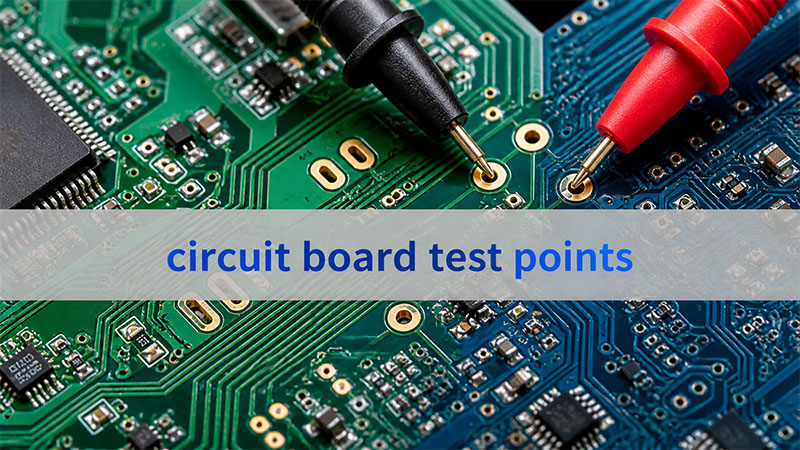
FAQs About Contract Manufacturing Electronic Assembly
What PCB Thickness Is Typically Used In Contract Manufacturing Electronic Assembly Projects? Most PCB assemblies use board thickness between 1.0 mm and 1.6 mm, with 1.6 mm being the most common standard for industrial electronics. However, compact devices such as IoT modules may use 0.8 mm or thinner boards, while high-power or connector-heavy designs may require 2.0 mm–3.2 mm thickness to improve mechanical rigidity and thermal performance. PCB thickness must also match connector specifications, enclosure tolerance, and impedance requirements.
What Copper Thickness Is Recommended For High-Current PCB Assemblies? Copper thickness determines how much current a trace can safely carry. In most electronics assembly contract manufacturing projects, standard copper weight is 1 oz (35 μm). For power electronics or motor control boards, engineers may choose 2 oz (70 μm) or 3 oz (105 μm) copper. Heavy-copper PCBs above 4 oz are sometimes used in power converters, LED drivers, and industrial equipment where current paths exceed 10–20 A.
What Is The Typical Reflow Soldering Temperature Profile For SMT Assembly? In electronic assembly contract manufacturing, the SMT reflow profile depends on the solder alloy used. For common lead-free SAC305 solder, the typical parameters are:
Stage
Typical Temperature
Duration
Preheat
150–180°C
60–120 s
Soak
180–200°C
60–90 s
Reflow Peak
235–250°C
20–40 s
Cooling
−3°C/sec typical
Controlled
The peak temperature must remain below most component limits, which are usually 260°C maximum.
What Is The Typical Placement Accuracy In Modern SMT Assembly Lines? Modern SMT production equipment used in electronics contract manufacturing assembly can achieve placement accuracy between ±30 μm and ±50 μm depending on machine class and component size. High-precision machines used for fine-pitch QFN, CSP, and 0201 components may achieve ±25 μm accuracy. Accurate placement is critical for preventing solder bridging, improving yield, and ensuring consistent assembly quality in high-density PCB designs.
Solder is the invisible backbone of modern electronics. Every smartphone, industrial controller, and medical device depends on thousands of tiny solder joints to create electrical connections. For decades, engineers relied on traditional tin-lead solder. Today, however, most electronics manufacturing uses lead-free alloys.
This shift created an ongoing discussion among engineers and manufacturers: leaded vs lead free solder — which one actually performs better in PCB assembly?
What Is the Difference Between Leaded vs Lead Free Solder?
The main difference between leaded vs lead free solder lies in the alloy composition. Leaded solder contains lead, while lead-free solder replaces it with other metals such as silver or copper.
Traditional solder used in electronics for decades is a tin-lead alloy, often written as Sn63/Pb37. Lead-free solder removes lead due to environmental regulations. Below is a simple comparison:
Property
Leaded Solder
Lead Free Solder
Typical Alloy
Sn63/Pb37
SAC305 (Sn96.5/Ag3/Cu0.5)
Melting Temperature
~183°C
~217-221°C
Wettability
Excellent
Moderate
Mechanical Strength
Good
Higher strength but more brittle
Environmental Impact
Contains toxic lead
Environmentally safer
Industry Compliance
Not RoHS compliant
RoHS compliant
Leaded solder forms smooth and shiny joints. It flows easily during reflow. Many engineers still appreciate its process stability.
Lead-free solder focuses on environmental safety. It reduces heavy metal contamination and supports global electronics regulations.
Today, most commercial electronics rely on lead-free alloys, though leaded solder remains common in specialized sectors.
Why Did the Electronics Industry Move from Leaded to Lead Free Solder?
The transition from leaded to lead-free solder was driven mainly by environmental regulations.
Lead is a heavy metal. If discarded electronics enter landfills, lead may contaminate soil and water. Governments began addressing this concern in the early 2000s.
One of the most important regulations is the RoHS directive (Restriction of Hazardous Substances) introduced in the European Union.
RoHS restricts several materials in electronics, including:
Lead (Pb)
Mercury (Hg)
Cadmium (Cd)
Hexavalent chromium
Certain flame retardants
Under RoHS rules, most consumer electronics must avoid lead. Because of this regulation, global manufacturers shifted their production processes. Lead-free solder became the industry standard.
The move required major adjustments:
Higher reflow temperatures
New solder alloys
Improved PCB materials
More precise process control
Modern PCBA factories now design equipment and processes around lead-free assembly.
Is Leaded Solder Better Than Lead Free Solder?
The answer depends on the application. In terms of process behavior, many engineers find leaded solder easier to use. It melts at lower temperature and wets copper pads quickly.
However, lead-free solder offers strong environmental benefits and better long-term compliance.
Factor
Leaded Solder
Lead Free Solder
Process stability
Very stable
Requires tighter process control
Reflow temperature
Lower
Higher
Environmental safety
Lower
Higher
Compliance
Limited
Global standard
Mechanical strength
Flexible
Strong but harder
Leaded solder is still preferred in some specialized industries such as:
aerospace electronics
military equipment
high-reliability legacy systems
Lead-free solder dominates consumer electronics, automotive electronics, and industrial equipment. Most new electronic products today are designed around lead-free assembly processes.
What Is the Melting Point of Leaded vs Lead Free Solder?
Melting temperature is one of the most critical differences between leaded vs lead free solder.
The widely used Sn63/Pb37 alloy melts at 183°C. It has a eutectic composition. This means it transitions directly from solid to liquid without a plastic phase.
Lead-free alloys melt at higher temperatures, common lead-free alloys include:
Alloy
Composition
Melting Range
SAC305
Sn96.5 Ag3 Cu0.5
217-221°C
SAC405
Sn95.5 Ag4 Cu0.5
~217-219°C
SnCu
Tin-Copper
~227°C
Because of the higher melting point, lead-free solder requires:
higher reflow oven temperatures
more heat-resistant components
PCB laminates with higher Tg
Typical peak reflow temperatures for lead-free solder reach 240-250°C.
Why Is Lead Free Solder Harder to Work With?
Many engineers report that lead-free solder is more difficult to work with compared to leaded solder. There are several reasons for this:
1. Higher melting temperature
Lead-free alloys require higher soldering temperatures, which can increase thermal stress on components and PCB materials.
2. Reduced wetting performance
Lead-free solder tends to spread less easily across metal surfaces, making it harder to form smooth solder joints.
3. Oxidation sensitivity
Lead-free alloys oxidize more quickly at high temperatures, which can affect solder joint quality.
4. Different joint appearance
Unlike the shiny joints produced by leaded solder, lead-free joints often appear dull or grainy, which can confuse technicians during inspection.
For these reasons, PCB manufacturers must carefully control:
Reflow temperature profiles
Flux chemistry
Surface finishes such as ENIG or OSP
Lead Free vs Lead Solder: Reliability Comparison
Reliability is a major factor when evaluating lead free vs lead solder. Leaded solder has long been known for its excellent fatigue resistance and mechanical flexibility. Lead-free solder, while environmentally friendly, can be more brittle due to its alloy structure.
Reliability Factor
Leaded Solder
Lead Free Solder
Thermal fatigue resistance
High
Moderate
Mechanical flexibility
Good
Lower
Operating temperature tolerance
Moderate
Higher
Long-term reliability
Proven
Improving
Despite these concerns, improvements in lead-free alloy formulations and process control have significantly improved reliability in recent years.
What Temperature Should Be Used for Lead Free Solder?
In PCB assembly, lead-free solder requires a carefully controlled reflow temperature profile. For the commonly used SAC305 alloy, the typical reflow profile includes:
Reflow Stage
Temperature Range
Purpose
Preheat
150–180°C
Gradually warm the PCB
Soak
180–200°C
Activate flux and equalize temperature
Reflow
Above 217°C
Melt solder and form joints
Peak
240–250°C
Ensure complete solder wetting
Cooling
Controlled drop
Solidify solder joints
Maintaining the correct temperature profile ensures strong, reliable solder joints without damaging components.
Can You Mix Leaded and Lead Free Solder?
Mixing leaded and lead-free solder is generally not recommended in production environments. When the two alloys mix, they form unpredictable metallurgical structures that can affect reliability and melting behavior.
Potential problems include:
Irregular melting temperatures
Weak solder joints
Poor wetting performance
In repair or rework situations, technicians may sometimes mix alloys, but it is best practice to fully remove the old solder before applying a different alloy type.
Typical processes that use lead-free solder include:
SMT reflow soldering
Wave soldering
Selective soldering
However, certain high-reliability electronics still prefer leaded solder due to its proven long-term reliability. Examples include:
aerospace avionics
defense electronics
specialized medical equipment
These applications often operate under strict reliability requirements, where long-term performance is critical.
How to Choose Between Leaded and Lead Free Solder?
Choosing between leaded vs lead free solder depends on several factors related to your product design, regulatory requirements, and reliability needs. Consider the following points:
Choose lead-free solder if:
Your product must comply with RoHS regulations
You manufacture consumer electronics
Environmental compliance is required
Choose leaded solder if:
Your product falls under RoHS exemptions
Maximum reliability is required
The system operates in harsh environments
Most modern PCB manufacturers support both soldering technologies, depending on customer requirements.
If you are developing a new electronics product or planning PCB assembly, working with an experienced manufacturing partner can make a significant difference.
EBest Circuit (Best Technology) provides complete PCB fabrication and PCBA services, supporting prototypes, small-volume production, and complex electronics projects.
For technical consultation or manufacturing inquiries, feel free to contact: sales@bestpcbs.com
FAQs
1. Is lead free solder better than leaded solder?
Lead-free solder is better for environmental compliance and regulatory requirements. However, leaded solder is often easier to work with and historically offers excellent reliability.
2. Why is lead free solder required?
Lead-free solder is required mainly because of environmental regulations such as RoHS, which restrict the use of hazardous substances like lead in electronic products.
3. What temperature melts lead free solder?
Most lead-free solder alloys melt between 217°C and 221°C, depending on the specific alloy composition.
4. Can lead free solder cause reliability issues?
Early lead-free solder alloys had reliability concerns, but modern alloys such as SAC305 have significantly improved performance and are widely used in commercial electronics.
5. Is lead free solder required for RoHS compliance?
Yes. Products that must comply with RoHS regulations generally require lead-free solder unless the product qualifies for a specific exemption.
Box build printed circuit board assembly services play a critical role in modern electronics manufacturing by integrating PCB fabrication, component assembly, mechanical enclosure installation, wiring harnesses, and system testing into a single streamlined production process. This article explains how box build PCBA works, what technologies and engineering parameters are involved, and how to choose a reliable manufacturing partner for complete electronic product integration.
EBest Circuit (Best Technology) is an experienced provider of box build printed circuit board assembly services, offering a one-stop solution that covers PCB fabrication, component sourcing, PCBA manufacturing, wiring harness assembly, and full product integration. With more than 20 years of industry mileage, and certifications including ISO9001, ISO13485, IATF16949, and AS9100D, EBest supports demanding projects from industries such as medical devices, industrial control, and aerospace. If you are looking for reliable box buildprinted circuit board assembly services to support your next electronics project, feel free to contact our engineering team at sales@bestpcbs.com for professional assistance and a fast quotation.
What Are Box Build Printed Circuit Board Assembly Services?
Box build printed circuit board assembly services refer to a complete manufacturing process that integrates PCB fabrication, component assembly, wiring, enclosure installation, and final product testing.
Unlike standard printed circuit board assembly services, which only assemble electronic components onto a PCB, box build services deliver a fully integrated electronic system.
Typical processes involved in box build manufacturing include the following stages.
Manufacturing Stage
Key Function
PCB Fabrication
Bare PCB manufacturing
Component Procurement
Authorized component sourcing
SMT Assembly
Automated surface-mount placement
Through-Hole Assembly
Power and connector soldering
Cable Harness Assembly
Wiring and cable integration
Mechanical Assembly
Mounting PCBA into enclosure
System Integration
Installing modules and subsystems
Functional Testing
Electrical and system verification
Final Packaging
Labeling and shipment preparation
This comprehensive workflow allows printed circuit board pcb assembly services to evolve from simple board assembly to complete electronic product integration.
What Processes Are Included in Printed Circuit Board Assembly Services?
At the core of box build printed circuit board assembly services lies professional PCBA manufacturing. Reliable circuit board assembly services typically include several key production technologies.
Surface Mount Technology (SMT)
SMT is the primary assembly method used in modern electronics manufacturing. In this process, miniature electronic components are mounted directly onto PCB pads using automated placement machines.
The typical SMT workflow includes:
Solder paste printing
High-speed component placement
Reflow soldering
Automated optical inspection (AOI)
Advanced SMT production lines can place more than 50,000 components per hour, ensuring high productivity and precision.
Typical SMT assembly capabilities are shown below.
Parameter
Typical Capability
Minimum component size
01005
BGA pitch
0.3 mm
Placement accuracy
±30 μm
Maximum PCB size
600 × 500 mm
Minimum PCB thickness
0.4 mm
These capabilities are commonly required in quick turn printed circuit board assembly services for prototypes and small batch production.
Through-Hole Technology (THT)
Although SMT dominates modern electronics manufacturing, many components still require through-hole mounting for mechanical strength or high current handling.
Examples include:
Power connectors
transformers
large electrolytic capacitors
mechanical switches
These components are soldered using:
wave soldering
selective soldering
manual soldering for complex assemblies
Combining SMT and THT ensures both electrical performance and mechanical reliability in printed circuit board assembly service operations.
PCBA Testing and Inspection
Testing is critical to ensure the quality and reliability of printed circuit board assembly services.
Common inspection and testing technologies include:
Test Method
Function
AOI
Detects solder bridges, polarity errors, and missing components
X-Ray Inspection
Verifies hidden solder joints such as BGA connections
ICT (In-Circuit Test)
Checks electrical continuity and component values
Flying Probe Test
Used for prototypes without test fixtures
Functional Test
Simulates real operating conditions
Advanced printed circuit board assembly services USA providers often integrate MES systems to maintain full production traceability.
What Technical Parameters Define High-Quality Box Build PCBA?
Beyond assembly processes, several engineering parameters determine the quality and reliability of box build printed circuit board assembly services.
PCB Current Carrying Capacity
The current capacity of a PCB trace depends on copper thickness, trace width, and temperature rise.
A simplified formula derived from IPC-2152 is:
Where:
Symbol
Meaning
I
Current capacity (Amps)
ΔT
Temperature rise
A
Cross-section area of copper
k
Constant depending on layer type
For example, a 1 oz copper trace with a width of 20 mil typically carries around 2–3 A depending on cooling conditions.
This parameter becomes particularly important in industrial control box build systems where power modules are integrated.
Signal Integrity and Impedance Control
High-speed digital signals require controlled impedance traces to avoid signal reflection and distortion.
Typical impedance targets include:
Interface Type
Typical Impedance
USB differential pair
90 Ω
Ethernet
100 Ω
RF signal lines
50 Ω
LVDS
100 Ω
A simplified microstrip impedance equation is:
Where:
(ε_r) is dielectric constant
(h) is dielectric thickness
(w) is trace width
(t) is copper thickness
Professional printed circuit board pcb assembly services verify impedance using TDR testing.
Thermal Resistance of Electronic Components
Thermal performance is another critical engineering parameter.
The junction temperature of a semiconductor can be estimated using:
Where:
Symbol
Meaning
Tj
Junction temperature
Ta
Ambient temperature
P
Power dissipation
RθJA
Thermal resistance
Example:
If a device dissipates 5W, with thermal resistance 20°C/W, and ambient temperature 40°C, then:
Such temperature levels require improved thermal management solutions.
How Does Box Build Assembly Work in Electronics Manufacturing?
While printed circuit board assembly services focus on electronic boards, box build integrates the entire product.
A typical workflow includes:
Step
Process
1
PCB fabrication
2
PCBA assembly
3
wiring harness preparation
4
enclosure installation
5
power module integration
6
system wiring
7
functional testing
8
final packaging
A typical box build structure may include the following subsystems.
Subsystem
Example Components
Control board
MCU PCBA
Power module
DC-DC converters
Interface board
Ethernet or USB modules
Mechanical enclosure
Aluminum chassis
Cooling system
Heat sink or fan
Wiring harness
Signal and power cables
This integrated approach allows assembly services for circuit boards to deliver complete electronic products.
Thermal Management Design in Box Build Electronics
Thermal management is a key engineering challenge in box build printed circuit board assembly services, particularly when electronics operate in enclosed environments.
Aluminum PCB for Heat Dissipation
Different PCB materials provide different thermal conductivity.
Material
Thermal Conductivity
FR-4
0.3 – 0.4 W/mK
Aluminum PCB
2 – 3 W/mK
Copper base PCB
5 – 8 W/mK
Aluminum PCBs are widely used in:
LED lighting systems
power electronics
automotive electronics
Heat Sink Design
Heat dissipation through convection can be estimated using:
Where:
Symbol
Meaning
Q
Heat transfer
h
Heat transfer coefficient
A
Surface area
Ts
Surface temperature
Ta
Ambient temperature
This formula helps engineers design efficient cooling structures for high-power electronic systems.
Forced Air Cooling
When power density exceeds 10 W per PCB, passive cooling may be insufficient.
In such cases, engineers may integrate:
cooling fans
ventilation openings
heat pipes
These solutions are common in industrial and telecom box build systems.
What Industries Need Box Build Printed Circuit Board Assembly Services?
Many industries rely on box build printed circuit board assembly services for complete product integration.
A supplier capable of providing quick turn circuit board assembly services USA or Asia-based rapid manufacturing can significantly shorten product development cycles.
Why Work With a Professional Box Build PCBA Manufacturer?
A professional partner offering box build printed circuit board assembly services should provide both manufacturing capability and engineering expertise.
For example, EBest Circuit (Best Technology) provides:
over 20 years of PCB and PCBA manufacturing experience
China electronic circuit board assembly plays a central role in turning electronic designs into manufacturable, testable, and scalable products for global OEMs. This article explains how a strong supply chain, sound engineering practice, and disciplined PCBA execution help buyers reduce risk, improve reliability, and move from prototype to production.
What usually makes sourcing and manufacturing difficult for customers?
Parts are available on paper, but actual lead times shift too often.
DFM issues are found too late, causing rework and delay.
PCB, sourcing, assembly, and testing are handled by different vendors.
Prototype builds go fast, but volume quality becomes unstable.
Traceability is weak, making root-cause analysis slow and costly.
A strong manufacturer solves these problems with a system, not with promises.
Review files early and issue DFM feedback before release.
Optimize BOM risk with alternative parts and sourcing strategy.
Integrate PCB fabrication, component sourcing, PCBA, and testing.
Build stable processes for both prototypes and repeat production.
Use digital traceability to track material lots, process status, and product history.
EBest Circuit (Best Technology) is a professional PCB and PCBA manufacturer focused on helping engineers and OEM teams bring products to market with less friction. With in-house PCB and PCBA factories, DFM pre-check, BOM optimization support, 20 years of manufacturing experience, and a digital workshop with fast traceability, EBest supports prototype, low-volume, and ongoing production projects with stronger execution. For project discussion or quotation, pls feel free to contact us via sales@bestpcbs.com.
Why Do Global Brands Choose A China Electronic Circuit Board Assembly Factory?
Global brands choose a China electronic circuit board assembly factory for one reason above all: the right supplier can combine engineering support, cost control, production scale, and supply chain depth in one place. In electronics, that combination matters more than low unit price alone.
A capable China factory is rarely just an assembly shop. The stronger ones operate as manufacturing partners. They support file review, material selection, procurement control, process planning, SMT and THT assembly, testing, and delivery management. This matters because most project failures happen between these steps, not inside one step.
Here are the main reasons global brands keep sourcing from China:
Dense component ecosystem China has a deep electronics supply base, which improves access to circuit board electronic components and reduces sourcing friction.
Integrated manufacturing flow PCB fabrication, stencil making, SMT, DIP, box build, and testing can be coordinated faster.
Better prototype-to-production transition The same team can often support NPI, pilot run, and repeat orders.
Engineering responsiveness Strong suppliers do not simply build to print. They flag layout, pad, thermal, and assembly risks early.
Cost-to-capability balance Buyers often get a better mix of technical support, lead time, and manufacturing value.
A quick comparison makes this clearer:
Factor
Strong China Supplier
Fragmented Multi-Vendor Model
PCB + PCBA coordination
Fast
Slow
BOM sourcing visibility
High
Low
Engineering feedback
Early
Delayed
Prototype response
Flexible
Often rigid
Supply chain leverage
Strong
Limited
For buyers, the real attraction is not geography by itself. It is operational concentration. When sourcing, engineering, and manufacturing are aligned, project risk drops. That is why a strong China electronic circuit board assembly factory remains a practical choice for global OEMs.
How To Choose A Reliable China Electronic Circuit Board Assembly Manufacturer For OEM Projects?
Choosing a reliable China electronic circuit board assembly manufacturer is a technical and commercial decision at the same time. A good website or a low quote is not enough. Buyers need evidence that the supplier can support the product, not just produce the board.
Start by checking whether the manufacturer understands your project type. Industrial control, medical electronics, UPS power boards, communication devices, and automotive electronics do not share the same process priorities. The supplier should know what matters for your application, whether that is thermal control, creepage distance, conformal coating, functional test, or long-life solder joint reliability.
Use the following evaluation points:
Engineering review capability Ask whether they provide DFM, DFA, and BOM risk review before production.
Factory ownership and control In-house PCB and PCBA resources usually mean better schedule control and clearer accountability.
Certification fit ISO9001 is baseline. ISO13485, IATF16949, and AS9100D matter for regulated sectors.
Supply chain strength A strong sourcing network reduces risk for shortages, alternates, and counterfeit screening.
Testing capability AOI, X-ray, flying probe, ICT, and functional test planning all matter.
Traceability level Good traceability supports corrective action and quality consistency.
Production flexibility The supplier should handle prototype, low-volume, and repeat orders without losing process discipline.
A useful screening table is below:
Evaluation Point
What To Ask
Why It Matters
DFM support
Do you issue a pre-production DFM report?
Prevents avoidable defects
BOM review
Can you suggest alternates?
Reduces sourcing risk
Process fit
Have you built similar products?
Improves yield
Quality system
Which certifications do you hold?
Confirms process maturity
Traceability
Can you trace lots and process records?
Speeds root-cause analysis
Delivery model
Can you support prototype and volume?
Avoids supplier switching
If a manufacturer only talks about price, be careful. A reliable OEM partner talks about manufacturability, part risk, process windows, test coverage, and long-term consistency. That is the more meaningful sign of a dependable China electronic circuit board assembly manufacturer.
What Processes Are Involved In Electronic Circuit Board Assembly?
Electronic circuit board assembly is a structured manufacturing chain, not a single workstation task. Each stage affects solder quality, electrical reliability, and delivery stability. When buyers understand the process, they can better evaluate suppliers and avoid unrealistic expectations.
A standard electronic circuit board assembly flow usually includes the following steps:
File Review And Process Preparation Gerber, BOM, centroid, assembly drawing, and special notes are checked. This stage confirms package data, polarity, panelization, stencil design, and process route.
Material Procurement And Incoming Inspection PCB, ICs, passives, connectors, and mechanical parts are sourced and verified. Part number control is critical here, especially for electronic circuit board components with multiple approved variants.
SMT Placement Pick-and-place machines mount SMD parts according to the programmed coordinates.
Reflow Soldering The assembly passes through a controlled temperature profile to form solder joints.
THT / DIP Assembly Through-hole parts are inserted and soldered by wave, selective, or hand soldering, depending on design.
Inspection And Testing AOI, X-ray, flying probe, ICT, or functional checks verify product quality.
Cleaning, Coating, Final Assembly, And Packaging Depending on product needs, waterproofing electronic circuit boards, conformal coating, or box-build steps may follow.
A simplified process map looks like this:
Stage
Main Objective
DFM + process planning
Prevent build risk
Sourcing + IQC
Control material quality
Solder paste printing
Ensure joint consistency
SMT + reflow
Build core connections
THT soldering
Complete mixed assembly
Inspection + test
Catch defects
Final assembly
Prepare for delivery
Some buyers still think soldering electronic circuit boards is the main difficulty. In reality, success depends on how well the full chain is managed. The strongest suppliers treat assembly as a controlled system, not an isolated operation. That is what keeps quality stable in China electronic circuit board assembly projects.
How To Calculate Current Capacity And Trace Width For Electronic Circuit Boards?
Current capacity and trace width are basic engineering questions, but they directly affect safety, temperature rise, voltage drop, and long-term reliability in electronic circuit boards. If the trace is too narrow, resistive heating increases. If the trace is overdesigned, routing space is wasted.
In practice, engineers often estimate width based on IPC guidance, copper thickness, allowable temperature rise, and whether the trace is on an outer or inner layer. Outer layers dissipate heat better, so they usually carry more current at the same width.
A practical design relationship starts with resistance:
Where:
R = trace resistance
ρ = resistivity of copper
L = trace length
A = cross-sectional area
Power loss follows:
This is why a narrow high-current trace heats up quickly. Higher current and higher resistance both increase dissipation.
Here is a simple engineering reference for outer-layer traces at moderate temperature rise:
Copper Weight
Current
Typical Minimum Trace Width
1 oz
1 A
0.25 mm
1 oz
3 A
0.80 mm
1 oz
5 A
1.50 mm
2 oz
5 A
0.80 mm
2 oz
10 A
2.00 mm
These are not universal values. Final design still depends on:
Ambient temperature
Trace length
Copper thickness
Allowed temperature rise
Airflow
Internal vs outer layer
Safety margin
For power products such as china oem ups inverter electronic circuit board assembly, this topic is especially important because DC bus traces, battery paths, and switching nodes often carry high current. Engineers may use wider copper pours, heavier copper, parallel traces, or bus-bar support instead of relying on standard routing rules alone.
A sound rule is simple: calculate first, then validate thermally. Current design for electronic circuit boards should never be based on guesswork if the board handles power.
How To Calculate Power Loss And Thermal Dissipation In Electronic Circuit Board Design?
Power loss and thermal dissipation are among the most practical parts of electronic circuit board design. If heat is not managed well, even a board that passes initial test may fail in the field. Thermal design is therefore not a cosmetic improvement. It is a reliability requirement.
The first step is to identify the main heat sources:
Power MOSFETs
IGBTs
Linear regulators
DC-DC converters
Shunt resistors
Transformers
Diodes
High-current copper paths
Basic conduction loss can be estimated by:
For a MOSFET:
For switching devices, total loss also includes switching loss:
Thermal rise can then be estimated from thermal resistance:
Where:
ΔT = temperature rise
P = power dissipation
θ = thermal resistance from device to ambient
Example:
If a device dissipates 2 W and the effective thermal resistance is 25°C/W, then:
If ambient is 40°C, the device junction region may approach 90°C or higher depending on stack-up and cooling conditions.
Useful thermal control methods include:
Wider copper pours for heat spreading
Thermal vias under hot packages
Thicker copper for high-current sections
Metal-core or IMS structures when heat density is high
Heatsinks or chassis coupling
Spacing optimization around hot parts
Airflow path planning
A compact design summary is below:
Thermal Issue
Design Action
High copper loss
Increase width or copper weight
Hot power device
Add thermal vias and copper area
High local temperature
Improve spacing and airflow
Repeated overload risk
Add margin in component rating
Uneven heat spread
Use plane balancing
For UPS, inverter, and industrial control boards, thermal design must be addressed early. That is especially true for china oem ups pcba inverter electronic circuit board assembly, where switching loss, magnetic heating, and current density all interact. Good thermal design protects not only components, but also solder joints, laminate life, and overall product stability.
What Are The Key Electronic Circuit Board Components Inside Modern PCBA?
Modern PCBA is made from far more than a bare electronic printed circuit board. The final assembly is a complete electrical and mechanical system built from many functional blocks. Understanding these blocks helps buyers evaluate both design complexity and sourcing difficulty.
The key electronic circuit board components usually include the following categories:
Integrated Circuits (ICs) MCUs, processors, memory, drivers, interface chips, and power controllers.
Passive Components Resistors, capacitors, inductors, ferrite beads, and filters.
Power Devices MOSFETs, IGBTs, rectifiers, regulators, and protection parts.
Connectors Board-to-board, wire-to-board, RF, power, and I/O connectors.
Electromechanical Parts Relays, switches, fans, and transformers.
Protection Components TVS diodes, fuses, MOVs, current sensors, and isolation devices.
Support Materials Solder paste, flux, underfill, conformal coating, and thermal interface materials.
A quick component-level view:
Component Group
Typical Function
MCU / control IC
Logic and system control
Resistor / capacitor
Bias, filter, timing, energy storage
Inductor / transformer
Energy conversion
MOSFET / IGBT
Power switching
Connector
Signal or power interface
TVS / fuse
Protection
In sourcing terms, not all components behave the same. Some are stable catalog parts. Others are allocation-sensitive, lifecycle-sensitive, or region-dependent. That is why a strong supply chain matters. A manufacturer with BOM optimization ability can identify risk early and suggest approved alternatives before production is blocked.
For buyers, this is a practical point. The performance of electronics circuit boards depends not only on design, but also on whether the right parts are sourced, verified, stored, assembled, and tested correctly. In that sense, component control is one of the foundations of successful China electronic circuit board assembly.
What Is China OEM UPS Inverter Electronic Circuit Board Assembly Used For?
China OEM UPS inverter electronic circuit board assembly is mainly used in power conversion systems where stable backup power and controlled AC output are required. This includes not only classic UPS products, but also many adjacent applications in energy storage, industrial backup, and power conditioning.
An inverter PCBA inside a UPS typically handles control, switching, sensing, protection, and power conversion tasks. It may include gate-drive circuits, MCU control, voltage feedback, current sensing, communication interfaces, and protection logic. In more advanced designs, the board also supports battery management, remote monitoring, and fault diagnosis.
Common application fields include:
Data Centers UPS systems protect servers and storage from power interruption.
Telecom Infrastructure Backup power keeps communication networks active during grid loss.
Medical Equipment Critical systems need continuous and controlled power.
Industrial Automation PLC cabinets, control systems, and factory equipment often require backup support.
Security And Monitoring Surveillance and access systems benefit from stable emergency power.
Energy Storage And Hybrid Power Some inverter platforms share architecture with UPS power stages.
A simple application table:
Application
Why Inverter PCBA Matters
Data center UPS
Stable backup AC output
Telecom power
Network continuity
Medical support equipment
High reliability requirement
Industrial control
Reduced shutdown risk
Security system
Power continuity
From a manufacturing viewpoint, china oem ups inverter electronic circuit board assembly service usually requires closer control than standard consumer boards. These products often involve:
Higher voltage spacing
Thermal management needs
Power-device solder quality
Protective coating
Burn-in or functional loading
Stronger traceability
This is why buyers in the UPS sector often prefer suppliers with both power-electronics experience and a stronger component network. For this category, manufacturing discipline is as important as assembly capacity.
How To Test Electronic Circuit Board Reliability Before Product Delivery?
Testing electronic circuit boards before delivery is not about checking whether the board powers on once. It is about reducing the chance of hidden defects, intermittent failure, and field return. Reliability testing should be layered, with each method targeting a different risk.
The right test plan depends on the product, but a solid approach often includes the following methods:
X-Ray Inspection Useful for BGAs, QFNs, hidden solder joints, and void analysis.
Flying Probe Or ICT Verifies continuity, isolation, and certain component-level conditions.
Functional Test Confirms the board operates under defined input and output conditions.
Burn-In Or Aging Test Exposes early-life weaknesses under stress or continuous operation.
Environmental Or Special Tests Depending on the project, this may include vibration, humidity, thermal cycling, or waterproofing electronic circuit boards through coating validation.
A simple test matrix is below:
Test Method
Main Purpose
AOI
Visible assembly defect screening
X-Ray
Hidden solder verification
Flying probe / ICT
Electrical continuity check
Functional test
Product behavior verification
Burn-in
Early failure screening
Coating inspection
Surface protection validation
For engineers asking how to test electronic circuit board assemblies effectively, the answer is to combine process inspection with electrical and functional verification. No single test catches every risk. For example, AOI will not reveal all internal solder voids, and functional test may not reveal latent process weakness if coverage is too narrow.
That is why testing electronic circuit boards should be planned at design stage whenever possible. Test points, fixture logic, firmware states, and pass/fail thresholds should be prepared early. Good testing is not added at the end. It is built into the product strategy.
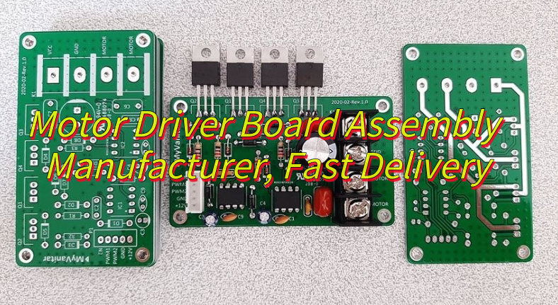
Why Is Contract Manufacturing For Electronic Printed Circuit Board Important For OEM Electronics?
Contract manufacturing for electronic printed circuit board projects is important because most OEMs do not want to build an internal factory for every product line. They want to focus on design, market access, software, system integration, or brand growth, while relying on specialized manufacturers for execution.
The value of contract manufacturing goes beyond labor. A strong manufacturing partner provides:
Process engineering
Procurement control
Quality management
Capacity flexibility
Compliance support
Delivery planning
Cost structure improvement
This is especially important when products move through multiple phases. The needs of EVT, DVT, PVT, pilot run, and recurring production are not identical. A contract manufacturing partner can help bridge those phases without forcing the OEM to rebuild the supply chain every time.
Here is why the model works well for OEM electronics:
OEM Need
Contract Manufacturing Advantage
Faster market launch
Existing process and factory setup
Lower fixed cost
No in-house line investment
Better sourcing reach
Stronger supplier network
Flexible production volume
Prototype to mass support
Quality discipline
Established control plans
For products involving electronic circuit board assembly, OEM buyers also benefit from process knowledge they may not fully maintain in-house. This includes soldering electronic circuit boards, fixture design, traceability systems, thermal process windows, and yield improvement methods.
The strongest contract manufacturers do more than build. They help prevent risk. That is why contract manufacturing remains important for OEM electronics, especially when reliability, speed, and supply-chain resilience all matter at the same time.
Why Choose EBest Circuit (Best Technology) For China Electronic Circuit Board Assembly Services?
Choosing a PCBA partner should come down to whether the supplier can help your team make better manufacturing decisions, not just whether they can place parts on a board. EBest Circuit (Best Technology) is built around that idea.
For China electronic circuit board assembly services, EBest combines engineering support, in-house manufacturing control, sourcing capability, and practical execution for prototype and low-volume OEM projects. The goal is simple: help engineers move faster while lowering avoidable manufacturing risk.
Key strengths include:
One-Stop Integration PCB fabrication, parts sourcing, PCBA assembly, and testing are coordinated in one system.
Prototype And Low-Volume Flexibility This is valuable for product validation, engineering change, and faster design iteration.
Complete Certifications ISO9001, ISO13485, IATF16949, and AS9100D support multi-industry requirements.
In-House Factory + Supplier Network Our PCB and PCBA factories work with 1000+ supply-chain partners to strengthen quality and lead-time control.
20 Years Of Experience We have supported 10,000+ engineers and served 1,800+ customers across different industries.
Fast PCBA Delivery Many projects can be supported with about 1.5-week rapid turnaround, depending on product complexity and material readiness.
For OEMs looking for electronic circuit board manufacturers that understand both engineering and delivery, EBest offers a more complete model than a simple assembly vendor. For quotation, file review, or project discussion, contact sales@bestpcbs.com.
In closing, China electronic circuit board assembly is far more than a sourcing phrase; it represents the full path from engineering files and component strategy to manufacturing control, testing discipline, and final product reliability. This article has shown how a strong supply chain supports better OEM outcomes through factory selection, assembly process control, current and thermal calculation, component management, UPS inverter applications, and pre-delivery testing.

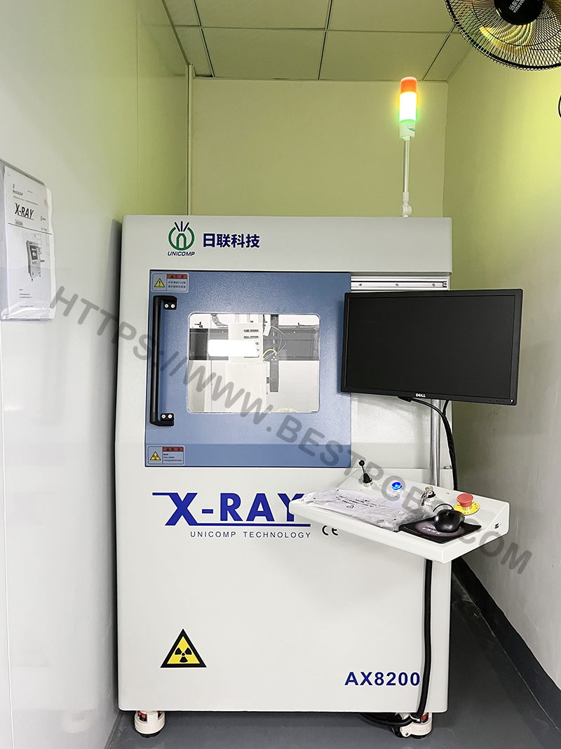
EBest Circuit (Best Technology) stands out with DFM and BOM optimization capability, in-house PCB and PCBA factories, 1000+ supply-chain partners, digital traceability, 20 years of manufacturing experience, and rapid PCBA turnaround for prototype and low-volume projects. To discuss your next China electronic circuit board assembly project, pls contact us via sales@bestpcbs.com.
FAQs About China Electronic Circuit Board Assembly
1. How do I choose a reliable China PCBA manufacturer?
When selecting a China electronic circuit board assembly partner, engineers usually evaluate several criteria: manufacturing capability, quality control system, engineering support, and communication efficiency. Reliable manufacturers typically provide DFM review, component sourcing assistance, automated inspection processes such as AOI or X-ray, and international certifications like ISO9001 or IATF16949.
2. What files are required for China electronic circuit board assembly?
To start a PCB assembly project, manufacturers normally require a set of engineering documents. These usually include Gerber files for PCB fabrication, a Bill of Materials (BOM) listing all components, pick-and-place files for SMT machines, and assembly drawings. Providing complete documentation helps avoid manufacturing errors and ensures faster production scheduling.
3. What should engineers check before sending PCB designs to China for assembly?
Before submitting a PCB design for assembly, engineers should review manufacturability and testability. Important checks include component spacing, solder mask clearance, footprint accuracy, and thermal management for high-power components. Many professional PCBA suppliers also provide Design for Manufacturing (DFM) feedback to optimize the design before mass production.
Industrial Control PCBA is critical for automation systems, providing stable signal control, high reliability, and long lifecycle performance. In this article, we will explore how industrial control PCBA works, what engineering requirements define reliable industrial controllers, and how manufacturers ensure stable long-term production for automation systems.
EBest Circuit (Best Technology) is a credible PCB and PCBA manufacturer with extensive industry mileage gained through 20 years of supporting demanding engineering projects across multiple industries. We work with many name-brand customers located in the United States, Germany, and Israel, delivering reliable manufacturing solutions tailored to their technical standards. By combining experienced engineering support, stable supply chains, and efficient production systems, EBest provides cost-effective PCB and PCBA services that help customers move from prototype to volume production.
What Makes Industrial Control PCBA Essential For Modern Automation Systems?
An industrial control PCBA is a printed circuit board assembly designed to manage and control industrial equipment. It integrates electronic components that perform signal processing, data communication, system monitoring, and device control.
Industrial control boards are widely used in:
PLC controllers
Robotics systems
Motor drives
CNC machines
Industrial IoT gateways
Power management equipment
These boards process sensor signals and control actuators such as motors, valves, or relays. They often communicate with upper-level systems like SCADA platforms or industrial networks.
A typical industrial controller PCBA includes:
Microcontrollers or industrial processors
Analog and digital signal circuits
Communication interfaces (RS485, CAN, Ethernet)
Power conversion circuits
Protection components and isolation circuits
Because industrial systems operate continuously, reliability becomes the most critical design goal. Even a small failure can interrupt production and cause significant economic losses.
What Performance Requirements Define Industrial Control Equipment PCBA In Harsh Environments?
Industrial environments place strict requirements on industrial control equipment PCBA. Unlike consumer electronics, these systems must maintain stable performance under difficult operating conditions.
Common environmental challenges include:
High temperature operation
Electrical noise from motors
Mechanical vibration
Dust and humidity
Unstable industrial power systems
To meet these requirements, engineers often design industrial PCBA with enhanced reliability features.
Key Performance Requirements
Requirement
Engineering Solution
Temperature tolerance
High Tg PCB materials and thermal design
Electromagnetic compatibility
Ground planes and EMI shielding
Electrical isolation
Optocouplers or digital isolators
Vibration resistance
Reinforced connectors and mechanical support
Power stability
Industrial grade voltage regulators
Many industrial boards operate in temperature ranges from -40°C to 85°C, and some specialized equipment must support even wider ranges.
Additionally, electromagnetic interference (EMI) from motors and inverters is common in factories. Engineers often use multi-layer PCB designs with dedicated ground planes to reduce noise and maintain signal integrity.
How Does Industrial Control Board PCBA Prototype Assembly Validate Hardware Before Mass Production?
Before large-scale manufacturing begins, engineers usually create a industrial control board PCBA prototype assembly. This prototype stage is critical for validating hardware design and ensuring system stability.
Prototype assembly allows engineers to evaluate several important aspects:
Hardware functionality
Signal integrity
Thermal performance
EMI compatibility
Firmware interaction
During this phase, engineers perform tests such as:
Functional testing of control algorithms
Communication interface verification
Thermal stress testing
Noise and EMI evaluation
If design issues are discovered, engineers can adjust PCB layout, component selection, or firmware configuration before mass production.
Prototype PCBA also helps verify manufacturability. Assembly engineers analyze solder joint quality, component placement accuracy, and potential production risks.
This early validation stage significantly reduces the risk of production defects and costly design changes later.
What Design Principles Ensure Reliable PCBA For Industrial Controller Systems?
Designing PCBA for industrial controller applications requires careful engineering decisions. Industrial controllers must remain stable during long operation cycles and under varying environmental conditions.
Several design principles are widely used in industrial PCBA development.
1. Robust Power Design
Industrial equipment often operates with fluctuating power sources. Engineers design multi-stage power regulation circuits to stabilize voltage supply.
Typical power architectures include:
DC-DC conversion modules
Over-voltage protection circuits
Reverse polarity protection
These circuits protect sensitive components from power disturbances.
2. Strong EMI And Noise Protection
Factories contain many electrical noise sources. Motors, inverters, and switching power supplies generate electromagnetic interference.
Engineers reduce EMI using several methods:
Multi-layer PCB grounding structure
Differential signal routing
Shielding and filtering circuits
Ferrite beads and common mode chokes
These design strategies ensure stable signal transmission.
3. Thermal Management
Industrial electronics often operate continuously. Heat accumulation can affect component reliability.
Thermal design techniques include:
Large copper planes
Thermal vias under power devices
Heat sinks and airflow design
Proper thermal design helps maintain long operating lifetimes.
4. Long Lifecycle Component Selection
Industrial systems often remain in service for more than ten years. Engineers choose components with long lifecycle availability to avoid redesign.
Industrial grade components also provide higher reliability compared with consumer parts.
How Is PCBA Industrial Controller Manufacturing Optimized For Long Lifecycle Products?
Manufacturing PCBA industrial controller boards requires strict process control. Industrial products demand consistent quality across many production cycles.
These structures improve electrical stability and thermal performance.
Precision SMT Assembly
Surface mount technology ensures accurate component placement. Automated equipment such as SPI, AOI, and X-ray inspection helps detect assembly defects early.
These tools ensure consistent manufacturing quality.
Supply Chain Management
Industrial control systems often require many electronic components. Professional manufacturers maintain strong supply chain networks to secure reliable component sourcing.
This reduces component shortages and production delays.
How To Evaluate A Professional Industrial Control PCBA Supplier For Stable Production?
Selecting the right industrial control PCBA supplier directly affects product reliability and long-term production stability.
Several key factors should be evaluated.
Manufacturing Experience
Industrial control electronics require specialized knowledge. Manufacturers with long industry experience better understand automation system requirements.
Quality Certifications
Reliable PCBA suppliers often maintain certifications such as:
These standards demonstrate structured quality management.
Engineering Support
Professional suppliers usually provide technical support including:
DFM review
PCB stackup recommendations
Assembly optimization
This collaboration improves overall product reliability.
Production Capacity
Industrial products may require both prototype and mass production. A strong PCBA partner should support flexible production volumes.
What Capabilities Should A PCBA Supplier For Industrial Control Provide To OEM Manufacturers?
A qualified PCBA supplier for industrial control should provide more than simple assembly services. Industrial systems require complete manufacturing support.
Important capabilities include:
Capability
Why It Matters
PCB fabrication
Integrated manufacturing improves quality control
Component sourcing
Reliable supply chain reduces production risk
SMT assembly
High precision assembly ensures stability
Functional testing
Ensures controller operation before shipment
Traceability systems
Supports long lifecycle product management
Manufacturers with integrated PCB and PCBA services can often provide faster production cycles and better process control.
In a nutshell, industrial automation continues to expand across manufacturing industries. Reliable electronics are essential for maintaining stable production systems. Industrial control PCBA plays a central role in controlling machines, processing signals, and managing industrial communication networks.
Designing and manufacturing these boards requires strong engineering expertise. Factors such as thermal design, EMI protection, robust power management, and strict testing procedures all contribute to long-term reliability.
Working with an experienced PCBA manufacturer helps automation companies reduce development risk and achieve stable product performance.
If you are looking for professional support for industrial controller electronics, feel free to contact our engineering team via sales@bestpcbs.com. Our team will be happy to assist with your industrial control PCB and assembly projects.
FAQs About Industrial Control PCBA
What Is Industrial Control PCBA?
Industrial control PCBA is a printed circuit board assembly designed for automation systems such as PLC controllers, robotics equipment, and industrial communication devices.
What Is The Difference Between Industrial PCBA And Consumer Electronics PCBA?
Industrial PCBA focuses on reliability and long-term operation. Consumer electronics prioritize cost and compact design.
Industrial boards often include stronger protection circuits and higher grade components.
How Long Does Industrial Controller PCBA Typically Last?
Many industrial controllers operate for 10 to 15 years when properly designed and maintained.
Long lifecycle components and robust PCB design help achieve this durability.
What PCB Materials Are Common For Industrial Control Boards?
Most industrial boards use high Tg FR-4 materials, while some power control systems may require thicker copper layers or specialized laminates.
These materials improve thermal stability and electrical performance.
How Important Is Testing In Industrial PCBA Manufacturing?
Testing is extremely important. Industrial controller boards often undergo AOI inspection, electrical testing, and functional testing to ensure stable operation.
These tests help detect manufacturing defects early.
This website uses cookies to enhance your experience, remember your preferences, and help us understand how visitors use our site. You can accept all cookies, reject non-essential cookies, or manage your settings.
This website uses cookies to improve your experience while you navigate through the website. Out of these cookies, the cookies that are categorized as necessary are stored on your browser as they are essential for the working of basic functionalities of the website. We also use third-party cookies that help us analyze and understand how you use this website. These cookies will be stored in your browser only with your consent. You also have the option to opt-out of these cookies. But opting out of some of these cookies may have an effect on your browsing experience.
Necessary cookies are absolutely essential for the website to function properly. These cookies ensure basic functionalities and security features of the website, anonymously.
Cookie
Duration
Description
cookielawinfo-checkbox-analytics
11 months
This cookie is set by GDPR Cookie Consent plugin. The cookie is used to store the user consent for the cookies in the category "Analytics".
cookielawinfo-checkbox-functional
11 months
The cookie is set by GDPR cookie consent to record the user consent for the cookies in the category "Functional".
cookielawinfo-checkbox-necessary
11 months
This cookie is set by GDPR Cookie Consent plugin. The cookies is used to store the user consent for the cookies in the category "Necessary".
cookielawinfo-checkbox-others
11 months
This cookie is set by GDPR Cookie Consent plugin. The cookie is used to store the user consent for the cookies in the category "Other.
cookielawinfo-checkbox-performance
11 months
This cookie is set by GDPR Cookie Consent plugin. The cookie is used to store the user consent for the cookies in the category "Performance".
viewed_cookie_policy
11 months
The cookie is set by the GDPR Cookie Consent plugin and is used to store whether or not user has consented to the use of cookies. It does not store any personal data.
Functional cookies help to perform certain functionalities like sharing the content of the website on social media platforms, collect feedbacks, and other third-party features.
Performance cookies are used to understand and analyze the key performance indexes of the website which helps in delivering a better user experience for the visitors.
Analytical cookies are used to understand how visitors interact with the website. These cookies help provide information on metrics the number of visitors, bounce rate, traffic source, etc.
Advertisement cookies are used to provide visitors with relevant ads and marketing campaigns. These cookies track visitors across websites and collect information to provide customized ads.