PCB manufacturing PCB manufacturing
Home > Blog

PCB Assembly

Custom PCB Design for Sensors: Signal, Power and Test Checks
Monday, July 13th, 2026
Custom sensor PCB design workbench with sensor board, oscilloscope and enclosure parts

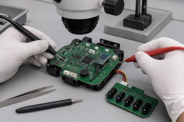
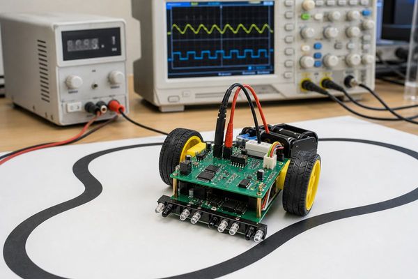
Custom PCB design for sensors should be reviewed around signal accuracy, low-noise power, grounding, connector placement, calibration access, test points, environmental protection and production-ready RFQ files. A sensor PCB is not only a small carrier board for a sensing element. It is the interface between the real world and the electronics that must read that signal consistently.

This guide is written for engineers and buyers preparing a custom sensor PCB or sensor PCBA for industrial devices, IoT products, environmental monitoring, equipment controls, medical-adjacent instruments, automotive modules or field equipment. It focuses on manufacturable board design and supplier review, not on selecting one specific sensor IC.

What does custom PCB design for sensors need to solve?

A sensor PCB needs to preserve the signal the sensor produces while surviving the mechanical, electrical and environmental conditions around the final product. The board may measure temperature, pressure, humidity, light, motion, gas, current, position or vibration, but the design checks follow a similar pattern: protect the signal path, control noise, provide stable power and make the board testable.

Low-current analog sensors may need guarded routing, short high-impedance traces and careful leakage control. Digital sensors may need clean I2C, SPI, UART, CAN, RS-485 or wireless module routing. Compact sensor products may use an HDI PCB when the enclosure is tight and the connector, MCU, RF section and sensing element compete for space.

Sensor board area PCB design check Buyer or engineer risk
Signal path Short routing, shielding, filtering, impedance or guard traces when needed Noise, drift or unstable readings can hide the real sensor output
Power supply Low-ripple rails, local decoupling, regulator heat and startup behavior Power noise can show up as false measurement changes
Grounding Analog/digital return paths, chassis connection and cable shield plan Ground loops or poor return paths can create hard-to-debug faults
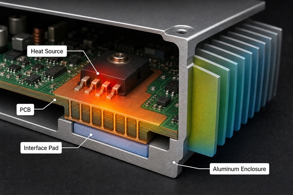
Environment Coating, enclosure interface, sensor exposure window and connector sealing Humidity, dust, chemicals or vibration can change readings or damage the board
Production test Test pads, calibration points, programming access and fixture clearance Good prototypes can become slow or inconsistent in volume builds

Which sensor applications need a custom PCB?

A custom PCB is useful when the sensor board must fit a product enclosure, meet a specific noise target, connect to a harness, support calibration or survive a defined operating environment. Evaluation boards are useful for early testing, but they rarely match the size, connector, grounding, power and protection requirements of the final product.

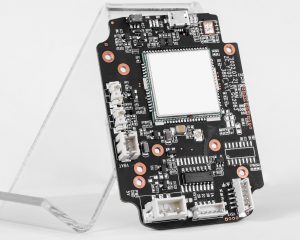
Common examples include environmental sensor nodes, industrial monitoring modules, battery and charger sensors, flow meters, load-cell interfaces, motor feedback boards, optical sensor boards, wearable sensor modules and equipment health monitoring electronics. Many designs can use an FR4 Printed Circuit Board. High-frequency, wireless or antenna-connected sensor products may need RF material decisions, controlled routing or a review against an RF PCB capability page.

How should low-noise layout be planned?

Low-noise sensor layout starts with floorplanning: keep the sensor front end, reference, ADC, filter, connector and noisy switching circuits in controlled zones. A layout can pass a simple connectivity check but still produce unstable data if switching regulators, antennas, motors, relays or long cable inputs couple noise into the measurement path.

Custom sensor PCB DFM review with schematic, connector cables and layout notes
Sensor PCB design should be reviewed as a complete signal chain, not only as a component placement task.

Place the sensor and analog front end close together when the signal is small. Keep high-current switching loops away from sensitive inputs. Use a continuous reference plane where possible, and avoid splitting a return path under critical traces without a clear reason. For cable-connected sensors, review ESD, surge, filtering and shield termination before release. If the design uses a flex tail or adhesive-mounted sensing element, confirm bend area, stiffener position and assembly handling early.

What power and grounding checks matter most?

Power and grounding checks should answer whether the sensor reading stays stable during startup, load changes, communication bursts and nearby switching events. Sensors that look accurate on a bench supply can become noisy when they share power with radios, relays, motors, LEDs, heaters or long cable harnesses.

Ask the designer or supplier to review regulator choice, decoupling placement, reference voltage routing, ground return, cable shield strategy and any required isolation. If a sensor board includes both sensitive analog inputs and digital communication, the layout should support both signal integrity and production assembly. When the order includes SMT, through-hole parts, connectors and final inspection, discuss the project as a Prototype PCB Assembly or production PCBA job instead of a bare PCB only.

How should connectors, cables and enclosures be designed?

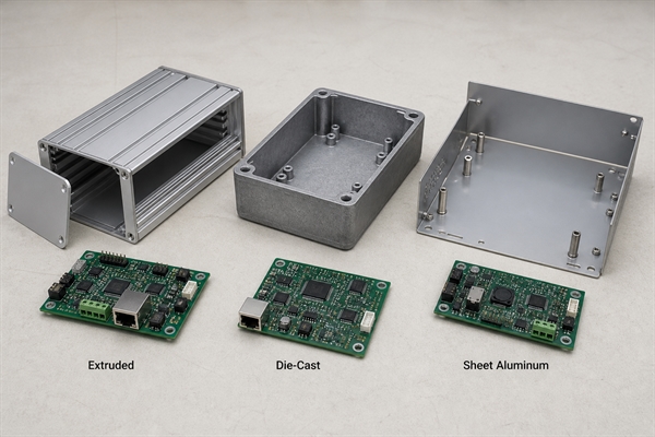
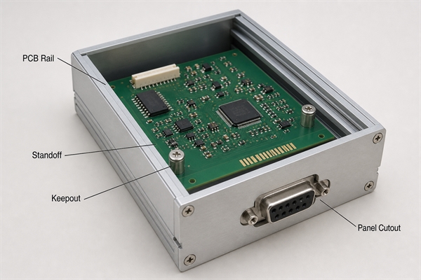
Sensor PCB reliability often depends on connector orientation, cable strain relief, enclosure clearance and how the sensor is exposed to the measured environment. A board can be electrically correct but hard to assemble if the cable exits the wrong side, the sensor window does not align, or the test pads are blocked by the housing.

Before fabrication, compare the PCB outline with the enclosure model, mounting bosses, gasket, sensor opening, cable routing and service access. For field devices, define whether the board needs conformal coating, potting, a vented enclosure, connector sealing or a separate daughterboard. If the supplier is expected to assemble the PCB into a housing or harness, treat the RFQ as a Box Build Assembly discussion.

When do flex or rigid-flex sensor boards make sense?

Flex and rigid-flex sensor boards make sense when the sensing element must sit away from the main electronics, bend around a shape, reduce connector count or fit a compact enclosure. They are common in wearables, medical-adjacent devices, compact industrial sensors, optical modules, probes and adhesive-mounted sensing assemblies.

Flex is not a shortcut around mechanical design. Bend radius, copper direction, stiffener location, adhesive choice, strain relief and assembly sequence still need review. If a sensor product uses a flexible circuit, compare the design against a proven custom flex PCB design checklist before ordering production tooling.

What should be included in the sensor PCB test plan?

The test plan should prove that the board can be fabricated, assembled, programmed, calibrated and checked repeatedly before it reaches the final product. For sensor PCBA, continuity alone is usually not enough. The test may need known input conditions, reference measurements, firmware loading, communication checks and pass/fail limits.

Sensor PCBA functional testing with oscilloscope, test fixture and environmental sensor enclosure
Plan functional test and calibration access before the board is released for production.

Add test pads for power rails, ground, programming, communication lines and critical analog nodes. Keep them reachable after assembly and enclosure installation. If calibration is needed, define the calibration input, equipment, firmware state and acceptable tolerance. A supplier’s PCB test equipment and fixture planning should be discussed before volume production, not after failed boards appear.

RFQ checklist for custom sensor PCB design

A strong RFQ package lets the supplier review sensor accuracy, manufacturability, assembly risk and test coverage before quoting price and lead time. Send controlled files instead of screenshots or partial exports.

  1. Gerber files, drill files, netlist and controlled revision number.
  2. Schematic, stackup, copper weight, board thickness and surface finish requirement.
  3. Sensor type, expected signal range, accuracy goal and calibration requirement.
  4. Power input range, current load, regulator notes and any battery or charger interface.
  5. Connector, cable, enclosure, coating, potting or gasket information.
  6. BOM, approved alternates, centroid file and assembly drawing for PCBA.
  7. Programming method, firmware loading requirement and functional test criteria.
  8. Environmental notes such as temperature, humidity, vibration, dust, chemicals or outdoor exposure.

Supplier questions buyers should ask

The best supplier questions force a real DFM and test review instead of a generic board price. Use them before approving the first build.

  • Which parts of this sensor design create the highest layout or assembly risk?
  • Are the sensor, connector and enclosure clearances consistent with the mechanical file?
  • Do any analog inputs need additional spacing, guarding, shielding or cleaning controls?
  • Are the test pads reachable after assembly and enclosure installation?
  • Which components have sourcing risk or need approved alternates?
  • Can the test fixture simulate or verify the sensor input reliably?
  • What should change before moving from prototype to pilot production?

Sensor boards often depend on stable parts. If a project uses specialized sensor ICs, connectors, filters, references or wireless modules, involve Component Sourcing early so substitutes do not change measurement behavior without engineering approval.

FAQ

What is custom PCB design for sensors?

Custom PCB design for sensors means designing a circuit board around a sensing element, signal chain, power system, connectors, firmware access and test plan for a specific product. The goal is to read the sensor accurately and build the board repeatedly, not just connect a sensor IC to a controller.

Does every sensor PCB need a four-layer board?

No. Simple low-speed digital sensor boards may work on two layers when routing, power and grounding are clean. Mixed-signal, wireless, compact or low-noise sensor boards often benefit from four or more layers because a stable reference plane and controlled return paths reduce layout risk.

What causes noise in sensor PCB readings?

Common causes include unstable power rails, poor grounding, long high-impedance traces, switching regulator noise, nearby motors or relays, cable pickup, weak shielding, poor filtering and bad test setup. The fix depends on the sensor type and signal level, so schematic and layout review should happen before fabrication.

What files are needed for a sensor PCB quote?

Send Gerber and drill files, schematic, stackup, board drawing, BOM, centroid file, assembly drawing, enclosure notes and test requirements. If calibration, coating, potting, firmware loading or box build is required, include those details in the first RFQ.

Can a PCB supplier improve sensor accuracy?

A PCB supplier can help with manufacturability, material choice, assembly quality, inspection and repeatable testing. Accuracy still depends on the sensor IC, circuit design, layout, calibration method, firmware and operating environment. Treat supplier feedback as one part of the engineering review.

Conclusion

Custom PCB design for sensors should start with the measurement problem, not with board price. Define the signal, power rails, grounding, enclosure, connector, calibration and test plan before production files are released. Then ask the supplier to review manufacturability and assembly risk against the real use case. That process gives the sensor board a better chance of producing stable readings in the final product.

You may also like

Custom PCB Assembly Services Checklist
Sunday, July 12th, 2026
Custom PCB assembly services with assembled circuit boards, SMT equipment and BOM review
Custom PCB assembly services are easier to quote and control when the BOM, design files, sourcing plan and test requirements are clear before production.

Custom PCB assembly services turn a bare printed circuit board, component list and assembly data into a working PCBA built for a specific product. A useful assembly order is not defined only by quantity and delivery date. It depends on a clean BOM, verified footprints, component availability, DFM review, soldering method, inspection plan, functional test needs and clear acceptance criteria.

For buyers and hardware teams, the right question is not only “who can assemble this PCB?” A better question is “what information does the assembly supplier need to build the first batch without guessing?” This checklist explains the files, engineering checks, sourcing decisions, quality controls and RFQ questions that should be settled before custom PCBA production starts.

What Are Custom PCB Assembly Services?

Custom PCB assembly services cover the process of mounting and soldering components onto a customer-specific PCB, then inspecting and testing the assembled board against the product requirement.

The service may include SMT assembly, through-hole assembly, mixed-technology assembly, BGA placement, cable or wire soldering, conformal coating, programming, box-build steps, component sourcing and functional testing. For a simple prototype, the supplier may only need Gerbers, a BOM and a pick-and-place file. For a production PCBA, the supplier also needs revision control, approved alternates, test fixtures, packaging requirements and a clear defect-handling process.

A bare PCB can look correct and still fail after assembly if the footprint, pad design, component height, thermal relief, polarity marking or soldering process was not checked early. That is why custom assembly should be treated as an engineering workflow, not just a labor quote.

Files Needed Before a PCBA Supplier Can Quote Accurately

A PCBA quotation is only reliable when the supplier can see the board design, component demand and assembly method without filling gaps by assumption.

At minimum, send Gerber or ODB++ files, NC drill data, a BOM with manufacturer part numbers, quantity, designator and package, a centroid or pick-and-place file, assembly drawings, polarity notes, special soldering notes, test requirements and the target quantity. If the project has critical parts, include approved substitutes, lifecycle notes and any customer-supplied material plan.

PCB assembly BOM and DFM review with circuit layout, component reels and assembled boards
BOM, centroid, Gerber and assembly drawing review should happen before components are purchased or the SMT line is scheduled.

Common quoting problems include obsolete parts, inconsistent package names, missing polarity, a centroid file that does not match the latest Gerbers, unclear do-not-populate parts, no test method, and a requested delivery date that ignores component lead time. Best Technology’s Component Sourcing page is a useful internal reference when a project needs turnkey sourcing instead of consigned parts.

BOM Review Comes Before Assembly Scheduling

BOM review should confirm that every part can be bought, placed, soldered and inspected before the assembly job is released.

A practical BOM review checks manufacturer part numbers, distributor availability, package consistency, moisture sensitivity, polarity, lifecycle risk, RoHS or other compliance needs, approved alternates and customer-supplied parts. It should also separate no-load parts, optional variants and parts that need special storage or handling. For prototypes, this prevents delays. For repeat builds, it reduces the chance of silent substitutions and batch-to-batch variation.

BOM Item What to Check Why It Matters
MPN and package Manufacturer part number, footprint, pin count and package code. Wrong packages cause placement errors or unusable boards.
Availability Stock, lead time, MOQ and approved substitutes. Component shortages can delay assembly more than PCB fabrication.
Polarity and orientation Diodes, LEDs, ICs, connectors, electrolytic capacitors and batteries. Orientation mistakes can damage the product during first power-up.
Special handling MSL level, baking needs, ESD controls and storage limits. Moisture or handling problems can create hidden reliability defects.
Test relevance Parts tied to programming, calibration or functional test. Testing cannot be planned correctly if critical parts are not identified.

DFM and DFA Checks That Prevent Assembly Rework

DFM and DFA checks should focus on placement, solderability, inspection access and test access before the first board enters production.

  • Confirm solder paste openings for fine-pitch ICs, QFN packages and thermal pads.
  • Check BGA escape routing, via-in-pad treatment and X-ray inspection needs.
  • Review component spacing, connector keep-out areas and tall part interference.
  • Verify fiducials, panel rails, tooling holes and board support for SMT handling.
  • Check test points for programming, ICT, functional test or power rail measurement.
  • Review through-hole clearances for wave soldering, selective soldering or hand soldering.
  • Confirm polarity marks are visible after assembly and not hidden under components.

When the design includes dense IC packages, early review of BGA Assembly requirements can prevent problems with pad design, X-ray inspection, rework access and thermal profile control.

SMT, Through-Hole and Mixed Assembly Need Different Planning

The correct assembly method depends on component package, mechanical strength, thermal demand, production volume and inspection requirements.

Assembly Type Best Fit Buyer Check
SMT assembly Most modern ICs, passives, sensors, communication modules and compact products. Confirm stencil, fiducials, placement accuracy and reflow profile needs.
Through-hole assembly Connectors, power parts, large capacitors and mechanically stressed parts. Confirm wave, selective or manual soldering and keep-out clearance.
Mixed assembly Boards with both SMT and through-hole devices. Confirm process order, hand-solder risk and cleaning requirements.
Box-build support PCBAs that must be wired, enclosed, programmed or packed as a module. Confirm drawings, cable routing, labeling, fixture needs and final test steps.

If the project must move from engineering samples to repeated builds, Prototype PCB Assembly and Quick Turn PCB Assembly pages are relevant internal references for prototype and schedule-sensitive PCBA planning.

This SMT workflow video is included as a process supplement; the file, BOM, DFM and test requirements still need to be defined in writing before RFQ.

Inspection and Testing Should Be Defined Before Production

Inspection and testing should match the product risk, not a generic pass-fail line in the purchase order.

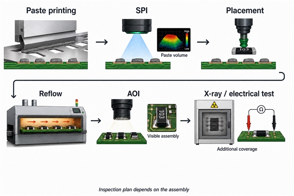
Typical PCBA checks include solder paste inspection when needed, first-article inspection, AOI, X-ray for BGA or hidden joints, visual inspection, programming, power-on check, ICT, flying probe, functional test, burn-in or environmental screening when the application requires it. The buyer should define which tests are included, which reports are required, and what happens when a board fails.

PCB assembly testing and inspection with assembled circuit boards in a test fixture
Functional checks, AOI, X-ray and fixture-based testing should be planned according to the risk level of the PCBA.

For projects where test coverage affects acceptance, Best Technology’s PCB test equipment page can help buyers understand common inspection and test resources. The article should not replace a project-specific test plan, but it gives useful vocabulary for RFQ discussions.

Cost and Lead Time Drivers in Custom PCB Assembly Services

Assembly cost and lead time are usually driven by component sourcing, placement complexity, test requirements and rework risk rather than board quantity alone.

Main cost drivers include BOM line count, fine-pitch packages, BGA or QFN devices, double-sided assembly, through-hole soldering, conformal coating, programming, functional test fixtures, component shortages, consigned material handling, packaging and urgent delivery. A low assembly price can become expensive if it excludes sourcing review, test setup or failure analysis support.

Buyers should ask the supplier to separate PCB fabrication, component sourcing, SMT assembly, through-hole assembly, testing, programming, packaging and freight. That makes it easier to compare quotes and identify where the real risk sits.

RFQ Questions to Ask a Custom PCBA Supplier

Good RFQ questions reveal whether the supplier understands the assembly risk before the purchase order is issued.

  • Are any parts obsolete, long-lead, high-risk or missing approved substitutes?
  • Do the BOM, centroid file, Gerbers and assembly drawings match the same revision?
  • Which DFM or DFA issues should be fixed before production?
  • Which soldering process will be used for SMT, through-hole and mixed components?
  • Which inspection steps are included, and which need a separate request?
  • Can the supplier support first-article approval before the full batch?
  • What test data, photos, reports or failure feedback will be provided?
  • How will customer-supplied parts, shortages and alternate parts be controlled?

For turnkey projects, the main service page for PCB assembly support should be reviewed together with the quote, because sourcing, assembly, inspection and testing are connected decisions.

FAQ

What files do I need for custom PCB assembly services?

You usually need Gerber or ODB++ files, NC drill files, a BOM with manufacturer part numbers, a centroid file, assembly drawings, polarity notes and test requirements. For turnkey assembly, include approved substitutes and any customer-supplied material list.

Is custom PCB assembly the same as PCB fabrication?

No. PCB fabrication makes the bare board. PCB assembly mounts and solders components onto that board. A complete PCBA project may include both steps, plus component sourcing, inspection, programming and functional testing.

What causes delays in PCB assembly projects?

Common delays come from obsolete parts, missing BOM data, mismatched file revisions, unclear polarity, unavailable substitutes, DFM problems, missing test fixtures and late design changes. Component sourcing often controls the schedule more than SMT placement time.

Should I use consigned or turnkey PCB assembly?

Use consigned assembly when you already control parts and want the supplier to assemble them. Use turnkey assembly when you want the supplier to source components, manage purchasing risk and coordinate fabrication, assembly and testing.

When is X-ray inspection needed for PCBA?

X-ray inspection is useful for BGA, QFN, hidden solder joints, via-in-pad structures and assemblies where solder quality cannot be judged visually. It should be specified before quotation if it is part of acceptance.

How can I reduce custom PCB assembly cost?

Clean the BOM, approve alternates, avoid unnecessary special handling, design for accessible testing, reduce avoidable hand soldering, confirm footprints early and separate required tests from optional reports. Do not remove checks that protect product reliability.

What should be checked before first-article approval?

Check component values, polarity, solder joints, connector orientation, programming status, power rails, functional behavior, mechanical fit, labeling and packaging. Any deviation should be corrected before the remaining quantity is released.

Final Thoughts

Custom PCB assembly services work best when the supplier receives clear files, a controlled BOM, realistic process requirements and a defined inspection plan before production. A complete RFQ does not slow the project down. It reduces avoidable clarification, rework and delivery risk.

If you are preparing a prototype, pilot build or production PCBA, send your Gerber files, BOM, centroid file, assembly drawings and test requirements to the Best Technology engineering team at sales@bestpcbs.com for review and quotation support.

You may also like

PCB vs PCBA: Bare Board, Assembly and Sourcing Differences
Thursday, July 9th, 2026

ο»Ώ

PCB vs PCBA: What Is the Difference?

A PCB is the bare printed circuit board: copper traces, solder mask, pads, vias, holes and surface finish, but no assembled electronic components. A PCBA is the completed assembly after components are mounted and soldered onto the PCB, then inspected and tested. In sourcing terms, PCB usually means bare board fabrication, while PCBA means PCB fabrication plus component procurement, SMT or through-hole assembly, inspection and functional checks.

This PCB vs PCBA guide explains the difference from an engineering and purchasing point of view, so you know what to request, what files to prepare and how each choice affects cost, lead time and quality control.

PCB vs PCBA comparison with a bare PCB on the left and assembled PCBA on the right
PCB means the bare board; PCBA means the assembled board with components, solder joints and testing.

What Is a PCB?

A PCB, or printed circuit board, is the physical platform that connects electronic components through copper traces. It may include laminate material, copper layers, solder mask, silkscreen, plated holes, vias, pads, slots and a surface finish such as HASL, ENIG or OSP.

A bare PCB does not perform the final product function by itself. It is the circuit carrier. Before components are added, the factory can inspect board dimensions, copper quality, solder mask registration, hole plating, impedance requirements and electrical continuity. For buyers, a PCB order usually requires Gerber files, drill files, stackup notes and fabrication specifications.

What Is a PCBA?

A PCBA, or printed circuit board assembly, is the PCB after electronic components have been installed and soldered. It may include SMT components, through-hole components, connectors, cables, heat sinks, firmware programming and test records depending on the project scope.

PCBA work is more than placing parts on a board. The supplier must manage component sourcing, stencil setup, solder paste printing, pick-and-place, reflow, through-hole soldering when needed, AOI, X-ray for some packages, cleaning if required, inspection and functional testing. For buyers, a PCBA order usually needs Gerber files, BOM, pick-and-place data, assembly drawings and test requirements.

PCB vs PCBA: The Core Difference

The core difference is assembly status. PCB is the bare board before components; PCBA is the assembled and tested electronic board after components are installed.

PCB vs PCBA definition graphic explaining bare board and assembled board differences
The move from PCB to PCBA adds component sourcing, assembly, soldering, inspection and testing.
Item PCB PCBA
Meaning Bare printed circuit board Printed circuit board assembly
Components No assembled components Components mounted and soldered
Main factory work Board fabrication Fabrication, sourcing, assembly and test
Files usually needed Gerber, drill, stackup notes Gerber, BOM, pick-and-place, assembly notes, test plan
Quality focus Trace, hole, solder mask, surface finish, electrical test Solder joints, polarity, component value, function and reliability
Best for Board-only fabrication or buyer-managed assembly Turnkey prototypes, samples, validation and production builds

How a PCB Becomes a PCBA

A PCB becomes a PCBA when the bare board moves through component sourcing, solder paste printing, SMT placement, reflow soldering, through-hole assembly when needed, inspection and testing.

Process flow from PCB fabrication to component sourcing, SMT assembly, inspection and PCBA delivery
PCBA delivery adds assembly and test steps after bare PCB fabrication.

For SMT assembly, solder paste is printed through a stencil, components are placed by machine, and the board goes through reflow. Through-hole components may be soldered by wave soldering, selective soldering or manual soldering depending on volume and design. After that, inspection and testing confirm whether the assembled board meets the order requirements.

Which One Should You Order: PCB or PCBA?

Order a PCB when you only need the bare board or when your team will buy components and assemble the boards elsewhere. Order PCBA when you want one supplier to manage the board, parts, assembly and test process.

PCB-only orders make sense when you already have assembly capability, want to control component purchasing, or need bare boards for internal trials. PCBA is usually better when you need working samples, production builds, functional testing, less handoff risk or one quotation that includes more of the manufacturing work.

The wrong scope can waste time. If you request PCB when you really need PCBA, you may receive good bare boards but still have no working units. If you request PCBA without a clean BOM and assembly data, the supplier may need extra clarification before quoting or building.

Cost Difference Between PCB and PCBA

PCB cost is usually driven by board size, layer count, material, copper thickness, surface finish, hole requirements, impedance control, panelization and quantity. PCBA cost adds component cost, sourcing risk, stencil, placement, soldering, inspection, test fixture needs and labor.

For simple boards, the bare PCB may be a small part of the total assembled product cost. For complex assemblies, component availability and testing can matter more than board fabrication price. Buyers should compare quotes by scope, not by headline price. A PCB quote and a PCBA quote are not equivalent unless the included work is the same.

Quality Control: PCB vs PCBA

PCB quality control checks whether the bare board was fabricated correctly. PCBA quality control checks whether the full assembled circuit was built correctly and can work as intended.

For PCB fabrication, common checks include electrical test, visual inspection, hole plating review, solder mask inspection and dimensional checks. For PCBA, the inspection scope may include solder paste quality, component placement, polarity, solder joint quality, AOI, X-ray for hidden joints, ICT or functional testing. The more complete the assembly, the more important test planning becomes.

Files Needed for PCB and PCBA Quotes

PCB and PCBA quotes need different document packages. Sending the right files early helps avoid delays and wrong assumptions.

  • For PCB: Gerber files, drill files, board thickness, copper weight, layer count, material, surface finish, solder mask color and special requirements.
  • For PCBA: PCB files plus BOM, pick-and-place file, assembly drawing, component polarity notes, programming requirements, test plan and packaging requirements.
  • For turnkey PCBA: approved alternates, manufacturer part numbers, substitute rules and critical component notes are especially useful.

Common Buyer Mistakes

Many PCB vs PCBA problems happen because the order scope is unclear. A buyer may ask for a PCB quote while expecting assembled boards, or send a BOM without confirming footprints and polarity.

Before requesting a quote, decide whether you need bare boards, consigned assembly, turnkey PCBA, prototype assembly or mass production. Check that every component in the BOM has a package, value, manufacturer part number when needed and a matching footprint. If the board needs firmware, test points or a fixture, mention that before production starts.

FAQ

Is PCB the same as PCBA?

No. PCB means the bare printed circuit board. PCBA means the printed circuit board assembly after components are mounted, soldered, inspected and tested.

What does PCBA stand for?

PCBA stands for printed circuit board assembly. It refers to a PCB that has been assembled with electronic components and is ready for inspection, testing or product integration.

Can I order PCB fabrication without assembly?

Yes. If you only need bare boards, order PCB fabrication. You will still need a separate assembly plan if the boards must become working electronics.

What files are needed for PCBA?

PCBA usually needs Gerber files, drill files, BOM, pick-and-place data, assembly drawings, polarity notes and test requirements. Turnkey assembly also needs clear component sourcing rules.

Why is PCBA more expensive than PCB?

PCBA includes more work: component sourcing, stencil, SMT or through-hole assembly, soldering, inspection, testing and handling. The components themselves can also cost more than the bare board.

Which is better for prototypes, PCB or PCBA?

If you only want to check board fabrication, PCB is enough. If you need working samples for validation, firmware, testing or customer review, PCBA is usually the right scope.

Does PCBA include functional testing?

Not always. Functional testing must be defined in the order scope. Some PCBA orders include only assembly and visual inspection, while others include ICT, programming or custom functional tests.

Can the same supplier handle PCB and PCBA?

Yes, many suppliers can support both PCB fabrication and PCBA. This can reduce handoff issues, but the buyer still needs to provide complete files, approved components and clear test requirements.

Final Thoughts

The simplest way to remember PCB vs PCBA is this: PCB is the board, PCBA is the assembled electronic board. If you need only fabricated boards, request PCB. If you need working assemblies, request PCBA with BOM, placement data and test requirements.

If you are sourcing PCB fabrication or turnkey PCBA for prototypes, sample builds or production, BestPCBs can help review fabrication details, assembly requirements and quotation scope. Contact the engineering team at sales@bestpcbs.com for technical support and a quote.

You may also like

Wire Bonding Gold Wire for High-Reliability PCB and PCBA Projects
Wednesday, June 3rd, 2026

Wire bonding gold wire is a fine gold wire used to connect a chip, die, sensor, module, or substrate pad when standard soldering is not the best connection method. This blog mainly explains how wire bonding gold wire is used in high-reliability PCB and PCBA projects, what process, material, and surface finish requirements should be checked, and how EBest Circuit (Best Technology) supports engineering review, PCB fabrication, PCBA assembly, and testing.

EBest Circuit (Best Technology) supports high-reliability PCB and PCBA projects that involve wire bonding requirements, including PCB fabrication, surface finish review, DFM checking, PCBA assembly, component sourcing, testing, and production traceability. If your project needs a bondable PCB, ceramic substrate, RF module board, sensor board, or high-reliability assembly, you can send Gerber files, BOM, drawings, and requirements to sales@bestpcbs.com for engineering review.

Wire Bonding Gold Wire

What Is Wire Bonding Gold Wire?

Wire bonding gold wire is a very thin gold wire used to make electrical connections between a small electronic device and a circuit pad. It is common when the design uses bare die, chip-on-board, hybrid circuits, sensors, RF modules, or special high-reliability packages.

In simple words:

  • It works like a tiny bridge.
    It connects the chip or die to the PCB, ceramic substrate, package, or module pad.
  • It is used where soldering is not suitable.
    Some chips are too small, too delicate, or too specialized for normal SMT soldering.
  • It needs a bondable surface.
    The PCB pad cannot be treated like a normal soldering pad only. The surface finish must be suitable for wire bonding.
  • It is part of the whole PCB/PCBA design.
    Gold wire bonding is not just a material choice. It affects pad design, surface finish, substrate material, assembly process, and testing.

Common project types include:

  • Bare die assembly
    Used when a chip is mounted directly on a board or substrate.
  • Ceramic substrate modules
    Used in high-heat, high-power, RF, sensor, and precision circuits.
  • RF and microwave modules
    Used where short and stable electrical paths are important.
  • Medical and industrial electronics
    Used when reliability, traceability, and long service life matter.
  • Automotive and aerospace electronics
    Used in demanding environments where process stability is important.

For customers, the main point is this: if your project needs gold wire bonding, the PCB must be designed and manufactured for it from the beginning.

EBest Circuit (Best Technology) can review bonding pad design, PCB material, surface finish, stack-up, solder mask clearance, and assembly requirements before production. This helps reduce trial-and-error during prototype and batch production.

Why Is Gold Used in Wire Bonding for Electronics and IC Chips?

Gold is used because it is easy to bond, stable, conductive, and resistant to oxidation. For many high-reliability electronics, these properties make gold bonding wire a dependable choice.

Gold is selected for several clear reasons:

  • Good electrical conductivity
    Gold helps signals and current pass through fine connections with stable performance.
  • Strong oxidation resistance
    Gold does not easily form an oxide layer, so the bonding surface stays more stable.
  • Good ductility
    Gold wire can be shaped into loops and bonded without breaking easily.
  • Mature bonding process
    Gold ball bonding is widely used and well understood in microelectronics manufacturing.
  • Reliable long-term performance
    It is suitable for products that need stable operation over long service life.

Gold wire bonding is often used in:

  • IC chips
  • Sensor modules
  • RF devices
  • Hybrid circuits
  • Ceramic substrates
  • Optoelectronic modules
  • Medical electronic modules
  • Automotive sensors
  • Aerospace electronics
  • Industrial control modules

For PCB and PCBA buyers, the important question is not only β€œWhy use gold?” The better question is:

Can the PCB pad, surface finish, and assembly process support stable gold wire bonding?

That is where manufacturing support becomes important. EBest Circuit (Best Technology) can help customers check whether the board material, pad finish, and production documents match the bonding requirement before the PCB is fabricated.

How Does the Gold Wire Bonding Process Work?

Gold wire bonding connects one pad to another using heat, pressure, ultrasonic energy, and a fine gold wire. The process sounds complex, but the basic idea is simple: press the gold wire onto a clean metal pad and create a stable metal-to-metal connection.

A typical gold ball wire bonding process works like this:

  • Step 1: The gold wire is fed through a bonding tool.
    The tool guides the wire to the correct pad position.
  • Step 2: A small gold ball is formed.
    The end of the wire is melted into a tiny ball.
  • Step 3: The first bond is made.
    The gold ball is pressed onto the chip pad or substrate pad.
  • Step 4: The wire loop is formed.
    The machine moves to the second pad and creates a controlled wire loop.
  • Step 5: The second bond is made.
    The wire is bonded to the second pad, then cut.
Wire Bonding Gold Wire

The quality of this process depends on a few practical factors:

  • Pad surface must be clean.
  • Pad finish must be bondable.
  • Pad size must match the wire and tool.
  • Substrate must stay stable during bonding.
  • Wire loop height must have enough clearance.
  • Bonding parameters must be controlled.
  • Inspection and testing must confirm bond quality.

For a PCB project, these details should be confirmed before production. If the board is already made with the wrong finish or poor pad design, bonding problems may appear during assembly.

EBest Circuit (Best Technology) supports this stage through DFM review, fabrication drawing review, surface finish checking, PCB manufacturing, PCBA assembly, and testing coordination. For high-reliability projects, MES traceability can also help track materials, production status, and quality records.

Gold Ball Wire Bonding vs Gold Wedge Wire Bonding: What Is the Difference?

Gold ball wire bonding and gold wedge wire bonding are two common bonding methods. The main difference is the tool shape, bond shape, loop style, and application.

ItemGold Ball Wire BondingGold Wedge Wire Bonding
ToolCapillaryWedge tool
First bondBall-shapedWedge-shaped
SpeedUsually fasterUsually slower
DirectionMore flexibleMore directional
Loop profileMedium or higher loopLower loop possible
Common useIC packaging, chips, sensorsRF, power modules, special layouts

Gold ball wire bonding is common in IC packaging and microelectronics because it is fast, mature, and flexible. It works well when many fine connections are needed.

Wire Bonding Gold Wire

Gold wedge wire bonding is often used when the design needs a lower wire loop or more controlled wire direction. It can be useful in RF modules, power devices, and compact circuits.

For PCB design, the bonding method affects:

  • Pad size
  • Pad spacing
  • Pad orientation
  • Wire loop height
  • Clearance around the bonding area
  • Surface finish requirement
  • Inspection method

A simple rule:

Ball bonding is often chosen for speed and flexibility. Wedge bonding is often chosen for low-profile or special layout control.

EBest Circuit (Best Technology) can help customers review the PCB layout based on the expected bonding method. This includes checking pad opening, solder mask clearance, material stability, and whether the board structure is suitable for the assembly process.

What Temperature and Surface Finish Are Needed for Gold Wire Bonding?

Gold wire bonding needs the right temperature and the right pad surface. The exact process window depends on the bonding machine, wire size, pad material, substrate, and reliability requirement.

For customers, the most important point is this:

A normal solderable PCB surface is not always suitable for gold wire bonding.

Surface finish must be selected carefully.

Common surface finishes related to wire bonding include:

Surface FinishKey Point
Electrolytic soft goldCommon for bondable gold pads
ENEPIGOften suitable for soldering and wire bonding
ENIGMust be reviewed carefully
Nickel goldCan work when thickness and process are controlled
Thick gold platingUsed when stronger bondable gold layer is needed

When choosing the surface finish, check these items:

  • Gold thickness
    The gold layer must be suitable for bonding, not only for corrosion protection.
  • Gold hardness
    Soft gold is often preferred for bonding because it forms a better bond.
  • Nickel layer quality
    Nickel can act as a barrier layer, but poor plating may affect reliability.
  • Pad cleanliness
    Contamination can weaken the bond.
  • Solder mask clearance
    The bonding tool needs enough open space around the pad.
  • Storage and packaging
    Bonding surfaces should be protected from scratches, oxidation, and contamination.

Different PCB materials also behave differently during bonding:

  • FR4 PCB
    Suitable for many standard electronic products. For bonding projects, heat resistance and dimensional stability should be checked.
  • High-Tg FR4 PCB
    Better for projects with higher thermal stress or stricter assembly requirements.
  • Ceramic PCB
    Suitable for high heat, high power, sensor, RF, and precision applications.
  • Metal core PCB
    Used for thermal management in LED, power, and high-current products.
  • RF PCB
    Used when signal behavior and controlled dielectric performance matter.
  • Rigid-flex PCB
    Used when the product needs a compact structure and flexible connection.

EBest Circuit (Best Technology) can manufacture and assemble multiple board types, including FR4 PCB, high-Tg PCB, ceramic PCB, aluminum PCB, copper substrate PCB, RF PCB, rigid-flex PCB, and multilayer PCB. For wire bonding-related projects, our team can review surface finish, pad design, material choice, and assembly notes before production.

How Do Gold, Aluminum, and Copper Wire Bonding Compare?

Gold, aluminum, and copper can all be used for wire bonding. Each material has its place. The right choice depends on the pad material, product requirement, current load, cost target, and reliability level.

MaterialMain StrengthTypical Consideration
GoldStable and easy to bondHigher material cost
AluminumCost-effective for many power usesOxidation control matters
CopperGood conductivity and lower costProcess control is stricter

Gold wire bonding is often selected when reliability, corrosion resistance, and process stability are important.

Best-fit applications include:

  • IC chips
  • Sensors
  • RF modules
  • Medical electronics
  • Aerospace electronics
  • Ceramic substrate modules
  • High-reliability assemblies

Aluminum wire bonding is common in power devices and some wedge bonding applications.

Best-fit applications include:

  • Power modules
  • Automotive power electronics
  • High-current devices
  • Some semiconductor packages

Copper wire bonding is used when conductivity and cost control are important, especially in high-volume semiconductor packaging.

Best-fit applications include:

  • Consumer IC packages
  • High-volume electronics
  • Cost-sensitive semiconductor products

The decision should not be based only on wire price. A good material choice should consider:

  • Bond pad material
  • Surface finish
  • Operating temperature
  • Current requirement
  • Product life cycle
  • Vibration or shock
  • Thermal cycling
  • Inspection method
  • Batch quantity
  • Reliability test standard

For PCB and PCBA projects, the bonding wire must match the board finish and assembly process. EBest Circuit (Best Technology) can support early engineering review so the PCB is manufactured with the correct pad finish, material structure, and process notes.

How to Choose Gold Bonding Wire by Diameter, Resistance, and Cost?

Choosing gold bonding wire is mainly about three things: wire size, electrical performance, and project cost. The goal is not to choose the thinnest or cheapest wire. The goal is to choose a wire that works reliably with the PCB, pad, chip, and assembly process.

When reviewing gold bonding wire, focus on these points:

  • Wire diameter
    Thin wire is useful for small pads and fine-pitch designs. Thicker wire can carry more current and provide stronger mechanical performance.
  • Pad size
    The pad must be large enough for the selected wire and bonding tool.
  • Current requirement
    Higher current may need larger wire, shorter loop length, or better heat dissipation.
  • Wire length
    Longer wires may increase resistance and inductance.
  • Loop height
    Lower loops help save space. Controlled loop shape is important in RF and compact modules.
  • Resistance
    Fine wire still has measurable resistance. This matters in precision circuits and power-related designs.
  • Inductance
    In RF designs, bond wire length and loop shape can affect signal performance.
  • Cost
    Gold wire cost is influenced by gold price, wire diameter, purity, supplier, and usage volume.

A practical selection path:

  • Confirm the chip or die pad material.
  • Confirm the PCB or substrate pad finish.
  • Define current and signal requirements.
  • Choose suitable wire diameter.
  • Check pad size and spacing.
  • Review loop height and clearance.
  • Confirm bonding process and inspection method.
  • Validate with sample production before batch orders.

For buyers, this means one thing:

Do not only ask for a PCB quote. Tell the manufacturer that the board is for gold wire bonding.

This allows the engineering team to check the right details from the beginning.

EBest Circuit (Best Technology) can support customers from prototype to production with:

  • PCB fabrication
  • PCBA assembly
  • DFM review
  • Surface finish review
  • Material selection
  • Component sourcing
  • AOI, X-ray, electrical testing, and functional testing support
  • ISO 13485 quality management for medical-related projects
  • MES-based production traceability
  • Engineering support for high-reliability applications

This is especially useful for medical, industrial control, automotive electronics, communication equipment, aerospace, RF, sensor, LED, and power electronics projects.

FAQs About Wire Bonding Gold Wire

1. What is wire bonding gold wire used for?
It is used to connect chips, dies, sensors, modules, or substrates to circuit pads. It is common in IC packages, ceramic substrates, RF modules, sensor boards, and high-reliability electronic assemblies.

2. Is gold wire bonding the same as soldering?
No. Soldering uses solder to attach packaged components to PCB pads. Gold wire bonding uses fine wire to connect a chip or die directly to a pad.

3. Does every PCB support gold wire bonding?
No. The PCB must have suitable pad design, surface finish, cleanliness, material stability, and bonding area clearance.

4. What surface finish is usually used for gold wire bonding?
Electrolytic soft gold and ENEPIG are commonly considered. ENIG may need special review because standard ENIG is not always suitable for wire bonding.

5. Can FR4 PCB be used for gold wire bonding?
Yes, in some projects. The key is to check temperature, flatness, pad finish, and reliability requirements. For higher thermal or precision requirements, ceramic PCB or other special materials may be better.

6. Why is ceramic PCB often mentioned with gold wire bonding?
Ceramic PCB has good thermal conductivity, dimensional stability, and high-temperature resistance. That makes it suitable for sensors, power modules, RF devices, LED modules, and hybrid circuits.

7. What is 1 mil gold bond wire?
1 mil gold bond wire has a diameter of about 0.001 inch, or around 25.4 microns. It is a common size in microelectronics, but the final size depends on pad design, current, and reliability needs.

8. Is gold wire better than copper wire?
Gold is easier to bond and more resistant to oxidation. Copper has good conductivity and lower material cost, but it needs stricter process control. The better choice depends on the project.

9. What files should I send for a project involving gold wire bonding?
Send Gerber files, fabrication drawing, stack-up, BOM, assembly drawing, bonding diagram, pad requirements, surface finish notes, and testing requirements.

10. Can EBest Circuit (Best Technology) support PCB and PCBA projects involving wire bonding requirements?
Yes. EBest Circuit (Best Technology) can support PCB fabrication, PCBA assembly, DFM review, material selection, surface finish review, testing coordination, and production traceability for high-reliability PCB and PCBA projects.

11. What board types can EBest Circuit (Best Technology) support?
We support FR4 PCB, high-Tg PCB, ceramic PCB, aluminum PCB, copper substrate PCB, RF PCB, rigid-flex PCB, multilayer PCB, heavy copper PCB, and related PCBA assembly projects.

12. How can I get an engineering review?
You can send your Gerber files, BOM, drawings, and project requirements to sales@bestpcbs.com. Our team will review the PCB design, material, surface finish, assembly needs, and quotation details.

Need support for a wire bonding-related PCB or PCBA project?
Send your files to sales@bestpcbs.com. EBest Circuit (Best Technology) can help review manufacturability, surface finish, assembly process, testing needs, and production feasibility before you move forward.

You may also like

Telecom Board: How to Build Reliable Telecommunications Circuit Boards
Tuesday, May 19th, 2026

A telecom board supports signal transfer, power control, data exchange, and network communication inside telecom equipment. It may look like a common PCB, but it often needs tighter control over layout, materials, impedance, assembly, and testing. Therefore, engineers and buyers should understand how each manufacturing step affects final performance. In this guide, we explain what a telecom board is, where it works, what layout details matter, how manufacturers build it, and how EBest Circuit supports telecom PCB fabrication and assembly from prototype to production.

telecom board

What Is a Telecom Board?

A telecom board is a printed circuit board for communication equipment. People may also call it a telecommunications board, telecom PCB, or telecom circuit board.

In simple terms, this board helps electronic devices send, receive, process, or control communication signals. These signals may come from RF modules, optical devices, routers, switches, gateways, or wireless systems.

Unlike a simple control board, a telecom board often needs better signal control. For example, it may need controlled impedance, stable grounding, low signal loss, clean power delivery, or high-speed data routing. Also, many telecom products run for long hours. So, the board must support stable operation over time.

A telecom board can use different structures. It may be a standard FR4 PCB, a high-frequency PCB, a multilayer PCB, a rigid-flex PCB, or a metal core PCB. The right choice depends on the product design, working frequency, heat level, size, and assembly needs.

In real production, a good telecom board does not depend on one factor alone. Instead, it comes from a full process. Layout review, material selection, stack-up control, PCB fabrication, component sourcing, SMT assembly, inspection, and testing all matter.

ItemWhat It Means for a Telecom Board
Signal transmissionThe board must support clean and stable signal paths.
Power controlThe board must deliver steady power to ICs, RF parts, and modules.
Material choiceThe laminate must match frequency, loss, heat, and cost needs.
Assembly qualityComponents must be placed and soldered with good process control.
TestingElectrical, impedance, AOI, X-ray, and functional tests help confirm quality.

Telecom Board vs Telecommunications Board: Are They the Same?

In most PCB manufacturing contexts, telecom board and telecommunications board mean nearly the same thing. Both refer to circuit boards for communication products.

However, the word β€œboard” can create confusion. In some searches, a telecom board may mean a cable installation backer board. In other searches, it may mean a company board of directors or a telecom job board. Because of this, a PCB article should make the meaning clear from the beginning.

In this article, a telecom board means a PCB or PCBA for electronic communication equipment.

TermCommon MeaningIn This Article
Telecom boardA short term with several possible meaningsA PCB or PCBA used in telecom equipment
Telecommunications boardA more formal termA circuit board for communication systems
Telecom PCBA clear manufacturing termA bare printed circuit board for telecom use
Telecom PCBAAn assembled boardA telecom PCB with components mounted on it

The shorter term telecom board sounds more common and easier to search. The term telecommunications board sounds more formal. Still, both can describe the same product type when we talk about PCB manufacturing.

For buyers, the name matters less than the actual requirement. A real telecommunications board must support stable signal paths, reliable solder joints, suitable materials, and repeatable production quality. Therefore, the focus should stay on engineering and manufacturing details.

What Are Telecom Circuit Boards Used For?

Telecom circuit boards work in many communication systems. Some boards process high-speed digital signals. Some handle RF signals. Others manage power, interfaces, control logic, or network connections.

ApplicationCommon Board FunctionTypical PCB Requirement
5G and wireless equipmentSignal transmission, antenna control, RF processingControlled impedance, low-loss material, stable copper geometry
Routers and switchesData routing, interface control, power regulationMultilayer PCB, BGA assembly, high-speed routing
Optical communication devicesSignal conversion and data transferCompact layout, stable soldering, fine-pitch assembly
Industrial gatewaysMachine communication and data exchangeReliable connectors, power control, functional testing
RF and microwave modulesWireless signal amplification or filteringHigh-frequency laminate, RF trace control, grounding
IoT communication productsWireless connection and sensor communicationSmall size, stable assembly, cost control

For example, 5G modules, antenna systems, repeaters, base station parts, and wireless transmission devices often need telecom circuit boards. These boards may require controlled impedance, low-loss materials, and stable copper patterns.

Routers and switches also need telecom boards. These boards support data transfer, power regulation, interface control, and signal processing. Also, they often include BGA chips, Ethernet interfaces, fine-pitch components, and high-speed signal lines.

In industrial communication, gateway boards connect machines, sensors, PLCs, and cloud systems. Therefore, their boards often combine communication interfaces, power circuits, isolation areas, and control units.

As a result, telecom circuit boards cover a wide range of products. However, they share one common goal: they must help communication signals move with stability and low interference.

What Telecom PCB Layout Factors Affect Signal Integrity?

Telecom PCB layout has a strong effect on signal quality. EBest Circuit does not position itself as a full circuit design company. However, we can support layout review, DFM suggestions, stack-up review, impedance coordination, and manufacturability checks.

Before production, engineers should check several layout details.

Layout FactorWhy It MattersWhat to Review Before Production
Controlled impedance routingIt helps reduce signal reflection.Trace width, spacing, copper thickness, dielectric thickness
Differential pair controlIt supports balanced high-speed transmission.Pair spacing, length matching, routing symmetry
Ground plane continuityIt gives signals a stable return path.Split planes, via stitching, reference layer design
RF trace clearanceIt reduces noise and coupling.Distance from power, clock, and digital lines
Via placementIt can affect RF and high-speed signals.Via count, via position, via type, stub length
Power layoutIt supports stable IC operation.Decoupling placement, power plane design
Assembly clearanceIt reduces SMT risk.Component spacing, pad size, solder mask clearance

Many telecom boards need controlled impedance. This is common in RF lines, Ethernet lines, differential pairs, and high-speed digital interfaces. Trace width, spacing, copper thickness, dielectric thickness, and material type all affect impedance. Therefore, the layout and stack-up should match each other.

Grounding also deserves attention. A clean return path helps signals move with less noise. If a signal crosses a split ground plane, the return path may become unstable. So, ground plane continuity should be checked early.

RF traces need enough distance from noisy power lines, clock signals, and digital circuits. In many telecom PCBs, engineers also use via fences, shielding areas, or grounded copper to improve isolation.

A layout may look perfect in design software. However, real PCB production has tolerances. Etching, drilling, plating, solder mask registration, and lamination can all change final results. Therefore, DFM review helps reduce risk before fabrication.

At EBest Circuit, our layout-related support focuses on practical production checks. We help customers review manufacturability, stack-up feasibility, impedance needs, soldering risks, and assembly clearance.

telecom board

How Do Telecom Board Manufacturing Processes Support Stable Signal Transmission?

Telecom board performance does not come from layout alone. The manufacturing process also plays a major role. Even small process changes can affect impedance, signal loss, solderability, and long-term stability.

Manufacturing ProcessWhat EBest ControlsHow It Supports Telecom Board Performance
Stack-up controlLayer order, dielectric thickness, copper thicknessSupports impedance and signal stability
Imaging and etchingTrace width and spacingHelps keep signal traces close to design targets
Copper platingHole copper and surface copperSupports via reliability and current flow
DrillingHole position and hole qualitySupports layer connection and dense routing
LaminationPressure, temperature, resin flowHelps maintain board flatness and layer bonding
Surface finishENIG, OSP, HASL, immersion silver, etc.Supports solderability and assembly quality
Electrical testingCircuit continuityConfirms open and short testing before shipment
Impedance testingActual impedance valueHelps verify high-speed and RF requirements

The stack-up defines layer order, dielectric thickness, copper thickness, and reference planes. For controlled impedance boards, stack-up control is very important. EBest can review the stack-up and match it with material and impedance needs.

Signal traces must stay close to the design target. If etching changes the trace width too much, impedance may shift. Therefore, manufacturers need stable imaging and etching control.

Vias also matter. Multilayer telecom boards often include many vias. Accurate drilling helps keep layer connections stable. Also, good hole wall preparation supports reliable copper plating.

Surface finish selection affects assembly quality. Telecom boards may use ENIG, OSP, immersion silver, HASL, or other finishes. ENIG often works well for fine-pitch components and BGA assembly. However, the best finish depends on the product, storage needs, and assembly process.

In short, stable telecom board manufacturing needs tight process control. Each step should support the electrical goal of the board.

What Materials Are Best for High-Frequency Telecom Circuit Boards?

Material choice has a direct effect on telecom board performance. Different products need different materials. Therefore, engineers should not choose a material only by price or habit.

Material TypeBest-Fit Telecom ApplicationMain Advantage
Standard FR4Control boards, network boards, low-to-mid frequency boardsMature process and cost control
High-Tg FR4Multilayer boards and higher-temperature productsBetter thermal stability
Rogers materialRF, microwave, antenna, and high-frequency boardsLower loss and stable dielectric behavior
PTFE-based laminateLow-loss RF and microwave boardsGood high-frequency performance
Metal core PCBPower modules and heat-generating telecom boardsBetter heat spreading
Hybrid stack-upBoards with both RF and digital sectionsBalance between cost and performance

FR4 works well for many standard telecom control boards, digital boards, and network interface boards. It offers good cost control, easy sourcing, and mature processing.

High-Tg FR4 supports better thermal stability than standard FR4. It suits multilayer telecom boards, dense assemblies, and products with higher working temperatures.

Rogers laminates are common in RF, antenna, microwave, and high-frequency telecom PCBs. These materials offer more stable dielectric performance and lower signal loss than standard FR4 in many high-frequency designs.

Some RF and microwave boards use PTFE-based materials. These materials can support low-loss signal transmission. However, they need careful fabrication control because they behave differently from FR4.

Some telecom modules generate more heat. For example, power modules or RF amplifier boards may need better thermal paths. In these cases, aluminum or copper base PCBs can help spread heat.

Also, some telecom boards combine FR4 and high-frequency materials. This can reduce cost while keeping RF layers stable. As a result, hybrid stack-ups often work well when only part of the board needs high-frequency performance.

When choosing materials, engineers should review dielectric constant, dissipation factor, copper foil type, Tg, CTE, thermal conductivity, thickness tolerance, and supply stability.

How Does Custom Telecom PCB Assembly Work at EBest?

Telecom PCB assembly at EBest follows a controlled process from files to finished PCBA. This section does not only talk about β€œreliability.” Instead, it shows the actual assembly flow and process capability.

EBest supports telecom PCB assembly for RF modules, communication control boards, network gateway boards, and other telecom-related products.

Assembly StepWhat EBest DoesCustomer Benefit
BOM reviewChecks part availability, package, lead time, and alternativesHelps reduce sourcing risk
DFM reviewChecks pad size, spacing, polarity, stencil needs, and panelizationHelps reduce SMT issues
Stencil controlMatches stencil design with component packagesImproves solder paste printing
SMT placementControls component position and directionSupports stable assembly quality
Reflow controlMatches temperature profile with board and componentsHelps form stable solder joints
BGA/QFN assemblyHandles hidden and fine-pitch packagesSupports dense telecom PCBAs
AOI inspectionChecks visible solder joints and placementFinds common assembly defects
X-ray inspectionChecks hidden solder joints under BGA/QFNImproves inspection confidence
Functional testingFollows customer test requirementsHelps verify board operation

First, EBest reviews the BOM and checks component availability. This step helps customers find supply risks early. Also, it helps confirm package type, part lifecycle, lead time, and possible alternatives.

Next, our team checks assembly-related details. These include pad size, component spacing, solder mask clearance, stencil needs, polarity marks, panelization, and connector placement. As a result, customers can reduce SMT risks before production.

Telecom boards may include QFN, BGA, small passive parts, RF connectors, and shielding parts. Therefore, stencil design and solder paste control matter. Good solder paste printing helps improve solder joint consistency.

During SMT placement, EBest controls component position, feeder setup, package direction, and program accuracy. Then, the reflow profile must match the board and component mix. A proper profile helps form stable solder joints and reduces soldering defects.

Finally, AOI and X-ray inspection help confirm assembly quality. AOI checks visible solder joints, missing parts, polarity, and alignment. X-ray inspection checks hidden solder joints under BGA and QFN packages.

Through this process, EBest helps customers move from bare telecom PCB to assembled PCBA with fewer handoff issues.

Telecom Board Manufacturing Across Communication Applications – EBest Case Studies

EBest Circuit supports telecom board projects across different communication applications. The examples below show how manufacturing choices can support real product needs.

EBest Project TypeMain ChallengeEBest Support
RF communication module boardSignal loss and impedance controlStack-up review, high-frequency material support, impedance testing
Industrial network gateway PCBADense assembly and stable interfacesMultilayer PCB, component sourcing, SMT assembly, AOI, X-ray
Communication control boardStable operation inside equipmentDFM review, prototype support, assembly, testing
High-power communication module boardHeat and current handlingCopper thickness review, thermal via feedback, material suggestions

RF Communication Module Board
An RF communication module board often needs controlled impedance, stable material performance, and accurate trace control. For this type of board, EBest focuses on stack-up review, high-frequency material handling, copper thickness control, and impedance testing.

For example, a customer may need an RF board for wireless signal transmission. In this case, material choice and trace accuracy matter. So, EBest reviews the stack-up, confirms the laminate, controls line width, and checks impedance. This helps the board meet the expected signal target.

Industrial Network Gateway PCBA
An industrial network gateway often includes processors, memory, power circuits, communication interfaces, connectors, and I/O terminals. Therefore, this project needs both PCB fabrication and PCBA assembly.

For this type of board, EBest can support multilayer PCB production, component sourcing, SMT assembly, AOI, X-ray inspection, and functional testing. In addition, our team can review assembly risks before production. This helps the customer improve production consistency.

Communication Control Board for Equipment Integration
Some telecom boards work as control boards inside larger communication equipment. These boards may not use very high RF frequencies. However, they still need stable routing, clean power, reliable solder joints, and good connector strength.

For this type of project, EBest supports prototype builds, small-batch production, and later volume production. Also, we help review material choice, stack-up, DFM issues, assembly process, and testing needs.

High-Power Communication Module Board
Some communication modules carry higher current or generate more heat. In these cases, EBest can support copper thickness review, thermal via design feedback, material suggestions, and assembly process control. As a result, the board can handle heat more effectively.

These examples show one point clearly. A telecom board needs more than basic PCB production. It needs careful control from design files to final assembly.

How Do You Choose a Telecom Board Manufacturer?

Choosing a telecom board manufacturer requires more than checking price. A good supplier should understand materials, impedance, fabrication, assembly, testing, and project communication.

Selection FactorWhat to CheckWhy It Matters
Telecom PCB experienceRF boards, high-frequency boards, network boardsHelps the supplier find risks faster
Fabrication capabilityMultilayer PCB, impedance control, via platingSupports board performance and production quality
Material knowledgeFR4, High-Tg FR4, Rogers, PTFE, metal coreHelps match material with application
PCBA capabilitySMT, BGA, QFN, connectors, testingSupports complete board delivery
DFM supportLayout, pad, spacing, stack-up, panelization reviewHelps reduce production risk
Testing optionsElectrical, impedance, AOI, X-ray, functional testHelps confirm quality before shipment
Production supportPrototype, small batch, mass productionSupports product growth
Communication speedClear feedback and practical suggestionsReduces mistakes and delays

First, check whether the manufacturer has experience with telecom PCBs, RF boards, high-frequency boards, and multilayer boards. Experience helps the supplier find risks faster.

Next, review fabrication capability. The manufacturer should support controlled impedance, multilayer PCB production, fine line control, via plating, surface finishes, and electrical testing.

If your project needs assembly, choose a supplier with SMT assembly, BGA/QFN experience, AOI, X-ray inspection, component sourcing, and testing support.

DFM review is also important. It helps find layout and production risks before manufacturing. This step can save time, especially for dense telecom boards or high-frequency boards.

Finally, consider communication speed. Your supplier should respond clearly, explain risks, and give practical suggestions. This helps reduce mistakes during production.

Why Choose EBest Circuit as Your Telecom Board Manufacturer?

EBest Circuit, also known as Best Technology, supports telecom board customers with PCB fabrication, component sourcing, PCBA assembly, testing, and engineering support.

EBest CapabilityHow It Helps Telecom Board Projects
One-stop PCB and PCBA serviceCustomers can manage PCB, components, assembly, and testing with one partner.
DFM and layout review supportEBest helps review spacing, pads, stack-up, impedance, panelization, and assembly risks.
High-frequency PCB experienceEBest supports FR4, High-Tg FR4, Rogers, ceramic, metal core, and special PCB structures.
Component sourcing supportEBest helps check part availability, lead time, package match, and supply risks.
SMT assemblyEBest supports fine-pitch parts, BGA, QFN, connectors, and module-level assembly.
Inspection and testingAOI, X-ray, electrical testing, and functional testing can support quality control.
Prototype and batch supportCustomers can move from sample runs to production with a stable process.
Quality control and traceabilityProduction records and inspection steps support long-term manufacturing needs.

EBest supports bare PCB fabrication and assembled PCBA production. Therefore, customers can manage PCB, components, assembly, and testing through one manufacturing partner.

EBest can also review manufacturability-related layout details. These include spacing, pad design, solder mask clearance, stack-up feasibility, impedance needs, panelization, and assembly risk. This support is useful for telecom boards with RF traces, dense parts, or mixed signal and power sections.

In addition, EBest has experience with FR4, High-Tg FR4, Rogers materials, ceramic PCBs, metal core PCBs, and other special PCB structures. This helps customers choose a better material path for telecom applications.

For assembly projects, EBest supports SMT assembly for telecom PCBs, including fine-pitch parts, BGA, QFN, connectors, and module-level assemblies. Also, AOI, X-ray inspection, electrical testing, and functional testing can support quality control.

If you need telecom PCB fabrication, telecom PCB assembly, or one-stop telecom board manufacturing support, contact EBest Circuit at sales@bestpcbs.com for a project review or quotation.

FAQs About Telecom Board

1. Is a telecom board the same as a telecom PCB?
Yes. In PCB manufacturing, a telecom board usually means a telecom PCB or telecom PCBA for communication equipment.

2. What is the difference between telecom board and telecommunications board?
The meaning is usually similar. Telecom board sounds shorter, while telecommunications board sounds more formal.

3. Can FR4 work for telecom circuit boards?
Yes. FR4 works for many telecom control boards, network boards, and digital communication boards. For RF or low-loss designs, high-frequency materials may work better.

4. When should a telecom board use Rogers materials?
Rogers materials suit RF, microwave, antenna, and high-frequency telecom boards that need lower signal loss and stable dielectric performance.

5. Does every telecom board need impedance control?
No. However, boards with RF traces, differential pairs, Ethernet lines, or high-speed signals often need controlled impedance.

6. What does EBest check during telecom PCB layout review?
EBest checks manufacturability items such as spacing, stack-up, impedance needs, pad design, solder mask clearance, panelization, via structure, and assembly risk.

7. Can EBest provide telecom PCB assembly?
Yes. EBest supports telecom PCB assembly, including SMT assembly, component sourcing, BGA/QFN assembly, AOI, X-ray inspection, and testing support.

8. What files should I provide for a telecom board quotation?
You can provide Gerber files, BOM, pick-and-place file, assembly drawing, stack-up requirements, impedance requirements, material preference, quantity, and testing needs.

9. How do I choose a telecom board manufacturer?
Choose a supplier with telecom PCB experience, material knowledge, impedance control, PCBA assembly, testing support, DFM review, and clear communication.

You may also like

Circuit Board Adhesive: Types, Uses, and Selection Guide for PCB Assembly
Wednesday, May 13th, 2026

Circuit board adhesive helps keep PCB assemblies stable, clean, and reliable. Engineers use it to hold components, support wires, bond flexible circuits, and protect selected areas.

At first, adhesive may look like a small detail. However, it can affect the life of the whole assembly. A wire may need support. A connector may need extra strength. A flexible circuit may need a safe bonding layer. In each case, the right adhesive helps the board work better.

Also, not every adhesive suits electronics. A circuit board may face heat, vibration, moisture, and electrical stress. Therefore, the adhesive must match the board material, components, process, and final product use.

This guide explains the main types of circuit board adhesive. It also shows where each type works best and how to choose the right option for PCB assembly.

circuit board adhesive

What Is Circuit Board Adhesive?

Circuit board adhesive is a bonding or protective material for printed circuit boards and PCB assemblies. It helps fix components, support wires, bond flexible circuits, protect solder joints, and mount boards inside housings.

In simple words, it is not common glue. Instead, it is a material made for electronic products. It must work safely with solder mask, copper, solder joints, plastic parts, and electronic components.

For example, some adhesives insulate. Others conduct electricity. Some help move heat. Meanwhile, some absorb vibration or add physical support.

As a result, the best adhesive depends on the job. A printed circuit board adhesive for wire support may not suit thermal transfer. In the same way, a conductive adhesive may not suit insulation.

A good adhesive for circuit boards should offer:

  • Strong bonding to PCB surfaces
  • Good insulation, unless conductivity is needed
  • Safe curing temperature
  • Good heat and moisture resistance
  • Stable performance over time
  • Clean and controlled application
  • Compatibility with solder mask and components

Because PCB assemblies are sensitive, random household glue is not a good choice. Instead, engineers should use an electronic-grade adhesive that fits the working conditions.

Why Do Engineers Use Adhesive on Printed Circuit Boards?

Engineers use adhesive on printed circuit boards to improve strength, process control, and long-term reliability. Solder creates the electrical joint. However, some parts still need extra physical support.

For example, a large capacitor can move during transport. A connector can face repeated plugging force. A wire can pull against a solder pad. Therefore, adhesive helps reduce stress and keeps these parts steady.

Also, adhesive can help during production. In some SMT or wave soldering processes, adhesive holds parts before soldering. This helps the assembly line keep parts in the right position.

In addition, circuit board adhesive can protect selected areas. It can cover soldered wires, support connectors, or reinforce vibration-sensitive parts. Because of this, many industrial, automotive, LED, and power products use adhesives in PCBA production.

Common uses include:

  • Fixing tall or heavy components
  • Supporting soldered wires
  • Reducing vibration stress
  • Bonding flexible circuits
  • Mounting small PCB modules
  • Protecting selected connections
  • Improving production handling
  • Supporting thermal or electrical functions

In short, adhesive is not just an extra material. It can be part of the design and assembly plan.

What Are the Main Types of Circuit Board Adhesive?

The main types of circuit board adhesive include epoxy, silicone, acrylic, polyurethane, conductive adhesive, thermal adhesive, UV adhesive, and adhesive tape. Each type has a different use.

Epoxy Adhesive

Epoxy adhesive gives strong bonding. It also offers good chemical resistance. Therefore, engineers often choose it for potting, sealing, component fixing, and strong support.

However, some epoxy materials become hard after curing. Because of that, engineers should check stress and heat expansion before using epoxy near delicate parts.

Silicone Adhesive

Silicone adhesive stays flexible after curing. It also handles heat and vibration well. As a result, silicone adhesive glue for circuit boards often appears around capacitors, coils, connectors, and wires.

Also, silicone works well in power supplies, LED drivers, and industrial boards. It gives support without making the area too rigid.

Acrylic Adhesive

Acrylic adhesive cures fast and bonds well to many surfaces. Therefore, it often appears in tapes, insulation films, and fast assembly steps.

In addition, acrylic adhesive can help improve production speed. It also gives clean handling in many medium-stress applications.

Polyurethane Adhesive

Polyurethane adhesive offers flexibility and good environmental resistance. It can help with sealing, potting, and local protection.

Because it stays softer than many rigid adhesives, it can reduce stress from movement or vibration.

Conductive Adhesive

Circuit board conductive adhesive can bond materials and carry current. It usually contains silver, copper, nickel, or carbon fillers.

Engineers use it for grounding, shielding, die attach, low-temperature bonding, and special connections. However, it does not replace solder in every design. Instead, it works best when the product has a clear need for it.

Thermal Adhesive

Thermal adhesive helps move heat from a component to a heat sink, metal case, or heat spreader. Therefore, it often appears in LED modules, power electronics, and high-heat products.

Before choosing it, engineers should check thermal conductivity, bond strength, working temperature, and curing method.

UV-Curable Adhesive

UV-curable adhesive cures under ultraviolet light. This gives manufacturers fast process control.

For example, a factory may use UV adhesive when quick curing helps production speed. However, UV light must reach the adhesive area. So, component shadowing and board layout matter.

Circuit Board Adhesive Tape

Circuit board adhesive tape gives clean bonding and controlled thickness. It can support mounting, insulation, FPC bonding, thermal transfer, and shielding.

Since tape does not need liquid dispensing, it can make assembly easier. Also, it helps keep the same thickness from board to board.

How Do Circuit Board Protection Adhesives Protect PCB Assemblies?

Circuit board protection adhesives protect PCB assemblies by supporting weak points and covering selected areas. They help the board handle vibration, dust, moisture, and movement.

For example, a soldered wire may pass electrical testing. However, it may still move during use. If the wire keeps pulling on the solder joint, the joint can suffer stress. Therefore, adhesive for circuit board connections can add strain relief.

Similarly, large parts may need more support. Coils, capacitors, relays, transformers, and connectors can move during shipping or operation. A neat adhesive bead can hold them in place.

Also, protection adhesive can work with other protective materials. Conformal coating covers the board with a thin film. Potting compound fills a larger area. Meanwhile, adhesive gives local bonding or support.

Protection adhesives often work well around:

  • Soldered wires
  • Connectors
  • Tall capacitors
  • Inductors and coils
  • Transformers
  • Vibration-sensitive parts
  • Local exposed connections

The goal is simple. The adhesive should support the part without blocking testing, repair, or heat flow.

When Should You Use Circuit Board Adhesive Tape?

You should use circuit board adhesive tape when you need clean handling, controlled thickness, and fast assembly. Tape works well for mounting, insulation, bonding, shielding, thermal layers, and flexible circuit attachment.

Unlike liquid adhesive, tape already has a set thickness. Therefore, it gives better repeatability. Also, many tapes use pressure-sensitive adhesive, so they do not need extra curing time.

Circuit board adhesive tape can help with:

  • FPC bonding
  • PCB module mounting
  • Insulation film attachment
  • Thermal pad placement
  • LED strip support
  • Battery protection board mounting
  • EMI shielding attachment
  • Temporary assembly positioning

For flexible electronics, tape is often very useful. Flexible circuit board adhesive tape can bond FPC to stiffeners, housings, displays, sensors, or compact modules.

However, tape still needs careful selection. Engineers should check adhesion strength, thickness, temperature rating, dielectric strength, aging behavior, and surface compatibility.

In short, tape may look simple. However, it still affects reliability and assembly quality.

What Is Circuit Board Conductive Adhesive?

Circuit board conductive adhesive bonds materials while allowing current to pass through. It contains conductive particles inside a resin system.

Electrically conductive adhesive for circuit boards can help when soldering brings too much heat. It can also help when a substrate does not suit normal soldering. For example, some flexible circuits, ceramic substrates, sensors, or sensitive parts may need a lower-temperature process.

There are two common types.

Isotropic conductive adhesive conducts electricity in all directions. Engineers use it when the full adhesive area needs conductivity.

Anisotropic conductive adhesive conducts mainly through the thickness direction. This helps in fine-pitch connections because it reduces side-to-side current paths.

Conductive adhesive can support:

  • Grounding points
  • EMI shielding connections
  • Die attach
  • Low-temperature bonding
  • Flexible electronics
  • Selected repair work
  • Special material bonding

However, engineers should compare its resistance, strength, and aging behavior with the design needs. In standard PCB assembly, solder is still the main joining method. Even so, conductive adhesive works very well in the right application.

Is Flexible Circuit Board Adhesive Different from Rigid PCB Adhesive?

Yes. Flexible circuit board adhesive must handle bending, thin materials, and movement. Rigid PCB adhesive usually focuses more on component fixing, local protection, or mounting support.

Flexible circuits often use polyimide, copper foil, coverlay, adhesive layers, and stiffeners. Since the circuit can bend, the adhesive must hold well without creating hard stress points.

If the adhesive is too rigid, it may shorten the flex life. Therefore, engineers often choose flexible adhesive systems for FPC designs.

The right material should match:

  • Bend radius
  • Flex cycle requirement
  • Substrate type
  • Working temperature
  • Stiffener position
  • Housing design
  • Assembly method

In some products, black flexible circuit board adhesive helps with appearance or light blocking. In other products, amber, clear, or white adhesive may work better.

So, color is not the main point. Performance under bending is more important.

How Is Circuit Board Component Adhesive Used in PCB Assembly?

Circuit board component adhesive helps hold, reinforce, or protect parts during and after PCB assembly. It works well for heavy, tall, or vibration-sensitive components.

During production, SMT adhesive can hold components before soldering. This helps in wave soldering or double-sided assembly.

After assembly, teams may add adhesive around larger parts. This gives extra support during transport and use.

Component adhesive often supports:

  • Large capacitors
  • Inductors
  • Coils
  • Relays
  • Transformers
  • Connectors
  • Soldered wires
  • Tall plastic parts
  • Power components

White adhesive for circuit board components often appears around these parts. However, the color does not tell you the material type. It may be silicone, epoxy, polyurethane, or another adhesive.

Also, application control matters. Too much adhesive can cover test points, block repair, trap heat, or make the board messy. Therefore, the assembly team should control bead size, position, curing time, and inspection rules.

A clean adhesive process makes the board easier to test. It also helps the final product look more professional.

How Do You Choose the Right Adhesive for Circuit Boards?

To choose the right adhesive for circuit boards, start with the function. Ask what the adhesive must do. Should it bond, insulate, conduct, transfer heat, absorb vibration, or protect one area?

Once you know the function, the choice becomes easier.

  • First, check the working environment. Will the board face heat, moisture, vibration, chemicals, or outdoor use? These conditions help narrow the options.
  • Next, review the electrical needs. Most PCB adhesives need strong insulation. However, conductive adhesive must create a controlled current path. Therefore, engineers should check dielectric strength, resistance, and conductivity.
  • Then, match the curing process. Some adhesives cure at room temperature. Others need heat, UV light, or two-part mixing. If the board has heat-sensitive parts, a high-temperature cure may not fit.
  • Also, think about repair. Some adhesives stay flexible and easier to remove. Others become hard and strong. If future repair may happen, the team should consider circuit board adhesive remover options.
  • Finally, check production needs. Manual dispensing may work for prototypes. However, automated dispensing gives better control in mass production. Tape may also help when thickness control matters.

Why Should Adhesive Selection Start During PCB Design?

Adhesive selection should start during PCB design because it affects layout, spacing, testing, heat flow, and assembly steps.

When engineers plan early, they can reserve adhesive areas. They can also keep test points open and avoid sensitive contacts. In addition, they can protect heat paths and make future repair easier.

Early planning also helps the PCBA factory. The team can define where to apply adhesive, how much to use, how to cure it, and how to inspect it.

For better adhesive use, engineers should:

  • Reserve enough space for adhesive
  • Keep adhesive away from test points
  • Avoid covering labels or QR codes
  • Protect heat dissipation paths
  • Keep repair access in mind
  • Define the dispensing amount
  • Confirm solder mask compatibility
  • Review the material datasheet

Because of these steps, adhesive becomes part of the design plan. It no longer acts as a last-minute fix.

Overall, circuit board adhesive helps PCB assemblies become stronger, cleaner, and more reliable. It can secure components, support soldered wires, bond flexible circuits, move heat, provide conductivity, or protect selected areas.

Different materials solve different problems. Epoxy gives strength. Silicone adds flexibility. Conductive adhesive creates current paths. Thermal adhesive helps move heat. Adhesive tape gives clean and controlled bonding.

Therefore, engineers should choose adhesive based on function, environment, electrical behavior, curing method, and production needs. With the right choice, this small material can support a better electronic product.

If you are working on a PCB or PCBA project and need support with material selection, assembly process review, or adhesive application planning, our engineering team can help review your requirements. You can send your project details or Gerber files to sales@bestpcbs.com for a practical manufacturing suggestion.

FAQs About Circuit Board Adhesive

1. Can I use normal glue on a circuit board?

No. Normal household glue is not a good choice for a circuit board. PCB assemblies need materials with proper insulation, heat resistance, chemical stability, and component compatibility. Electronic-grade adhesive gives a safer result.

2. Is circuit board adhesive the same as conformal coating?

No. Circuit board adhesive fixes, bonds, reinforces, or protects selected areas. Conformal coating creates a thin protective film over the PCB surface. However, many products use both because they solve different problems.

3. What adhesive works best for circuit board components?

Silicone, epoxy, SMT adhesive, and polyurethane can work for circuit board components. The best choice depends on component size, vibration level, working temperature, curing process, and repair needs.

4. Can I put adhesive over soldered wires on a circuit board?

Yes. You can apply adhesive over soldered wires for strain relief. However, inspect the solder joint first. Then apply a compatible adhesive that supports the wire without covering test points or nearby parts.

You may also like

Assembling and Testing Electronic Components on a Small PCB
Thursday, June 12th, 2025

Assembling and testing electronic components on a small PCB is a critical process in electronics design and production. As electronic devices continue to shrink, the need for high-quality small PCBs grows rapidly. These boards are used in wearables, portable medical equipment, compact consumer gadgets, and more.

In this detailed guide, we’ll cover the most frequently asked questions about small PCB assembly and testing. You’ll learn the importance of miniaturized boards, how to handle the assembly process, and the various methods for reliable testing.

Why Are Small PCBs Important?

Small PCBs play a major role in modern electronics where compact size and lightweight form factors are essential. Whether it’s a smartwatch, fitness tracker, or smart home sensor, space is always limited. Miniaturized PCBs make it possible to fit complex electronic functions into these tiny enclosures.

But it’s not just about saving space. Small PCBs often improve signal integrity by reducing the length of signal paths. This is especially helpful in high-speed applications. Moreover, they reduce parasitic capacitance and inductance, which enhances performance in analog and RF circuits.

Additionally, small PCBs contribute to overall system efficiency. They use fewer materials, require less power, and simplify thermal management when designed properly. With all these advantages, it’s no surprise that assembling and testing small PCBs has become a specialized field in electronics manufacturing. Here is the main motherboard used in mobile phone:

How Do You Test a Small Circuit Board?

Testing a small circuit board involves several steps, each tailored to ensure functionality and identify defects before the board is installed in a final product. The key challenge lies in the limited real estate, which makes access and probing more difficult. Despite this, the following steps are commonly used:

1. Visual Inspection

Begin with a close-up inspection, using magnification tools or a microscope. You’re looking for:

  • Solder bridges
  • Tombstoned components
  • Incorrect polarities
  • Cracked or missing parts

2. Continuity and Resistance Checks

Use a multimeter to test for continuity along copper traces. Any open line could indicate a manufacturing error, such as an incomplete etch or a broken solder joint.

3. Power-On Testing

Once you’ve confirmed no shorts, apply power using a bench supply. Use a limited current setting to avoid damaging the board if something goes wrong. Confirm that voltage rails (e.g., 3.3V, 5V) match design specifications.

4. Functional Component Checks

Activate the board’s subsystems one at a time. For example, if there’s an LED or sensor, trigger them with known inputs and check the response.

5. Oscilloscope or Logic Analyzer

In digital systems, probe clock signals, data buses, and communication lines (like I2C, SPI, or UART). On analog boards, check waveform quality and frequency.

How to Assemble Electronic Components on a Small PCB?

Assembling electronic components on a small PCB involves precise coordination between manual work and machine automation. Small PCBs typically use surface-mount technology (SMT), though some through-hole components may still be involved. You can follow below steps to assemble components on your PCB.

1. Workspace Preparation

Ensure the working environment is ESD-safe. Use grounded wrist straps, antistatic mats, and proper lighting. A clean environment reduces contamination risks and improves soldering quality.

2. Stencil and Solder Paste Application

Use a laser-cut stencil to apply solder paste accurately on each pad. This ensures that components receive just the right amount of solder, which is critical for small pads.

3. Pick-and-Place Process

Surface-mount components are placed using tweezers (manual) or a pick-and-place machine (automated). For very small boards, the manual method is common in low-volume runs.

4. Reflow Soldering

After placement, the PCB passes through a reflow oven where the solder paste melts and solidifies, bonding the components securely. The reflow temperature profile must be carefully controlled.

5. Inspection and Touch-Up

Once soldered, the board is inspected under magnification. Cold joints, solder bridges, or shifted components are corrected using a fine-tip soldering iron or hot air tool.

6. Through-Hole Soldering (if applicable)

If your design uses connectors or switches, those are added next. Insert them into the board and hand-solder from the bottom side.

7. Final Cleaning

Any flux residue left after soldering should be cleaned with isopropyl alcohol or a PCB cleaning solution. This prevents corrosion and improves reliability.

How to Test Components on a PCB?

Once the PCB is assembled, testing individual components confirms they are working and properly connected. You don’t always have to remove parts from the boardβ€”many can be tested in-circuit.

Testing Common Components:

  • Resistors: Measure resistance values across the component with a multimeter.
  • Capacitors: Use a capacitance meter or LCR meter. Electrolytics should be tested for leakage or swelling.
  • Diodes/LEDs: Use diode mode to check forward voltage. LEDs will glow slightly if working.
  • Transistors: Use a component tester or check base-emitter junctions with a multimeter.
  • Integrated Circuits: For complex ICs, test power and ground pins, and validate input/output behavior using a scope.

Note: Some components may give inaccurate readings in-circuit due to parallel paths. If readings are questionable, desolder one leg and test again.

What Are the 7 Types of PCB Testing Methods?

1. Visual Inspection

Used in early quality checks. Technicians or AOI systems look for visible defects like misalignment, poor soldering, and missing parts.

2. In-Circuit Testing (ICT)

A bed-of-nails fixture probes test points across the PCB. It checks resistance, capacitance, and signal paths individually. Best for high-volume manufacturing.

3. Flying Probe Test

A non-fixture alternative to ICT. Probes move automatically to check test points. Suitable for prototypes and small production runs.

4. Functional Testing

Simulates real-world operation. Inputs are applied, and outputs are measured to ensure the board works as expected.

5. Boundary Scan Testing

Used for densely packed ICs like BGAs. Tests internal connections and inter-chip communication using a special interface (JTAG).

6. Burn-In Testing

Applies power for extended periods under stress conditions. Helps detect early-life failures or unstable components.

7. Automated Optical Inspection (AOI)

High-speed cameras scan the board for defects after assembly. AOI systems compare images to a golden board and flag mismatches.

How to Find a Bad Component on a Circuit Board?

Finding a faulty component on a small PCB is part detective work, part experience. Here’s a logical way to do it:

1. Visual Clues

Burned areas, cracked packages, or leaked electrolytes are red flags. Look for parts that appear physically damaged or discolored.

2. Voltage Checks

Measure voltages across IC pins and power rails. An unexpected drop may point to a shorted capacitor or faulty regulator.

3. Thermal Inspection

Use a thermal camera or just touch carefully. A component heating abnormally might be shorted internally.

4. Signal Tracing

Use a scope or logic analyzer to trace where signals stop behaving correctly.

5. Component Testing

Compare suspect part readings to known-good values. Swap out parts if needed to confirm suspicion.

How Do You Identify Electronic Components on a Circuit Board?

Understanding how to identify components on a PCB helps in repairs, testing, and reverse engineering. Here are some methods that can help you to identify the components:

  • Look at the Silkscreen: Reference designators like R5 (resistor), C3 (capacitor), U2 (IC) help locate parts quickly.
  • Check the Values: Printed numbers often reveal resistance, capacitance, or voltage ratings.
  • Use Datasheets: For ICs and transistors, part numbers can be searched online for specs and pinouts.
  • Refer to Schematics: The design files give a complete map of how everything connects.
  • Use a Component Tester: These handheld tools can identify unknown parts and help verify pin functions.

About EBest Circuit (Best Technology)

EBest Circuit (Best Technology) is a leading PCB manufacturer and assembler in China, offering full-service solutions for small PCB fabrication, SMT assembly, and functional testing. We provide:

  • PCB prototyping and mass production
  • Turnkey assembly with DFM support
  • Functional and in-circuit testing
  • Full traceability via MES system
  • Fast quotes and professional engineering advice

If you need a reliable partner for assembling and testing PCBs, reach out to EBest Circuit (Best Technology) today.

Common FAQs about PCB

1. Can I assemble a small PCB at home?

Yes, with the right tools like a soldering iron, tweezers, magnifier, and steady hands, you can assemble small PCBs manually.

2. What’s the safest way to test a new PCB?

Start with a multimeter check for shorts, then use a bench power supply with current limiting to test under controlled conditions.

3. Can I use AOI on low-volume runs?

Manual inspection is more cost-effective for low volumes, but desktop AOI systems are now affordable for small labs.

4. How do I avoid soldering errors on small PCBs?

Use a stencil for even paste application, magnification to inspect, and reflow ovens with the right temperature profile.

5. Do I need ICT or flying probe testing?

ICT is better for large batches. Flying probe is ideal for prototyping or small batch production without custom fixtures.

You may also like

Printed Circuit Boards: PCB Design, Fabrication, Assembly and Testing
Friday, June 6th, 2025

When creating modern electronic devices, every step matters – from the first sketch to the final product. If you’re exploring the process of printed circuit boards, or PCBs, this guide is your one-stop resource. We’ll walk through PCB design, fabrication, assembly, and testing, covering what engineers and buyers need to know. Whether you’re designing your first board or sourcing from a manufacturer, getting each step right ensures performance, reliability, and cost-efficiency.

Printed Circuit Boards: PCB Design, Fabrication, Assembly and Testing

What Is a Printed Circuit Board?

A printed circuit board (PCB) is the backbone of nearly all electronic systems. It’s a flat board that holds and connects electronic components using conductive tracks, pads, and vias etched from copper sheets laminated onto a non-conductive substrate. Common materials include FR4, ceramic, aluminum, and polyimide.

PCBs come in many forms: single-sided, double-sided, and multilayer PCB, supporting everything from simple gadgets to complex military electronics. Their role is simple yet critical: provide physical support and reliable electrical connections.

How to Design a PCB Board?

The PCB design phase sets the tone for the entire lifecycle. It begins with defining the schematic, which maps out the electronic connections between components. Once that’s ready, designers move to layout – placing components and routing traces.

Key steps include:

  1. Creating schematics using software like Altium Designer, KiCAD, or Eagle.
  2. Assigning footprints to components for proper placement.
  3. Defining board dimensions, layer stack-up, and signal flow.
  4. Routing signals with attention to trace width, impedance, and clearance.
  5. Adding vias, copper pours, and power planes for optimal performance.
  6. Design Rule Check (DRC) to verify spacing, trace width, and other constraints.
  7. Generating Gerber files, which are the manufacturing blueprints.
Printed Circuit Boards: PCB Design, Fabrication, Assembly and Testing

Each design must balance space, power, heat, cost, and manufacturability. One overlooked detail could delay your entire project.

Considerations During PCB Design Phase

Designers must juggle multiple variables beyond schematic accuracy. Here are essential considerations to optimize performance and reduce failure risks:

1. Component Placement: Keep analog, digital, and power circuits separate to reduce interference. Group related components logically to minimize trace lengths.

2. Signal Integrity: For high-speed designs, impedance matching, differential pair routing, and minimizing crosstalk are vital.

3. Thermal Management: Use thermal vias, copper pours, and heat sinks to handle heat dissipationβ€”especially in power electronics.

4. Design for Manufacturability (DFM): Ensure trace width, drill sizes, and clearances match manufacturer capabilities.

5. EMC and EMI Compliance: Ground planes, shielding, and filtering components help meet regulatory standards.

6. Mechanical Constraints: Don’t overlook mounting holes, connector alignment, or enclosure fit. These small details can turn into costly errors later.

Good design minimizes rework, improves lifespan, and lowers costs across production.

Full PCB Fabrication Process – Step by Step

Once the design is complete, the PCB fabrication process turns digital files into a tangible board. Here’s how it happens:

1. Material Selection

The manufacturer selects base materials like FR4, aluminum, or ceramic depending on thermal, mechanical, and electrical requirements.

2. Inner Layer Imaging (for Multilayer PCBs)

Each inner copper layer is patterned with the circuit using photoresist, UV exposure, and etching techniques.

3. Lamination

The etched inner layers are stacked and laminated under heat and pressure, forming a solid multilayer structure.

4. Drilling

Holes are drilled to create vias for electrical connections between layers. Laser drilling is used for microvias.

5. Plating and Copper Deposition

Holes are plated with copper using electroplating to ensure conductivity across layers.

6. Outer Layer Imaging

Outer copper layers are patterned similar to the inner layers using photoresist and etching.

7. Solder Mask Application

A solder mask is applied to insulate the board and protect traces, leaving pads and holes exposed for soldering.

8. Silkscreen Printing

Component labels, logos, and reference indicators are printed on the board.

9. Surface Finish

A surface finish like HASL, ENIG, OSP, or Immersion Silver is applied to exposed copper pads to protect them and improve solderability.

10. Electrical Testing

Flying probe or bed-of-nails tests check for open circuits and shorts.

Common PCB Assembly Issues During Manufacturing

During PCB assembly, components are mounted and soldered onto the board. This phase can be manual or automated using SMT (surface-mount technology) and THT (through-hole technology).

But several issues can disrupt this process:

1. Tombstoning: A component lifts on one side during reflow, causing connectivity failure.

2. Solder Bridges: Excess solder connects two pins unintentionally, leading to short circuits.

3. Cold Joints: Poor soldering results in weak mechanical bonds and unreliable connections.

4. Misaligned Components: Incorrect placement, often caused by poor paste application or pick-and-place calibration.

5. PCB Warping: Thin or large boards may bend during reflow, affecting soldering and mechanical integrity.

6. Component Damage: Excessive heat or mishandling can destroy delicate ICs or capacitors.

Quality control, professional assembly lines, and well-prepared Gerber + BOM files help avoid these issues.

How to Test Printed Circuit Boards?

After assembly, PCB testing ensures the product works before final integration. There are several testing levels depending on the application and budget:

Printed Circuit Boards: PCB Design, Fabrication, Assembly and Testing

1. Visual Inspection

The simplest method. Engineers check for physical defects like solder bridges, missing components, or alignment issues.

2. Automated Optical Inspection (AOI)

AOI uses cameras to scan boards for soldering quality, polarity, and presence of components.

3. In-Circuit Testing (ICT)

Tests each component’s electrical characteristics by probing specific test points. It’s fast and accurate for large-volume production.

4. Flying Probe Testing

Uses robotic probes to test low-to-medium volume PCBs without the need for custom fixtures.

5. Functional Testing (FCT)

Verifies the complete assembled PCB in real-world operating conditions. Essential for high-reliability applications.

Testing isn’t optionalβ€”it’s critical. Faulty boards cost time, money, and customer trust.

Why Consider EBest Circuit (Best Technology)’s Turnkey Service?

If you’re tired of juggling multiple vendors for PCB design, fabrication, assembly, and testing, EBest Circuit (Best Technology) offers a full turnkey PCB service that simplifies the process.

Here’s why clients worldwide trust us:

β—Ž Technical Support Before & After Sales

β—Ž Prototype & Small Volume Welcome

β—Ž Quick Turn-out, On-time Delivery

β—Ž High Quality, Special Request Available

β—Ž Strong R&D Team, Know How-To

β—Ž Rich Experience (>13 Years)

β—Ž Prompt Feedback (within 12H)

β—Ž One-stop Service (PCBA/Assembly)

Conclusion

Printed circuit boards are at the heart of modern electronics, and getting the design, fabrication, assembly, and testing right is non-negotiable. Each step has its roleβ€”and skipping or rushing any part can lead to costly failures.

Whether you’re building a simple sensor or a complex industrial controller, choosing a partner like EBest Circuit (Best Technology) can make the journey smoother. We understand what engineers, startups, and procurement teams need: fast delivery, quality control, and transparent communication.

FAQs

1. What software is used to design PCBs?

Tools like Altium Designer, Eagle, KiCAD, and OrCAD are commonly used for schematic and PCB layout.

2. How long does PCB fabrication take?

Standard fabrication takes 3–7 days. Express services can deliver in 24–48 hours depending on complexity.

3. What is the difference between PCB and PCBA?

PCB is the bare board. PCBA is the board after components are assembled and soldered.

4. How much does PCB assembly cost?

Costs vary based on quantity, complexity, part types, and whether parts are sourced by the manufacturer or supplied by the customer.

5. Does EBest Circuit (Best Technology) support low-volume PCB manufacturing?

Yes. We support both low and high-volume production and offer prototyping services for new designs.

You may also like

PCBΒ FabricationΒ Manufacturer,Β Prototype,Β DesignΒ andΒ Assembly
Friday, April 11th, 2025

EBest Circuit (Best Technology) is your trusted partner for comprehensive PCB solutions β€” from initial concept to final product. With over 18 years of experience, we offer one-stop services that cover the full PCB lifecycle, ensuring high quality, fast turnaround, and competitive pricing. Why customers prefer us:

  • Free DFM/DFA check
  • Free Design Guideline
  • 25,000m2 production capacity
  • 2 Hours quick response
  • Quote within 12 hours
  • Online support 24/7
  • Transparent order tracking from first day to final delivery
  • Military-grade quality boards with strict testing and IPC standards
  • One-stop services from layout to turnkey assembly
  • Engineering support to optimize your design for performance and cost
  • Global delivery and localized service teams
  • Reliable fabrication with IPC Class 2/3 standards
  • ISO13485, ISO9001, AS9100D, IATF16949 certificated

Whether you’re a startup building your first prototype or a large OEM scaling up production, EBest Circuit (Best Technology) is your reliable PCB partner.

PCBΒ FabricationΒ Manufacturer,Β Prototype,Β DesignΒ andΒ Assembly

Our Core Services – From Design to Assembly

We provide a wide range of services to support your project at every stage:

  • PCB Design & DFM Check – We don’t just manufactureβ€”we help you build better boards. Send us your layout or concept, and our senior engineers will review your files for manufacturability, improving your design before it hits the production line.
  • PCB Fabrication – Single-layer, multi-layer, HDI, aluminum-based, or ceramicβ€”we fabricate PCBs of all complexities. Our in-house plant supports quick turnarounds and strict quality control for every batch.
  • PCB Prototype – Need your prototype in 24–72 hours? We’ve got your back. Ideal for engineers in the development phase, we offer fast PCB prototyping with full traceability, fly-probe testing, and surface finish options.
  • PCB Assembly – Our turnkey PCB assembly service covers everything from component sourcing, SMT/DIP soldering, to functional testing. You send us your BOM and Gerberβ€”we handle the rest.
  • Components Sourcing – Reliable sourcing of original, competitive prices, traceable electronic components.
  • IC Programming – Pre-programming and testing of integrated circuits to streamline your assembly process.

What PCB Types Does EBest Circuit (Best Technology) Manufactured?

We are capable of manufacturing a wide variety of PCB types, including but not limited to:

  • FR4 PCBs (high speed PCB, IC substrate, high TG PCB, extra thin PCB, our special semi-rigid flex PCB and so on.)
  • Metal Core MCPCBs (aluminum based PCB, copper clad PCB, sinkpad PCB, thermoelectric copper separate PCB)
  • Ceramic PCBs (AlN, BeO, Alβ‚‚O₃, Zro2)
  • Flexible and Rigid-Flex PCBs, FFC, Dual access PCB
  • HDI PCBs
  • High-Frequency PCBs
  • Heavy Copper PCBs
  • Busbar PCBs
  • Hybrid Substrate PCBs
PCBΒ FabricationΒ Manufacturer,Β Prototype,Β DesignΒ andΒ Assembly

Whether you need high-reliability boards for aerospace, thermally conductive boards for LEDs, or RF boards for communication devices, we have the capability to deliver.

PCB Prototype Lead Time

We understand how crucial speed is in product development. Our standard PCB prototype lead time is:

  • Single-layer & double-layer PCBs: as fast as 24 hours
  • 4-layer PCBs: typically 48–72 hours
  • 6-layer or above: around 3–5 working days, depending on complexity

Below is a detailed prototype lead time sheet at EBest Circuit (Best Technology), the expedited options are available to meet urgent project deadlines.

Prototype(<1mΒ²) Layers   Normal Service   Expedited Service
      FR4 PCB1 Layer3-4 days24 hours
2 Layers4-6 days24 hours
4 Layers8-10 days48 hours
6 Layers8-10 days72 hours
8 Layers10~14 days72-96 hours
10 Layers14-18 days72-96 hours
HDI (1+N+1 2+N+2)2.5 – 3.5weeksTBD (depend on design)

EBest Circuit (Best Technology)’s PCB Assembly Capabilities

And as a one-stop service provider to customers, we offer PCB assembly service as well, such as:

  • SMT (Surface-Mount Technology)
  • DIP (Dual In-line Package)
  • Reflow Soldering (for SMD components)
  • Wave Soldering (for DIP components)
  • Hand Soldering (connectors, through hole components)
  • Mixed Assembly Technologies
  • Wire Harness Assembly
  • PCBA Testing
  • Box Building Assembly
PCBΒ FabricationΒ Manufacturer,Β Prototype,Β DesignΒ andΒ Assembly

How to Work with us – From File to Finished Board?

Step 1: Upload Your Files

Submit your Gerber, BOM, or PCB design files via our secure portal. We support various formats and guarantee file confidentiality.

Step 2: Engineering Review & Instant Quote

Our team performs a DFM check and confirms design compatibility. You’ll receive a quote and estimated lead time within 2 hours.

Step 3: PCB Fabrication & Parts Procurement

We begin board production and source parts simultaneously through authorized channels like Mouser, DigiKey, and Arrow.

Step 4: SMT/DIP Assembly & Testing

Boards are assembled in our SMT lines with 3D AOI, X-ray, and functional testing to ensure performance and soldering quality.

Step 5: Secure Packaging & Global Shipping

We pack your PCBs using anti-static materials and ship via DHL, FedEx, or your chosen method. Worldwide delivery in 3–5 days.

Custom PCB Board Quote

Not sure about all your PCB specs? No problem β€” we’re here to help.

Request a custom PCB board quotation if your project includes any of the following advanced requirements:

  • Controlled Impedance
  • Via Filling or Plugging
  • Blind or Buried Vias
  • Heavy Copper (β‰₯ 2oz)
  • Controlled Dielectric Thickness
  • Edge Plating
  • CPK Requirements

Simply share what you do know β€” our engineering team will review your files and guide you through the rest.

FAQs

Q1: What file formats do you support?

Gerber (RS-274X), BOM (Excel), Centroid files, Pick & Place, Altium, Eagle, and PDF for reference.

Q2: Can I order just a few prototype boards?

Yes, our minimum order starts from 1 piece for PCB prototypes.

Q3: Do you provide components?

Yes! We offer full turnkey assembly, including sourcing components from trusted suppliers.

Q4: How do you ensure quality?

Every board is electrically tested (flying probe/fixture), and assembly passes AOI and functional testing before shipment.

Q5: Do you offer NDA for file protection?

Absolutely. We provide NDA upon request and all files are kept confidential.

You may also like

PCB Assembly Manufacturer, Quality-Focused PCBA Service
Tuesday, March 18th, 2025

PCB Assembly plays a crucial role in modern electronics, turning bare circuit boards into functional devices. Without proper assembly, even the most advanced PCB designs cannot perform as expected. Whether for consumer electronics, automotive applications, or aerospace systems, high-quality PCBA ensures reliability and performance. In this guide, we explore everything about PCB assembly, from types and materials to design considerations and industry applications. By the end, you’ll understand why EBest Circuit (Best Technology) is the right partner for your PCB assembly needs.

At EBest Circuit (Best Technology), we specialize in precision-driven PCB assembly services, offering turnkey PCBA solutions, rigorous quality control, and advanced manufacturing capabilities to meet diverse industry needs. With over 18 years of experience, EBest Circuit (Best Technology) provide cost-effective, high-accuracy printed circuit board assembly solutions tailored to your requirements. Feel free to contact us at sales@bestpcbs.com for any doubts or queries you might have.

PCB Assembly Manufacturer, Quality-Focused PCBA Service

What is a PCB Assembly?

PCB assembly (PCBA) is the process of placing and soldering electronic components onto a printed circuit board (PCB) to create a functional electronic device. The assembly process involves multiple steps, including surface-mount technology (SMT), through-hole technology (THT), soldering, and quality inspections. Unlike a bare PCB, a fully assembled PCB has all the necessary components installed, making it ready for integration into electronic systems.

What Are the Different Types of PCB Assembly?

1. Surface-Mount Technology (SMT) Assembly – The most common assembly method, SMT involves mounting components directly onto the surface of the PCB. It allows for smaller, more compact designs and is ideal for high-density applications.
2. Through-Hole Technology (THT) Assembly – THT involves inserting component leads into pre-drilled holes on the PCB and soldering them in place. It provides strong mechanical connections and is used in applications requiring durability.
3. Mixed Assembly – A combination of SMT and THT, mixed assembly is used when a design requires both surface-mounted and through-hole components.
4. Single-Sided & Double-Sided Assembly – Single-sided assembly involves placing components on one side of the PCB, while double-sided assembly places components on both sides, maximizing space and functionality.
5. Box Build Assembly – This type of assembly goes beyond the PCB level, including wire harnesses, enclosures, and full system integration.
6. Turnkey PCB Assembly – A complete service where the manufacturer handles everything from PCB fabrication to component sourcing, assembly, and testing, providing a ready-to-use product.
7. Prototype PCB Assembly – Used for product development and testing before full-scale production.

PCB Assembly Manufacturer

What Materials Are Used to Make PCB Assembly?

Several materials are used in PCB assembly to ensure reliability and performance:

  • PCB Substrate – The base material of the PCB, commonly made from FR4 (fiberglass epoxy), metal core, or ceramic for high-performance applications.
  • Copper Traces – Thin layers of copper form the conductive pathways for electrical signals.
  • Solder Mask – A protective layer applied over copper traces to prevent oxidation and short circuits.
  • Silkscreen Layer – Used for labeling component positions and reference markings.
  • Solder Paste – A mixture of flux and metal alloy used in SMT assembly to attach components before reflow soldering.
  • Electronic Components – Resistors, capacitors, ICs, diodes, and other essential parts that enable the PCB to function.
  • Solder Wire & Flux – Used in THT assembly to create strong electrical connections between components and the PCB.

How to Design PCB Assembly?

  • Component Placement – Arrange components efficiently to optimize space, signal integrity, and heat dissipation.
  • Layer Stack-Up – Define the number of PCB layers to meet electrical and mechanical requirements.
  • Trace Routing – Ensure proper trace width, spacing, and routing strategies to minimize signal interference.
  • Power & Ground Planes – Design stable power distribution and ground layers for noise reduction.
  • Thermal Management – Use thermal vias, heat sinks, and copper pours to manage heat dissipation.
  • DFM (Design for Manufacturability) – Optimize the PCB layout for efficient assembly, reducing potential defects and rework.
  • DFT (Design for Testing) – Include test points and accessibility for automated testing.
  • Bill of Materials (BOM) Creation – List all required components, their specifications, and sourcing details.
Quality-Focused PCBA Service

What Are the Benefits of PCB Assembly?

  • Compact Design – Enables smaller, lightweight devices with high functionality.
  • Cost-Effective Production – Automated assembly reduces labor costs and increases efficiency.
  • High Reliability – Advanced soldering techniques and quality checks ensure long-lasting performance.
  • Scalability – Suitable for both low-volume prototypes and high-volume manufacturing.
  • Customization – Supports specialized requirements, such as high-speed, high-frequency, or high-temperature applications.

What Are the Applications of PCB Assembly?

  • Consumer Electronics – Smartphones, tablets, laptops, and wearable devices.
  • Automotive – Engine control units, infotainment systems, and safety sensors.
  • Medical Devices – Patient monitoring systems, diagnostic tools, and imaging equipment.
  • Aerospace & Defense – Avionics, communication systems, and radar technology.
  • Industrial Automation – Robotics, control systems, and power electronics.
  • Telecommunications – Networking equipment, signal processing, and wireless communication devices.

Why Choose EBest Circuit (Best Technology) as Your PCB Assembly Manufacturer?

  • Experience & Expertise – Over 18 years of experience in PCB manufacturing and PCB assembly. EBest Circuit (Best Technology) is a leading PCB Assembly Manufacturer, providing manufacturing and sale service of various types of printed circuit boards and quality-focused PCBA Service.
  • Comprehensive Services – Full turnkey, partial turnkey, and consignment assembly options. We provide one-stop service, including PCB assembly and component purchasing and all-around technical support before and after-sales.
  • Quality Assurance – Stringent IPC and industry-standard testing, including AOI, X-ray, and functional testing. The pursuit of quality and innovation is the driving force of EBest Circuit (Best Technology). Every stage, from sourcing raw materials to production, inspection, packaging, and even sales and marketing, strictly follows ISO quality standards to ensure consistency and reliability.
  • Reliable Component Sourcing – Direct partnerships with trusted suppliers to prevent counterfeit parts. We procure all components exclusively from manufacturers or trusted distributors like Digikey, Mouser, Future, TTI, Avnet, and Arrow, ensuring authenticity.
  • State-of-the-Art Equipment – Advanced assembly machines ensure precision and efficiency. By leveraging cutting-edge technology and advanced PCB assembly equipment, we constantly refine our manufacturing processes, enhance testing and measurement techniques, and optimize our quality management system.
  • On-Time Delivery – Expedited services available for urgent orders. No matter where you are, we guarantee on-time delivery for every order.
  • Competitive Pricing – Cost-effective solutions without compromising quality.
  • Customer Support – Dedicated one-on-one sales assistance for a smooth collaboration. With exceptional team, EBest Circuit (Best Technology) ensures prompt responses within 12 hours.

In conclusion, choosing the right PCB assembly manufacturer ensures product reliability, cost-effectiveness, and timely delivery. EBest Circuit (Best Technology) offers expert solutions for various industries with a focus on quality and efficiency. Whether you need a simple prototype or a high-volume production run, our team is ready to support your project. Just feel free to reach out to us at sales@bestpcbs.com to discuss your PCB assembly needs!

 PCB Assembly Manufacturer

FAQs of PCB Assembly

1. What is the difference between PCB and PCB assembly?

  • A PCB (Printed Circuit Board) is the bare board with copper traces, while a PCB Assembly (PCBA) includes all the necessary electronic components soldered onto the board, making it a fully functional unit ready for use.

2. What is the purpose of a pick and place drawing in the SMT process?

  • A pick and place drawing provides detailed guidance for automated SMT machines, specifying component placement, orientation, and reference designators on the PCB. It ensures accurate positioning (including polarity indicators for diodes and capacitors) and facilitates post-assembly inspection.

3. What are counterbores and countersinks?

  • Counterbore: A cylindrical recess with a flat bottom, designed to allow a screw head to sit flush with the PCB surface. Commonly used with flat-head screws to ensure secure mounting, such as for attaching heatsinks or connectors.
  • Countersink: A conical recess that matches the angle of a tapered screw head, such as self-tapping screws. Helps create a smooth, low-profile surface, often used when securing PCBs within enclosures.

The key difference is that counterbore provides a level surface by embedding the screw head within the material. Countersink features a tapered design that aligns the screw and evenly distributes stress.

4. How to distinguish the PTH & NPTH?

  • PTH is PLATING Through Hole, it has copper in the holes inside, which can be conductive.  NPTH is Non PLATING Through Hole, which don’t have copper inside the holes. Through holes means through the top and bottom on the PCB, it could be PTH and NPTH.

You may also like