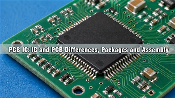
what is a motherboard? It is the main printed circuit board assembly in a computer. It distributes power, provides electrical paths between the processor, memory, storage and peripherals, and holds the sockets, connectors and control circuits that make those parts operate as one system. A motherboard does not perform every calculation itself; it provides the physical and electrical platform that lets each device exchange data reliably.
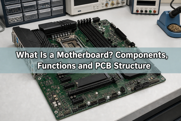
What Is a Motherboard and What Does It Do?
A motherboard, also called a mainboard, system board or mobo, is a populated PCB designed around a particular processor platform. It combines the bare circuit board with soldered devices, sockets, power converters, firmware memory, clocks and external interfaces. The CPU executes instructions, while the motherboard supplies the regulated power and communication routes the CPU needs to reach RAM, storage, graphics and I/O devices.
Its main functions are electrical rather than computational. The board converts incoming power into several lower-voltage rails, distributes clocks and reset signals, establishes high-speed links, stores startup firmware and exposes connectors that define how the computer can be expanded. A fault in any one of those paths can prevent booting even when the CPU and memory are undamaged.
What Components Are Found on a Motherboard?
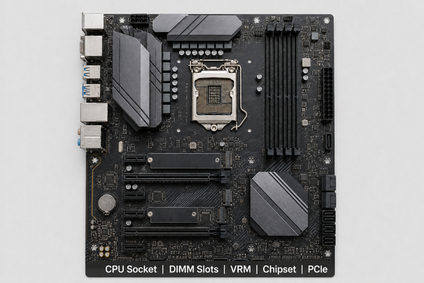
Component placement follows signal length, power delivery, thermal and mechanical constraints. The CPU socket is kept close to memory and VRM circuitry; high-speed connectors are positioned to control routing length; and rear I/O is aligned with the chassis opening. The following groups explain what each visible area contributes.
| Component | Primary role | Important design dependency |
|---|---|---|
| CPU socket | Mechanical and electrical interface for the processor | Socket generation, pin map, keep-out area and cooler load |
| DIMM slots | Connect system memory to the processor | Memory generation, topology, trace matching and slot count |
| Chipset | Manages platform I/O not connected directly to the CPU | PCIe lanes, USB, SATA and firmware support |
| VRM | Converts PSU input into stable low-voltage CPU and memory rails | Current capacity, transient response, copper area and cooling |
| PCIe and M.2 connectors | Connect graphics, storage and expansion devices | Lane allocation, generation, bifurcation and signal integrity |
| BIOS/UEFI flash | Stores platform initialization firmware | CPU support, recovery method and update path |
| Rear I/O and headers | Provide USB, network, audio, fan and front-panel connections | Port count, controller bandwidth and chassis layout |
How Does a Motherboard Work?
When the power button is pressed, standby power and control signals allow the PSU to start the main rails. The motherboard VRMs then generate the voltages required by the CPU, memory and chipset. After the rails and clocks stabilize, reset is released and the processor reads initialization code from the BIOS or UEFI flash device.
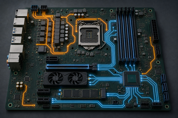
Firmware trains the memory interface, enumerates PCIe and storage devices, applies platform settings and selects a boot device. During normal operation, some high-bandwidth links run directly between the CPU and memory, graphics or primary storage. Other devices communicate through the chipset, which aggregates I/O before passing data to the processor. The board’s copper traces, reference planes, connectors and vias must preserve timing and signal quality across all of these paths.
What Is a Motherboard Chipset?
A motherboard chipset is the platform controller that expands the processor’s native interfaces. Modern CPUs often contain the memory controller and selected PCIe lanes, so the chipset no longer performs every function associated with older northbridge and southbridge designs. It commonly provides additional PCIe lanes, USB ports, SATA connections, networking interfaces and management functions.
Chipset choice affects available I/O and feature support, but the connector count printed on a product page does not reveal the complete topology. Several M.2 sockets, PCIe slots or high-speed USB ports may share uplink bandwidth or disable one another in particular configurations. A block diagram and lane-allocation table are therefore more informative than the number of physical connectors alone.
What Is a VRM on a Motherboard?
The voltage regulator module, or VRM, converts a 12 V input into the much lower voltage required by a processor or memory rail. A multiphase buck converter uses MOSFET power stages, inductors, capacitors and a controller to divide current among parallel phases. More phases can reduce current per phase, but controller quality, component ratings, switching behavior, copper area and thermal design matter more than a phase-count label by itself.
VRM layout is sensitive to loop inductance and heat concentration. Power stages and inductors are placed close to the CPU socket, while wide copper regions and internal planes carry high current. Thermal vias may spread heat into other layers or a backside area. Poor placement or insufficient copper can increase ripple, temperature and voltage droop during fast load changes.
What Are Motherboards Made Of?
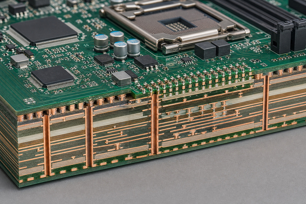
Most computer motherboards use a multilayer flame-retardant epoxy-glass laminate with copper conductors, commonly described as FR4. The finished assembly also contains solder mask, surface finish, legend ink, plated holes, solder alloys, connectors and semiconductor packages. Material selection is tied to layer count, impedance control, thermal load, lead-free assembly temperature and long-term dimensional stability.
A typical stack-up alternates signal layers with power or ground reference planes. The planes lower return-path impedance and help contain electromagnetic fields, while controlled dielectric thickness and copper geometry establish the impedance of PCIe, USB, memory and other high-speed traces. Best Technology’s documented multilayer FR4 PCB capability extends to 32 layers, although the practical stack-up, drill structure and conductor limits still require engineering review for the specific design.
How Are Motherboards Manufactured?
Production begins with a verified stack-up and fabrication data set. Inner copper layers are imaged and etched, inspected, aligned with prepreg and copper foil, and laminated under heat and pressure. Mechanical or laser drilling creates through-holes and microvias. Desmear and copper plating make the hole walls conductive before outer-layer imaging, solder-mask application, surface finishing and electrical test.
Dense processor, chipset and memory fan-out may require blind vias or sequential lamination. An HDI PCB structure can reduce via-pad size and routing congestion, but it adds process steps and demands strict registration control. The correct build depends on BGA pitch, escape routing, layer count, aspect ratio and reliability targets rather than on board size alone.
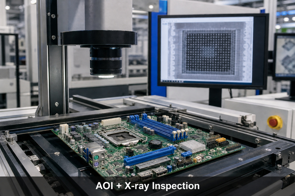
After bare-board fabrication, solder paste is printed, SMT components are placed and reflowed, and through-hole connectors are inserted and soldered. A motherboard combines fine-pitch ICs with large mechanical connectors, so paste volume, board support, thermal profiling and connector coplanarity need separate control. EBest Circuit (Best Technology) supports PCB assembly down to 01005 components and 0.25 mm BGA pitch, with 3D SPI, AOI and X-ray available for process verification.
What Are the Main Motherboard Form Factors?
Form factor defines the board outline, mounting-hole locations and general expansion layout. It must match the enclosure and power-supply arrangement. Dimensions alone are not enough; cooler clearance, card spacing, connector access and cable routing also determine whether a board fits the system.
| Form factor | Common dimensions | Typical design trade-off |
|---|---|---|
| ATX | 305 × 244 mm | More expansion slots and routing area, but requires a larger case |
| Micro-ATX | 244 × 244 mm | Smaller platform with fewer expansion positions |
| Mini-ITX | 170 × 170 mm | Compact system size with tight thermal and connector constraints |
| E-ATX | Often about 305 × 330 mm; vendor definitions vary | Additional area for memory, power and I/O, with chassis compatibility limits |
Embedded and industrial motherboards may use other outlines or fully custom dimensions. Their connector placement is often driven by the enclosure, backplane, cooling path and service access rather than by a retail desktop standard.
How Do Motherboard Interfaces and Expansion Paths Work?
PCIe uses point-to-point serial lanes that can be grouped as x1, x4, x8 or x16 links. A graphics slot may receive lanes directly from the CPU, while additional slots, controllers and M.2 sockets connect through the chipset. M.2 describes the connector and module format; the installed device may use PCIe/NVMe, SATA or another supported interface.
High-speed routing requires controlled impedance, continuous reference planes, short via stubs and careful connector transitions. Differential-pair spacing and length matching are set for the applicable interface, but return-path continuity is equally important. A slot can be mechanically x16 while carrying fewer electrical lanes, and populating one connector can reduce bandwidth or disable another if the design shares resources.
How Does a Motherboard Differ From a PCB?
A PCB is the general platform of insulating material, copper conductors, holes and surface finish used to connect electronic components. A motherboard is a specific type of PCBA: a fabricated PCB populated with the processor interface, memory connectors, power conversion, firmware, I/O and expansion circuitry needed to coordinate a computer system.
The distinction is similar to the difference between a road network and a particular city built on that network. A bare motherboard PCB cannot function until components are assembled and programmed. For a deeper board-level comparison, see circuit board vs motherboard; the earlier guide to how a motherboard works in modern computers provides additional system context.
How to Choose a Motherboard?
Start with non-negotiable compatibility, then evaluate expansion and electrical margin. Marketing tiers are less useful than a platform diagram, supported-component list and connector map.
- Match the CPU socket, chipset generation and BIOS version to the intended processor.
- Confirm the board outline, mounting points, rear-I/O opening, cooler clearance and expansion-card space.
- Verify the required memory generation, capacity, DIMM count and validated speed range.
- Map GPU, M.2, PCIe, SATA and high-speed USB connections to their available lanes and sharing rules.
- Check that the VRM and cooling design can sustain the processor’s real operating power, not only its nominal rating.
- Confirm the required network, display, audio, fan, debug, security and firmware-recovery features.
For a custom motherboard, the same sequence begins at architecture level: processor and memory interfaces define the stack-up and routing density; enclosure and connectors define the outline; power and thermal analysis define copper distribution; and assembly/test access affects component placement.
FAQ
Can a PC Run Without a Motherboard?
No. A conventional PC needs a motherboard or an equivalent integrated system board to distribute power and connect the processor, memory, storage and I/O. Individual devices may power up separately, but they cannot operate as a coordinated computer without the interconnect and control platform.
Is the CPU the Motherboard?
No. The CPU is a semiconductor package that executes instructions. It installs into or is soldered onto the motherboard, which supplies power and connections to the rest of the system.
What Does a Motherboard Look Like?
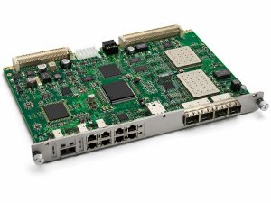
A desktop motherboard is usually a flat rectangular PCB with a prominent CPU socket, long DIMM and PCIe connectors, power connectors, several heatsinks and a rear-I/O cluster. Laptop and embedded boards often use irregular outlines and soldered processors to fit a specific enclosure.
Are Mainboard, System Board and Mobo the Same Thing?
They usually refer to the same primary circuit board. Mainboard and system board are common formal alternatives, while mobo is an informal abbreviation. In modular industrial equipment, however, a system may also contain backplanes, daughterboards or carrier boards with different roles.
Conclusion
Understanding what is a motherboard requires more than identifying sockets and ports. The board is a multilayer power and signal platform whose chipset topology, VRM, stack-up, vias, connectors, assembly process and inspection plan must work together. For custom motherboard PCB or PCBA support, EBest Circuit (Best Technology) can review the design against fabrication and assembly capabilities. Contact sales@bestpcbs.com with the project requirements.