A relay circuit board is a specialized printed circuit board designed to mount, connect, and control electromechanical or solid-state relays within electronic systems, enabling low-power signals to safely switch high-power loads. This article explores what a relay circuit board is, how it functions in PCB systems, common types, testing methods, soldering techniques, and practical applications.
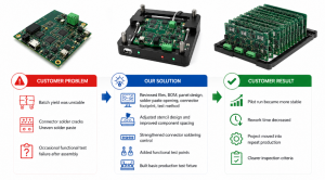
Are you facing difficulties with unreliable switching, damaged components, or confusing relay layouts on your boards?
- Unstable switching behavior causing intermittent device failures
- Overheating or burnt contacts due to incorrect relay selection
- Difficulty identifying relay pins and understanding what a relay looks like on a circuit board
- Poor soldering joints leading to loose connections or shorts
- Troubleshooting complexity when trying to test or replace a faulty relay on a circuit board
To address these pain points effectively, manufacturers must adopt reliable design and assembly practices that ensure performance and serviceability.
- Use properly rated power relay modules matched to load requirements
- Design clear silkscreen markings to identify relay pinouts and orientation
- Apply controlled soldering profiles to prevent thermal damage during assembly
- Provide accessible test points for easy testing of relays on a circuit board
- Offer modular relay sockets or through-hole designs to simplify removal and replacement
EBest Circuit (Best Technology) is a professional PCB and PCBA manufacturer based in China, specializing in high-reliability printed circuit board relays, power relay modules, and custom relay board circuits. With advanced SMT lines, rigorous quality control, and engineering support, we deliver robust solutions for industrial automation, automotive, and smart lighting systems. For inquiries, pls feel free to contact us at sales@bestpcbs.com.
What Is a Relay Circuit Board and How Does It Work?
A relay circuit board integrates one or more relays into a PCB layout to control electrical loads safely and efficiently. It acts as an interface between low-voltage control circuits (like microcontrollers) and high-voltage/high-current devices (such as motors, lights, or HVAC systems).
How It Works in PCB Systems:
- Control Signal Input – A low-voltage signal (e.g., 3.3V or 5V from an MCU) activates the relay coil.
- Electromagnetic Induction – The energized coil creates a magnetic field that pulls the armature.
- Contact Switching – Mechanical movement closes or opens the high-power contacts.
- Load Control – The switched contacts complete or break the circuit powering the external device.
- Isolation – Electrical isolation between control and load sides prevents back EMF damage.
| Component | Function |
|---|---|
| Relay Coil | Converts electrical signal into magnetic force |
| Contacts (NO/NC/COM) | Switch high-current paths |
| Diode (Flyback) | Suppresses voltage spikes |
| PCB Traces | Route signals and power safely |
This architecture allows a 12V relay circuit board or 8 channel relay board circuit to manage multiple loads independently while protecting sensitive logic components.
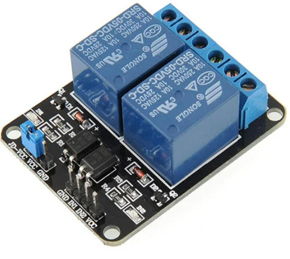
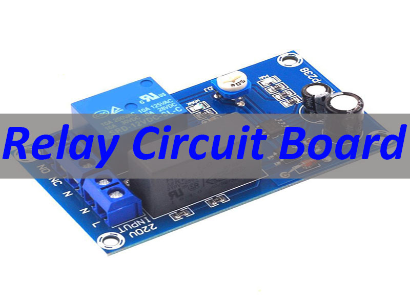
What Does a Relay Look Like on a Circuit Board?
On a circuit board relay, you’ll typically see a rectangular plastic housing with visible metal terminals or pins. Common forms include:
- Through-hole relays: Large, vertically mounted with clearly labeled pins (Coil, NO, NC, COM)
- Surface-mount relays: Smaller, flat packages suitable for compact PCB relay designs
- Socketed relays: Plug-in types for easy removal and replacement
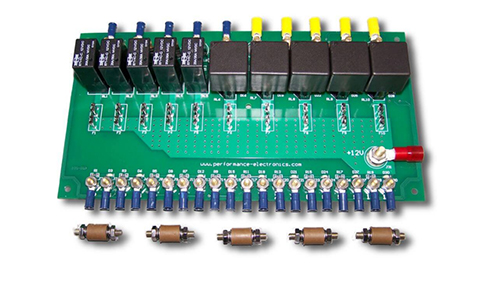
- Multi-channel modules: Arrays like 16 channel relay board circuit diagrams showing grouped relays
Silkscreen labels often indicate pin functions, making it easier to identify and test a relay on a circuit board.
What Types of Relays Are Used on PCB Relay Boards?
Different applications require different relay technologies. Below are common types used in relay board circuits:
| Relay Type | Key Features | Typical Use Case |
|---|---|---|
| Electromechanical Relay (EMR) | Mechanical contacts, audible click | General-purpose switching, lighting relay |
| Solid-State Relay (SSR) | No moving parts, silent operation | High-speed switching, industrial controls |
| Reed Relay | Fast switching, small size | Test equipment, signal routing |
| Latching Relay | Maintains state without continuous power | Energy-saving systems |
| Automotive Relay | High vibration resistance | 2014 Honda Accord relay circuit board, 2016 Civic relay board |
Choosing the right type ensures compatibility with your power relay requirements and environmental conditions.
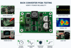
How to Test a Relay on a Circuit Board (Step-by-Step Guide)
Testing a circuit board relay helps diagnose faults before replacing components. Follow these steps:
- Visual Inspection – Look for burnt marks, cracked housings, or lifted pads.
- Check Coil Resistance – Use a multimeter; typical values range from 50Ω to 500Ω.
- Test Contact Continuity – Measure between COM and NO/NC terminals in energized/de-energized states.
- Apply Control Voltage – Power the coil and listen for a click (EMR) or verify LED indicator (SSR).
- Verify Load Switching – Confirm the connected device turns on/off correctly.
These steps apply whether you’re troubleshooting a Chevy Express circuit board relay or a custom 2 channel relay board circuit diagram.
How to Solder and Replace a Relay on a Circuit Board Safely
Proper technique prevents damage during installation or repair.
Soldering Tips:
- Preheat the board to reduce thermal shock
- Use rosin-core solder and avoid excess heat
- Align pins correctly before fixing in place
- For how to solder a relay on a circuit board, ensure full pin penetration and clean joints
Replacement Steps:
- Desolder old relay using wick or vacuum pump
- Clean pads thoroughly
- Insert new relay matching orientation
- Solder all pins securely
- Test functionality before final assembly
This process works for replacing a relay on a circuit board in both consumer and automotive applications.
How to Remove a Relay from a Circuit Board Without Damage
To remove a relay from a circuit board safely:
- Heat each pin evenly using a soldering iron
- Use desoldering braid or suction tool to clear holes
- Gently lift the relay once all solder is removed
- Avoid pulling forcefully to prevent pad delamination
- Inspect pads for damage before installing a new unit
This method minimizes risk when performing relay board circuit repairs.
What Are Common Relay Circuit Board Applications?
Relay circuit boards are widely used across industries:
- Automotive: Engine control, lighting, and accessory management (2015 Honda Accord relay circuit board)
- Home Automation: Smart lighting, garage doors, security systems
- Industrial Equipment: Motor starters, PLC interfaces
- HVAC Systems: Compressor and fan control
- Consumer Electronics: Appliances, power strips with remote control
From 4 channel relay board circuits to complex 8 channel relay board circuit diagram PDFs, these boards enable safe high-power control.
How to Choose the Right Relay Circuit Board for Your Project?
Selecting the correct relay for circuit board integration depends on several factors:
- Voltage & Current Rating – Match load requirements (e.g., 12V, 24V, 120V AC)
- Number of Channels – Single vs multi-channel (16 channel relay board circuit diagram)
- Form Factor – Through-hole vs SMT based on space constraints
- Switching Speed – EMR vs SSR depending on frequency
- Environmental Conditions – Temperature, humidity, vibration resistance
Consulting with an experienced PCBA partner ensures optimal relay board circuit design.
To sum up, a relay circuit board is a critical component in modern electronics, allowing low-voltage control systems to safely manage high-power devices through isolated switching. This guide covered what a relay circuit board is, how it works in PCB systems, identification, testing, soldering, removal, and application selection.
EBest Circuit (Best Technology) provides expert PCBA services including printed circuit board relays, power relay modules, and custom relay board circuits for diverse industries. Our engineering team ensures reliable performance and compliance with international standards. For professional support and manufacturing, pls feel free to reach out to us at sales@bestpcbs.com.
FAQs About Relay Circuit Board
Q: What does a relay look like on a circuit board?
A: Usually a rectangular component with visible pins, often labeled with coil and contact terminals.
Q: Can I test a relay without removing it?
A: Yes, using a multimeter to check coil resistance and contact continuity.
Q: Is soldering a relay difficult?
A: Not if proper tools and techniques are used—avoid overheating.
Q: Why use a relay instead of a transistor?
A: Relays provide galvanic isolation and handle higher currents.
Q: Where can I get a custom relay circuit board made?
A: Contact EBest Circuit at sales@bestpcbs.com for tailored solutions.