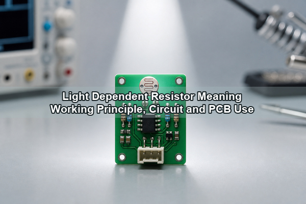
Light dependent resistor meaning refers to a passive light-sensitive component whose resistance changes with incident illumination. Also called an LDR, photoresistor, photocell, or photoconductive cell, it normally has high resistance in darkness and lower resistance under brighter light. This article explains how the device works, how to select and connect one, when another photosensor is better, and what matters when the circuit moves from a schematic to a manufactured PCB assembly.
What Are Light Dependent Resistors?
Light dependent resistors are passive components whose resistance varies according to the light reaching their photosensitive surface. A light dependent resistor is also called a photoresistor because it does not generate a powered output by itself; a circuit reads the resistance change through a voltage divider, comparator, operational amplifier, or microcontroller analog input.
The abbreviation LDR should not be confused with the imaging term low dynamic range. In component and PCB discussions, LDR means light dependent resistor. The part is commonly identified by a serpentine photosensitive track on a round or rectangular face with two leads or terminals.
How Does a Photoresistor Work?
A photoresistor works through photoconductivity. When photons with sufficient energy reach the semiconductor material, they increase the number of available charge carriers. Conductivity rises, so electrical resistance falls. In darkness, fewer carriers are available and resistance rises again.
The response is nonlinear. Datasheets may express it with a resistance-versus-illumination curve or with a gamma value in an approximate relationship such as R = A x E-gamma, where E is illuminance. Do not assume that doubling the lux level halves the resistance. Part tolerance, temperature, spectral content, previous illumination, and recovery time can all change the measured value.
Does Photoresistor Resistance Increase with Light?
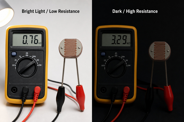
LDR resistance decreases as illumination increases and increases as illumination decreases. This inverse response is the key behavior used in automatic lighting, beam interruption, display dimming, and ambient-light detection.
Resistance values are meaningful only when the measurement condition is defined. A supplier may specify light resistance at 10 lux, 100 lux, or another level using a particular color temperature or test source. Dark resistance may also be measured after a stated dark-adaptation time. Compare parts at the same illumination, spectrum, temperature, and timing rather than comparing isolated resistance numbers.
What Does the Light Dependent Resistor Symbol Look Like?
The LDR circuit symbol uses a resistor symbol with two arrows pointing toward it to represent incoming light. Some drawing standards enclose the resistor in a circle, while resistor geometry may be rectangular or zigzag depending on the schematic convention. The arrows point toward the resistor; outward arrows normally indicate a light-emitting device.
An LDR is normally non-polarized, so its two terminals can be reversed electrically. The PCB footprint still needs the correct body diameter, lead pitch, lead diameter, component height, and keepout. Use the BOM manufacturer part number and datasheet footprint instead of relying only on a generic LDR schematic symbol.
Which Specifications Matter When Selecting an LDR?
The most useful LDR specifications describe the operating point, tolerance, optical response, electrical limits, and physical package. Select the part around the actual threshold or measurement range rather than choosing only by dark resistance.
| Datasheet Item | What It Controls | Engineering Check |
|---|---|---|
| Light resistance | Resistance at a stated illuminance | Match the supplier’s lux, spectrum, and test timing to the application. |
| Dark resistance | Leakage-like resistance after darkness | Confirm dark-adaptation time and acceptable off-state current. |
| Gamma or sensitivity curve | Nonlinear change across illumination | Use the curve when setting thresholds or estimating ADC range. |
| Spectral response | Wavelengths the device detects | Check performance under sunlight, LEDs, fluorescent lamps, or IR sources. |
| Rise and decay time | Speed from dark to light and light to dark | Avoid LDRs when fast pulse detection or precise timing is required. |
| Maximum voltage and power | Electrical stress limit | Verify the worst-case divider voltage, current, and self-heating. |
| Temperature coefficient | Resistance drift with temperature | Validate threshold margin across the product temperature range. |
| Package and lead pitch | PCB and enclosure fit | Confirm body diameter, height, pitch, optical opening, and soldering method. |
| Compliance status | Market and material restrictions | Check the exact part’s RoHS status and destination-market requirements. |
Many common LDRs use cadmium sulfide. Cadmium restrictions and exemptions differ by product category and market, so a generic component name is not enough for compliance approval. Request a current declaration for the exact manufacturer part number, and evaluate a compliant alternative when the product has no applicable exemption.
How Does a Light Dependent Resistor Circuit Work?
An LDR is commonly paired with a fixed resistor to convert resistance into a voltage. If the LDR connects from VCC to the output node and the fixed resistor connects from the node to ground, the output is VCC x Rfixed / (RLDR + Rfixed). More light lowers RLDR, so the output voltage rises. Swapping the two components makes the output fall as light increases.
Choose the fixed resistor near the expected LDR resistance at the desired switching illuminance to obtain useful sensitivity around that point. For a digital on/off function, feed the divider into a comparator and add hysteresis so small light fluctuations do not cause rapid switching. For an ADC input, check source impedance, sampling time, reference voltage, noise, and the voltage range across minimum and maximum illumination.
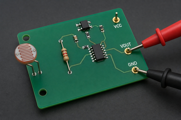
A prototype should be measured under the real optical path. Enclosure color, window transmission, sensor angle, nearby LEDs, daylight direction, and internal reflections can move the switching point even when the schematic values are unchanged. The custom PCB design for sensors guide covers related signal, power, and test-access decisions.
How Does an LDR Compare with a Photodiode and Phototransistor?
An LDR is suitable for low-cost, relatively slow light-level detection, while photodiodes and phototransistors are better when speed, repeatability, or defined spectral performance matters. A digital ambient-light sensor is often preferable when the system needs a calibrated lux output or direct digital communication.
| Device | Output Behavior | Strength | Main Limitation | Typical Choice |
|---|---|---|---|---|
| LDR / photoresistor | Resistance changes with light | Simple divider, broad sensing area, low circuit complexity | Nonlinear, relatively slow, temperature and history dependent | Dusk switches, beam presence, approximate ambient-light control |
| Photodiode | Light-dependent current | Fast response and good linearity with proper amplifier design | Often needs a transimpedance amplifier | Optical measurement, pulse detection, communication |
| Phototransistor | Amplified light-dependent collector current | Higher sensitivity than a photodiode in simple circuits | Slower and less linear than a photodiode | Object detection, optocouplers, light switches |
| Ambient-light sensor IC | Analog or digital calibrated output | Defined range, compensation, and sometimes lux conversion | Higher cost and more integration requirements | Displays, portable products, controlled brightness systems |
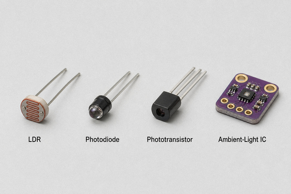
Do not replace one sensor type with another based only on package size. The bias circuit, output polarity, gain, bandwidth, spectral response, temperature behavior, and firmware thresholds may all need redesign. For infrared applications, start with the IR sensor PCB design guide because an LDR intended for visible light may not match the target wavelength.
What Can an LDR Be Used For?
LDRs are used where the circuit needs an economical indication of light level and does not require a fast, linear optical measurement. Common applications include dusk-to-dawn lighting, night lights, display dimming, beam interruption alarms, camera exposure support, toys, teaching boards, greenhouse controls, and light-controlled relays.
- Use an LDR when response time can be slow, calibration can be unit-specific, and a voltage divider provides enough information.
- Use a photodiode for fast optical signals, quantitative measurement, or low-light detection with an amplifier.
- Use a phototransistor when a simple circuit needs more sensitivity than a photodiode.
- Use an ambient-light IC when firmware needs a repeatable calibrated value, temperature compensation, or a digital interface.
An LDR may be unnecessary if the product already contains a camera, color sensor, or ambient-light IC that can supply the required information. It may also be unsuitable for safety-critical timing, precise lux measurement, or products where the selected CdS part cannot meet compliance requirements.
What PCB Layout and Assembly Rules Matter for LDR Circuits?
The LDR must be positioned for a controlled optical path, not simply where routing is convenient. Place the photosensitive face under the intended window or opening, define component height and orientation, and keep enclosure ribs, labels, cables, and tall components from shading it.
- Keep indicator LEDs and backlights from creating unwanted optical feedback unless they are part of the sensing design.
- Separate the LDR from hot regulators, power resistors, and other heat sources that can shift resistance.
- Provide a solder-mask and silkscreen keepout around the optical face; do not let coatings cover the active surface.
- Confirm whether conformal coating, potting, ultrasonic cleaning, or wash chemistry is allowed by the component datasheet.
- For through-hole LDRs, define lead forming, seating height, polarity note if used for orientation only, and wave/selective/hand-solder limits.
- Add an accessible test point at the divider output and, when useful, at each side of the sensor.
- Use a ground reference and filtering appropriate to the ADC or comparator; long high-impedance traces can pick up noise.
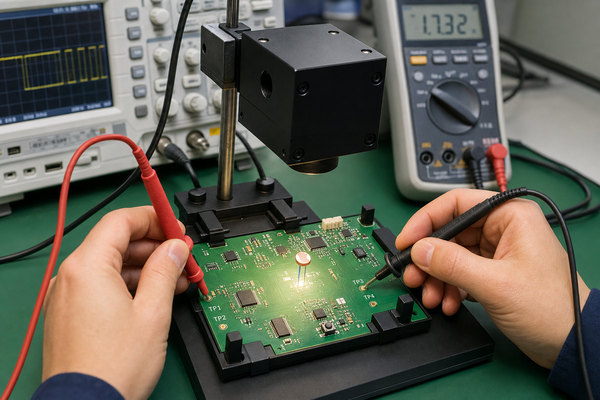
If the design mixes through-hole sensors with SMT components, document the assembly sequence and thermal limits. The surface mount electronic components guide and through-hole PCB design checklist provide additional footprint and process guidance.
How Do You Test an LDR on a PCB?
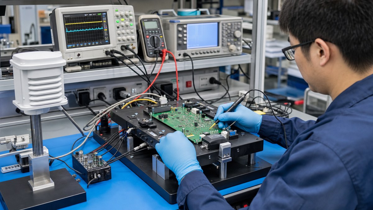
Test an LDR by controlling illumination and checking either its resistance or the circuit output at defined light levels. An uncovered bench measurement under changing room light is not a repeatable production test.
- Incoming check: verify the manufacturer part number, package, lead pitch, compliance documents, and representative light/dark response.
- Unpowered resistance check: isolate the part from parallel circuit paths or account for them before interpreting a multimeter reading.
- Powered functional check: apply defined illumination at the specified distance and angle, then measure divider voltage or comparator state.
- Threshold margin: test on both sides of the switching point and across the intended temperature range.
- Recovery test: allow the specified dark adaptation and response time before recording values.
- System check: repeat the test with the final enclosure, light pipe, window, and nearby emitters installed.
For volume production, a fixture should control source type, brightness, distance, angle, dwell time, and ambient light. Store limits for the assembled output rather than expecting every LDR to produce an identical resistance. Functional limits should include component tolerance and the fixed resistor, supply, ADC, comparator, and optical-mechanical tolerances.
Why Does an LDR Circuit Flicker Near the Switching Threshold?
An LDR-controlled output can switch repeatedly when the measured voltage sits close to one threshold. Small changes in ambient light, electrical noise, supply variation, shadows, or light from the controlled lamp can move the divider voltage back and forth across that point.
- Add hysteresis: use a Schmitt-trigger comparator or positive feedback so the turn-on and turn-off thresholds are different. A separation of roughly 10% to 20% of the target threshold is a practical starting point for slow ambient-light controls, then adjust it from measured behavior.
- Filter short changes: add an RC filter at the divider output. Time constants from about 100 ms to 1 s are common for room-light or dusk-to-dawn functions, but the value must remain shorter than the required response time.
- Debounce in firmware: average several ADC samples or require the signal to remain beyond the threshold for a defined interval before changing state.
- Stop optical feedback: prevent indicator LEDs, displays, or the controlled lamp from illuminating the LDR unless that feedback is intentional.
- Verify both transitions: increase and decrease illumination slowly while recording the switching points, then repeat the test with the final enclosure installed.
Filtering and hysteresis solve different problems. Filtering suppresses brief changes, while hysteresis creates stable decision margins. Many reliable LDR circuits use both, especially when the sensor controls a relay, lamp, or display whose own light can affect the measurement.
FAQ About Light Dependent Resistors
1. What does LDR stand for?
LDR stands for light dependent resistor. It is another name for a photoresistor, a passive component whose resistance changes with incident light.
2. What is an example of an LDR?
A common example is a CdS photoresistor used in a dusk-to-dawn light. The LDR and a fixed resistor form a divider whose output changes when ambient light falls below the switching threshold.
3. Does an LDR have polarity?
Most two-terminal LDRs are non-polarized and can be connected in either direction. Mechanical orientation still matters because the photosensitive face must align with the light source or enclosure opening.
4. Is an LDR the same as a light sensor?
An LDR is one type of light sensor. Photodiodes, phototransistors, and ambient-light sensor ICs also detect light but produce different outputs and have different speed, linearity, sensitivity, and circuit requirements.
5. Can an LDR measure lux accurately?
An LDR can indicate relative light level, but it is usually not the best choice for accurate lux measurement because its response is nonlinear and affected by tolerance, temperature, spectrum, and history. Use a calibrated ambient-light sensor or a characterized photodiode system when accuracy matters.
6. Why does an LDR circuit flicker near the threshold?
Small light changes, noise, supply variation, or optical feedback can move the divider repeatedly across one threshold. Add comparator hysteresis, filtering, firmware averaging, or a wider decision band, then verify the result under the final enclosure and light source.
7. What are the disadvantages of using an LDR?
An LDR is nonlinear, relatively slow, sensitive to temperature and light spectrum, and subject to wide part tolerance and recovery effects. Cadmium-based parts may also face market-specific material restrictions. Use a photodiode or ambient-light sensor IC when speed, calibration, or repeatability is more important than circuit simplicity.
8. Can an LDR be covered with conformal coating?
Do not coat the active surface unless the component manufacturer and optical design explicitly allow it. A coating can change transmission, collect contamination, or permanently alter sensitivity. Use a keepout or an approved optical window when protection is required.
Conclusion
Light dependent resistor meaning is straightforward: an LDR is a passive photoresistor whose resistance falls as light increases. A reliable product still requires more than that definition. Select the operating curve and package from the datasheet, design the divider around the target illumination, control the optical path, account for temperature and response time, and define a repeatable test with the final enclosure.
For technical support with an LDR sensor PCB or mixed-technology PCBA, contact EBest Circuit (Best Technology) at sales@bestpcbs.com.