Conformal coating inspection PCB assembly planning must begin before material is applied. A glossy board is not automatically a protected board: the coating can miss a critical edge, bridge into a connector, trap contamination, remain uncured, or hide damage that existed before coating.
This guide gives buyers and engineers a release path from incoming assembly condition through masking, application, cure, inspection, test, repair, and traceable acceptance. Exact material, method, thickness, cure, and equipment must be confirmed for the project rather than assumed from a general quote.
Can your supplier show where coating is required, where it is forbidden, and what evidence releases each assembly?
If the answer is only “visual inspection,” the RFQ is missing the drawing boundaries, defect criteria, cure evidence, test plan, and repair rules needed to compare suppliers.
EBest Circuit can review Gerber or ODB++, BOM, assembly drawings, coating and masking requirements, component constraints, quantity, inspection evidence, test requirements, and delivery target before confirming project-specific support.
The coating material, thickness, application method, cure process, inspection equipment, and acceptance standard are not universal capabilities and must be agreed for the actual build.
Define the Coating and Inspection Requirement Before Production
Release a controlled requirement that identifies the coating material or approved family, coverage zones, keep-outs, thickness basis when applicable, cure condition, appearance limits, inspection method, and acceptance authority. Link it to the correct assembly revision and product environment.
A purchase order line that says “apply conformal coating” leaves the supplier to guess which surfaces, components, edges, vias, connectors, test points, and hardware need protection or exclusion. That uncertainty becomes a quote gap and a production dispute.
Inspect PCB Assemblies Before Coating Starts
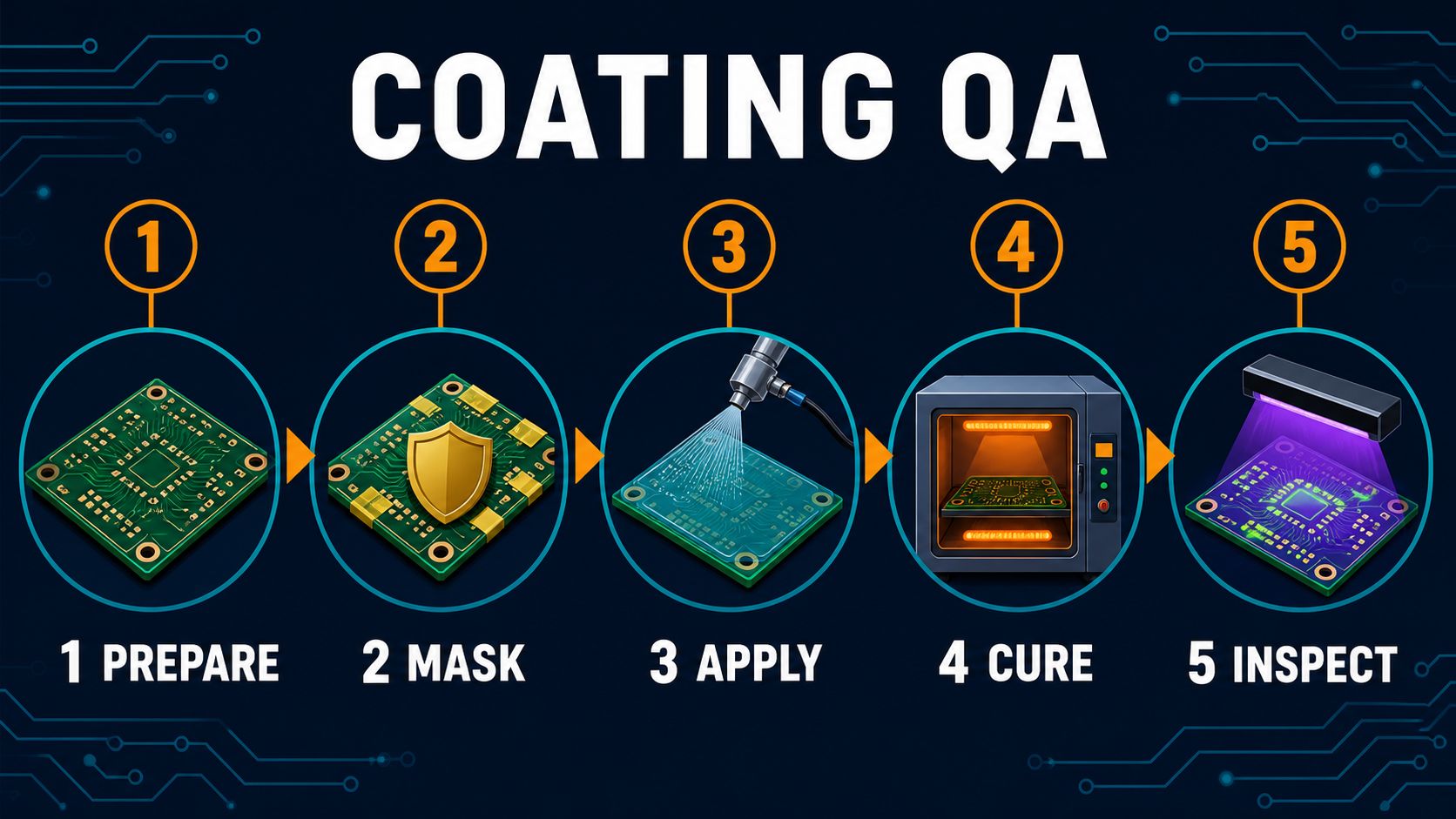
Coating should not become a cover for existing defects or contamination. Verify assembly revision, cleanliness requirement, component presence and orientation, solder condition, damage, markings, connectors, test status, and any customer hold points before masking or coating.
Record pre-coat acceptance when later investigation would be difficult. The broader PCBA manufacturing guide shows why inspection and test gates must be planned as one route rather than added at shipment.
Turn the Masking Drawing Into an Inspectable Boundary
Mark every keep-out with a clear datum, dimension, component reference, or controlled image. Common exclusions may include connector contacts, mating surfaces, switches, sockets, grounding points, test pads, programming contacts, heat-transfer interfaces, optical windows, labels, or adjustment features.
Define allowable edge variation and what counts as coating intrusion. A vague red cloud on a screenshot is hard to measure and harder to reproduce after a revision change.
Control Coating Preparation, Application, and Cure Records
Inspection begins with process identity. Record the material lot and expiry where required, mix or preparation status, viscosity or environmental checks when specified, application method, program or operator, time, cure route, and any hold between steps.
Do not copy generic temperature, time, or humidity values into the RFQ. Use the selected material data, product limitations, customer requirements, and an approved work instruction.
Check Coverage Without Hiding Keep-Out Violations
Inspect both required coverage and forbidden coverage. Confirm the board side, component bodies, leads, solder joints, edges, corners, and local zones named by the drawing, while checking that coating has not entered contacts, test points, fastener surfaces, or other keep-outs.
Use a route that prevents inspectors from focusing only on bright, easy-to-see surfaces. Coverage must be evaluated against the released map, not against the appearance of a nearby “good” board.
Separate Cosmetic Variation From Functional Defects
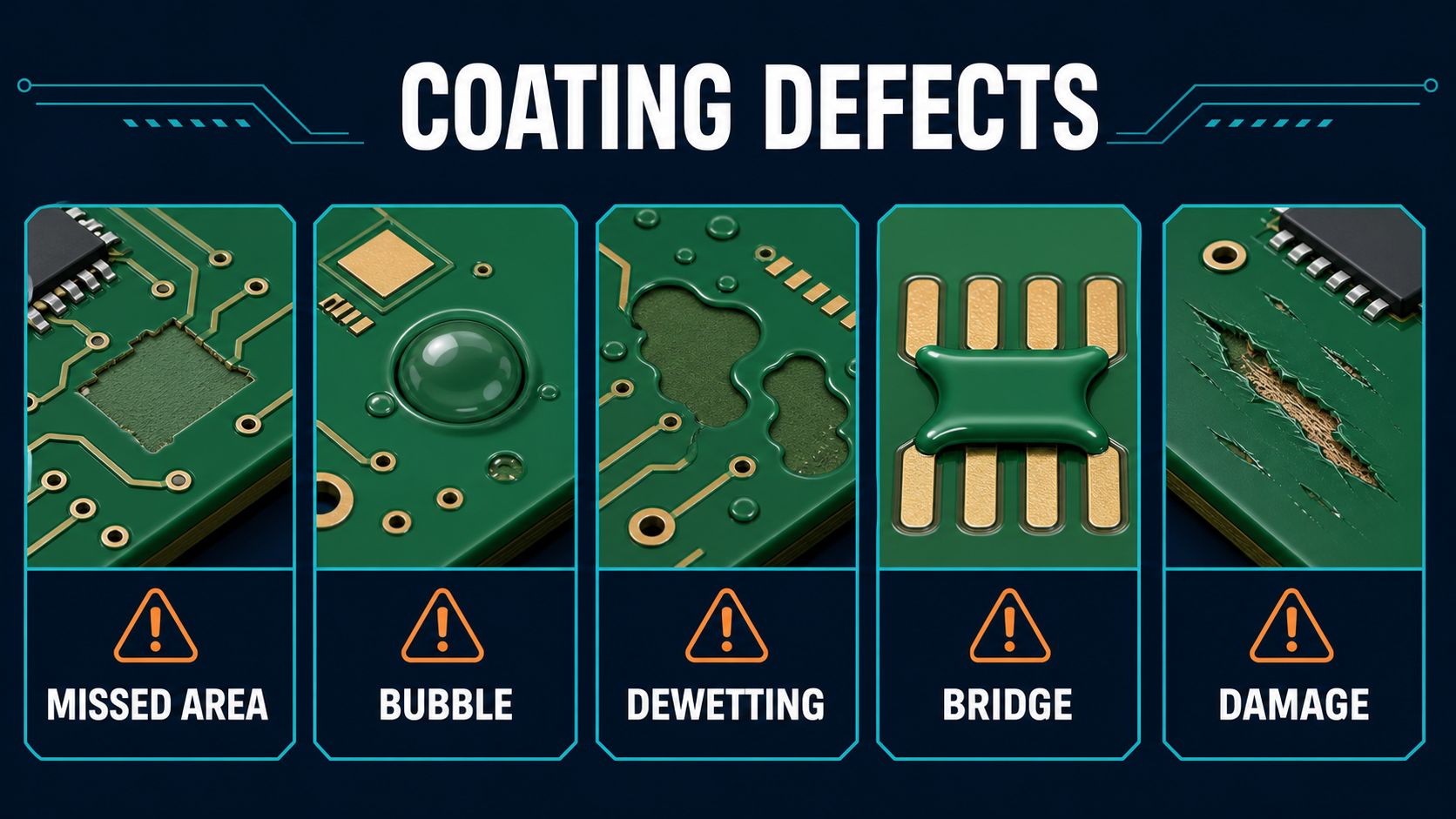
Define which conditions affect protection, electrical behavior, mechanical fit, cure, adhesion, or future service. Typical review categories include missed areas, thin or heavy zones, bubbles, voids, dewetting, fisheyes, runs, pooling, cracks, contamination, fibers, bridging, overspray, lifting, discoloration, and damage.
Names alone are insufficient. Specify location, size or extent where needed, risk, disposition, and whether the condition can be repaired. Do not reject harmless variation or accept a functional keep-out violation because both are called “appearance.”
Use UV, White Light, and Magnification for Different Questions
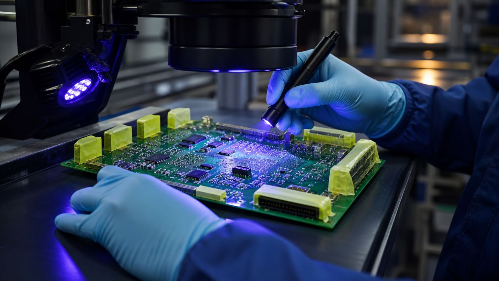
No single viewing condition answers every inspection question. UV response can help reveal coverage for compatible materials; white light shows color, contamination, pooling, masking residue, and physical damage; magnification helps evaluate edges, leads, bubbles, cracks, and small intrusions.
Inspection performance depends on the selected coating and board. Define lighting, viewing access, magnification, reference samples, and evidence capture where the product risk requires them. The AOI quality guide explains why automated optical results also depend on detectable features and programmed criteria.
Treat Thickness and Cure as Specification-Driven Evidence
Measure thickness only with a method, location, timing, and acceptance range suitable for the selected coating and assembly. A wet-film reading, dry-film result, coupon, witness panel, or other method answers a different question; the RFQ must state which evidence is required.
Cure verification may rely on approved time and environment records plus inspection or test defined by the material and customer. “Dry to the touch” is not a universal release criterion.
Inspect Under Components, Leads, Edges, and Shadowed Areas
Plan access for areas that are difficult to see after application. Tall components, close stand-offs, lead rows, connectors, board edges, heat sinks, mechanical hardware, and dense local geometry can create shadows, capillary flow, pooling, or incomplete penetration.
Decide whether these areas require direct viewing, angled optics, a witness feature, a process validation, or a documented exception. Do not promise complete under-component coverage unless the design, material, method, and acceptance approach support it.
Test the Assembly After Coating Without Damaging the Evidence
Repeat the electrical or functional checks needed to show that coating, masking removal, cure, and handling did not change performance. Define accessible test interfaces before coating and protect them according to the masking plan.
State limits, fixture, program, data retention, retest, and failure disposition. The PCB assembly testing services guide helps buyers distinguish structural inspection from electrical proof.
Control Repair, Touch-Up, and Reinspection
A coating repair is a controlled process, not an invisible cosmetic edit. Authorize the defect, protect the assembly, remove or prepare material as approved, correct the cause, reapply the selected coating, cure it, reinspect the full affected zone, and repeat required testing.
Record repair count, location, material, operator, date, inspection, and disposition when traceability is required. Use the PCB assembly rework process to structure authorization and release evidence.
Make the coating drawing, masking map, inspection evidence, and test plan agree before the first build.
Send Gerber or ODB++, BOM, assembly drawings, coating specification, keep-out map, component restrictions, quantity, inspection criteria, test requirements, traceability, and target date.
Coating | Masking | Cure | Coverage | Test | Evidence | Quantity
Link Coating Evidence to the Correct Lot or Serial Number
Traceability should connect the assembly revision, coating material lot, work instruction, process date, inspection result, repair, test, and shipment identity at the level the customer requires. Preserve both first-pass and final acceptance when failures or repairs matter.
The PCB assembly traceability requirements guide helps define the join keys and retention scope before quoting.
Compare Conformal Coating Quotes by Included Evidence
Normalize material sourcing, cleaning or preparation, masking labor and tooling, application method, cure, inspection, thickness evidence if specified, test, traceability, samples, repair, packaging, NRE, and exclusions. A low unit price may omit masking complexity or post-coat test.
Ask whether the quote assumes customer-supplied material, validated drawings, reusable masks, witness coupons, special handling, or a fixed batch size. Compare the deliverable evidence, not only the coating name.
Send an RFQ Package That Defines Coating Release
Provide one revision-controlled package. Include PCB and assembly data, BOM and AVL, drawings, selected coating or approval route, environmental objective, keep-out map, component restrictions, cleaning requirement, application and cure constraints, coverage and defect criteria, thickness evidence if required, inspection method, test, traceability, quantity, packaging, and schedule.
Ask the supplier to mark every assumption and exclusion. EBest Circuit will review the submitted package and confirm what can be supported for the specific project.
Conformal Coating Inspection FAQ
What should be inspected before conformal coating?
Verify revision, cleanliness requirement, assembly defects, component condition, markings, connectors, test status, and any customer hold point before masking.
Does UV light prove coating thickness?
No. UV response can help reveal coverage for compatible materials, but thickness needs a specified measurement method and location.
Which areas are usually masked?
The drawing may exclude contacts, connectors, switches, sockets, test points, grounding or heat-transfer surfaces, labels, optics, and adjustment features.
Are bubbles always rejectable?
Not by name alone. Acceptance depends on size, location, extent, coating specification, product risk, and the released defect criteria.
How do inspectors find missed coating?
They use the approved coverage map with suitable white light, UV when compatible, magnification, viewing angles, and evidence capture.
Should assemblies be tested after coating?
Use the product-specific electrical or functional checks needed to prove that coating, cure, masking removal, and handling did not change performance.
Can coating be repaired?
Yes when an approved repair route defines preparation, material, cure, reinspection, test, and traceability; do not treat touch-up as an undocumented cosmetic action.
How is conformal coating thickness specified?
Define the selected material, required range, measurement method, location, timing, coupon or witness approach, and disposition rules.
Does EBest use a default coating material and inspection machine?
No default should be assumed. Submit the project requirements so material, application, cure, inspection, and test scope can be reviewed and confirmed.
What files are needed for a conformal coating quote?
Send PCB and assembly data, BOM, drawings, coating and masking requirements, component constraints, quantity, inspection evidence, test, traceability, packaging, and delivery target.
Convert “apply coating” into a release-ready manufacturing package.
Email Gerber or ODB++, BOM, coating and masking drawings, selected material or approval route, cure constraints, defect criteria, inspection evidence, test plan, quantity, packaging, and delivery target. EBest Circuit will confirm project-specific support.
Files | BOM | Masking | Cure | Inspect | Test | Release