





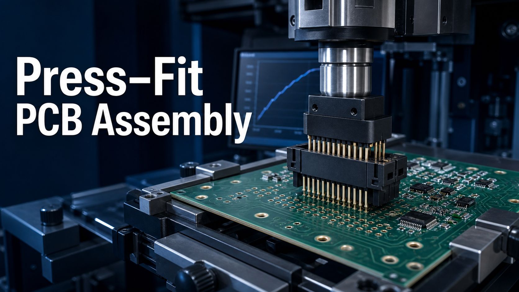
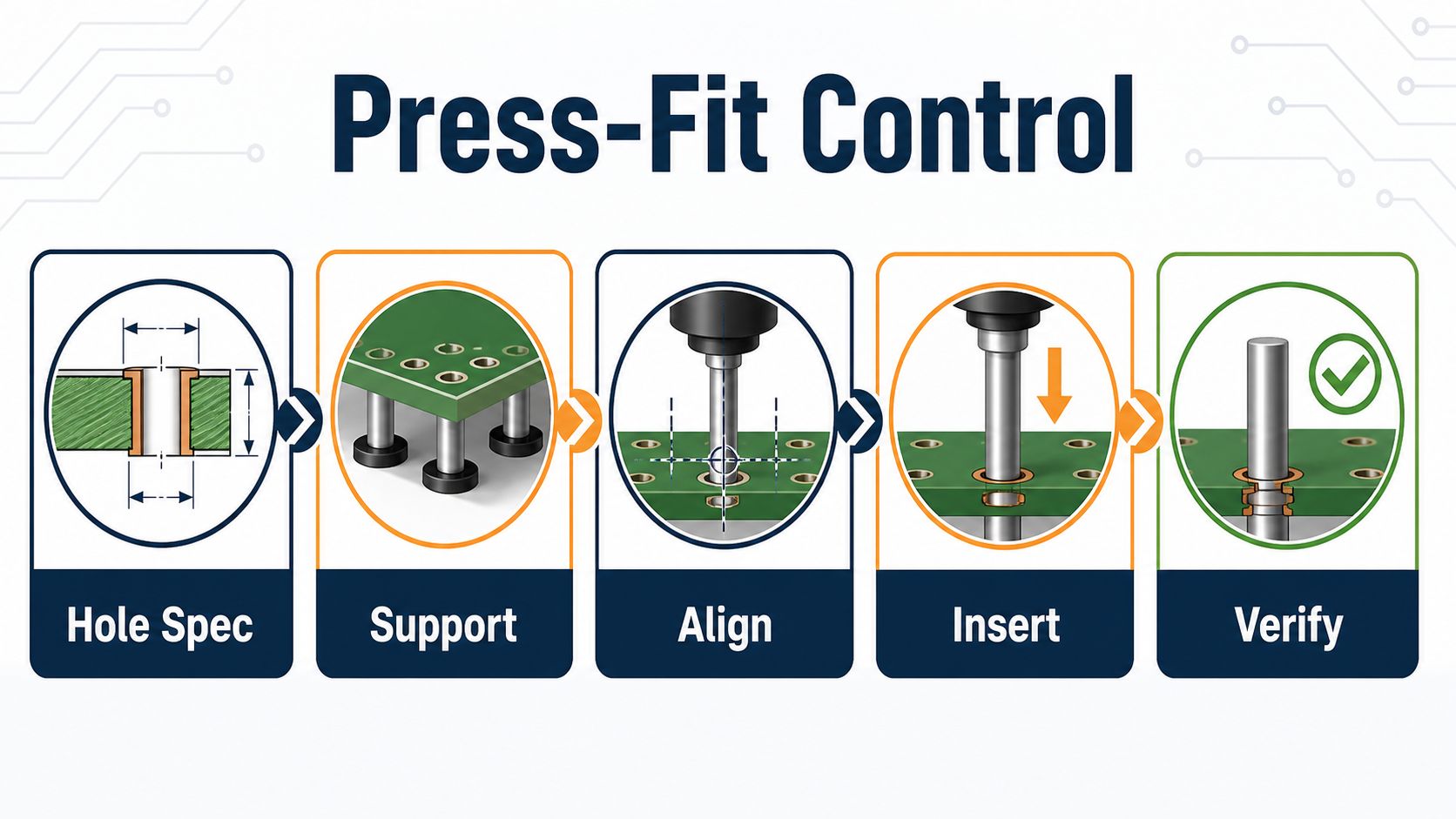
A press fit PCB assembly process creates an electrical and mechanical connection by inserting compliant pins into controlled plated through holes without soldering the joint. Success depends on matching the connector specification to the finished-hole geometry, supporting the board, aligning every pin, monitoring insertion, and verifying the finished assembly.
This guide helps engineers and buyers prepare a press-fit RFQ without assuming that a generic drill size, connector name, or press setting will work for every board.
Can the supplier prove that the pin, finished hole, board support, and insertion cycle form one controlled process?
A connector may look seated while one pin is folded, one hole is damaged, or the board has flexed. Define input specifications and release evidence before production.
EBest Circuit can review the customer’s connector data, PCB files, hole requirements, mechanical model, insertion specification, quantity, and acceptance plan before confirming project-specific support.
No EBest finished-hole tolerance, pin compatibility, force limit, press equipment, or yield should be assumed without that review.
What the Press-Fit PCB Assembly Process Must Control
The process must protect hole integrity, pin geometry, board structure, seating, and electrical performance. Control the released connector, plated-hole requirement, PCB revision, fixture, orientation, insertion sequence, force or displacement evidence where required, inspection, test, and traceability.
Press-fit is not simply “push until seated.” The connection relies on elastic interaction between the compliant section and the plated hole, so both component and PCB data are manufacturing inputs.
Confirm the Connector and Compliant-Pin Specification First
Use the exact manufacturer part number and current application specification. Record pin style, approved hole range, board thickness or engagement constraints, insertion tool, seating reference, force guidance, repair rules, and any keep-out or support requirements.
Do not substitute a visually similar connector or infer compatibility from nominal pitch. Approved alternates need engineering review and revision control.
Translate Pin Data Into Finished-Hole Requirements
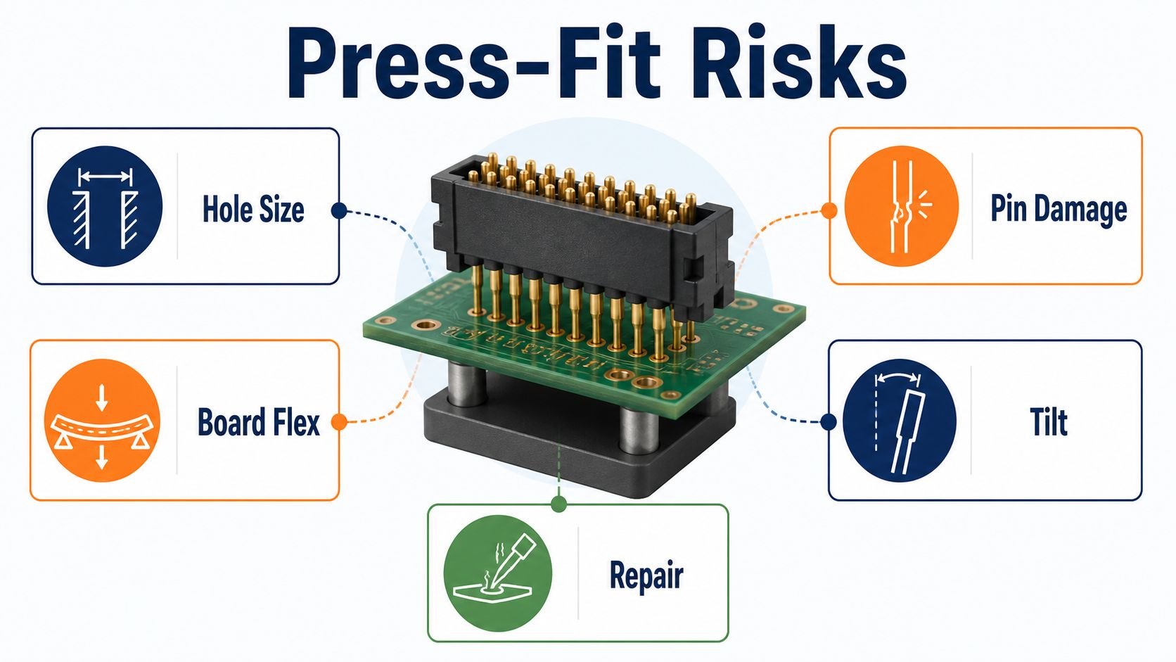
The connector specification usually applies to the finished plated hole, not only the mechanical drill. The fabrication drawing must communicate the finished-hole requirement, plating context, tolerance, and inspection method agreed for the selected part.
Drill size, plating, material behavior, and process variation interact. The verified EBest capability source contains no press-fit-specific entry, so this article does not publish a universal EBest value. The design should be reviewed against the connector data and actual PCB construction.
Design the PCB Layout for Access and Mechanical Support
Provide space for the connector, insertion tool, fixture, board support, and inspection. Keep nearby components, tall hardware, connectors, and underside features clear of the press path and support points.
Review copper, planes, hole-to-feature spacing, board edges, cutouts, stackup, and mechanical loads. The PCB design constraints guide explains why fabrication and assembly limits must be coordinated before release.
Inspect Boards and Connectors Before Insertion
Screen inputs before a press cycle converts an input defect into board damage. Verify part number, orientation, pin condition, hole pattern, board revision, cleanliness, damage, warpage, and required measurements or records.
Protect pins during handling. Bent, contaminated, missing, or previously inserted connectors need disposition before loading.
Build a Fixture That Supports the Board Near the Connector
The fixture should react insertion load without excessive board bending. Support close to the hole field while clearing underside pins, components, solder joints, and tooling features. Use stable datums and prevent reversed loading.
A fixture that supports only the panel edges can allow local flex, laminate stress, or damage to neighboring assemblies. Validate support on the actual board, not a simplified outline.
Align Every Pin Before Force Is Applied
All pins must enter the intended holes without side load or tilt. Use connector and board datums, guiding features, visual checks, or tooling appropriate to the design. Begin with controlled engagement and stop if resistance appears abnormal.
Do not use increasing force to overcome misalignment. A single bent pin can damage plating, enlarge a hole, tilt the connector, or create a latent intermittent connection.
Insert the Connector With a Controlled Press Cycle
Apply load through the approved connector surface and insertion tooling. Control speed, travel, seating reference, parallelism, and stop condition as required by the connector and assembly plan.
Prevent contact with housings or features not designed to carry insertion load. Monitor the board and connector throughout the cycle; unusual sound, tilt, force, or travel requires containment.
Use Force-Displacement Data as Process Evidence
When required, force-displacement monitoring can show whether the cycle followed the approved signature. Define which values or curve features are recorded, how limits are established, how connector pin count affects interpretation, and what happens after an out-of-limit result.
A curve is evidence only when linked to the correct unit, connector, fixture, program, and acceptance rule. Do not publish or apply generic force limits across different connectors.
Inspect Seating, Pins, Holes, and Board Condition
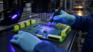
Post-insertion inspection should confirm seating and check for damage introduced by the operation. Inspect connector height or seating feature, tilt, exposed compliant sections where applicable, bent or missing pins, board cracks, mask damage, laminate stress, and nearby components.
Access to both sides and the exact criteria depend on the assembly. Record the result against the lot or serial identity.
Test Electrical Continuity and Product Function
Mechanical seating does not prove electrical performance. Define continuity, isolation, signal, power, programming, or functional checks appropriate to the connector’s role. Preserve first-pass and final results.
The PCB assembly testing services guide helps define limits, logs, retest, and failure disposition. Broader assembly handoff is covered in the PCBA manufacturing guide.
Control Removal, Repair, and Repeat Insertion Risk
Removal is a separate engineered process. Define extraction tooling, board support, connector disposition, hole inspection, allowable replacement, electrical verification, and repeat-cycle rule. Do not assume a hole or pin remains acceptable after extraction.
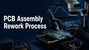
The PCB assembly rework process guide explains authorization, evidence preservation, site inspection, test, and release.
Match the connector, finished hole, fixture, and press plan before production.
Send Gerber or ODB++, BOM, fabrication drawing, stackup, connector part and application specification, 3D/mechanical data, hole requirements, insertion criteria, quantity, test, traceability, and schedule.
Connector | Hole | Stackup | Fixture | Insert | Test | Quantity
Compare Press-Fit Assembly Quotes and Exclusions
Normalize connector sourcing, PCB review, hole inspection, fixture NRE, tooling, press programming, cycle evidence, per-unit insertion, inspection, test, traceability, removal, repair, and exclusions. Two prices are not comparable if one assumes customer-supplied validated tooling while the other includes development.
Ask who owns and maintains the fixture, how connector changes are handled, and how out-of-limit cycles are dispositioned.
Send a Press-Fit RFQ Package Suppliers Can Review
Provide one revision-controlled package. Include PCB fabrication and assembly data, stackup, finished-hole callout, connector data, mechanical model, insertion tool and seating requirements, fixture concept, quantity, forecast, press evidence, inspection, electrical/functional test, traceability, repair rule, packaging, and target date.
Use the traceability guide to define how connector lot, PCB lot, program, curve, inspection, and test are linked.
Press-Fit PCB Assembly Process FAQ
What is a press-fit PCB connection?
It is a solderless connection made when a compliant pin is inserted into a controlled plated through hole.
Is press-fit the same as through-hole soldering?
No. The electrical/mechanical interface comes from the compliant pin and plated hole rather than a solder joint.
Should the drawing specify drill size or finished hole?
The connector requirement normally relates to the finished plated hole; fabrication data must also define the process inputs needed to achieve it.
Why is local board support important?
It reacts insertion load near the connector and reduces flex and stress on the board and neighboring components.
What causes bent press-fit pins?
Misalignment, damaged input parts, hole mismatch, tilted tooling, inadequate guidance, or forcing an abnormal cycle can bend pins.
Is force monitoring always required?
Not universally. Use it when the connector, product risk, customer, or process plan requires it and define the acceptance logic.
How is seating verified?
Use approved mechanical/visual criteria, pin inspection, board condition checks, and electrical or functional test.
Can a press-fit connector be removed and reused?
Do not assume so. Follow connector guidance and engineering disposition for the pin, hole, board, and replacement process.
Can EBest publish a universal press-fit hole tolerance?
No. The original capability source has no press-fit entry; the exact connector, hole, plating, stackup, and process require project review.
What files are needed for a quote?
Send PCB data, stackup, connector specification, hole requirements, mechanical model, fixture/insertion criteria, quantity, test, traceability, and schedule.
Turn the press-fit interface into a controlled manufacturing package.
Email the PCB files, BOM, finished-hole requirements, connector data, mechanical model, fixture and insertion plan, acceptance checks, quantity, and delivery target. EBest Circuit will review the inputs and confirm project-specific support.
Hole spec | Connector | Fixture | Press | Inspect | Test | Release
You may also like




Tags: PCB Assembly, Press-Fit, Quality Control