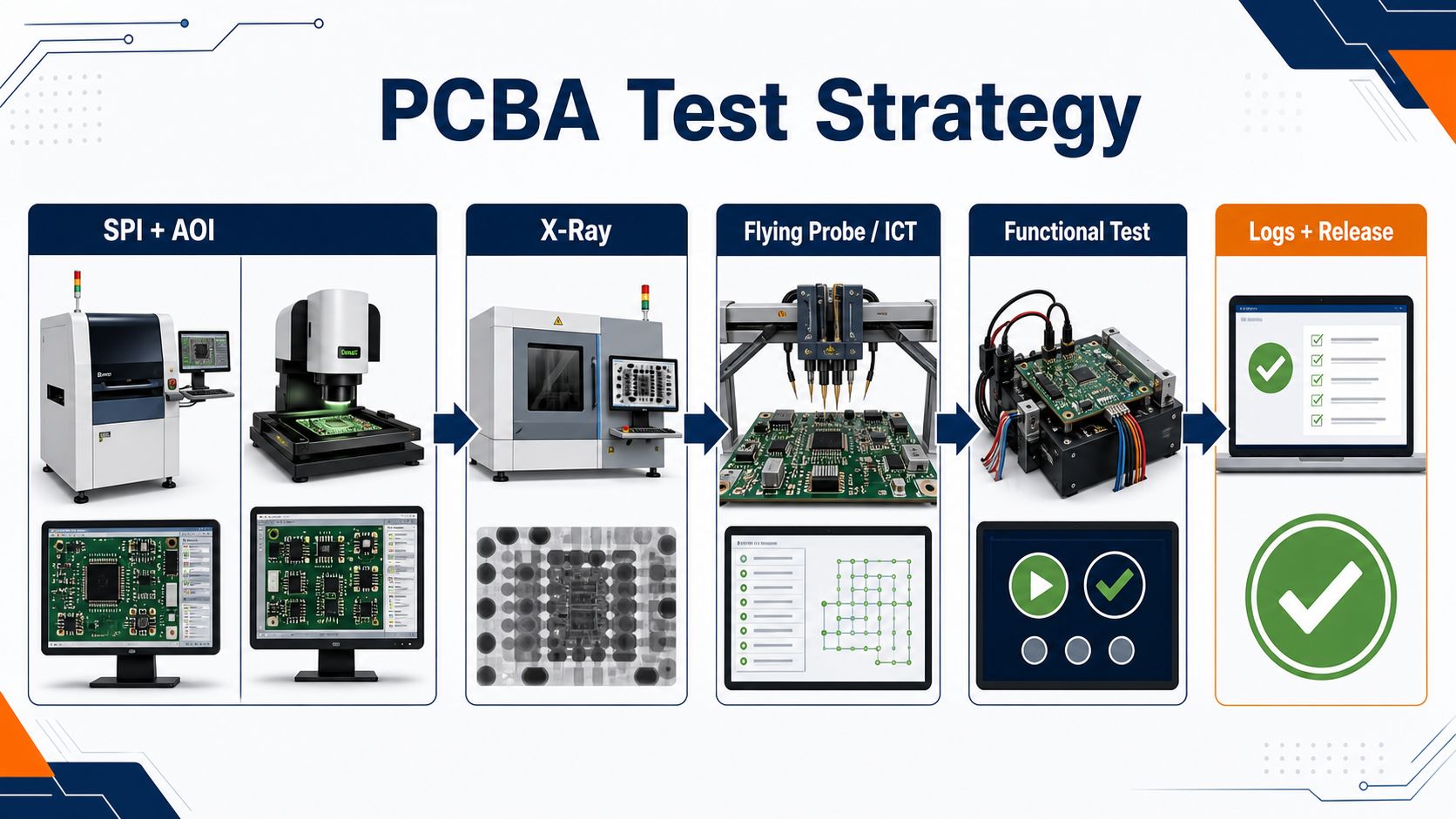
PCB assembly testing services should prove that the assembled board was built correctly and can perform its intended job—not simply that it passed through a test station. The right plan may combine solder-paste inspection, AOI, X-ray, flying probe, in-circuit testing, programming, and functional testing. Each method sees different defects, so the plan must define coverage, limits, records, and failure disposition before production begins.
This guide helps engineers and buyers choose the appropriate layers of evidence for prototypes, NPI builds, and repeat production. It also explains the information an assembly partner needs to quote a test scope without hiding fixture cost, programming work, cycle time, or exclusions.
Will your quoted test plan find the failures that matter to this product?
A generic line item such as “AOI + functional test” leaves critical questions open. Which solder joints are hidden? Are power rails checked before firmware is loaded? Who supplies the test program and golden unit? Which measurements are logged by serial number? What happens after a first failure or an intermittent retest?
EBest Circuit can review the customer’s assembly data and proposed test requirements before confirming an executable project scope.
Send Gerber or ODB++, BOM, CPL, assembly drawings, schematic or netlist where permitted, firmware and checksum, test procedure, interface or fixture information, golden-unit definition, acceptance limits, quantity, reporting needs, and target schedule. Specific equipment, coverage, sampling, and deliverables are confirmed for the actual project rather than assumed from a generic service label.
What PCB Assembly Testing Services Must Prove
A complete plan answers four questions: was the process controlled, is the circuit electrically connected, does the product function, and can the result be traced? Inspection and test are related, but they do not provide interchangeable evidence.
- Process evidence checks paste deposition, placement, polarity, solder-joint appearance, and hidden-joint condition.
- Electrical evidence checks opens, shorts, component values, nets, power rails, or programmed device status.
- Functional evidence applies realistic stimuli and confirms expected outputs, communications, controls, or loads.
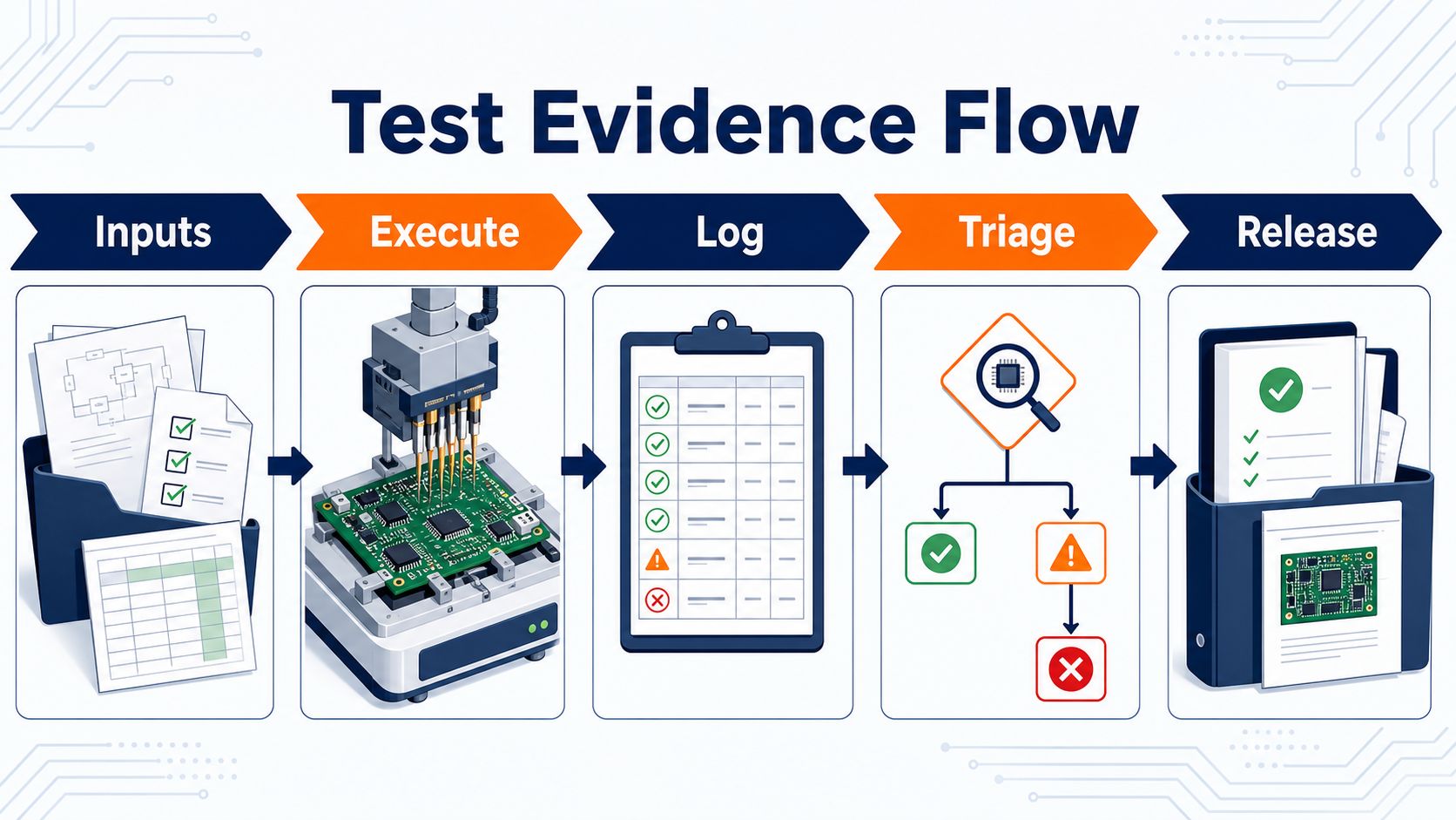
- Release evidence connects the result to the board revision, software revision, serial or lot, limits, operator or station, and disposition.
If the quotation does not identify which of these outcomes are included, the buyer cannot compare coverage or understand what a “tested PCBA” actually means.
Match Each Test Method to the Defects It Can Actually Find
Choose methods from the failure modes, not from a familiar equipment list. A camera can identify visible placement and solder anomalies, but it cannot prove firmware behavior. A net test can find opens and shorts, but it may not reveal a marginal connector or an incorrect system response.
| Method | Best Used For | Important Limits | Quote Inputs |
| SPI / AOI | Paste condition, placement, polarity, visible solder features | Cannot verify every hidden interface or product function | Assembly drawings, polarity references, component data, inspection criteria |
| X-ray | Hidden joints, voiding patterns, bridges, alignment, selected internal features | Image interpretation and acceptance criteria must be defined | Critical packages, joint locations, acceptance or review rules |
| Flying probe | Flexible net, open/short, and selected component checks without a dedicated bed-of-nails fixture | Access, program preparation, and cycle time constrain coverage | CAD/netlist data, schematic, test-point access, quantity |
| ICT | High-throughput electrical checks with dedicated fixture access | Fixture NRE, DFT access, revisions, and maintenance matter | Netlist, test-point map, component limits, forecast volume |
| Functional test | Power-up behavior, interfaces, controls, outputs, and product-level operation | Only proves the conditions, limits, and functions included in the procedure | Procedure, firmware, fixture/interface, loads, limits, golden unit |
The most defensible plan combines methods where their evidence complements rather than duplicates. A high-risk hidden joint may need imaging even if the board later passes a functional sequence; the functional result alone does not reveal joint condition.
Separate Process Inspection from Electrical and Functional Testing
Process inspection prevents and contains manufacturing defects; electrical and functional testing assess the assembled circuit. Keeping those purposes separate makes the control plan easier to diagnose and improve.
For example, AOI may detect a reversed diode immediately after reflow. An electrical test may detect an unexpected rail condition. A functional test may show that an output does not respond. All three observations can point to the same assembly, but they occur at different stages and support different corrective actions.
A quote should therefore state where each check occurs, whether it is 100% or sampled, what condition releases the board to the next stage, and which result is delivered to the customer. Do not let one broad “test” line hide three different responsibilities.
Use SPI and AOI to Control the SMT Process
SPI and AOI are strongest when they feed process control, not when they are treated as end-of-line proof. SPI can identify paste volume, position, bridging, or insufficient deposition before components are placed. AOI can inspect component presence, position, polarity, markings, and visible solder features after placement or reflow.
The useful output is not just pass/fail. Defect categories and location trends can reveal stencil, placement, component, reflow, or programming issues before they spread through a lot. The AOI quality guide explains how optical inspection supports process decisions without replacing electrical or functional evidence.
Before quoting, identify double-sided assemblies, tall components, reflective or unusual parts, polarity-sensitive devices, critical fine-pitch locations, and customer-specific criteria. These affect programming and review effort.
Add X-Ray When Critical Solder Joints Are Hidden
X-ray belongs in the plan when the joint cannot be judged adequately from the surface. Common candidates include BGAs, bottom-terminated components, shielded regions, and other connections where bridges, opens, alignment, or void patterns may be concealed.
The method still needs an inspection question. “X-ray included” does not define which packages are checked, whether inspection is sampled or comprehensive, what image views are required, which conditions trigger review, or what acceptance criteria apply. The automated X-ray inspection guide shows how to convert hidden-joint risk into an inspectable plan.
For the RFQ, mark critical reference designators and state any agreed criteria. If no criterion exists, request an engineering discussion instead of assuming the supplier will infer the intended limit.
Choose Flying Probe When Flexibility Matters More Than Fixture Throughput
Flying probe is often attractive for prototypes and lower-volume builds because it can avoid a dedicated bed-of-nails fixture. Movable probes contact accessible points and execute a program based on the board data and requested checks.
The tradeoff is time and access. Dense assemblies, limited test points, protected nets, component geometry, and long sequences can reduce practical coverage or increase cycle time. Program generation and validation also remain real engineering work even when fixture NRE is lower.
Ask the quotation to identify program preparation, accessible-net coverage, excluded nodes, expected cycle time, debug support, and the form of the output record. That lets the buyer compare flexibility with the cost of slower execution.
Choose ICT When Repeat Volume Justifies a Dedicated Fixture
ICT can provide fast, repeatable electrical checks when the design has suitable test access and the production volume supports fixture investment. A dedicated fixture may check nets, selected component values, polarity, and other electrical conditions defined by the program.
The decision should include more than unit price. Fixture design, fabrication, validation, revision control, storage, maintenance, spare probes, program changes, and ownership all affect lifecycle cost. A board revision that moves test points may require fixture or program work.
Before release, confirm test-pad location, size, side, keep-out, probing direction, grounding strategy, isolation needs, and safe power-up rules. If DFT access is weak, that constraint should be discovered during design review rather than after the fixture quotation.
Use Functional Testing to Prove the Assembly Performs Its Job
Functional testing applies defined power, stimuli, loads, communications, or user actions and compares the measured response with an approved limit. It is the closest assembly-level check to intended operation, but its value is limited by the procedure.
A useful procedure defines connections, power sequence, current limits, firmware version, warm-up time, input conditions, measured outputs, tolerances, timing, communication commands, operator actions, safe shutdown, and required record. “Power on and check” is not reproducible.
Functional test can also conceal ambiguity if failures are handled informally. State whether the fixture, cable, load, instrument, firmware, or golden unit is customer-supplied or supplier-developed; who approves it; and how revisions are controlled.
Plan Programming, Calibration, and Serial Traceability Together
Programming and test data must identify exactly what was loaded, measured, and released. For programmable devices, provide the approved binary, checksum, device location, programming method, lock or security requirements, and version-control rule. If calibration constants are written, define how they are generated, stored, and linked to the unit.
Traceability can connect serial number, PCB revision, BOM revision, firmware, fixture, station, time, result, measurements, and failure code. Not every product needs every field, but the required schema should be agreed before the first lot.
This planning aligns naturally with the broader PCBA manufacturing handoff: design data, components, process records, programming, and release evidence need one revision-controlled identity.
Design the PCB for Test Access Before Release
Testability is cheaper to create in layout than to recover with a complicated fixture. Engineers should review access to power, ground, programming signals, critical nets, communications, resets, analog points, and isolation controls before the board is frozen.
- Provide stable, probeable access where electrical coverage is required.
- Keep test points clear of components, hardware, coatings, and fixture obstructions.
- Define safe power sequencing, current limiting, and discharge behavior.
- Make firmware recovery and programming connections serviceable.
- Provide mechanical datums, support locations, and connector access for the fixture.
- Consider how panelization and depaneling affect test order.
During NPI manufacturing, validate that theoretical access remains practical on the assembled board and that fixture contact does not damage the product.
Build a Fixture and Golden-Unit Strategy That Can Be Maintained
A fixture is a controlled production asset, not a one-time collection of cables. Its drawings, wiring, interface boards, instruments, software, safety controls, calibration needs, spare parts, and revision history should be identifiable.
A golden unit also needs governance. Define why it is representative, which revision it uses, how its behavior was approved, how it is protected from drift or damage, and whether a second reference is kept. A golden unit is useful for station verification, but it should not replace numerical limits where measurements can be defined.
For outsourced assembly, the quotation should clarify ownership, storage, maintenance, validation, and return conditions for fixtures and customer-supplied equipment.
Turn your test idea into a quote-ready PCBA plan.
Send the assembly data, schematic or netlist where permitted, test procedure, firmware, fixture/interface files, limits, golden-unit definition, quantity, traceability fields, and target schedule. EBest Circuit can review open inputs and confirm the project-specific assembly and test scope.
Assembly data | Firmware | Procedure | Fixture | Limits | Logs | Quantity
Define Limits, Logs, Retest Rules, and Failure Codes
Repeatable testing requires a decision rule for every measured or observed result. Define units, nominal values, upper and lower limits, timing windows, rounding, warm-up, sampling where applicable, and whether limits depend on product configuration.
Then define data handling. Which values are logged? Is only pass/fail stored, or are measurements retained? How is a unit identified? What happens if the station loses connection? How long are results retained, and what report accompanies shipment?
Retest rules deserve special attention. A board that fails, passes after reseating, and then passes again is not equivalent to a first-pass unit unless the approved procedure says so. Record first-pass yield separately, use consistent failure codes, and require a disposition for repeated or intermittent results.
Diagnose Failures Without Mixing Design, Process, Component, Firmware, and Fixture Causes
Test failure is an observation, not a root cause. Effective triage keeps the unit identity and first-failure data intact, reproduces the condition safely, and separates possible cause families before rework.
| Cause Family | Evidence to Review | Avoid This Shortcut |
| Design | Schematic intent, tolerances, startup state, loading, margins | Changing the test limit to make an unexplained result pass |
| Assembly process | Inspection images, polarity, solder condition, reflow and lot history | Replacing components before documenting the original condition |
| Component | Lot, date code, substitutions, value, damage, counterfeit controls | Calling every electrical symptom a “bad part” |
| Firmware | File, checksum, configuration, boot log, programming result | Testing mixed software revisions under one result label |
| Fixture or station | Golden-unit check, cables, contacts, instrument status, calibration | Assuming the station is correct because it worked yesterday |
Disposition may be repair, component replacement, firmware correction, fixture maintenance, design review, scrap, or use-as-is under authorized deviation. The decision and supporting evidence should remain linked to the unit.
Compare Coverage, NRE, Cycle Time, and Evidence in the Quote
Two test quotations are comparable only when they promise the same work and evidence. Normalize the method, program and fixture NRE, covered nets or functions, excluded items, quantity, cycle time, operator content, debug allowance, first-article validation, maintenance, retest, failure analysis, data retention, and shipment report.
For prototypes, flexibility and diagnostic visibility may matter more than per-unit throughput. For stable repeat production, fixture investment and automation may reduce cycle time. For safety- or reliability-sensitive products, the evidence and change-control plan may outweigh both.
Do not choose from method names alone. Ask each supplier to show how the proposed sequence maps to the product’s high-risk defects and acceptance decisions.
Send a Test Package Your Assembly Partner Can Execute
A quote-ready package lets the supplier reproduce the test without reconstructing the product from scattered emails. Include:
- Gerber or ODB++, drill data, BOM, CPL, assembly drawings, and current revision;
- schematic, netlist, test-point map, and interface definitions where permitted;
- firmware binary, checksum, configuration, programming and security instructions;
- step-by-step test procedure with power sequence, stimuli, loads, limits, and shutdown;
- fixture drawings, cable/interface data, instrument requirements, and ownership;
- golden-unit definition and station-validation method;
- serial, lot, software, measurement, failure-code, and report requirements;
- quantity, forecast, build stage, failure-analysis expectation, and target schedule.
If the manufacturing package is already organized as intelligent data, the IPC-2581 guide explains how a structured handoff can reduce ambiguity. Regardless of format, confirm that every file carries the same approved revision.
PCB Assembly Testing Services FAQ
What is included in PCB assembly testing services?
Scope can include process inspection, electrical testing, programming, functional testing, result logging, and failure handling. The quotation must identify the exact methods, coverage, limits, records, and exclusions for the project.
Is AOI enough to prove a PCBA works?
No. AOI checks visible assembly features; it does not prove electrical connectivity or intended system behavior. Use electrical or functional testing when those outcomes must be demonstrated.
When is X-ray needed for PCB assembly?
X-ray is useful when critical solder interfaces are hidden, such as under BGAs or bottom-terminated packages. The plan should identify locations, frequency, image views, and acceptance criteria.
What is the difference between flying probe and ICT?
Flying probe offers flexible, fixture-light electrical testing but may have longer cycle time. ICT uses a dedicated fixture for repeatable throughput but requires suitable DFT access and greater NRE.
Does functional testing find every assembly defect?
No. It proves only the functions and conditions in the procedure. A board can pass a limited functional sequence while still containing an untested or latent assembly issue.
Who should provide the PCBA test procedure?
The product owner normally defines intended behavior and acceptance. The assembly partner can review executability and may develop fixtures or programs when that work is included and approved.
What is a golden unit?
A golden unit is an approved reference assembly used to validate a test station or compare behavior. Its revision, approval basis, storage, and periodic verification should be controlled.
What files are needed for a PCB assembly testing quote?
Provide assembly data, schematic or netlist where permitted, firmware, test procedure, fixture/interface data, limits, golden-unit definition, quantity, reporting fields, and delivery target.
Should test measurements be saved by serial number?
Use serial-level records when product risk, traceability, warranty, calibration, or customer requirements justify them. Define the exact fields and retention period before production.
How should retest be handled?
Preserve the first failure, define when retest is allowed, record interventions, and distinguish first-pass yield from final pass. Repeated intermittent failures need disposition, not endless retesting.
How can buyers compare PCBA testing quotations?
Compare coverage, NRE, fixture and program ownership, cycle time, included validation, failure analysis, retest rules, data retention, deliverables, exclusions, and revision-change costs.
Can EBest Circuit confirm a specific test method before reviewing the files?
No specific equipment, coverage, sampling, or functional result should be assumed without project review. EBest Circuit can review the submitted package and confirm an executable assembly and testing scope for the quotation.
Build a PCBA quotation around evidence you can use.
Email Gerber or ODB++, BOM, CPL, drawings, test procedure, firmware, limits, fixture or interface details, golden-unit plan, quantity, reporting needs, and target delivery. EBest Circuit will review the package and confirm the project-specific manufacturing and test scope.
Gerber/ODB++ | BOM | CPL | Firmware | Limits | Fixture | Reports
You may also like






Tags: PCB Assembly, PCB testing, Quality Control