PCB manufacturing PCB manufacturing
Home > Blog

AI PCB Design Tools, Limits and a DFM-Safe Workflow

August 17th, 2026
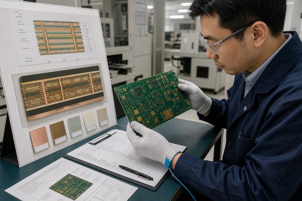
Engineer reviewing an AI-assisted PCB layout with schematic routing and DFM checks
AI can accelerate parts of schematic and layout work, but release authority still belongs to an engineer who can verify electrical intent, physical constraints, and fabrication readiness.

AI PCB design tools can help create circuits, suggest parts, place components, route traces, explain rule violations, and review documentation—but they do not make an unverified layout safe to fabricate. Their best use is to shorten bounded tasks inside a controlled engineering workflow. Requirements, constraints, simulation, DRC, DFM review, and final release approval still need accountable human judgment.

This guide separates useful automation from risky overconfidence. It compares tool roles, identifies decisions that remain engineering work, and provides a release checklist you can use before sending AI-assisted PCB files to a manufacturer.

Can your team prove that the AI-generated board matches the product—not merely that the CAD file opens?

A plausible-looking layout can still contain the wrong footprint revision, a weak return path, unreviewed impedance geometry, inaccessible test points, a copper-to-edge problem, incomplete drill notes, or manufacturing rules copied from the wrong supplier. Those errors become expensive when they survive until fabrication, assembly, or first power-on.

EBest Circuit can review the released manufacturing package against the actual board construction and requested production scope.

Send Gerber or ODB++, NC drill files, fabrication drawing, stackup, material and copper requirements, controlled-impedance notes, netlist or IPC-356 data where available, quantity, surface finish, test requirements, and target delivery. For assembly, also include the BOM, CPL/pick-and-place file, assembly drawings, approved substitutions, and programming or test instructions. Project-specific capability and special-process requirements are confirmed during review rather than inferred from an AI prompt.

Can AI Design a PCB From Schematic to Gerbers?

AI can participate across the workflow, but “design a PCB” covers several different engineering jobs. A text request may produce a circuit concept or first-pass schematic. A placement engine may optimize component locations against encoded goals. An autorouter may complete connections under a defined rule set. A review assistant may explain a DRC finding. None of these steps proves the full product requirement.

The important question is not whether a tool can generate output. It is whether the input constraints are complete and whether the output can be independently verified. A correct netlist does not prove signal integrity. A DRC-clean layout does not prove that the selected rules match the chosen stackup. Generated Gerbers do not prove that drill pairs, impedance callouts, materials, tolerances, assembly clearances, and test access are complete.

For that reason, treat AI output as a candidate design state. A qualified engineer should still approve the circuit, part choices, footprint library, placement, critical routing, power integrity, thermal path, manufacturability, testability, and final release package.

AI PCB Design Tools by Job: Schematic, Placement, Routing and Review

Choose an AI PCB design tool by the task it performs and the evidence you need from that task. “AI-powered” is not a useful comparison unless the buyer knows what enters the system, what it changes, which constraints it honors, and how a human can inspect or override the result.

Tool or approach Useful role Input that must be controlled Engineer must still verify
Flux Browser-based schematic and PCB collaboration with an AI assistant and layout automation Requirements, approved parts, schematic intent, placement constraints, routing rules, stackup assumptions Footprints, critical nets, physical layout, rule completeness, DFM package
Quilter Physics-driven placement and routing from a supplied circuit design and constraints Validated circuit, board outline, constraints, component data, design priorities Whether the completed layout meets product, SI/PI, thermal, test, and manufacturing needs
Cadence Allegro X AI Generative assistance for placement and routing inside a professional PCB environment Constraint system, technology files, library quality, layer strategy, critical-net definitions Constraint accuracy, routing quality, signoff analyses, release data
Zuken CR-8000 AIPR Intelligent place-and-route informed by design libraries and established design practices Reusable design knowledge, validated rules, board architecture, technology setup Project-specific exceptions, performance, manufacturability, final approval

Product functions, licensing, deployment, supported formats, and data-handling terms change. Verify the current version and security model before uploading confidential schematics, component data, or product requirements. Also distinguish a circuit-generation assistant from an autonomous layout system and from conventional rule-based autorouting; their risks and required reviews are not the same.

AI PCB design tool role map for schematic placement routing analysis and manufacturing review
Separate the workflow into roles. A tool may accelerate one stage without owning the requirements, evidence, and approval needed at the next gate.

Where AI PCB Layout Still Needs Engineer Judgment

The hardest layout decisions are often interactions, not isolated rules. Moving a connector may improve enclosure fit but worsen an ESD path. Spreading components may improve assembly access but enlarge a sensitive current loop. Adding copper may help current capacity while changing thermal balance or impedance. AI can search alternatives, but an engineer must decide which tradeoff serves the product.

  • Architecture and safety: isolation boundaries, creepage, clearance, protection devices, grounding concept, and applicable product standards.
  • Signal and power integrity: reference-plane continuity, return-current paths, impedance geometry, crosstalk, differential-pair behavior, decoupling, and power-distribution impedance.
  • Thermal behavior: component loss, heat spreading, copper balance, thermal vias, airflow, enclosure conditions, and temperature-sensitive parts.
  • RF and analog behavior: placement sensitivity, shielding, guard structures, antenna keep-outs, matching networks, noise coupling, and tuning access.
  • Mechanical integration: enclosure tolerances, connector alignment, mounting hardware, rigid-flex bend areas, cable access, and assembly sequence.
  • Manufacturing and test: realistic line/space and hole choices, annular rings, solder-mask geometry, assembly clearances, panel strategy, fiducials, tooling, probing, inspection access, and rework risk.

These decisions also depend on the selected manufacturer’s verified process window. For example, line/space, finished-hole size, aspect ratio, copper weight, material, layer count, and blind/buried-via construction are linked constraints. A value that is routine for one construction may require special review for another. Do not let an AI tool turn a generic rule table into an unconditional fabrication claim.

A Practical AI PCB Design Workflow From Requirements to Release Files

A safe workflow gives AI a narrow job, defines an observable acceptance test, and preserves a human approval gate. Use the following sequence whether the tool assists schematic creation, placement, routing, analysis, or documentation.

  1. Freeze the design brief. Record electrical requirements, interfaces, environment, dimensions, connector locations, compliance needs, test strategy, cost target, quantity, and lifecycle expectations.
  2. Control the component and footprint source. Approve manufacturer part numbers, lifecycle status, ratings, package variants, land patterns, 3D models, pin mapping, and substitution policy. Never accept a generated footprint on appearance alone.
  3. Validate the schematic. Review power sequencing, protection, pull states, unused pins, current paths, tolerance stack-ups, net naming, ERC results, and design calculations. Simulate critical behavior where appropriate.
  4. Define the physical technology. Establish board outline, stackup, copper weights, impedance needs, via strategy, fabrication classes, assembly process, and manufacturer rules before layout automation begins.
  5. Encode constraints by intent. Mark safety regions, high-current paths, high-speed classes, differential pairs, length relationships, return references, keep-outs, placement groups, thermal needs, and test access.
  6. Run AI or automation on a controlled revision. Preserve the input revision, tool version, settings, constraint files, generated output, warnings, and rejected alternatives. This creates a reviewable change instead of an unexplained new baseline.
  7. Review by risk, not by visual neatness. Inspect safety and power first, then clocks and high-speed interfaces, analog/RF regions, thermal paths, mechanical fit, manufacturability, and testability.
  8. Perform independent checks. Run ERC/DRC, connectivity comparison, field-solvers or SI/PI analysis where needed, thermal assessment, 3D/mechanical review, and a manufacturer-aligned DFM check.
  9. Generate and compare release files. Inspect Gerber/ODB++, drills, netlist, drawings, stackup, pick-and-place, BOM, and assembly outputs in viewers independent of the source editor.
  10. Obtain accountable signoff. Identify the engineer approving the circuit, layout, analyses, DFM exceptions, and released revision. An AI conversation is not an approval record.

If your team needs a manufacturing-focused review structure, use this PCB design for manufacturability checklist to connect CAD decisions to fabrication and assembly risks.

12 Checks Before You Trust an AI-Generated PCB Layout

Use this list as a release gate, not as a late visual review. Each item should produce evidence that another engineer can inspect.

  1. Schematic-to-layout connectivity: compare the released netlist and confirm intentional net ties, no-connects, swapped pins, and variant handling.
  2. Library integrity: verify symbol-to-footprint mapping, pad numbering, polarity, courtyard, assembly origin, paste openings, and package revision.
  3. Power entry and protection: inspect current paths, fusing, reverse-polarity protection, surge/ESD parts, sequencing, and fault behavior.
  4. Return paths: trace the reference plane beneath critical signals and inspect every layer transition for a controlled return path.
  5. Impedance and timing: connect stackup geometry to the routed widths, gaps, layers, via structures, length relationships, and simulation assumptions.
  6. Spacing by voltage and environment: verify creepage, clearance, slots, coating assumptions, pollution conditions, altitude, and standard-specific requirements.
  7. Thermal path: review loss estimates, junction limits, thermal vias, copper spreading, heat-sink interfaces, airflow, and neighboring heat sources.
  8. Mechanical fit: compare board, connectors, fasteners, components, keep-outs, cables, and enclosure using the controlled mechanical model.
  9. Fabrication feasibility: check line/space, annular ring, drills, aspect ratio, copper balance, mask dams, board edge clearances, via fill/cap needs, and special processes against the actual construction.
  10. Assembly access: verify polarity visibility, component spacing, paste design, fiducials, tooling, selective-solder needs, inspection views, and rework access.
  11. Test strategy: confirm accessible test points, programming interface, power-up controls, isolation needs, fixture constraints, golden-unit plan, and measurement limits.
  12. Release consistency: ensure the revision, Gerbers/ODB++, drills, drawings, stackup, BOM, CPL, assembly notes, and change log describe the same build.
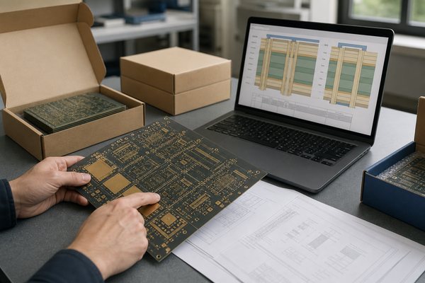
AI PCB design release gates covering requirements electrical review DFM and manufacturing files
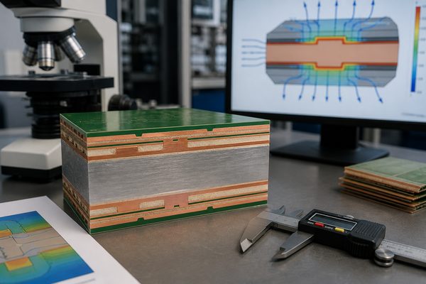
A fabrication-ready release needs four aligned layers of evidence: product requirements, electrical and physical verification, manufacturer-specific DFM, and consistent output files.

When AI Saves Time—and When Manual Layout Is Safer

AI is most useful when success can be expressed as constraints and checked independently. It can accelerate repetitive placement exploration, low-risk routing, component research, documentation, rule explanation, design comparison, and first-pass review. It can also help a small team expose missing questions earlier.

Manual or tightly supervised work is safer when the board contains safety-critical isolation, RF tuning, dense high-speed interfaces, mixed-signal sensitivity, unusual power conversion, extreme thermal conditions, novel packages, complex HDI structures, rigid-flex mechanics, or certification-sensitive requirements. These projects may still use AI, but the automation should not own the critical decision.

Situation Recommended AI role Release condition
Simple controller or adapter with mature interfaces Generate options, assist placement/routing, explain checks Independent schematic, layout, DRC, DFM, and output review
Cost or area exploration Compare constrained alternatives Engineer documents the accepted tradeoff and downstream effects
High-speed, RF, precision analog, or power-dense board Support analysis and bounded optimization Domain specialist approves architecture, models, layout, and measurements
Safety- or compliance-sensitive product Assist documentation and rule discovery Applicable standards and responsible engineer govern every signoff
Prototype intended to become production Accelerate early iterations without weakening records Production stackup, test, panel, component, and process constraints are revalidated

Speed is valuable only when the team can explain what was automated, what was checked, and what remains uncertain. If the verification cost approaches the cost of doing the critical work manually, automation may not be the faster path.

What Files Should Go to the PCB Manufacturer for DFM Review?

Send outputs that define the board, plus the assumptions needed to interpret them. A screenshot, AI transcript, or native CAD file alone is not a manufacturing package.

  • Gerber X2, Gerber RS-274X, or ODB++ data that matches the released revision;
  • NC drill and route data, including plated/non-plated definition and blind/buried-via pairs where applicable;
  • fabrication drawing with board dimensions, tolerances, finished thickness, copper, material, finish, edge treatment, special notes, and revision;
  • proposed stackup and controlled-impedance requirements, including target, tolerance, layer, reference, and coupon expectations;
  • IPC-356 or another suitable netlist for an independent connectivity comparison where available;
  • quantity, panel or delivery preferences, testing requirements, quality documentation, and target schedule;
  • for assembly: BOM with approved manufacturer part numbers, CPL/pick-and-place data, assembly drawing, polarity notes, variant rules, programming, and test instructions.

Use a structured prototype PCB manufacturing RFQ checklist for early builds, then confirm that the same package can scale into repeat production. If supplier selection is still open, this PCB fabrication manufacturer selection guide explains how to compare capability evidence, engineering review, and quote assumptions.

How EBest Circuit Reviews AI-Assisted PCB Files Before Fabrication

The review starts with the released files and the intended construction—not with an assumption that an AI-designed board is either automatically good or automatically risky. The useful question is whether the package can be built, inspected, tested, and traced under an agreed scope.

EBest Circuit can check open manufacturing inputs such as layer definition, outline, drill data, annular features, spacing, copper-to-edge conditions, mask and legend interactions, stackup information, impedance notes, material and finish, panel considerations, fabrication drawings, and file consistency. For assembly projects, the review can extend to BOM/CPL alignment, polarity, package and footprint risks, assembly access, programming, and test inputs.

Capability values are confirmed against the actual construction. Standard and special-process ranges are not interchangeable, and combinations of minimum features, copper, thickness, materials, via structures, tolerances, and delivery needs require project review. For conventional FR-4 work, see the FR-4 PCB manufacturing overview; for microvia and high-density work, use the HDI PCB capability page as a starting point and submit the real stackup for confirmation.

If assembly is part of the build, include all controlled procurement and placement data so the fabrication and PCBA reviews describe one product. The custom PCB assembly guide shows how BOM, CPL, approved substitutions, inspection, programming, and testing affect the quote.

FAQ About AI PCB Design

Can AI design a complete PCB?

AI can generate or automate parts of the schematic and layout workflow, and some systems can complete placement and routing from supplied design data and constraints. A complete product still needs verified requirements, libraries, analyses, manufacturing rules, output checks, and accountable engineering approval.

Which AI tool is best for PCB design?

The best choice depends on the job. A schematic assistant, autonomous layout engine, professional place-and-route feature, and review assistant solve different problems. Compare supported formats, constraint depth, output inspectability, collaboration, IP controls, toolchain compatibility, and the amount of expert review required.

Can AI generate a PCB from a schematic?

Some tools can create placement and routing from a validated schematic or netlist plus board and routing constraints. The schematic alone is not enough: stackup, board outline, component locations, interfaces, power and signal classes, keep-outs, thermal needs, mechanical limits, manufacturing rules, and test access also matter.

Will AI replace PCB designers?

AI is more likely to change how designers explore, route, document, and review boards than to remove responsibility for product decisions. Engineers remain necessary for architecture, tradeoffs, constraint definition, analysis, safety, manufacturability, failure learning, and release signoff.

Can I use an AI-generated PCB layout for production?

Yes, if it passes the same engineering and manufacturing gates required for any production layout. Verify electrical behavior, libraries, signal/power integrity, thermal and mechanical performance, DRC, DFM, testability, output consistency, and revision control before release.

Is a DRC-clean AI layout ready to fabricate?

No. DRC only checks the rules that were encoded. It cannot prove that the rules match the selected stackup, manufacturer, product standard, assembly process, mechanical design, test strategy, or real operating environment.

What should I send for a DFM review of an AI-assisted board?

Send Gerber or ODB++, NC drills, fabrication drawing, stackup, material and copper requirements, impedance notes, netlist data where available, quantity, finish, testing needs, and target delivery. Add BOM, CPL, assembly drawings, substitutions, programming, and test instructions for PCBA.

You may also like

0.3mm FR4 PCB for IoT Communications: RF Design and Manufacturing Guide

August 17th, 2026

Compact IoT products often need a thinner circuit board without moving to a flexible PCB. A 0.3mm FR4 PCB for IoT communications can reduce the electronic stack height while keeping the familiar material system, component mounting, and assembly methods of a rigid board.

That makes it useful for Bluetooth devices, Wi-Fi modules, wireless sensors, trackers, smart tags, and other products where internal space is tight. The trade-off is that a thinner FR4 construction changes board stiffness, RF geometry, manufacturing handling, and SMT support. These points should be considered before the stack-up is finalized.

0.3mm FR4 PCB for IoT communications with Bluetooth and Wi-Fi applications

What Is a 0.3mm FR4 PCB?

A 0.3mm FR4 PCB is an ultra-thin rigid printed circuit board with a finished thickness of approximately 0.3mm, or about 11.8 mil. It uses glass-reinforced epoxy laminate as the insulating and structural substrate, just like conventional FR4 boards, but with a much thinner overall construction.

In most PCB specifications, 0.3mm refers to the finished board thickness, including the dielectric structure and copper layers. It should not be confused with a 0.3mm FR4 core, which would result in a thicker finished PCB after copper, plating, and surface coatings are added.

Compared with common 0.8mm, 1.0mm, or 1.6mm rigid boards, a 0.3mm board has much lower stiffness and is generally considered an ultra thin FR4 PCB. It is still a rigid-board construction rather than an FPC.

Why Use a 0.3mm Ultra Thin FR4 PCB for IoT Communications?

The main reason is to reduce the PCB’s contribution to overall product thickness. In compact IoT hardware, even a fraction of a millimeter can affect battery clearance, antenna placement, housing design, or the final device profile.

Typical applications include:

  • Bluetooth Low Energy sensor nodes;
  • Wi-Fi communication modules;
  • smart tags and asset trackers;
  • sub-GHz wireless sensors;
  • compact access-control devices;
  • lightweight handheld electronics;
  • thin wearable products where the PCB remains fixed in position.

A 0.3mm board is most useful when enclosure height is genuinely constrained. If product thickness is already determined by a tall connector, display, or battery, reducing the PCB from 0.8mm or 1.0mm to 0.3mm may provide little practical benefit.

For many low-power IoT products, the attraction is therefore mechanical rather than electrical: the board stays rigid enough for conventional component mounting while occupying much less vertical space.

0.2mm vs 0.3mm vs 0.4mm FR4 PCB: Which Thickness Is Better?

The right thickness is usually the thinnest construction that solves the mechanical problem without adding unnecessary fabrication and assembly difficulty.

For a broader baseline, compare these options with the standard PCB thickness used in conventional rigid boards.

Finished Thickness Mechanical Behavior Manufacturing / Assembly Typical Use
0.2mm Very low stiffness Requires careful support and handling Severe z-height restrictions
0.3mm Thin with moderate rigidity Practical with suitable panel support Compact IoT modules and sensors
0.4mm More rigid Easier to process and assemble Thin electronics with slightly more clearance
0.8–1.0mm Conventional rigid behavior Relatively straightforward Moderate thickness constraints
1.6mm High rigidity Standard PCB construction Products without tight z-height limits

For many IoT products, 0.3mm is a useful middle ground between extreme thinness and manufacturing robustness. Going to 0.2mm or even 0.1mm should be driven by a real packaging requirement, because board dimensions, copper weight, layer count, and panel design all become more influential as stiffness decreases.

Comparison of 0.2mm 0.3mm and 0.4mm FR4 PCB thickness and stiffness

How Does 0.3mm FR4 Thickness Affect RF and Signal Performance?

PCB thickness changes the spacing between signal traces and their reference plane. That spacing is one of the main variables used to calculate characteristic impedance.

A 50Ω RF trace designed for a 1.0mm or 1.6mm PCB should therefore not be copied directly onto a 0.3mm board. The required trace geometry must be recalculated using the actual stack-up.

The main variables are:

  • dielectric height;
  • trace width;
  • copper thickness;
  • dielectric constant;
  • reference-plane location;
  • solder mask, when included in the impedance model.

With a smaller dielectric spacing, a 50Ω trace may need to be narrower. This can affect RF IC fan-out, connector launches, spacing to nearby copper, and manufacturable line-width tolerance.

The same principle applies to differential signals. If an IoT board also carries USB, Ethernet, high-speed memory, or other controlled-impedance interfaces, their geometry should be calculated from the final stack-up rather than scaled from a thicker reference design.

RF performance and 50 ohm controlled impedance on 0.3mm FR4 PCB

What FR4 Dielectric Constant Should You Use for IoT PCB Design?

There is no single dielectric constant that represents every FR4 laminate. The familiar value of 4.4 is useful as a rough reference, but it should not automatically be used for final RF calculations.

Actual Dk varies with factors such as:

  • laminate family;
  • glass style;
  • resin content;
  • construction;
  • test frequency.

For early feasibility work, a nominal FR4 value is usually enough to estimate trace geometry. For final RF or impedance design, use the laminate manufacturer’s design-relevant Dk whenever that data is available.

It is also important to separate Dk from Df. Dk influences impedance and electrical wavelength, while Df relates to dielectric loss. For a short RF feed in a compact Bluetooth or Wi-Fi device, ordinary FR4 may be adequate. Longer RF paths or stricter loss budgets may require tighter control of both values.

If electrical performance depends on a specific Dk or Df, the fabrication specification should name the laminate or define an acceptable material range instead of stating only “FR4.”

Can a 0.3mm FR4 PCB Support Controlled Impedance?

Yes. A 0.3mm FR4 PCB can support controlled impedance as long as the stack-up produces trace dimensions that the fabricator can manufacture consistently.

A practical controlled impedance PCB design must use the approved production stack-up rather than nominal board thickness alone.

For impedance-controlled nets, define:

  • target impedance, such as 50Ω single-ended;
  • required tolerance;
  • signal layer;
  • reference plane;
  • copper thickness;
  • dielectric construction;
  • solder-mask condition;
  • coupon or TDR requirements, if needed.

On a very thin stack-up, the calculated trace can become narrow. If the geometry approaches the manufacturer’s process limit, the better solution is usually to adjust the construction rather than force an unnecessarily difficult trace width.

Possible adjustments include changing dielectric spacing, copper weight, layer arrangement, or transmission-line structure. These decisions are much easier to make before routing is finalized.

How Should PCB Antennas Be Designed on 0.3mm FR4?

A PCB antenna must be designed around the actual substrate and board geometry. Changing from a thicker reference PCB to 0.3mm FR4 can alter antenna impedance and resonance, even if the copper outline remains unchanged.

This section works as a compact PCB antenna design guide for thin rigid IoT boards, but final tuning must still be completed in the real enclosure.

Several layout details deserve particular attention:

  • Antenna placement: keep the antenna near the intended board edge and preserve its keep-out region.
  • Ground structure: ground-plane dimensions and nearby copper can influence antenna behavior.
  • Feed line: calculate the feed using the actual 0.3mm stack-up.
  • Matching network: leave room for the recommended tuning components.
  • Nearby hardware: batteries, shielding, displays, cables, metal fasteners, and the enclosure can shift antenna performance.

For Bluetooth, Wi-Fi, and similar IoT products, the antenna should be evaluated after it is installed in the final mechanical environment. A PCB antenna that performs well in free space can behave differently once the battery and enclosure are in place.

PCB antenna design on 0.3mm FR4 with keep-out area matching network and feed line

What Stack-Up and Copper Thickness Work for a 0.3mm FR4 PCB?

A 0.3mm finished thickness leaves limited space for dielectric material, copper, plating, and solder mask, so the stack-up has to be planned more carefully than on a conventional board.

The FR4 PCB copper thickness must be included in the total 0.30mm finished-thickness budget.

The construction is mainly influenced by:

  • layer count;
  • copper weight;
  • required dielectric spacing;
  • via structure;
  • impedance requirements;
  • finished-thickness tolerance.

A two-layer 0.3mm PCB is generally easier to implement because the material structure is relatively simple. Multilayer versions can also be produced, but the available thickness must be divided among multiple cores, prepregs, and copper layers.

Copper weight should match the electrical need rather than defaulting to a heavier specification. For many low-power IoT circuits, lighter copper gives more freedom for fine routing and controlled-impedance geometry. Heavier copper uses more of the total thickness budget and can make fine-line etching more difficult.

If the requirement is 0.30mm finished thickness, state that directly. Do not specify a 0.3mm FR4 core unless the core itself is the intended requirement.

0.3mm FR4 PCB stack-up showing top copper dielectric and bottom copper thickness budget

What Manufacturing Challenges Come With an Ultra Thin FR4 PCB?

The main fabrication issue is reduced panel stiffness. Thin FR4 can move, bow, or distort more easily during processing, particularly when the board outline is large.

Manufacturing control usually needs more attention in several areas:

  • Panel handling: thin panels require better support during transfer and processing.
  • Registration: dimensional movement can affect layer-to-layer alignment on dense designs.
  • Drilling and routing: stable fixturing helps prevent board movement.
  • Solder mask: coating and curing should maintain alignment and flatness.
  • Depanelization: excessive bending can damage thin boards or assembled components.
  • Final inspection: warpage and dimensional stability need closer attention.

Board size is important here. A small 0.3mm IoT module is much easier to handle than a large 0.3mm panelized circuit with the same nominal thickness.

For this reason, manufacturing feasibility should be reviewed using the actual board outline, layer structure, copper weight, feature sizes, and panel design rather than thickness alone.

How Does 0.3mm PCB Thickness Affect SMT Assembly?

A 0.3mm PCB needs more mechanical support during assembly because it can deflect under stencil pressure, conveyor handling, and thermal stress.

The main assembly considerations are:

  • stable panelization;
  • adequate underside support during solder paste printing;
  • reliable conveyor transport;
  • reflow warpage;
  • component weight and distribution;
  • controlled depanelization.

Lightweight IoT assemblies are generally easier to process. Boards populated mainly with QFN, LGA, small sensors, and passive components place less mechanical stress on the PCB than designs carrying large connectors, transformers, inductors, or heavy shielding cans.

Prototype assembly should ideally use the intended production panel rather than loose individual boards. This exposes printing, transport, reflow, and depanelization issues before the design moves into volume production.

Manufacturing and SMT assembly process for 0.3mm FR4 PCB with panel support stencil printing reflow and depanelization

0.3mm FR4 PCB vs Flex PCB vs RF Laminate: Which Should You Choose?

The choice depends on the main requirement. Thin FR4 suits a low-profile rigid circuit, flex PCB suits a circuit that must bend, and low-loss RF laminate suits designs where dielectric loss or RF consistency is more important than standard FR4 economics.

Requirement 0.3mm FR4 PCB Flex PCB Low-Loss RF Laminate
Thin profile Very good Excellent Depends on construction
Repeated bending Poor choice Excellent Generally not the purpose
Rigid component platform Good Requires support consideration Good
Conventional SMT Familiar More support often needed Similar to rigid PCB
Material cost Usually economical Usually higher Usually higher
RF consistency Adequate for many IoT designs Material-dependent Typically better controlled
Compact BLE/Wi-Fi product Strong candidate Useful if folding is needed Often unnecessary
Dynamic wearable Limited Strong candidate Limited
Demanding RF transmission path Evaluate carefully Specialized Strong candidate

A Bluetooth or Wi-Fi design does not automatically require a premium RF laminate. Short RF feeds and properly tuned antennas can work well on suitable FR4. Likewise, thin FR4 should not be used as a substitute for FPC when repeated bending is part of normal operation.

How Should You Specify a 0.3mm FR4 PCB for Manufacturing?

A clear fabrication package is especially important for ultra-thin boards because thickness, copper, stack-up, and impedance requirements interact with each other.

Define the FR4 PCB thickness tolerance on the fabrication drawing when enclosure fit, connector alignment, or RF geometry depends on it.

For quotation and DFM review, provide:

  • finished board thickness and tolerance;
  • layer count;
  • board dimensions;
  • copper weight;
  • preferred FR4 material, if required;
  • Dk/Df requirements, where relevant;
  • stack-up, if already approved;
  • controlled-impedance targets and tolerance;
  • minimum line/space;
  • hole and via requirements;
  • surface finish;
  • Gerber or ODB++ files;
  • NC drill files;
  • fabrication drawing;
  • panelization requirements;
  • assembly files, if PCBA is required;
  • RF-critical dimensions and antenna keep-out areas.

If the stack-up has not been finalized, it is usually better to specify the electrical requirement and allow the fabricator to propose a manufacturable construction. For example:

Finished thickness 0.30mm, 2-layer FR4, 50Ω RF feed, final trace geometry to be confirmed against the production stack-up.

For projects reviewed by EBest Circuit, sending the complete fabrication package together with RF, impedance, and assembly requirements helps engineering distinguish fixed specifications from items that can still be adjusted before prototyping.

FAQs About 0.3mm Ultra Thin FR4 PCB

Is a 0.3mm FR4 PCB flexible?

It can bend more easily than a normal 1.0mm or 1.6mm rigid PCB, but it should not be treated as a flex circuit. Use it where a thin rigid board remains substantially flat in service. If the circuit must repeatedly bend or fold, use an FPC construction designed for that mechanical duty.

How thin can an FR4 PCB be?

FR4 PCBs can be manufactured below 0.3mm, but there is no universal “thinnest FR4 PCB” specification. The achievable thickness depends on board size, layer count, copper, dielectric construction, feature density, panel support, and the manufacturer’s process. Very thin values such as 0.1mm should be confirmed against the actual design rather than treated as standard capability.

Can a 0.3mm FR4 PCB have multiple layers?

Yes, but the thinner the finished board becomes, the less thickness is available for cores, prepregs, copper, and plating. Two-layer construction is relatively straightforward to evaluate. A 0.3mm multilayer PCB should be designed around a manufacturer-approved stack-up before routing and impedance geometry are finalized.

Can a 0.3mm FR4 PCB be used for Bluetooth or Wi-Fi antennas?

Yes. FR4 PCB antennas are used in many 2.4GHz applications, but antenna geometry should be designed or retuned for the actual board material, thickness, ground structure, enclosure, and feed line. Reference-antenna dimensions from another PCB thickness should not be copied blindly.

What dielectric constant should I use for a 0.3mm FR4 PCB?

Use the Dk associated with the actual laminate construction and relevant frequency whenever impedance or antenna performance is important. Do not assume every FR4 material has a dielectric constant of exactly 4.4. Published laminate data shows that Dk can vary with resin content, glass construction, and frequency.

How Can EBest Circuit Support Your 0.3mm FR4 PCB Project?

At EBest Circuit, we support ultra-thin FR4 PCB fabrication, controlled-impedance review, and PCB assembly for compact IoT products. We review the finished thickness together with the stack-up, copper weight, board dimensions, RF requirements, panel design, and assembly conditions.0.3mm FR4 PCB is a practical choice when an IoT product needs a thin rigid circuit without the bending requirements of FPC or the added cost of a specialized RF laminate. The key is to treat the 0.3mm thickness as part of the electrical and manufacturing design, not just as a mechanical specification.

Send us your Gerber or ODB++ files, fabrication drawing, target thickness and tolerance, stack-up, impedance targets, BOM, assembly files, and quantity at sales@bestpcbs.com.

You may also like

Heavy Copper PCB for Battery Systems: BMS Design and DFM Guide

August 17th, 2026
Heavy Copper PCB for Battery with thick copper power layers and a battery module

A heavy copper PCB for battery systems combines high-current power paths with the sensing, protection, and control circuits required by a battery management system (BMS). It can reduce conductor resistance and spread heat, but copper weight alone does not prove that a board can carry a target current. Trace geometry, layer position, vias, terminals, ambient temperature, duty cycle, airflow, and allowable temperature rise must be evaluated together.

This guide shows engineers and buyers how to turn current, voltage-drop, thermal, and mechanical requirements into a manufacturable PCB specification. It also explains where a busbar, embedded copper structure, or metal-core PCB may be a better fit.

What Is a Heavy Copper PCB for Battery Systems?

A heavy copper battery PCB uses thicker-than-standard copper on one or more layers to carry and distribute power between battery terminals, protection devices, switching components, loads, chargers, or contactors. The term has no single universal IPC threshold, so the fabrication drawing must state the finished copper requirement for every layer instead of relying on the words “heavy copper.”

In a BMS, the board may combine two very different electrical zones:

  • Power path: battery terminals, fuses, MOSFETs, shunts, pre-charge circuits, and high-current connectors.
  • Control path: cell-voltage measurement, temperature sensing, isolation, communications, and the BMS controller.

The layout should keep these functions electrically and thermally coordinated without forcing sensitive measurement traces to share noisy or high-resistance return paths.

Why Do Battery and BMS Designs Use Heavy Copper PCBs?

Battery and BMS designs use heavy copper when standard copper cannot meet the required resistance, temperature-rise, transient-current, or mechanical-connection targets within the available board area.

  • Lower resistance reduces I²R loss and voltage drop along the power path.
  • A larger copper cross-section spreads heat away from MOSFETs, shunts, fuses, and terminals.
  • Thicker copper can improve the mechanical robustness of high-current pads and bolted connections.
  • Power and control functions can remain on one assembly when the current level and manufacturing process allow it.

These benefits are conditional. A narrow neck-down, a small connector pad, insufficient via area, or an undersized terminal can become the actual bottleneck even when the main plane is thick.

Battery BMS PCB showing wide heavy copper paths, MOSFETs, terminals, and via arrays

How Do You Reduce Voltage Drop in a Battery PCB?

Reduce voltage drop by lowering the resistance of the complete current path: increase copper cross-section, widen or shorten conductors, remove neck-downs, add properly sized parallel planes or via arrays, and reduce resistance at terminals, connectors, shunts, and solder joints. Increasing copper weight generally lowers DC resistance and conductor heating for the same width and length, but it does not create a universal ampacity rating because current capacity depends on the complete thermal environment.

IPC-2152 provides conductor-sizing guidance and charts for the relationship among current, conductor size, layer position, environment, and temperature rise. IPC now lists IPC-2152 as no longer maintained, so use it as an engineering reference and confirm the current customer, regulatory, and contract requirements for the project. IPC-2221C is the current generic printed-board design revision listed by IPC.

Input Why It Matters
Continuous and peak current Defines steady heating and short-duration stress.
Allowed voltage drop Sets the resistance budget for planes, neck-downs, vias, joints, and terminals.
Allowed temperature rise Determines how much conductor heating is acceptable above ambient.
Layer and cooling condition External and internal conductors reject heat differently.
Trace length and geometry Long paths, corners, slots, and narrow sections add resistance and hot spots.

For the DC path, calculate resistance across the full conductive loop, then confirm the result with electrothermal simulation or a representative test board. Include copper-temperature rise because copper resistance increases as it gets hotter.

What Copper Weight Should You Use for a Battery BMS PCB?

Choose copper weight from the continuous and peak current, trace geometry, allowable temperature rise, voltage-drop budget, layer position, cooling condition, and the fabricator’s process limits. There is no reliable universal copper weight for every BMS, so calculate the path first and confirm it through DFM and thermal testing.

Nominal 1 oz copper is approximately 35 µm (1.4 mil), while 2 oz copper is approximately 70 µm (2.8 mil). Thicker copper increases the total board thickness and can add lamination and drilling constraints.

Is 2 oz copper enough for a battery PCB? Two-ounce copper can be enough when the current path is sufficiently wide and short and the resulting voltage drop and temperature rise stay within the design limits. It is not automatically sufficient for a battery PCB; vias, terminals, connectors, ambient temperature, duty cycle, and cooling can change the result.

Copper Choice Typical Design Use Required Check
1 oz Signals, sensing, and lower-current distribution Confirm that width and temperature rise meet the load.
2 oz Moderate power paths where board area is available Verify neck-downs, vias, connector pads, and finished copper.
3 oz or heavier Higher-current or lower-resistance power sections Obtain an early stackup and DFM review for spacing, resin fill, drilling, and assembly.

Do not specify the same copper weight on every layer by habit. A mixed-copper construction may reduce cost and improve routing, but it requires a fabricator-approved stackup and clear finished-copper notes.

Heavy Copper PCB Stackup: What Must the Fabricator Review?

A heavy copper PCB stackup must balance finished copper, dielectric thickness, resin fill, symmetry, drill aspect ratios, total board thickness, and the electrical separation needed by the battery voltage.

  • State base foil and finished copper separately when plating changes the final value.
  • Keep the construction mechanically balanced to reduce bow and twist.
  • Provide enough resin to fill around thick etched copper without voids or thin dielectric areas.
  • Review via diameter, finished hole, annular ring, and plating for the real current and layer transitions.
  • Identify controlled-impedance or sensitive measurement layers that should not be distorted by adjacent heavy copper.
  • Define creepage and clearance from the maximum working voltage, pollution environment, coating, altitude, and applicable safety standard.

Do not select spacing from a generic voltage table alone. IPC-2221C is a generic design reference, while the end product may also be governed by battery, automotive, industrial, or safety requirements.

Exploded heavy copper PCB stackup with thick inner and outer copper layers and plated vias

How Should Thermal Management Be Verified?

Thermal management should be verified from the worst credible current, ambient temperature, enclosure, duty cycle, airflow, neighboring heat sources, and cooling path—not from copper weight alone.

  1. Build a loss model for copper paths, MOSFETs, shunts, fuses, connectors, and joints.
  2. Locate likely hot spots at neck-downs, via fields, terminal transitions, and component pads.
  3. Run coupled electrical and thermal simulation when current density or enclosure temperature is high.
  4. Measure a representative assembly under continuous current, peak-current pulses, charging, and fault-relevant conditions.
  5. Record copper or component temperature at thermal equilibrium and compare it with design limits and component derating.

Thermal vias help only when they connect to a useful heat-spreading or heat-sinking structure. A dense via field that terminates in a small internal island may add little cooling and can complicate fabrication.

Heavy Copper PCB Design: Which Rules Matter Most?

Heavy copper PCB design succeeds when every transition in the current path has enough electrical, thermal, and mechanical margin. The main plane is rarely the only feature that determines performance.

  • Avoid bottlenecks: keep effective width through pad entries, fuse areas, slots, and component breakouts.
  • Use gradual transitions: reduce abrupt width changes and sharp inside corners in high-current paths.
  • Size via arrays as conductors: calculate the total plated cross-section and current sharing, then verify fabrication limits.
  • Separate sensing from load current: use Kelvin connections for shunts and other low-level measurements.
  • Plan assembly: thick copper is a heat sink, so large terminals and components may need a tailored soldering profile or selective process.
  • Control copper balance: uneven density can affect etching, lamination, flatness, and soldering.

Use our PCB design tools for early trace and via checks, but treat calculator output as a starting point. The final design still needs stackup-specific DFM and thermal validation.

What Manufacturing Risks Should Be Cleared During DFM?

DFM should clear etching, plating, lamination, drilling, solder mask, surface finish, profiling, and assembly risks before the production data is released.

  • Minimum trace and spacing must match the copper thickness and process.
  • Finished copper tolerance must be reflected in resistance and clearance calculations.
  • Prepreg type and resin content must fill the topography around heavy copper.
  • Drill and plating requirements must support current-carrying vias and bolted terminals.
  • Solder mask dams and clearances must remain producible over tall copper features.
  • Panel design and copper distribution must control flatness and dimensional stability.
  • Assembly profiles must account for the board’s higher thermal mass.

Send the fabricator the native Gerber or ODB++ data, drill files, netlist, stackup, fabrication drawing, current requirements, and any impedance or safety notes early enough to change the layout.

Can a Heavy Copper PCB Replace a Busbar in a Battery Pack?

A heavy copper PCB can replace a busbar when its conductor geometry, terminals, thermal path, fault-current behavior, and mechanical strength meet the battery pack requirements. A busbar is usually preferable when very high current, low inductance, bolted connections, or limited board area makes the PCB solution impractical; many systems use both.

Structure Best Fit Main Tradeoff
Heavy copper PCB Integrated power, control, sensing, and interconnect on one board Thick-copper DFM and assembly thermal mass
Busbar or busbar PCB Very high current, low inductance, or robust bolted connections Mechanical integration and added part interfaces
Embedded copper PCB Localized high-current or heat-spreading sections Specialized construction and supplier capability
Metal-core PCB Heat spreading to a chassis or heatsink, often with simpler layer needs Electrical isolation and multilayer routing constraints

A hybrid assembly can be the best answer: a busbar handles the main battery current while a PCB carries gate drive, sensing, balancing, and communication circuits.

How Should Heavy Copper Battery PCBs Be Tested?

Testing should prove conductor integrity, isolation, resistance, thermal behavior, and assembly quality under the conditions defined by the battery system.

  • Fabrication checks: electrical test, finished copper verification, hole and plating inspection, and microsection review.
  • Low-resistance measurement: four-wire measurement across the complete current path, including terminals and joints.
  • Thermal test: continuous and pulsed load testing with temperature measurements at predicted hot spots.
  • Isolation test: apply the project-specific dielectric or insulation test method where required.
  • Assembly inspection: verify solder joints, voiding criteria where relevant, terminal torque process, and cleanliness.
  • Functional test: confirm sensing accuracy, MOSFET switching, protection thresholds, communications, and fault behavior.

The acceptance criteria should be agreed before fabrication. “Passes current” is not enough unless the allowable voltage drop, temperature rise, duration, ambient, and measurement points are defined.

Quality engineer inspecting a heavy copper battery PCB with microscopy and thermal test equipment

What Determines Heavy Copper PCB Price?

Heavy copper PCB price is driven by copper weight, layer count, board and panel size, stackup complexity, spacing, drilling, plating, surface finish, testing, quantity, and yield risk. The same outline can have very different pricing when the copper distribution or DFM margin changes.

The fastest way to obtain a useful quotation is to provide fabrication data rather than a layer count and copper weight alone. Pricing may increase when a design requires unusual material combinations, tight spacing at high copper weight, extensive resin filling, special via structures, strict flatness, impedance control, heavy selective plating, or additional coupons and tests.

What Files Should You Send for a Heavy Copper Battery PCB Quote?

  • Gerber or ODB++ files, NC drill files, IPC-356 netlist, and fabrication drawing
  • Layer count, board thickness, material requirements, and proposed stackup
  • Base and finished copper for each layer
  • Continuous current, peak current, pulse duration, and duty cycle
  • Maximum allowed voltage drop and temperature rise
  • Maximum working voltage and applicable insulation or safety standard
  • Terminal, connector, fastener, and assembly requirements
  • Surface finish, solder mask, controlled impedance, and test requirements
  • Prototype quantity, production volume, and target schedule

At EBest Circuit, we manufacture heavy copper PCBs. Review our heavy copper PCB manufacturing page, then send us the complete data package for a stackup and DFM review.

FAQ About Heavy Copper PCB for Battery Systems

Do batteries have PCBs?

Many battery packs use one or more PCBs for monitoring, protection, balancing, communications, and switching. Small packs may use a compact protection board, while larger systems may use a separate BMS controller and high-current switching assembly.

How thick is 2 oz of copper on a PCB?

Nominal 2 oz copper is about 70 µm or 2.8 mil before process tolerances and final plating effects are considered.

How thick is 3 oz of copper on a PCB?

Three-ounce copper is commonly treated as roughly three times the nominal thickness of 1 oz foil, but the released drawing should use the fabricator’s approved finished-copper specification and tolerance rather than a nominal conversion alone.

How much voltage can a PCB handle?

A PCB has no single voltage limit. The safe working voltage depends on conductor spacing, creepage, clearance, dielectric construction, coating, contamination, altitude, manufacturing tolerances, and the applicable product-safety standard. Define the maximum working and transient voltage before the stackup and spacing review.

How does copper weight affect voltage drop in a battery PCB?

Heavier copper increases conductor cross-sectional area and generally reduces resistance and voltage drop when width and length stay the same. The total drop still includes neck-downs, vias, shunts, connectors, terminals, solder joints, and the higher resistance of hot copper.

What information affects heavy copper PCB price for a battery project?

Price is affected by copper weight, layer count, board and panel size, stackup, material, spacing, drilling, plating, surface finish, test requirements, quantity, and expected yield. Complete fabrication data produces a more useful quotation than copper weight and dimensions alone.

When is a busbar better than a heavy copper PCB?

A busbar is often better when current, mechanical connection, low inductance, or board-area constraints make a PCB power path impractical. A hybrid busbar-plus-control-PCB design is common in high-power systems.

Technical references: IPC-2152 table of contents and the IPC standards revision table.

How Can EBest Circuit Support Your Heavy Copper Battery PCB Project?

At EBest Circuit, we manufacture FR4 heavy copper PCBs with standard-process copper thickness up to 5 oz on inner and outer layers. Copper above 5 oz and up to 20 oz is handled as a special process, while the extreme heavy copper capability listed up to 200 oz requires project-specific engineering evaluation. We also provide DFM support for stackups, finished copper, high-current transitions, via arrays, terminals, and assembly requirements.

If your battery or BMS design must control voltage drop, temperature rise, current-path bottlenecks, or manufacturing risk, we can review the construction and help identify practical changes before fabrication. This is especially useful when the design combines thick copper, sensitive BMS measurement, bolted terminals, or strict thermal limits.

Send your Gerber or ODB++ data, drill files, stackup, continuous and peak current, voltage-drop target, temperature-rise limit, maximum working voltage, quantity, and assembly needs to sales@bestpcbs.com. We will review the project requirements and prepare a heavy copper PCB quotation.

You may also like

Open CCT: Open Circuit Meaning, Causes and PCB Testing

August 17th, 2026

Open cct is a shortened way of writing open circuit: an electrical path is interrupted, so the affected branch cannot carry normal current. The interruption may be intentional, such as an open switch, or it may be a fault caused by a broken trace, failed via, poor solder joint, damaged connector or disconnected wire. Correct diagnosis requires checking the circuit state, measuring at the right reference points and separating a true open from a high-resistance or intermittent connection.

Open CCT diagnosis on a printed circuit board with multimeter probes

What Does Open CCT Mean?

In service manuals, test reports and diagnostic displays, CCT commonly abbreviates circuit. An open cct therefore means that one or more conductors in the intended path are no longer electrically continuous. The break can be complete, where current is effectively zero, or unstable, where vibration, temperature or mechanical pressure makes the connection alternate between open and conductive states.

An open circuit is a condition, not a single component. A switch in the OFF position creates an intended open. A blown fuse also opens a path, but it does so as a protection response. A cracked copper trace, unplated via or non-wetted solder joint creates an unintended open that must be located and corrected.

How Does an Open Circuit Affect Current, Voltage and Resistance?

In the ideal model, an open circuit has infinite resistance and carries zero current. Real assemblies are not ideal: a digital multimeter has finite input impedance, contaminated surfaces can leak current, and parasitic capacitance can pass a brief transient. These effects usually remain far below the current required for normal operation, but they explain why a sensitive meter may show a voltage even when the conductive path is broken.

Open circuit and closed circuit comparison with current direction

Voltage depends on where it is measured. If a powered series circuit opens, nearly the full source voltage may appear across the break while current stays near zero. On either side of the break, voltage-to-ground readings depend on the surrounding components, pull-up or pull-down resistors, loads and measurement reference. A voltage reading alone therefore does not prove continuity.

Quantity Ideal open circuit Practical interpretation
Current through the broken path 0 A Only leakage, capacitive transients or instrument current may remain
Resistance across the break Infinite A meter often displays OL or an out-of-range value
Voltage across the break Can approach source voltage Depends on the circuit topology and where the probes are referenced
Power delivered to the load 0 W The load cannot operate normally because sustained current is absent

What Does an Open Circuit Diagram Show?

A schematic normally shows an open circuit as a visible gap, an open switch symbol or a disconnected terminal. The drawing identifies the intended electrical relationship; it does not necessarily reveal the physical location of an accidental break. A schematic may show one continuous net even when the fabricated board contains a cracked trace or an open via.

For troubleshooting, follow the net from source to load and divide it into testable sections. Mark connectors, switches, fuses, series components, vias and layer transitions because each creates a useful boundary. Comparing the schematic with board-view, netlist and layout data prevents a technician from mistaking separate nets, test points or isolated copper pours for a defect.

When Is an Open Circuit Intentional?

Open states are deliberately used wherever a design must interrupt current or isolate a signal. An open switch disables a load, a relay contact separates circuits, a transistor in cutoff approximates an open, and a high-impedance input minimizes loading. Test fixtures may also leave optional nodes unconnected by design.

  • User control: an OFF switch or released normally-open pushbutton breaks the path.
  • Protection: a fuse opens after excessive current, isolating the failed branch.
  • Signal selection: relays, analog switches and transistor stages disconnect unused routes.
  • Configuration: unpopulated jumpers or option resistors can leave a net intentionally open.
  • Isolation during test: connectors or removable links separate circuits for measurement.

The design documentation should make intentional opens unambiguous. Mark no-connect pins, normally-open contacts, optional components and depopulated variants so that AOI programming, electrical test and repair instructions do not classify a correct open state as a defect.

What Causes an Open CCT on a PCB?

An unintended open cct can originate in the bare board, component, solder connection, cable or connector. The first diagnostic task is to establish whether the failure is permanent or intermittent and whether it affects one net, multiple nets or an entire power domain. A single silent input suggests a local path; several dead functions may point to a shared connector, fuse, regulator feed or return path.

Mechanical stress and temperature changes are common triggers for intermittent opens. Board flexing can separate a cracked trace, thermal expansion can move a marginal solder joint, and connector movement can disturb a worn contact. Record the failure conditions before probing because pressing on the board or moving a cable may temporarily restore the connection and hide the original evidence.

Which PCB Fabrication Defects Cause Open Circuits?

Bare-board opens occur when the copper path, plated hole or interlayer connection does not meet the netlist. Fine traces are vulnerable to over-etching, scratches and local neck-down. Vias can open because of plating voids, insufficient copper, barrel cracking or loss of connection at the capture pad. Inner-layer registration errors and drill breakout can reduce the annular connection until it fails electrical test or later separates under stress.

PCB open circuit defects including cracked trace via break lifted lead and corrosion

Reliable FR4 PCB manufacturing controls imaging, etching, drilling, desmear, copper plating and final electrical test as one connected process. The inspection plan should match the board architecture: a simple two-layer board may be fully accessible to a fixture, while fine-pitch multilayer designs often require flying-probe access, controlled test coupons and cross-section verification for critical plated structures.

  • Over-etched or scratched copper traces
  • Under-plated, voided or cracked via barrels
  • Inner-layer pad breakout or poor layer registration
  • Incomplete connection to plated-through holes
  • Mechanical routing, scoring or depaneling damage
  • Contamination or corrosion that progressively removes conductive material

Which Assembly Defects Cause Open Circuits?

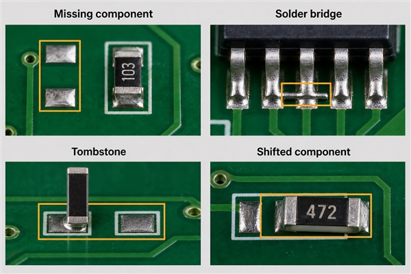
Assembly opens usually occur at the component-to-pad interface. Insufficient solder paste, blocked stencil apertures, poor wetting, oxidized terminations, lifted leads and incorrect reflow profiles can prevent a sound joint. A tombstoned chip component leaves one terminal disconnected. BGA and QFN packages can contain hidden opens that are not visible from the top of the board.

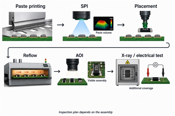
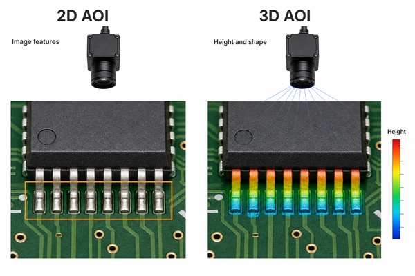
Paste-deposit control begins with an appropriate SMT stencil, aperture design and printing process. After placement and reflow, a complete PCB assembly inspection strategy can combine solder-paste inspection, AOI, X-ray and functional testing according to package type and fault coverage. None of these methods should be treated as universal: AOI can see many exposed joints, while X-ray is more useful for hidden structures and functional test verifies behavior through an exercised path.

What Are Common Open Circuit Examples?

A lamp connected through an open switch is the simplest example: source voltage exists, but the switch gap prevents current through the lamp. On a PCB, the same electrical condition can be less obvious because the break may be microscopic or buried inside a via, package or connector.

Example Open location Likely observation
Blown fuse Fuse element Downstream rail is absent; voltage may appear across the fuse
Cracked PCB trace Copper conductor One net loses continuity, sometimes only during flexing
Lifted IC lead Lead-to-pad joint A related input or output is inactive despite correct component placement
Open connector contact Mating interface or crimp Failure changes when the cable or connector is moved
Broken sensor wire Harness conductor Controller may report an open-circuit or out-of-range diagnostic code
Open via Plated barrel or internal pad connection Surface trace appears intact, but the net fails between layers

How Can You Find an Open Circuit With a Multimeter?

De-energize the board before using resistance or continuity mode. Disconnect external power, remove batteries when practical and discharge stored energy. Measuring resistance on a live circuit can damage the meter, the board or both. Also account for capacitors, inductors and parallel paths, which can make the reading change or create an alternate route around the suspected break.

Multimeter continuity test locating an open CCT on a PCB
  1. Use the schematic and layout to identify both endpoints of the target net.
  2. Confirm the meter and leads by touching the probes together; continuity should sound and resistance should be near the lead resistance.
  3. Probe the net endpoints. OL or no beep suggests an open, but component isolation may be required.
  4. Divide the path at accessible pads, vias, connector pins and component terminals.
  5. Retest progressively smaller sections until one segment changes from conductive to open.
  6. Inspect that segment under magnification and use controlled flexing or thermal stimulation only when investigating an intermittent fault.

In-circuit continuity readings can be misleading because resistors, semiconductor junctions, transformers and protection devices may create alternate paths. When the result conflicts with the schematic, disconnect one component terminal or isolate the branch. The detailed multimeter testing guide explains probe placement and mode selection for broader PCB checks.

What Should a Multimeter Read Across an Open Circuit?

In resistance or continuity mode on an unpowered and isolated path, a complete open normally produces OL, O.L, infinity or a value above the selected range. The exact display depends on the meter. OL can also mean that the probes are disconnected, the range is too low for the measured resistance or the selected mode is wrong, so first verify the instrument by shorting the probes.

In voltage mode on a powered circuit, the meter may show nearly the full supply across the open because the meter itself draws very little current. For example, one probe on the source side and one on the load side of a broken series path can reveal the voltage drop at the break. Use voltage-to-ground measurements on each side to understand which node remains connected to the source and which is held by the load or another network.

What Is Open Circuit Voltage?

Open circuit voltage, commonly written VOC, is the voltage measured at a source or network output when no external load current is drawn. A high-impedance voltmeter approximates this condition. Batteries, solar cells, power supplies and sensor outputs can all have a measurable VOC.

VOC is not necessarily the voltage available under load. Internal resistance, current limiting, weak connections and source chemistry can cause the terminal voltage to fall when current is drawn. A battery may therefore show a plausible open-circuit voltage yet fail to power the circuit. Measure both unloaded and appropriately loaded behavior when source condition is in doubt.

What Is the Difference Between an Open Circuit and a Closed Circuit?

A closed circuit provides a continuous path through which current can flow when a voltage source is present. An open circuit interrupts that path. The distinction describes connectivity, not whether a design is operating correctly: a correctly opened switch and a correctly closed relay can both represent normal states.

Condition Path continuity Ideal current Typical use or symptom
Open circuit Interrupted 0 A OFF switch, isolation or broken connection
Closed circuit Continuous Set by source and load Enabled branch or completed signal path

What Is the Difference Between an Open Circuit and a Short Circuit?

An open circuit has excessively high resistance in a path that should conduct. A short circuit has an unintended low-resistance connection between nodes that should remain separate. The resulting symptoms and risks differ sharply: an open stops the intended current, while a short can create excessive current, disturb signal levels or damage components.

Fault Electrical condition Common PCB causes Primary test
Open circuit Required path is discontinuous Broken trace, open via, lifted lead, poor joint Continuity and segmented voltage tracing
Short circuit Unwanted low-resistance path exists Solder bridge, copper bridge, debris, failed component Resistance-to-rail checks, current-limited power and thermal localization

Do not apply unrestricted power to a board suspected of having a short. Begin with unpowered resistance checks and use a current-limited supply only within the assembly’s safe limits. For an open, voltage tracing can be useful after unpowered continuity checks establish that energizing the board is safe.

How Do PCB Factories Detect Open Circuits?

Bare-board electrical test compares actual continuity and isolation against the manufacturing netlist. Flying-probe systems are flexible for prototypes and varied builds, while fixture-based universal electrical test is efficient when volume and design stability justify dedicated tooling. These tests can detect opens between accessible net points, but the test program and access strategy must cover the required nets.

Flying probe and optical inspection for PCB open circuit testing

Assembly inspection adds different layers of evidence. 3D SPI checks paste deposits before placement; AOI evaluates visible component and solder conditions; X-ray examines hidden joints and internal package features; functional testing confirms behavior through exercised paths. EBest Circuit (Best Technology) can combine flying-probe or universal bare-board electrical testing with 3D SPI, AOI, X-ray and functional testing according to net access, package type and assembly structure.

These methods are complementary. AOI cannot prove the electrical continuity of every buried connection, and a basic functional test may not activate every unused interface. Test coverage should therefore be mapped to the design’s critical nets and known failure mechanisms. The related PCB circuit opening guide provides a fabrication-focused discussion of hidden and intermittent defects.

How Can Open Circuit Defects Be Prevented?

Prevention starts by removing fragile geometries and uncontrolled interfaces. Maintain practical trace widths, annular rings and copper clearances for the selected fabrication class. Add teardrops or local reinforcement where justified, protect copper from panel stress, and keep mechanically loaded connectors away from unsupported board edges. Use appropriate strain relief for cables and ensure enclosure loads do not flex solder joints.

  • Follow validated trace, via and annular-ring rules instead of relying on minimum values everywhere.
  • Use netlist-based bare-board electrical test for production panels.
  • Design stencil apertures and reflow profiles around actual package terminations.
  • Provide accessible test points on critical rails, returns, buses and safety-related signals.
  • Support heavy connectors, switches and cables mechanically.
  • Control moisture, ionic contamination and corrosive exposure.
  • Use thermal cycling, vibration or flex testing when the service environment can drive intermittent opens.

For recurring failures, preserve the defective sample and identify the exact physical mechanism before changing multiple variables. A trace crack requires a different corrective action from a plating void, non-wetted lead or fretting connector. Process changes should be verified with the inspection method most capable of detecting that specific mechanism.

FAQ About Open CCT

Is an Open CCT Always Caused by a Broken Wire?

No. The open may be an intentional switch state or a fault in a fuse, PCB trace, via, solder joint, connector, component lead or internal component connection. The schematic and segmented continuity test identify which portion of the path is open.

Can an Open Circuit Be Intermittent?

Yes. Cracked solder joints, fatigued traces, damaged vias and worn connector contacts can change resistance with vibration, board flex or temperature. Logging the failure condition and testing under controlled stress can reveal a fault that disappears at room temperature on a stationary bench.

What Does Open CCT Mean in an Automotive Diagnostic Code?

It generally means the control module detects a missing electrical path or an out-of-range voltage consistent with an open circuit. The cause may be a broken harness conductor, disconnected plug, corroded terminal, failed load, poor ground or internal module fault. The exact test sequence must follow the vehicle wiring diagram and code definition.

Can a Board Pass Visual Inspection and Still Contain an Open Circuit?

Yes. A buried via crack, internal layer separation, hidden package joint or microscopic trace break may not be visible. Netlist electrical testing, X-ray, functional testing or sectional analysis may be required, depending on the suspected location.

Conclusion

Open cct means that an intended current path is interrupted. The most reliable diagnosis combines the schematic, safe continuity testing, voltage measurements at defined references and progressive isolation of the failed segment. In PCB production, netlist electrical test, paste inspection, AOI, X-ray and functional testing each address different open-circuit risks.

For PCB fabrication or PCBA support with test coverage matched to your board structure, contact EBest Circuit (Best Technology) at sales@bestpcbs.com.

You may also like

Standard Copper Busbar Sizes: A Buyer’s Selection Guide

August 17th, 2026

Standard copper busbar sizes can shorten sourcing time, but width and thickness alone do not make a part safe or ready to build. If material, current conditions, hole pattern, finish, and tolerances are unclear, the result may be overheating, poor terminal alignment, enclosure interference, or a quotation based on the wrong part.

This matters when the busbar connects to a PCB, terminals, or an assembled power module. A small dimension change can affect mounting holes, clearances, tool access, and the assembly sequence. If you send us the released busbar drawing and PCB files, the EBest Circuit (Best Technology) team can review the manufacturing interfaces together, point out missing quotation details, and help you define a practical PCB/PCBA, inspection, and testing scope. Your engineers keep control of the electrical design and final approval; our role is to make the handoff easier and reduce avoidable surprises before production.

Standard copper busbar sizes

Standard Copper Busbar Sizes in mm and Inches

There is no single worldwide list of standard copper busbar sizes. In practice, “standard” usually means a size regularly stocked by a mill, distributor, or fabricator. Availability varies by region, copper grade, temper, length, quantity, and supplier.

Metric tables commonly show width × thickness, such as 40 × 5 mm. North American tables may show thickness × width, such as 1/4 × 2 in. Always label both dimensions and units on the drawing; an unlabeled pair can be reversed during quotation or manufacturing.

Common reference thicknesses include:

  • Metric: 3, 5, 6, 8, and 10 mm.
  • Imperial: 1/16, 1/8, 3/16, 1/4, 3/8, and 1/2 in.
  • Larger or unusual combinations may require plate cutting or a custom material order.

ASTM B187/B187M covers requirements for copper bar, bus bar, rod, and shapes and lists several copper UNS designations for electrical applications. It is a material specification, not a universal stock catalogue. The purchase order and released drawing still need the copper grade, dimensions, tolerances, finish, and any certificate requirements.

Buyer check: Confirm the exact stock form with the proposed supplier before freezing the design. A size shown online may not be available in the required grade, length, or quantity.

Standard Copper Busbar Sizes Chart

This chart is a dimensional reference, not an ampacity table. The combinations are common examples, but they are not a promise of supplier availability.

Nominal width × thickness Cross-sectional area Approximate inch equivalent Confirm before release
20 × 3 mm 60 mm² 0.787 × 0.118 in. Grade, length, cutting tolerance
25 × 3 mm 75 mm² 0.984 × 0.118 in. Width/thickness order
30 × 3 mm 90 mm² 1.181 × 0.118 in. Edge condition and flatness
40 × 5 mm 200 mm² 1.575 × 0.197 in. Hole clearance and bends
50 × 5 mm 250 mm² 1.969 × 0.197 in. Finish and contact areas
60 × 5 mm 300 mm² 2.362 × 0.197 in. Length and assembly envelope
80 × 10 mm 800 mm² 3.150 × 0.394 in. Support, hardware, tooling
100 × 10 mm 1,000 mm² 3.937 × 0.394 in. Enclosure space and tolerances

Cross-sectional area equals width multiplied by thickness, but equal area does not guarantee equal performance. Shape also affects surface area, stiffness, bending, connection geometry, AC effects, and heat dissipation.

Do not silently replace a metric size with the nearest inch fraction. For example, 5 mm and 3/16 in. are close but not identical. The difference can affect holes, bends, stack height, terminal alignment, and clearances. Record every approved alternative on the controlled drawing.

How to Select Busbar Size?

Start with the customer’s validated electrical and mechanical requirements, then compare those requirements with real stock availability.

Electrical inputs:

  • Continuous, peak, and fault current.
  • AC frequency or DC operation.
  • Ambient temperature and permitted temperature rise.
  • Enclosure, ventilation, bar spacing, orientation, and parallel bars.
  • Joint design, plating, allowed voltage drop, and protection strategy.

Mechanical and integration inputs:

  • Space around the PCB, terminals, enclosure, and other conductors.
  • Holes, slots, bends, datums, and critical tolerances.
  • Supports, vibration, weight, and installation sequence.
  • Finish, masking, insulation, and contact areas.

If a stocked size meets the released requirements, it may reduce lead time and waste. If it does not, use a controlled custom route instead of weakening clearances, joints, or mechanical requirements to fit a catalogue bar.

Standard copper busbar sizes

How Copper Busbar Size and Current Rating Relate

Copper busbar size and current rating are related, but there is no universal conversion from cross-sectional area to allowable current. A published value is valid only under its stated conditions.

The Copper Development Association’s rectangular-busbar data shows that temperature rise, surface emissivity, number of bars, spacing, and configuration can change ampacity. Enclosure and ventilation conditions also influence temperature rise. A bare bar in open air should not inherit the same current rating when it is enclosed, coated, stacked, or connected through poorly controlled joints.

Before accepting a current value, confirm:

  • The source table, standard, calculation, or test report.
  • Copper grade, dimensions, orientation, and surface condition.
  • Ambient temperature and permitted temperature rise.
  • AC/DC conditions, frequency, spacing, parallel bars, and enclosure.
  • Joint design, terminal limits, protection, and validation method.

A size chart can narrow the options; it cannot approve the final conductor. The customer releases the rating and acceptance criteria. A useful manufacturing review then checks whether the received drawing, PCB interface, controlled dimensions, and proposed inspection or test evidence agree with that release.

Copper Bus Bar Stock or Custom Size?

Standard copper bus bar stock can reduce sourcing time when its grade, dimensions, and tolerances match the released part. A custom route is more suitable when the approved envelope, terminal geometry, bends, hole pattern, or current path cannot be met without risky substitutions.

Use stock when:

  • The exact grade, condition, length, and certificates are available.
  • Dimensions and tolerances meet the drawing.
  • Cutting, drilling, forming, and finishing have enough process margin.
  • The size does not force changes to clearances, joints, or enclosure space.

Consider custom material or fabrication when:

  • Stock would create excessive machining or waste.
  • A special thickness, profile, bend, or controlled edge is required.
  • Hole patterns and interfaces have little tolerance with the nearest stock size.
  • Validation depends on the exact released cross-section.

Project example: A buyer selects a 50 × 5 mm bar because its 250 mm² area fits an early calculation. During integration review, it blocks connector tool access and leaves too little space around an offset terminal. Changing to a narrower, thicker bar may solve the space problem but alter bending, cooling, and joint geometry. The safer next step is to compare validated options, update the mechanical stack, and release one controlled drawing before quotation.

Why integrated review matters: A busbar and PCB can each pass an isolated drawing check and still fail together. Hole patterns must align; bends and thickness must fit the enclosure; contact areas must match the assembly process; and installers need access for hardware, soldering, inspection, and rework.

How EBest Circuit supports the handoff: Our team can review the released busbar and PCB manufacturing interfaces in one quotation package, then connect that review with PCB fabrication, component-sourcing support, PCBA, inspection planning, and agreed testing coordination. We will flag unclear inputs and state the proposed scope instead of quietly making design assumptions. This gives your team a clearer decision record while electrical design, system safety, and final approval remain under your control.

Send these RFQ files:

  • Released 2D drawing and a matching 3D model when the part is formed.
  • Material, finish, masking, certificate, and quantity requirements.
  • Critical dimensions, datums, tolerances, and inspection expectations.
  • Customer-approved ratings, test inputs, and acceptance limits.
  • PCB files, BOM, assembly interfaces, revision, and delivery target.

Send the controlled package, not a screenshot of a size table. Email the files and required scope to sales@bestpcbs.com; our team will review what is ready, identify what still needs confirmation, and help you define the next manufacturing step.

North American Charging Equipment PCB and Busbar Project

Standard copper busbar sizes

A North American customer needed 500 PCBs for charging equipment within a one-week lead time. EBest Circuit manufactured and delivered the order to these released PCB requirements:

  • 2-layer FR-4 with Tg 130°C.
  • 1 oz finished copper and 1.6 mm finished board thickness.
  • Green solder mask and white silkscreen.
  • HASL surface finish.
  • Routed and delivered as individual boards rather than panels.

The board was used in a charging-equipment assembly with a rectangular copper busbar interface. The customer’s drawings controlled the busbar width, thickness, copper grade, finish, and current rating; the PCB’s 1 oz copper was not treated as the main current path.

To meet the one-week schedule, our team checked the PCB stack-up, drill and outline data, individual-board routing, busbar mounting holes, terminal geometry, electrical clearances, and fastener access under one revision. The 500 boards were fabricated, routed, inspected, and packed as individual pieces.

This case shows the value of sending the PCB files and controlled busbar drawing together. EBest Circuit can review the interfaces, produce the PCB, and support sourcing and PCBA when required, while the customer retains control of electrical ratings and final design approval.

FAQs About Standard Copper Busbar Sizes

Is there one universal list of standard copper busbar sizes?

No. “Standard” usually reflects recurring supplier stock. Available combinations differ by region, grade, thickness, temper, and quantity, so confirm availability before release.

Should dimensions be written as width × thickness?

Metric tables often use width × thickness, while some imperial references list thickness × width. Label the dimensions and units on the drawing to prevent reversal.

Can two bars with the same cross-sectional area carry the same current?

Not automatically. Shape, orientation, enclosure, temperature rise, spacing, joints, and surface condition can change performance. Validate the actual assembly.

Is C11000 the only copper grade used for busbars?

No. C11000 is common, but ASTM B187/B187M lists several copper UNS designations for electrical applications. Specify the required grade or approved alternatives.

What should be sent with a copper busbar RFQ?

Send the released drawing, material and finish, quantities, tolerances, inspection needs, approved ratings, assembly interfaces, revision, and delivery target.

If your busbar must align with a PCB, terminals, enclosure, or power assembly, we would be glad to look at the manufacturing package with you. Send the released files, BOM, quantities, and acceptance requirements to sales@bestpcbs.com. The EBest Circuit (Best Technology) team will point out missing quotation inputs and help define a practical PCB/PCBA, inspection, and agreed testing scope before production.

Use this guide to review Standard copper busbar sizes, then send your released PCB, busbar, BOM, quantity, and acceptance requirements to sales@bestpcbs.com.

You may also like

How to Wire a Potentiometer? 3-Pin Diagram and PCB Guide

August 17th, 2026

Learning how to wire a potentiometer starts with identifying its two fixed end terminals and movable wiper. A three-wire connection produces an adjustable voltage; a two-wire connection produces an adjustable resistance. The correct choice depends on the circuit function, the potentiometer datasheet, the signal level and the load connected after the wiper.

How to wire a potentiometer with three terminals and a PCB

What Is a Potentiometer and How Does It Work?

A potentiometer is a three-terminal variable resistor. A resistive track runs between the two end terminals, while a movable contact called the wiper travels along that track. Rotating a shaft, moving a slider or turning a trimmer screw changes the resistance from the wiper to each end. The resistance between both end terminals remains approximately equal to the component’s rated value.

There are two basic operating modes. In voltage-divider mode, the circuit uses all three terminals and takes an adjustable output from the wiper. In rheostat mode, the circuit uses the wiper and one end terminal as a two-terminal variable resistance. The component itself has no fixed positive or negative polarity, but the chosen end-terminal connections determine whether clockwise rotation raises or lowers the output.

What Are the Three Wires on a Potentiometer?

The three connections represent two ends of one resistive element and one moving tap. Pin numbers and viewing direction are not universal across every rotary, slide, panel-mount and PCB trimmer package, so use the selected part’s datasheet instead of assuming that a terminal is ground simply because it appears on the left.

Terminal Electrical function Typical voltage-divider connection What a meter should show
End terminal A One end of the fixed resistive track VREF or VIN Fixed total resistance to end B
Wiper Movable contact on the track VOUT or ADC input Resistance changes to either end as the shaft moves
End terminal B Opposite end of the fixed resistive track GND or signal return Fixed total resistance to end A

Some potentiometers also have metal mounting tabs, a body ground terminal, an integrated switch or multiple gangs. These extra connections are not part of the basic three-terminal resistive element. Treat them according to the package drawing and schematic, not by physical resemblance.

How Do You Identify the Wiper and End Terminals?

Disconnect the component from power and, where possible, test it outside the circuit. Set a multimeter to resistance mode. The pair that reads approximately the rated resistance and barely changes as the shaft turns identifies the two end terminals. The remaining terminal is the wiper.

Potentiometer pinout and wiper identification with a multimeter

Next, measure between the wiper and either end. The reading should change smoothly from near the contact resistance toward the total resistance. Repeat the measurement from the wiper to the other end; one reading should rise while the other falls. Intermittent jumps, open readings or dead regions can indicate contamination, a damaged track, a worn wiper or unreliable probe contact.

Physical pin 2 is often the wiper on common three-pin rotary parts, but that convention is not sufficient for production documentation. Confirm the terminal numbering, top-view or bottom-view orientation, footprint pad mapping and shaft rotation direction from the exact manufacturer datasheet.

How to Wire a Potentiometer as a Voltage Divider?

Connect one fixed end to the upper reference voltage, connect the opposite end to the return or ground reference, and connect the wiper to the high-impedance input that requires an adjustable voltage. With an unloaded linear potentiometer, the wiper voltage follows its fractional position along the resistive track.

Potentiometer voltage divider and variable resistor wiring comparison

The ideal relationship is VOUT = VIN × RLOW / RTOTAL, where RLOW is the resistance from the wiper to the ground-side terminal. The connected load must be much higher than the potentiometer’s output resistance, or it will change the divider ratio. A buffer amplifier is appropriate when the next stage draws enough current to disturb the setting.

  1. Verify the maximum voltage across the two end terminals.
  2. Connect the reference and return to the two fixed ends.
  3. Connect the wiper to the receiving circuit, not directly to a high-current load.
  4. Power the circuit and measure the wiper at both rotation limits before connecting sensitive downstream hardware.
  5. Swap the two end connections if the control direction is opposite to the intended user action.

How to Wire a Potentiometer as a Variable Resistor?

For rheostat operation, place the wiper and one end terminal in series with the circuit. Resistance between those two terminals changes with shaft position. The other end can remain open, but connecting it to the wiper is a common reliability measure: if the moving contact becomes momentarily intermittent, the circuit retains a path through the remaining track instead of depending only on an open wiper contact.

Check the track power rating and maximum wiper current. Using only part of the resistive element does not allow the full rated power to be concentrated into that shorter section. A small panel potentiometer is normally intended for signal control, calibration or bias adjustment, not direct motor, heater, lamp or speaker current. Add a fixed series resistor when the adjustment could otherwise reach an unsafe near-zero resistance.

Does It Matter Which Way a Potentiometer Goes?

Electrically, the two end terminals are interchangeable. Reversing them reverses the relationship between shaft direction and wiper voltage. For a front-panel level control, designers usually expect clockwise rotation to increase the value. Verify that behavior from the actual shaft side because a rear-view terminal drawing can make clockwise and counterclockwise labels appear reversed.

The wiper is not interchangeable with an end terminal. If the circuit takes its output from an end instead of the wiper, rotation will not create the intended adjustable voltage. A schematic should label the nets by function, such as VREF, POT_WIPER and AGND, while the footprint and assembly drawing preserve the manufacturer’s pin numbers.

How to Wire a Potentiometer to an Arduino or MCU ADC?

Use the potentiometer as a voltage divider: connect the two ends to the ADC reference supply and its associated ground, then connect the wiper to an analog input. This keeps the wiper within the permitted ADC input range as long as the reference connections and device limits are correct.

Potentiometer wiper connected to a microcontroller ADC with an RC filter

The total resistance must satisfy both loading and ADC acquisition requirements. A lower value draws more continuous current across the reference. A very high value reduces that current but raises source impedance, which can prevent the ADC sample capacitor from settling within its acquisition time. Many general control interfaces use a value around 10 kΩ, but the correct limit comes from the MCU datasheet and sampling configuration.

When readings are noisy, place a small RC filter close to the ADC input, keep the wiper route short, and return the potentiometer ground to the quiet analog reference area. The series resistance, capacitor and sampling rate must be selected together so that filtering does not make the control unacceptably slow. Software averaging can reduce random variation, but it cannot repair a floating ground, worn track or incorrect pin mapping.

How to Wire a Potentiometer for Volume Control?

For a basic single-channel passive volume control, connect the audio source to one end terminal, signal ground to the opposite end, and the wiper to the amplifier input. This attenuates the source before amplification. Swapping the two end terminals reverses the direction of level change.

Audio controls commonly use a logarithmic or audio taper because human loudness perception is not linear. Confirm the taper code from the datasheet; letter conventions can differ by manufacturer or region. The potentiometer value must work with the source impedance, amplifier input impedance and coupling capacitors so it does not cause excessive loading, bass roll-off or noise pickup. Stereo audio requires a dual-gang part with matched sections, not two unrelated single controls.

How to Wire a Potentiometer to Control Motor Speed?

Do not place a low-power signal potentiometer directly in series with a motor unless both its current and power ratings explicitly support that load. Motor current, startup surge and inductive transients can overheat the resistive track or damage the wiper.

Instead, wire the potentiometer as a voltage divider that feeds the control input of a PWM motor controller, driver IC, VFD analog input or microcontroller ADC. For a VFD, verify the specified reference voltage, analog-input impedance, common terminal and shielding instructions. For a DC motor driver, keep the low-level wiper signal away from switched motor currents and provide the required common reference or isolation.

How Do You Choose Resistance, Taper, and Power Rating?

Selection begins with the electrical function, then the receiving circuit and mechanical package. The table summarizes the decision points without assuming one universal value.

Parameter Choose based on Practical check
Total resistance Allowed reference current, source loading and input impedance Confirm ADC acquisition or amplifier loading at worst case
Taper Linear control, audio perception or a specified custom response Read the manufacturer curve and taper code
Power rating Voltage across the track and used track length Calculate dissipation and apply datasheet derating
Wiper current Current taken by the connected node Do not treat the wiper as a load-power terminal
Rotation and life User travel, adjustment resolution and operating cycles Check electrical angle, mechanical angle and rotational life
Environmental sealing Dust, moisture, cleaning, vibration and temperature Select open, dust-resistant or sealed construction as required

A multi-turn trimmer improves adjustment resolution for calibration but is slower to set. A panel-mount rotary control provides direct user access, while an SMD or through-hole trimmer is intended for board-level adjustment. Dual-gang and switched potentiometers add terminals and require a matching symbol and footprint rather than a generic three-pin library part.

How Should a Potentiometer Be Mounted on a PCB?

Use the manufacturer’s recommended footprint and verify whether the drawing is a top view or bottom view. Match pin pitch, finished-hole diameter, pad size, solder-mask opening, body courtyard, shaft position and mechanical mounting tabs. A front-panel control should transfer user torque to a panel bushing, bracket or support tabs instead of relying only on three solder joints.

PCB potentiometer footprint with three pins support tabs and wiper routing

For conventional control boards, FR4 PCB manufacturing can support through-hole panel controls, SMD trimmers and mixed component layouts. Place the control near the board edge when the shaft must pass through an enclosure, but keep adequate copper clearance from mounting hardware and define a shaft or knob keepout in the mechanical model.

An SMD trimmer needs paste apertures and pad geometry matched to its termination design. The SMT stencil should deposit enough solder for stable joints without allowing the part to float or tilt during reflow. Through-hole units require adequate annular rings, lead protrusion control and a soldering process compatible with the body temperature limit.

What PCB Layout Rules Reduce Potentiometer Noise?

Route the wiper as a sensitive analog signal. Keep it short, avoid parallel runs beside clocks, switch nodes and motor phases, and provide a continuous reference path beneath it when the stack-up allows. Connect the ground-side terminal to the same analog reference used by the receiving circuit rather than to a distant noisy return.

  • Place any RC filter at the receiving ADC or amplifier input.
  • Keep high-current load returns out of the potentiometer ground path.
  • Use twisted or shielded cable for a remote panel control when cable length and environment require it.
  • Connect a metal case or shield only according to the product and chassis-ground plan.
  • Add connector pin labels and test points for VREF, WIPER and GND when service access is needed.
  • Define ESD protection when the shaft, knob or remote wiring can expose the interface to user discharge.

EBest Circuit (Best Technology) supports SMT, THT and mixed PCB assembly. Depending on the design risk, inspection can combine 3D SPI, AOI, X-ray, functional testing and final inspection. For a potentiometer interface, a functional test should verify endpoint voltage, smooth travel, direction, channel tracking where applicable and the absence of intermittent output.

How to Test a 3-Wire Potentiometer?

Begin with power removed. Measure between the two end terminals and compare the reading with the marked or specified total resistance. Then measure from the wiper to each end while moving the control through its full travel. The readings should change smoothly in opposite directions and should approximately sum to the total resistance, allowing for contact resistance and tolerance.

After wiring, power the circuit with a current-limited supply. Measure the two reference endpoints, then sweep the wiper and confirm that its voltage remains within the expected range. Check the intended direction, endpoint margin and stability at several positions. The related multimeter guide explains safe voltage, resistance and continuity measurements; never use resistance mode on an energized circuit.

What Potentiometer Wiring Mistakes Cause Reversed or Noisy Output?

Symptoms are easier to diagnose when each failure is tied to a specific connection or physical condition.

Symptom Likely cause Corrective action
Control works backward End terminals are reversed Swap the two fixed-end connections
Output is fixed at one rail Wiper mapped to the wrong pad or shorted Verify symbol-to-footprint pin mapping and solder bridges
Output floats or jumps Open wiper, missing reference, worn track or poor joint Check continuity, resolder and replace a damaged part
ADC value is unstable High source impedance, noisy ground or long wiper trace Review ADC acquisition time, grounding and local filtering
Audio crackles DC on the wiper, contamination or contact wear Review coupling, clean only with an approved method or replace the control
Part overheats Excessive track power or wiper current Recalculate dissipation and use a driver or higher-rated component

The earlier potentiometer wiring guide provides a broader comparison of common wiring configurations. For production hardware, the schematic, footprint, BOM, assembly drawing and test limits must all identify the same terminal numbering and intended rotation.

FAQ About How to Wire a Potentiometer

Can a potentiometer be wired on a breadboard?

Yes. Insert the three electrical pins into separate connected rows, then jumper the two ends to the reference and ground and the wiper to the measured node. Some panel potentiometers have terminals that do not fit a breadboard and need short wires or an adapter PCB.

Can the wiper be connected to either end terminal?

For two-terminal variable-resistor operation, the wiper can work with either end. The chosen end determines whether resistance rises or falls with rotation. Tying the unused end to the wiper can retain a resistive path if wiper contact becomes intermittent.

Can a potentiometer connect directly to a speaker?

A small signal potentiometer is generally unsuitable for direct speaker power. Use it at a high-impedance amplifier input as a volume-control divider, or use a purpose-rated attenuator designed for the speaker impedance and power.

Why does the output not reach exactly zero or the full reference?

Wiper contact resistance, mechanical end stops, loading, protection resistors and ADC reference limits can prevent ideal rail-to-rail travel. Use measured endpoint limits in firmware or calibration rather than assuming perfect 0% and 100% values.

Is a potentiometer the same as a rheostat?

A potentiometer has three accessible terminals and is normally used as a voltage divider. When its wiper and one end are used as two terminals, it performs the variable-resistance function commonly called a rheostat. Power rheostats are often constructed and rated differently from small signal potentiometers.

Conclusion

The practical method for how to wire a potentiometer is to identify the two fixed ends and wiper first, choose voltage-divider or variable-resistor mode, verify direction and power limits, and test the complete interface before relying on it. PCB-mounted controls also need correct footprint orientation, mechanical support, quiet routing and a testable reference path.

EBest Circuit (Best Technology) can support PCB fabrication, SMT/THT assembly and functional verification for control interfaces that use rotary, slide or trimmer potentiometers. For technical communication about a PCB or PCBA design, contact sales@bestpcbs.com.

You may also like

Copper Thermal Conductivity vs Temperature for PCB Design

August 17th, 2026

Copper thermal conductivity vs temperature data can look precise while still producing the wrong PCB decision. The commonly quoted room-temperature value describes bulk copper under defined conditions; it does not automatically represent a finished board, a plated feature, or the complete component-to-cooler heat path.

PCB buyers therefore need to confirm the copper temperature and condition, the released stackup and heat-spreading geometry, and the drawings, fabrication limits, and test inputs required before production. This guide turns reference conductivity data into concise, manufacturable PCB checks.

Copper thermal conductivity vs temperature
Copper thermal conductivity vs temperature review at a PCB thermal-analysis bench.

Copper Thermal Conductivity vs Temperature Chart

Copper is often assigned a single thermal conductivity value, but that shortcut can mislead a PCB thermal review. The value depends on temperature, material condition, and purity. It also describes bulk copper—not the effective thermal conductivity of a finished multilayer board.

The table below is a practical reference for pure copper from 100 K to 1,200 K. It shows the expected downward trend as temperature rises through the range relevant to many industrial calculations.

Temperature (K)Approx. temperature (°C)Thermal conductivity k (W/m·K)
100-173480
150-123429
200-73413
250-23406
30027401
400127393
600327379
800527366
1,000727352
1,200927339

For an ordinary PCB operating near room temperature, 401 W/m·K is a reasonable first-pass value for bulk copper. For a high-temperature calculation, use a value matched to the expected copper temperature—not the ambient air temperature—and retain margin for interfaces and manufacturing variation.

Copper Thermal Conductivity Temperature Dependence Explained

In copper, mobile electrons carry most of the heat. As temperature rises, atomic vibrations increase and scatter those electrons more frequently. The result is lower thermal conductivity across the normal and elevated-temperature range.

The behavior is not one simple straight line across every temperature. At cryogenic temperatures, conductivity can rise sharply to a peak and then fall again near absolute zero. The peak is highly sensitive to purity and defects, so a room-temperature copper value cannot be extended into a cryogenic model.

  • Temperature range: State the minimum, normal, and maximum copper temperature used in the calculation.
  • Copper condition: Identify the relevant copper grade, temper, plating, and any alloyed or bonded layers.
  • Heat-flow direction: Separate in-plane spreading through copper from through-board heat flow across dielectric layers.
  • Boundary conditions: Define the heat source, contact area, cooling interface, airflow, and allowed temperature rise.

A useful supplier question is not only “What is copper’s k value?” It is “Which value and temperature range were used in the thermal model, and does the released stackup support that heat path?”

Thermal Conductivity of Copper at Various Temperatures

Published datasets agree on the broad room-to-high-temperature trend: copper is near 400 W/m·K around room temperature and gradually declines as temperature rises. One Zenodo dataset lists 401 W/m·K at 273 K, 398 W/m·K at 300 K, 392 W/m·K at 400 K, and 383 W/m·K at 600 K.

Cryogenic data require more care. NIST publishes OFHC copper curve fits from 4 K to 300 K for several residual resistance ratio (RRR) values. RRR is a practical indicator of purity and defect scattering; higher-RRR copper can reach a much larger low-temperature conductivity peak than ordinary copper.

  • Room and elevated temperatures: Use a temperature-matched value and document the source.
  • Cryogenic service: Specify the copper grade and an appropriate RRR assumption or material certificate.
  • Wide operating range: Use a curve or temperature bands instead of one constant value.
  • Production release: Keep the thermal-model assumption aligned with the copper actually purchased and fabricated.

For PCB purchasing, do not request “high-purity copper” as an undefined phrase. Put the required copper specification, thickness, finished-copper tolerance, surface finish, and any evidence requirement into the drawing or procurement package.

What Is the Thermal Conductivity of Copper at Room Temperature?

At approximately 20-27°C, pure copper is commonly treated as about 400-401 W/m·K. That number is useful for material comparison and early thermal estimates, but it should not be copied directly into a board-level claim.

A PCB contains copper foils, plated holes, resin, glass reinforcement, solder mask, surface finish, solder, components, and interfaces. The copper may spread heat efficiently along the plane of a layer, while through-thickness heat transfer is restricted by dielectric materials and small contact areas.

  • Use 401 W/m·K: For a documented first-pass bulk-copper estimate near room temperature.
  • Use a lower temperature-specific value: When copper operates well above room temperature.
  • Use effective PCB properties: When modeling the complete stackup or through-board heat flow.
  • Use test correlation: When temperature limits are tight, interfaces dominate, or safety/reliability depends on the prediction.

Before RFQ, the customer should identify whether the value applies to raw copper, a copper feature, one PCB layer, or the assembled thermal path. This prevents a material constant from becoming an unsupported finished-product requirement.

Copper Conductivity vs Temperature for PCB Heat Spreading

Temperature-dependent copper conductivity matters, but geometry usually controls whether the available copper can move enough heat. A thin trace and a wide copper plane can use the same material value while producing very different temperature rises.

  • Copper thickness and area: Confirm base copper, finished copper, plating contribution, plane coverage, neck-downs, and current/heat bottlenecks.
  • Layer location: Identify whether the principal heat-spreading layer is external or buried and what dielectric separates it from the source.
  • Thermal vias: Define finished hole size, plating, quantity, pitch, fill/cap requirements, and the receiving copper area.
  • Interfaces: Include solder joints, thermal pads, dielectric layers, coatings, mounting pressure, and contact resistance in the model.
  • Manufacturing tolerances: Review whether minimum feature sizes, annular rings, registration, copper balance, and finished thickness can support the proposed heat path.

EBest Circuit (Best Technology) can review the released PCB data for manufacturability, stackup, copper distribution, via structures, fabrication, assembly, inspection, and test coordination. The customer remains responsible for system heat loads, component junction limits, airflow, enclosure cooling, and final product validation unless a separate scope is agreed.

Copper thermal conductivity vs temperature
PCB copper heat-spreading measurement with probes and thermal imaging.

Copper Thermal Conductivity vs Aluminum for PCB Tradeoffs

At room temperature, copper conducts heat substantially better than aluminum: approximately 401 W/m·K versus about 237 W/m·K for pure aluminum. Copper can therefore move more heat through the same idealized cross-section, but conductivity alone does not select the best PCB construction.

Decision factorCopperAluminum-base option
Thermal conductivityAbout 401 W/m·KAbout 237 W/m·K
WeightHeavierLighter
PCB roleFoil, planes, and viasMetal-core base
Buyer checkCopper geometryDielectric and base

Choose the construction by the complete heat path, electrical isolation, weight, mechanical needs, achievable geometry, cost, and validation plan. A copper-heavy FR-4 board, an MCPCB, and a ceramic PCB solve different constraints; none should be selected from one W/m·K number alone.

PCB Project Example: Copper Thermal Conductivity in Heat-Spreading Checks

In one customer order, EBest Circuit reviewed a compact 47 × 34.5 mm, 12-layer FR-4 TG180 PCB built to IPC Class 3. The build combined blind vias from L1-L2 and L12-L11, buried vias from L2-L11, resin-plugged and plated-flat vias, a 2.0 mm finished thickness, and ENIG. Before production, the customer required the production stackup and CAM artwork for approval.

The thermal and manufacturing concern was not selecting another handbook conductivity value. The order data did not confirm the proposed 1 oz outer copper, while the residual copper area differed significantly among layers. Those details affect the real heat-spreading geometry, copper balance, and buildability even though bulk copper near room temperature remains about 401 W/m·K.

  • Outer-copper clarification: The customer had not confirmed 1 oz outer copper. EBest Circuit therefore kept it open in the EQ and production stackup instead of treating it as an approved input.
  • Via feasibility: The blind/buried sequence and resin-plugged, plated-flat vias required manufacturing review. The customer retained a ±2 mil via tolerance, so the released drawing and inspection basis had to preserve that decision.
  • Test-coupon confirmation: The COC mentioned a test coupon, but this order did not include impedance control. The customer confirmed that no coupon was needed, so the production documents were aligned with the agreed scope.
  • Copper balance decision: Because residual copper differed substantially by layer, engineering recommended a 1.0% bow-and-twist control. The customer did not accept the recommendation, so the decision was recorded and the production data remained customer-controlled.
  • Release gate: EBest Circuit issued the production stackup and CAM artwork for customer approval. Production could begin only after those documents were confirmed.

This order shows why copper thermal conductivity must be checked together with the actual stackup and released copper geometry. The credible supplier action was to surface unresolved data, preserve the customer's decisions, and gate production on approved manufacturing documents—not to claim that the 401 W/m·K material value alone guaranteed board temperature.

Copper thermal conductivity vs temperature
Production stackup and CAM review before releasing a 12-layer PCB order.

Copper Thermal Conductivity vs Temperature FAQs

Does copper thermal conductivity decrease as temperature increases?

Across typical room and elevated-temperature ranges, yes. Reference tables show a gradual decline as temperature rises. Cryogenic behavior is different and depends strongly on purity and RRR.

What copper thermal conductivity value should I use at room temperature?

About 400-401 W/m·K is a common bulk-copper reference near 20-27°C. State the source and do not treat it as the effective conductivity of the complete PCB.

Can I use one copper conductivity value for the full PCB temperature range?

Only for a rough model over a narrow range with adequate margin. For wide or critical ranges, use temperature-dependent data or defined temperature bands and correlate the model with testing.

Does thicker copper automatically solve a PCB hotspot?

No. Thickness can help, but plane area, bottlenecks, layer position, vias, dielectric interfaces, component attachment, and cooling boundary conditions also control the result.

What should I send for a PCB thermal and DFM review?

Send the controlled fabrication data, stackup, finished-copper requirements, drill data, BOM and placement data for assembly, expected operating range, heat-source information, thermal-interface assumptions, and the temperatures or test points that must be verified.

For a copper thermal conductivity vs temperature manufacturability review, contact EBest Circuit (Best Technology) at sales@bestpcbs.com with the controlled board package and operating assumptions. The review can then focus on the files, tolerances, heat-spreading features, and verification inputs that affect fabrication and assembly risk.

You may also like

USB Motherboard Pinout: Header Types and PCB Checks

August 17th, 2026

USB motherboard pinout errors can damage a port, prevent device enumeration, or force a board respin. Common causes include a reversed connector view, incorrect footprint, swapped differential pair, missing protection, or an uncontrolled assembly drawing.

This guide compares common internal USB headers and the checks needed before PCB fabrication and assembly. Always follow the released motherboard manual, connector drawing, USB specification, and customer-approved electrical design.

USB motherboard pinout
A keyed internal USB motherboard header checked before PCB fabrication and assembly.

What a USB Motherboard Pinout Shows

A USB motherboard pinout maps each header position to power, ground, USB 2.0 data, SuperSpeed pairs, sideband, shield, key, or no-connect functions.

Confirm the drawing view before comparing signals. Pin 1, row numbering, key position, and latch direction must agree across the schematic, footprint, assembly drawing, cable drawing, and inspection record.

Before approving a pinout, confirm four things:

  • The exact connector part number and its manufacturer drawing.
  • The viewing direction used by every pin-number diagram.
  • The signal-to-pin mapping in the released schematic and netlist.
  • The mating cable or front-panel assembly, including any proprietary wiring.

Matching pin counts do not prove matching assignments. OEM and custom boards may use proprietary keying or pin maps.

USB Motherboard Connector Types

USB generation and mechanical header type are separate decisions. USB 2.0, USB 3.x, and front-panel Type-C headers use different connectors and signal sets.

Header typeTypical formMain signalsBuyer check
USB 2.0 internal header2 x 5 positions, commonly one key/missing pinTwo USB 2.0 ports: power, D-, D+, groundConfirm key position and whether pin 10 is NC, shield, or overcurrent-related.
USB 3.x front-panel headerShrouded 19/20-position familyUSB 2.0 lines plus SuperSpeed TX/RX pairs, power, groundConfirm connector revision, pair polarity, pair naming, and mating cable.
Front-panel USB Type-C headerCompact Type-E/Key-A style familyHigh-speed lanes and control/sideband functions depend on implementationConfirm the exact standard revision, connector drawing, orientation, and controller architecture.

An adapter may solve a mechanical mismatch, but it does not confirm bandwidth, power, controller support, or pin assignment.

USB 2.0 Header Pinout and Keying

A common USB 2.0 header serves two ports, each using +5 V, D-, D+, and ground. A missing pin or blocked cavity provides keying; the remaining position may be NC, shield, or overcurrent-related.

An incorrect USB 2.0 connection can cause several different outcomes:

  • VBUS applied to a data or ground position can damage the port or connected device.
  • D+ and D- swapped within a port can prevent enumeration or create intermittent behavior.
  • A connector installed in the wrong orientation can defeat the intended protection of the missing key pin.

For a new PCB, verify pin 1, key location, footprint orientation, courtyard, housing clearance, solder mask, and assembly notes. For an existing board, use its exact manual and revision.

USB 3.0 Header Signals and Pair Routing

A USB 3.0 front-panel header combines USB 2.0 signals with SuperSpeed TX/RX pairs, power, ground, and shield or drain connections. More signals make routing and documentation errors more costly.

TX/RX labels can appear reversed when drawings describe opposite sides of the interface. Confirm the naming convention and connector view before changing net names.

PCB review should cover:

  • Differential-pair membership and polarity.
  • Impedance, reference planes, layer transitions, and return paths.
  • Skew, pair spacing, via stubs, pads, and test-point discontinuities.
  • Connector placement and cable-bend clearance.
  • Customer-approved VBUS protection, grounding, shielding, and ESD parts.

EBest Circuit (Best Technology) can review the released PCB data for manufacturability and coordinate fabrication, component sourcing, PCBA, inspection, and agreed testing inputs. The customer remains responsible for USB topology, controller selection, electrical targets, firmware, compliance, and final system validation.

USB motherboard pinout
PCB layout review helps confirm differential-pair routing and connector integration.

USB Type C Header Integration Risks

For a front-panel Type-C header, control the connector revision, footprint, lane assignment, orientation handling, sideband signals, power architecture, and mating cable in one interface definition.

Before releasing a PCB, the engineering team should confirm:

  • Exact header and mating-cable part numbers and revisions.
  • Required data and power functions.
  • Lane, polarity, control, shield, and ground mapping across all files.
  • Clearance for the plug, cable exit, enclosure, and nearby hardware.

Do not freeze the footprint while the interface is changing. Confirming the connector first is cheaper than board rework or a replacement cable.

Motherboard USB Header PCB Checks

A correct schematic can still fail if the footprint is mirrored, library pins disagree, the connector hits the enclosure, or high-speed pairs cross a plane split. Review logical pin assignment and physical implementation together.

Key checks include:

  • Library verification: compare the schematic symbol, footprint, 3D model, and manufacturer drawing pin by pin.
  • Orientation control: show pin 1, key position, connector opening, cable exit, and inspection view on the assembly drawing.
  • Routing continuity: keep each differential pair together and review layer changes, return vias, stubs, and plane transitions.
  • Power protection: confirm the customer-approved fuse or switch, current limit, ESD network, decoupling, and grounding implementation.
  • Manufacturing clearance: verify annular ring or pad geometry, solder-mask dam, paste opening where applicable, courtyard, edge clearance, and rework access.
  • Test definition: identify accessible checks for continuity, shorts, power rails, connector orientation, and any approved functional fixture.

Release only a matched file set. A corrected assembly PDF cannot compensate for an old Gerber, centroid file, or BOM.

A USB Header PCBA Project Example

A representative USB header PCBA project involved an industrial controller board with conflicting connector, cable, and PCB release files.

Project background

An industrial-equipment team was preparing a pilot controller board. A keyed 2 x 5 USB 2.0 header served an internal touch display and a service port, but the BOM, connector drawing, cable drawing, footprint, and enclosure model came from different revisions.

What the pre-production review found

  • The schematic used a top view; the cable drawing showed the mating face without naming the view.
  • The generic BOM entry did not define the key position, height, or approved part number.
  • Pin 1 was marked on the PCB, but the mark would be partly hidden after the connector was installed, leaving assembly operators without a clear orientation reference.
  • The cable exit faced the enclosure wall, limiting insertion and bend clearance.

Actions and outcome

  • Purchasing waited for one controlled drawing that aligned pin numbers, mating view, wire map, and part number.
  • The keepout and nearby placement were adjusted for installation and cable bend.
  • Inspection added orientation and continuity checks; functional testing added enumeration on both ports.

After the files were aligned, the pilot build used one approved connector and one cable orientation. The review prevented reversed installation, enclosure rework, and USB enumeration failures during validation.

USB motherboard pinout
Connector orientation, cable drawings, and continuity checks should agree before production.

Files to Confirm Before PCB Fabrication and Assembly

A revision-controlled RFQ package reduces clarification and ensures suppliers quote the same USB interface.

Provide these inputs when applicable:

  • Fabrication data, drills, stackup, impedance requirements, and fabrication drawing.
  • Centroid data, assembly drawing, orientation notes, and panel requirements.
  • BOM with approved part numbers, alternates, and the exact USB header.
  • Schematic and controlled interface drawing.
  • Mating-cable drawing and enclosure/3D data when fit is critical.
  • Customer-approved inspection, functional test, fixture, firmware, and acceptance requirements.

Before production, withdraw obsolete files and confirm one revision across the release package. Update the full set when the connector or pin map changes.

FAQs About USB Motherboard Pinout

Is every 9-pin USB 2.0 motherboard header wired the same?

No. Many boards follow a common dual-port arrangement, but OEM or custom boards may use different keying or assignments. Verify the exact motherboard manual, board revision, connector drawing, and mating cable.

Can wire color confirm a USB motherboard pinout?

Wire color is only a clue. Confirm continuity and the released pin map because custom harnesses may not use the familiar red, white, green, and black convention.

Why does a USB 3.x motherboard header have more pins?

It commonly carries USB 2.0 compatibility signals plus dedicated SuperSpeed transmit and receive pairs, power, ground, and shielding or drain connections.

Can a USB 3.x header be adapted to a USB 2.0 front-panel cable?

An adapter may provide mechanical and signal conversion for a defined application, but it does not guarantee speed, power, controller support, or correct wiring. Check both specifications and the adapter pin map.

What should a PCB supplier receive to verify a USB header build?

Provide the controlled fabrication and assembly package, BOM, connector part number, schematic or interface drawing, mating-cable information, and customer-approved inspection and test requirements.

Need a pre-production review or quotation for a PCB or PCBA with a USB motherboard pinout? Email your fabrication data, BOM, connector and cable drawings, and test requirements to sales@bestpcbs.com. EBest Circuit can review the package before fabrication and assembly.

You may also like

LED Symbol in Circuit: Polarity, Diagrams and PCB Design

August 17th, 2026

The led symbol identifies a light-emitting diode in a schematic, but reading it correctly requires more than recognizing the two outward arrows. A usable design must also preserve anode and cathode orientation, select a suitable current-control method, map the schematic pins to the correct PCB footprint, and communicate polarity clearly to assembly and inspection teams.

LED symbol in circuit with PCB and polarity design

What Is an LED Symbol?

An LED symbol is the schematic representation of a light-emitting diode. Its diode element indicates a polarized semiconductor junction, while two arrows pointing away from the device indicate emitted light. The bar side marks the cathode in the schematic; the opposite terminal is the anode. Designers commonly assign the reference designator D, such as D1 or D12, although some libraries use LED-specific prefixes.

The symbol is only one part of the component definition. A complete CAD record should also include the manufacturer part number, electrical model, package, pin numbers, PCB land pattern and assembly data. If the schematic symbol has anode on pin 1 but the footprint maps pin 1 to the physical cathode pad, the drawing can look correct while the assembled board is wrong.

What Do the Arrows on an LED Symbol Mean?

The two arrows show that the device converts electrical energy into emitted light. Their direction distinguishes the LED from a photodiode: LED arrows point outward, while photodiode arrows point toward the junction because a photodiode receives light. A standard rectifier or signal diode has no light arrows.

LED symbol compared with diode and photodiode symbols

Arrow direction describes optical function, not current direction. Conventional forward current enters the anode and leaves the cathode. The cathode bar remains the reliable schematic cue when the arrows are small or when a dense drawing is viewed at reduced scale.

How Does an LED Work in a Circuit?

An LED emits light when it is forward biased and current passes through its semiconductor junction. The supply must raise the anode above the cathode by approximately the device’s forward voltage, VF. Forward voltage varies with semiconductor material, color, current and junction temperature, so a nominal value from a generic chart is not a substitute for the selected LED datasheet.

A resistor, constant-current driver or regulated switching stage must control current. Connecting a bare LED directly across a stiff voltage source can produce thermal runaway or immediate overcurrent damage. For PWM dimming, verify peak current, duty cycle, driver timing and the LED’s pulsed-current limits rather than assuming that a low average current makes every pulse safe.

How Do You Identify LED Symbol Polarity?

In the schematic, the cathode is the terminal at the bar and the anode is the opposite terminal. On a common through-hole LED, the longer lead is often the anode and a flat on the body often indicates the cathode. These physical cues are useful during prototyping, but leads may be trimmed and package conventions can vary.

LED symbol polarity with anode cathode through-hole and SMD identification

SMD LED polarity marks are package-specific. A notch, chamfer, colored stripe, internal electrode shape or printed mark may identify one terminal, but the same-looking mark is not guaranteed to mean the same thing across suppliers. Confirm the polarity diagram and recommended land pattern in the exact manufacturer datasheet, then make the schematic pin numbers, footprint pad numbers, silkscreen and pick-and-place rotation agree.

How Is an LED Symbol Used in a Circuit Diagram?

The led symbol circuit connection should make four relationships unambiguous: the drive source, the current-control element, the return path and the polarity. A simple indicator may place the LED and resistor between a logic output and ground. A low-side transistor driver places the LED load toward the supply and switches the return path. A high-side driver reverses that arrangement. In each case, the symbol orientation must reflect the intended conventional current path.

Net labels should identify important rails and control signals, while reference designators allow the BOM, placement file and test procedure to refer to the same component. When several colors or status channels are present, include color or function in the schematic notes, such as STATUS_GREEN or FAULT_RED, rather than expecting assembly staff to infer function from the symbol.

What Is the Difference Between an LED, Diode and Photodiode Symbol?

Device Symbol cue Primary circuit role Design detail to verify
Standard diode Diode element without light arrows Rectification, clamping or switching Forward current, reverse voltage and recovery behavior
LED Two arrows pointing outward Light emission, indication or illumination Forward voltage, current, color, optical output and thermal limit
Photodiode Two arrows pointing inward Optical sensing Bias mode, dark current, spectral response and amplifier interface

A schematic library should not reuse one symbol interchangeably for all three devices. Even when the footprint is similar, their electrical limits, test conditions and functional intent differ. Clear symbols also reduce review errors when a design contains emitters and optical receivers in the same circuit.

What Do Single-Color, Bicolor and RGB LED Symbols Show?

A single-color LED normally has one junction and two pins. A two-lead bicolor LED can contain two dies connected in inverse parallel; reversing current changes the active color. A three-lead bicolor device may use a common anode or common cathode. RGB LEDs commonly have four leads for red, green and blue channels plus a shared terminal, although addressable RGB packages may integrate a controller and use power, ground and data pins instead.

The schematic must show the actual internal connection. A generic three-diode drawing cannot tell assembly or firmware teams whether the package is common-anode, common-cathode or independently connected. Use the selected part’s pin numbering, give each color channel its own current-control element when required, and verify that the PCB footprint orientation matches the datasheet top-view or bottom-view convention.

What Information Does the LED Symbol Not Show?

The graphic does not specify forward voltage, rated current, luminous intensity, wavelength, viewing angle, reverse-voltage limit, ESD sensitivity, package dimensions or thermal resistance. It also does not establish whether the component is suitable for reflow, wave soldering, hand soldering or a particular cleaning process.

The BOM and datasheet must carry those requirements. For color-critical products, define wavelength or chromaticity and binning rather than using only “red” or “white.” For brightness matching, state the relevant optical bin and test current. For power LEDs, include the thermal-pad connection and maximum junction-temperature calculation. The symbol communicates connectivity; it does not replace component qualification.

How Do You Calculate an LED Current-Limiting Resistor?

For a simple DC circuit, calculate the series resistor with R = (VS – VF) / IF. If a 5 V rail drives an LED with a 2.0 V forward voltage at 10 mA, the calculated resistance is 300 ohms. Selecting the next higher standard value, such as 330 ohms, reduces current slightly and provides margin for supply and forward-voltage tolerance.

LED symbol circuit with current limiting resistor formula

Check resistor dissipation with P = I2R and apply a sensible derating margin. Calculate worst cases using maximum supply voltage and minimum LED forward voltage for peak current, then minimum supply voltage and maximum forward voltage for minimum brightness. Separate current control is normally preferred for parallel LED branches because normal VF variation can make one branch take disproportionate current.

How Should an LED Footprint and Polarity Mark Be Designed on a PCB?

Start with the manufacturer-recommended land pattern, then check courtyard, solder-mask expansion, paste apertures and component-to-component spacing against the assembly process. Map anode and cathode pin numbers explicitly between the schematic and footprint. A pin-1 convention is useful only when it agrees with the package drawing and does not conceal the electrical polarity.

Place a visible cathode or anode cue on the silkscreen without printing over exposed copper or solderable pads. If board density removes the silkscreen mark, preserve polarity in the assembly drawing and fabrication documentation. The silkscreen PCB design guide explains practical text and clearance controls. For low-power indicators and control panels, a conventional FR4 printed circuit board is usually appropriate. The footprint still needs enough thermal relief for solderability and enough copper to support the expected current.

How Are SMD and Through-Hole LEDs Assembled?

SMD LEDs are placed from centroid data and package rotation, then reflowed according to the component’s moisture sensitivity, peak-temperature and time-above-liquidus limits. Through-hole LEDs require controlled insertion height, lead forming, polarity checks and either selective, wave or hand soldering. A spacer or mechanical fixture may be needed when optical alignment to a light pipe or panel opening matters.

AOI can verify component presence, orientation marks and visible solder joints, but optical inspection alone does not prove color, brightness or electrical function. Hidden thermal pads may justify X-ray, while a functional test should energize channels at controlled current and confirm the intended color and response. EBest Circuit (Best Technology) supports SMT, THT and mixed assembly, with components down to 01005 where the design and process allow; inspection can combine 3D SPI, AOI, X-ray and functional testing according to the actual risk.

For production that needs component sourcing, placement and test under one controlled workflow, the PCB assembly service covers both fabrication and assembly coordination. The BOM should identify the approved LED manufacturer part number, package, color/bin requirements and permitted substitutes so that a visually similar but electrically different LED is not installed.

What Causes an LED Circuit to Fail?

  • Reverse installation: schematic-to-footprint mapping, pick-and-place rotation or manual insertion places the cathode on the anode pad.
  • Excess current: the resistor or driver was selected from typical values without worst-case supply, temperature and forward-voltage limits.
  • Poor thermal path: a power LED’s thermal pad, copper area, dielectric and heat-sink interface cannot keep junction temperature within limit.
  • Inadequate ESD control: handling or test equipment damages the junction before final functional test.
  • Solder defects: insufficient paste, tombstoning, voiding, cold joints or excessive reflow exposure reduces electrical or thermal reliability.
  • Uncontrolled substitution: a replacement part has different polarity marking, pinout, optical bin or footprint dimensions.

Power LEDs need a board selected for the complete thermal path, not just the substrate name. A metal-core PCB can shorten the path from LED pad to heat sink; EBest Circuit (Best Technology) lists MCPCB thermal conductivity from 0.8 to 3.0 W/mK, subject to stack-up and engineering confirmation. For higher insulation or power-density requirements, a high-power LED ceramic PCB may provide a different thermal and dielectric balance.

LED PCB materials including FR4 metal core and ceramic boards

Where Are LEDs Used on PCBs?

Low-current LEDs provide power, status, fault and communication indicators. Backlight and user-interface boards distribute many LEDs behind light guides or diffusers. Industrial controls use optically visible state confirmation, while sensing systems combine emitters with photodiodes or phototransistors. Automotive, medical and instrumentation products may require controlled color, luminance uniformity, lifetime and environmental validation.

High-power lighting, UV curing, infrared illumination and machine vision place greater demands on current regulation and heat extraction. In these products, the led symbol remains simple, but the board may require an MCPCB, ceramic substrate, thermal vias, direct thermal pads or a mechanically controlled heat-sink interface. Material selection should follow the allowed junction temperature, dissipated power, electrical isolation and assembly process.

FAQ About LED Symbols

Which side of the LED symbol is positive?

The anode is the positive side during normal forward operation. The cathode is the side at the bar in the schematic. Always confirm the physical package mark and pin numbering in the selected component datasheet.

Does the LED symbol show the color?

No. Color may be added as a schematic note or component value, but the symbol itself does not guarantee wavelength or optical bin. Those details belong in the BOM and approved part specification.

Can an LED be connected without a resistor?

Only when another circuit element safely regulates current, such as a constant-current LED driver or a source with an intentionally limited output. A bare LED should not be connected directly across a low-impedance voltage rail.

Is an SMD LED polarity mark universal?

No. Package marks differ among manufacturers and package families. Use the exact datasheet polarity and land-pattern drawing rather than relying on a remembered stripe or notch convention.

Why does an LED work in the prototype but fail after assembly?

Common causes include reversed footprint mapping, pick-and-place rotation, substitute-part pinout differences, reflow damage, ESD, solder defects and insufficient thermal dissipation. Compare the schematic, footprint, BOM, placement file and assembly drawing as one linked data set.

Conclusion

Reading an LED schematic is straightforward once the outward light arrows and cathode bar are recognized, but a reliable board also needs correct pin mapping, controlled current, clear polarity marking, a validated footprint and suitable thermal construction. Treat the symbol, datasheet, BOM, placement data and PCB documentation as one consistent definition.

EBest Circuit (Best Technology) can support FR4, metal-core, ceramic PCB and complete PCBA requirements for LED products. For engineering review or a manufacturing assessment, contact sales@bestpcbs.com.

You may also like

Heavy Copper PCB for Battery Systems: High-Current Design Guide

August 17th, 2026

Battery boards have an unusual job. One part of the PCB may be measuring tiny cell-voltage changes, while another part carries high current through MOSFETs, shunts, terminals, and power copper. That is where a heavy copper PCB for battery systems becomes useful.

Thicker copper can lower conductor resistance, reduce voltage drop, and spread heat more effectively. But copper weight alone does not make a good high-current board. Trace geometry, vias, connectors, thermal paths, and the actual battery current route matter just as much.

So instead of asking, “How many amps can 4 oz copper carry?”, start with:

  • What is the continuous current?
  • What is the peak current?
  • How long does the peak last?
  • What voltage drop is acceptable?
  • How much temperature rise is allowed?
  • Does the full battery current actually pass through the PCB?

Those answers determine whether you need 2 oz, 4 oz, heavier copper, or perhaps a different power-distribution structure entirely.

Heavy copper PCB for battery systems with thick copper power paths, MOSFETs, shunt resistor, and battery terminals

What Is a Heavy Copper PCB for Battery Applications?

A heavy copper PCB uses thicker-than-standard copper conductors to support higher current, lower resistance, and improved heat spreading.

In battery electronics, it is commonly found in:

  • Battery management systems
  • EV battery modules
  • Energy storage systems
  • Battery chargers
  • High-current protection boards
  • Power distribution modules
  • Industrial battery packs

The important distinction is between the control section and the power section.

The control section may contain:

  • MCU
  • Cell monitoring ICs
  • Communication circuits
  • Temperature sensing
  • Gate drivers

The power section may contain:

  • Battery terminals
  • MOSFETs
  • Fuses
  • Relays
  • Current shunts
  • Output connectors

Heavy copper is usually most valuable in the second group. Using thick copper everywhere often adds manufacturing cost without adding much electrical benefit.

Does Every Battery or BMS PCB Need Heavy Copper?

No. A board does not need heavy copper simply because it is used in a battery system.

A sensing-only BMS may work well with standard copper. A protection board carrying the full pack current through MOSFETs and PCB conductors has a very different requirement.

Before specifying heavy copper, check:

  • Continuous current
  • Peak current and duration
  • Available conductor width
  • Current-path length
  • Allowable temperature rise
  • Voltage-drop limit
  • Cooling conditions
  • Number of current-carrying layers
  • Connector and terminal structure

The circuit architecture matters too. Two systems may both be rated at 100 A:

  • Design A: The PCB handles monitoring and switching control while a busbar carries most of the current.
  • Design B: The full 100 A passes through the PCB, MOSFETs, shunt, and output terminal.

Design B has a much stronger case for heavy copper. A better starting question is: Where does the battery current actually flow?

How Much Copper Weight Does a Battery PCB Need?

There is no single correct copper weight for battery PCBs.

Copper Weight Approx. Copper Thickness Typical Role
1 oz 35 µm Signals and light power
2 oz 70 µm Moderate power circuits
3 oz 105 µm Higher-current sections
4 oz 140 µm Heavy-current power paths
6 oz 210 µm Industrial high-current boards
10 oz 350 µm Very heavy power distribution

This is a thickness comparison, not a current-rating table. A 20 mm-wide 4 oz copper plane has far more conductor area than a 3 mm-wide trace made from the same copper weight.

Copper selection should consider:

  • Current
  • Trace width
  • Trace length
  • Layer location
  • Number of parallel layers
  • Temperature-rise target
  • Available board area

More copper is not automatically better. Very thick copper can affect minimum trace and spacing, etching accuracy, lamination, solder-mask coverage, board thickness, and cost.

Comparison of 1 oz, 2 oz, 4 oz, and 6 oz copper weight for battery PCB design

How Much Current Can a Heavy Copper PCB for Battery Carry?

Copper weight by itself cannot answer this question.

R = ρL / A

Where:

  • R = resistance
  • ρ = copper resistivity
  • L = conductor length
  • A = cross-sectional area

For a PCB conductor:

A = W × T

Where W is trace width and T is copper thickness.

Consider a simplified example:

  • Length: 100 mm
  • Width: 20 mm
  • Copper: 4 oz, about 0.14 mm thick

Cross-sectional area:

20 × 0.14 = 2.8 mm²

The ideal room-temperature resistance is roughly 0.62 mΩ.

At 50 A:

Vdrop ≈ 50 × 0.00062 = 31 mV

P ≈ 50² × 0.00062 = 1.55 W

At 100 A, resistive heating becomes roughly four times higher because:

P = I²R

This is only a first-pass electrical calculation. Actual conductor temperature also depends on:

  • Internal or external layer
  • Nearby copper
  • PCB thickness
  • Airflow
  • Ambient temperature
  • MOSFET heat
  • Connector losses
  • Duty cycle

For serious high current PCB design, conductor sizing should be evaluated using IPC-2152 principles rather than a simple “amps per oz” shortcut.

How Does Battery Voltage Affect Heavy Copper PCB Design?

Higher battery voltage does not automatically require thicker copper.

Current mainly influences:

  • Copper thickness
  • Trace width
  • Conductor resistance
  • Voltage drop
  • Heat generation

Voltage mainly influences:

  • Creepage
  • Clearance
  • Insulation
  • Component ratings
  • Connector ratings
  • Protection requirements

For approximately 1,200 W:

  • 12 V system: about 100 A
  • 48 V system: about 25 A

The 48 V system has the higher voltage, but the 12 V system carries much more current and may need a heavier conductor.

Useful rule: Current determines how much conductor you need. Voltage determines how much electrical separation you need.
Battery PCB design comparison showing higher current at 12V and greater spacing and insulation emphasis at 48V

How Should You Design High-Current PCB Paths for Battery Systems?

Treat the high-current section as one complete path:

Battery Terminal → Fuse → MOSFET → Shunt → Output Connector → Load

Every narrow section along that route matters.

Useful layout practices include:

  • Keep high-current paths short.
  • Use broad copper pours instead of long narrow traces.
  • Avoid abrupt neck-downs near pads and terminals.
  • Use multiple copper layers when current sharing is practical.
  • Minimize unnecessary layer transitions.
  • Design the return path with the same care as the forward path.
  • Keep high-current switching areas compact.

Pay particular attention around MOSFET drain/source pads, shunt resistors, fuses, connectors, screw terminals, and via transitions.

A 30 mm-wide plane does not help much if the current must squeeze through a 3 mm-wide copper neck before reaching the connector.

High-current battery PCB current path from battery terminal through fuse, MOSFETs, shunt, output connector, and load

How Should Vias, Connectors, MOSFETs and Current-Sense Paths Be Designed?

The PCB trace is only one part of the resistance chain.

Power vias

When current changes layers, use an appropriate via array rather than relying on one or two vias.

  • Via count
  • Finished hole size
  • Barrel copper
  • Via placement
  • Current distribution

Connectors and terminals

Check more than the connector’s headline current rating.

  • Contact resistance
  • Pad area
  • Solder-joint area
  • Copper entry width
  • Mechanical load
  • Terminal heating

MOSFET areas

Provide generous copper around high-current source and drain paths. For parallel MOSFETs, try to keep the electrical path balanced so that one device does not carry disproportionately more current.

Current sensing

For shunt measurements, use proper Kelvin sensing where required. Keep the low-level sense traces separate from the main high-current path so voltage drop in the power copper does not distort the measurement.

How Can You Reduce Voltage Drop and Heat in a Battery PCB?

Voltage drop and conductor heating both come from resistance.

Vdrop = I × R

Ploss = I² × R

At 100 A, even 1 mΩ produces:

  • 0.1 V voltage drop
  • 10 W of heat

Ways to reduce resistance include:

  • Increase conductor width
  • Increase copper thickness
  • Shorten the power path
  • Use parallel copper layers
  • Improve via transitions
  • Remove neck-down areas
  • Use low-resistance terminals
  • Increase contact and solder area

For thermal management, also consider:

  • Large copper spreading areas
  • Thermal vias
  • Connected internal planes
  • Heatsinks
  • Thermal interface materials
  • Enclosure conduction
  • Airflow

Voltage drop and temperature rise should be checked together. They are two symptoms of the same resistance problem.

Battery PCB layout comparison showing how wide copper, short current paths, and thermal vias reduce voltage drop and heat

Heavy Copper PCB vs Busbar vs Copper Inlay: Which Is Better for Battery Systems?

Heavy copper is not always the final answer. As current increases, alternative structures may become more practical.

Solution Current Potential PCB Integration Space Efficiency Typical Use
Heavy Copper PCB High Excellent Good BMS, chargers, power control
PCB + Busbar Very high Moderate Moderate Battery packs, power distribution
Copper Inlay PCB Very high locally Excellent Very good Compact high-power modules

Heavy copper PCB

Best suited when the board needs to combine power distribution, MOSFETs, shunts, protection, connectors, and control electronics.

PCB with busbar

A busbar is attractive when very low resistance and very high current capacity take priority over having all current carried through the PCB.

Copper inlay PCB

Copper inlay concentrates thick copper in specific high-current or high-heat regions. It is useful when board space is limited or local current density is very high.

The selection should be based on the complete electrical, thermal, mechanical, and manufacturing picture—not current alone.

Comparison of heavy copper PCB, PCB plus busbar, and copper inlay PCB for battery systems

What DFM Challenges Matter in Heavy Copper Battery PCB Design?

Heavy copper changes the fabrication process, so DFM should start before the layout is frozen.

A practical heavy copper PCB stackup must balance finished copper, dielectric thickness, resin fill, symmetry, and achievable spacing.

  • Etching: Thick copper makes fine traces and tight spacing harder to control.
  • Spacing: Rules suitable for 1 oz copper may not suit 4 oz or 6 oz copper.
  • Copper-to-hole clearance: Heavy copper around drilled features needs adequate manufacturing margin.
  • Lamination: Deep spaces between thick copper features must fill reliably with resin.
  • Copper balance: Large asymmetric copper areas can increase warpage risk.
  • Solder mask: Thick copper creates more surface topography.
  • Board thickness: Multiple heavy-copper layers can significantly increase the finished thickness.

Before release, review this checklist:

  • Finished copper weight confirmed for every layer
  • Trace width and spacing checked
  • Copper-to-hole clearance verified
  • High-current vias reviewed
  • Copper distribution balanced
  • Stackup and resin requirements confirmed
  • Solder-mask capability checked
  • Final board thickness verified
  • Terminal and connector footprints reviewed
  • Narrow current bottlenecks identified
  • Creepage and clearance checked

A layout can be electrically sound and still be expensive or difficult to build. Early DFM catches that before tooling.

How Much Does a Heavy Copper PCB for Battery Applications Cost?

There is no meaningful universal price for a heavy copper battery PCB.

A heavy copper PCB price therefore depends on the complete fabrication specification, not copper weight alone.

Cost depends on the complete build, including:

  • Copper weight
  • Number of heavy-copper layers
  • PCB dimensions
  • Layer count
  • Board thickness
  • Trace and spacing requirements
  • Via structure
  • Surface finish
  • Material
  • Quantity
  • Testing requirements
  • Mixed copper constructions

A spacious 4-layer board with 4 oz copper may be easier to manufacture than a compact multilayer board with the same copper weight but tight spacing.

For purchasing teams, a better question than “How much is a 4 oz PCB?” is: What stackup meets our current and thermal targets with the lowest practical manufacturing complexity?

What Information Should You Provide for a Heavy Copper Battery PCB Quote?

A good RFQ should describe both the PCB and the electrical requirement.

Experienced heavy copper PCB manufacturers also need the current profile and thermal limits so they can review the design against the proposed construction.

  • Gerber or ODB++ files
  • Fabrication drawing
  • Stackup
  • Finished copper weight by layer
  • Material
  • Board thickness
  • Surface finish
  • Nominal battery voltage
  • Maximum voltage
  • Continuous current
  • Peak current
  • Peak-current duration
  • Duty cycle
  • Allowable temperature rise
  • Maximum voltage drop
  • Operating temperature
  • Connector or terminal requirements
  • IPC acceptance class
  • Quantity
  • Reliability or test requirements

For high-current boards, mark the main current route where possible:

BAT+ → Fuse → MOSFET Bank → Shunt → PACK+

Avoid sending only 48 V / 100 A. That does not tell the PCB manufacturer whether 100 A is continuous or momentary, how wide the conductor is, or how the current transitions between layers.

FAQs About Heavy Copper PCB for Battery Systems

What copper thickness is best for a high-current battery PCB?

There is no universal best value. Copper thickness should be selected together with trace width, current, conductor length, temperature-rise limit, and voltage-drop target.

Is 2 oz copper enough for a battery BMS PCB?

Sometimes. A monitoring-focused BMS may not need heavy copper at all. If the full battery current flows through the PCB, conductor geometry and thermal conditions should be checked before choosing 2 oz.

How much current can a 3 oz copper PCB carry?

There is no fixed current rating. A wide 3 oz plane can carry much more current than a narrow 3 oz trace. Layer position, temperature rise, and thermal environment also matter.

How much current can a 4 oz copper PCB carry?

Again, 4 oz describes copper thickness, not amperage. Trace width, length, layer structure, vias, and cooling conditions determine the practical current limit.

Does higher battery voltage require thicker PCB copper?

Not necessarily. Current primarily drives conductor sizing. Voltage mainly affects creepage, clearance, insulation, and component ratings.

When should I use a heavy copper PCB instead of a busbar?

Heavy copper works well when high-current distribution needs to remain integrated with MOSFETs, shunts, connectors, and control circuitry. At very high current, a busbar or hybrid PCB-busbar design may be more practical.

Can heavy copper PCB reduce voltage drop?

Yes. A larger conductor cross-section reduces resistance, which helps lower voltage drop. Trace length, connectors, vias, and local bottlenecks still need to be considered.

Does heavy copper PCB improve heat dissipation?

It can reduce resistive losses and spread heat over a larger copper area. Final temperature still depends on components, airflow, enclosure design, and the overall thermal path.

What is the difference between a heavy copper PCB and a high-current PCB?

Heavy copper PCB describes the board construction. High-current PCB describes the design purpose. A high-current board may use heavy copper, busbars, copper inlays, or a combination of these.

What information does a PCB manufacturer need to quote a heavy copper battery board?

Provide the fabrication files, stackup, copper weight, board thickness, material, quantity, and surface finish. For engineering review, also include battery voltage, continuous current, peak current, peak duration, temperature-rise limit, and voltage-drop requirement.

How Can EBest Circuit Support Your Heavy Copper Battery PCB Project?

Send us your Gerber or ODB++ files, fabrication drawing, target copper weight, stackup, quantity, and current and thermal requirements. Our team can review the build for manufacturability and prepare a project-specific quotation.

You may also like