PCB manufacturing PCB manufacturing
Home > Blog

rigid flex pcb

Rigid Flex PCB for Medical Devices: Design Guide & Reliable Assembly Solutions
Friday, April 24th, 2026

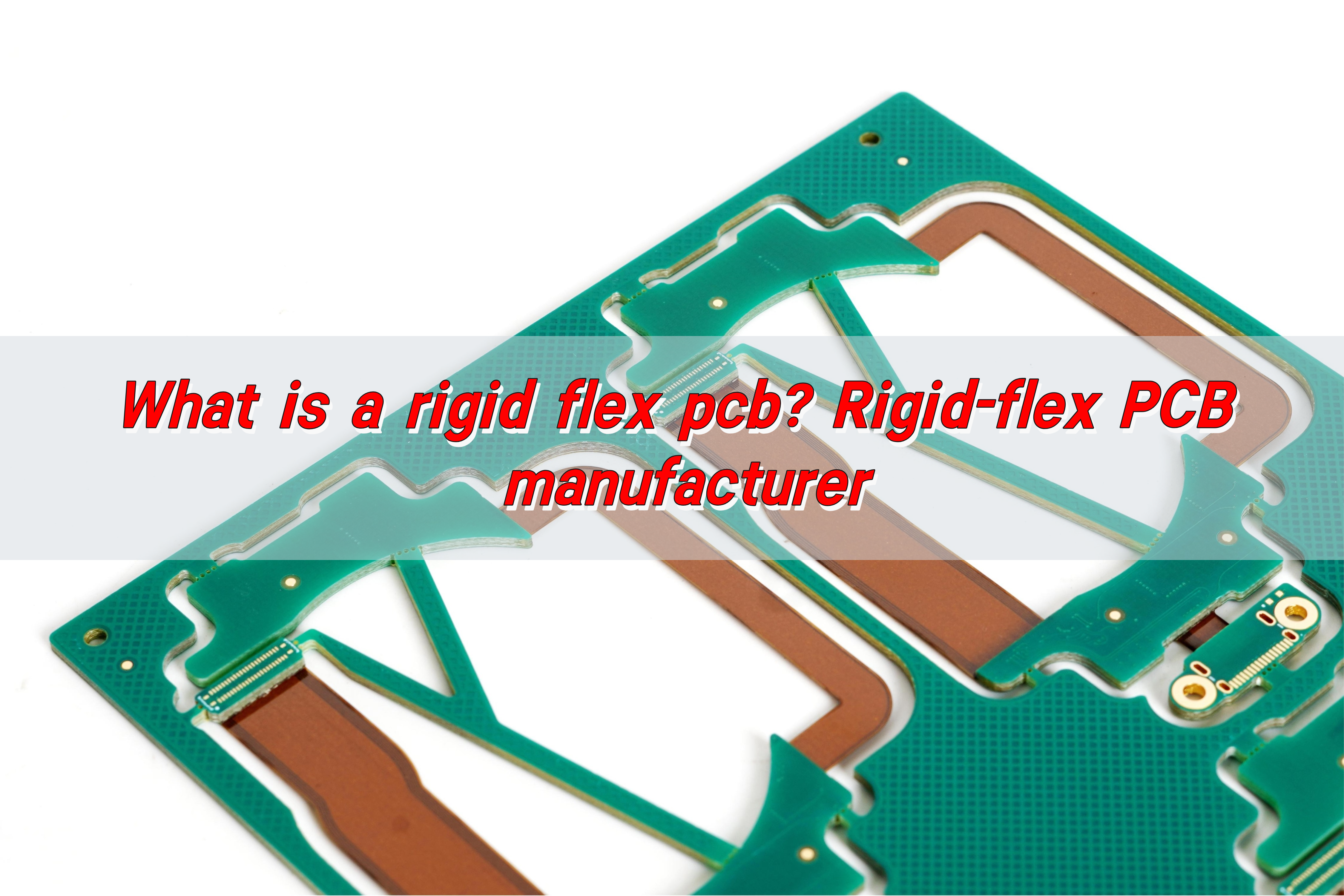
Why is rigid flex PCB for medical devices rapidly becoming the go-to option for designing miniaturized medical equipment, and how can its design, material selection, and assembly be mastered to avoid common pitfalls? This article breaks down every critical aspect of rigid flex PCB for medical devices, from its core benefits to practical design tips, certification requirements, and assembly best practices all tailored to help navigate the complexities of integrating this technology into life saving medical equipment.

Rigid Flex PCB for Medical Devices, https://www.bestpcbs.com/blog/2026/04/rigid-flex-pcb-for-medical-devices/

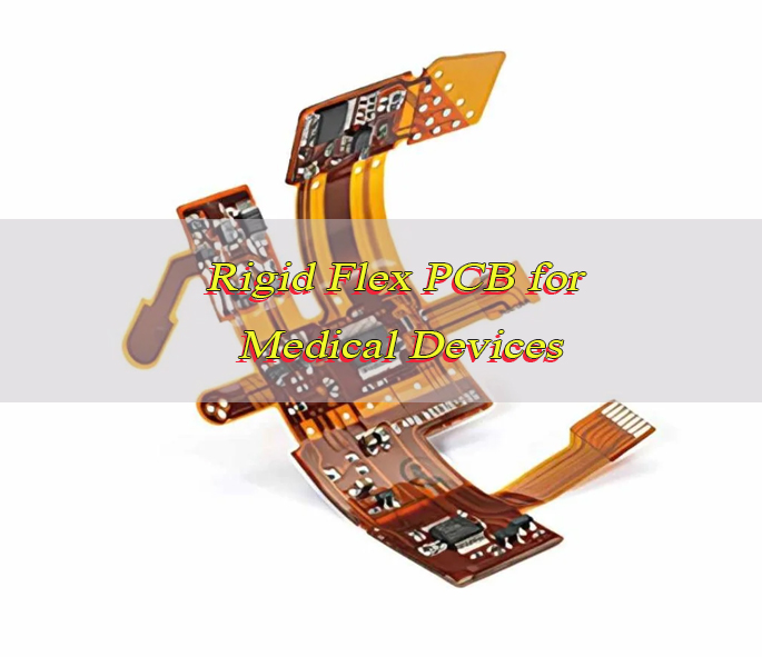
Why is Rigid Flex PCB Becoming the First Choice for Miniaturized Medical Equipment?

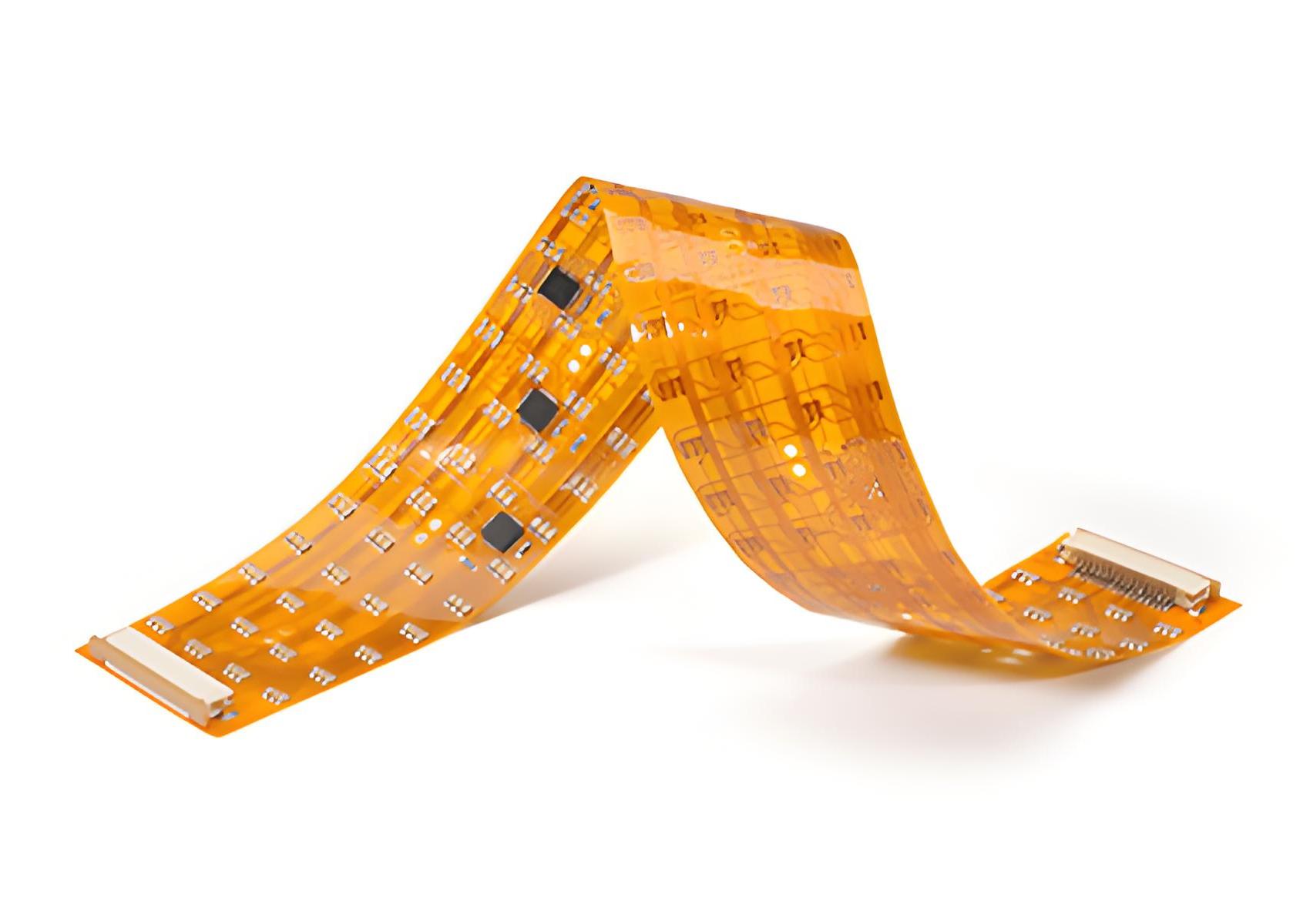
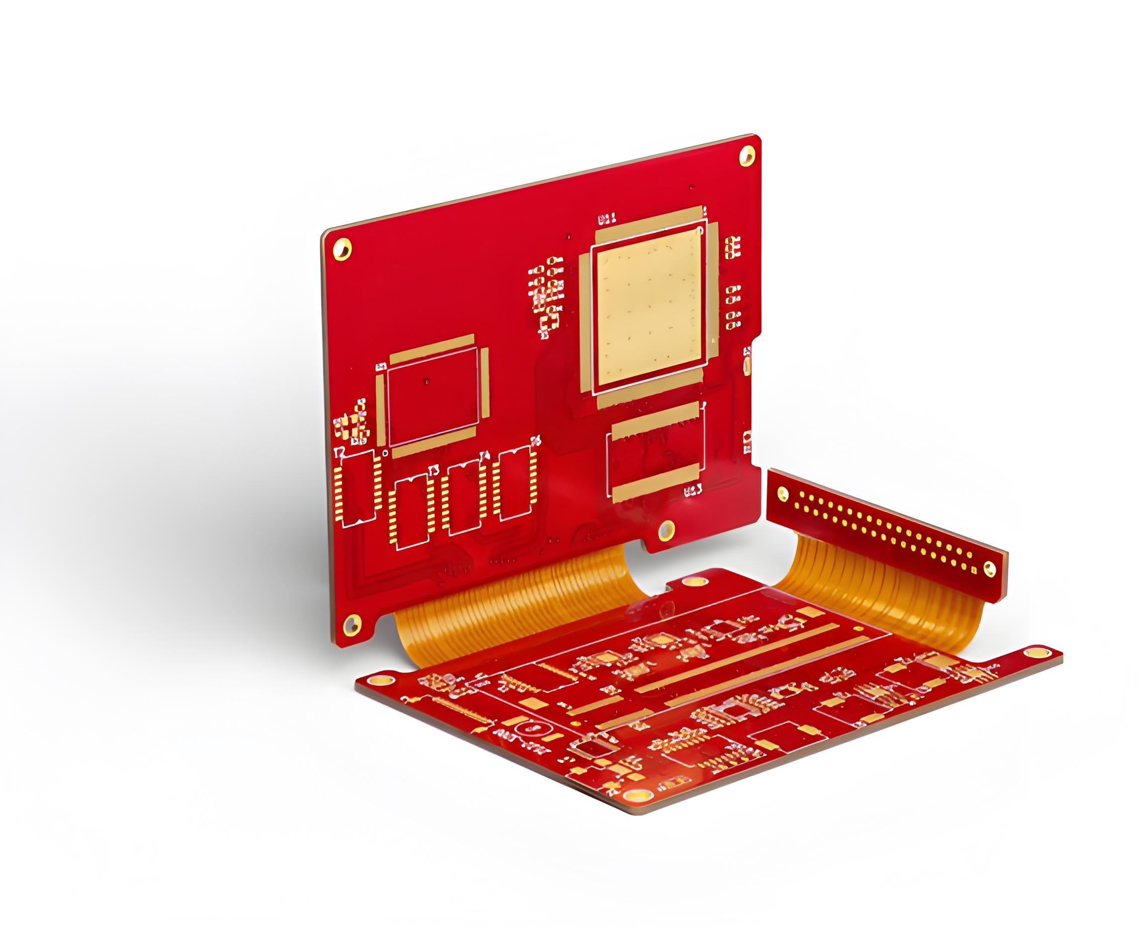
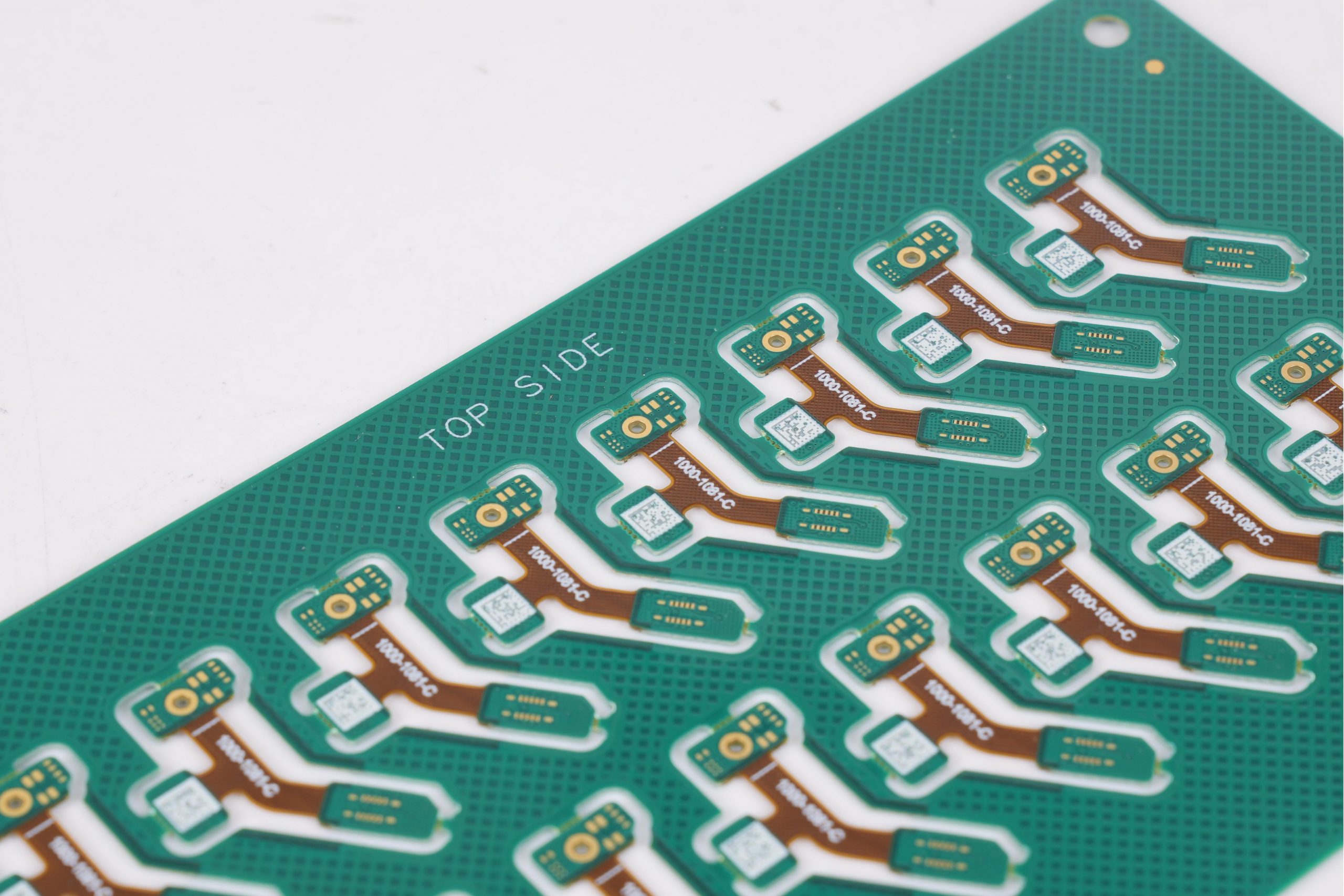
Rigid flex PCB for medical devices has emerged as the top choice for miniaturized medical equipment because it solves three core pain points faced with traditional PCBs: space constraints, weight reduction, and reliability in harsh medical environments.

Miniaturized medical devices such as portable monitors, wearable health trackers, and minimally invasive surgical tools require components to fit into extremely tight spaces while maintaining structural integrity and signal stability.

Rigid flex PCB for medical devices eliminates the need for bulky connectors and wiring harnesses that add weight and bulk, allowing for sleeker, more compact designs without sacrificing performance.

Additionally, its ability to bend and conform to the shape of medical devices reduces stress on solder joints and connections, lowering the risk of failure in devices that are frequently moved or inserted into the human body. For miniaturized equipment where every millimeter and gram matters, rigid flex PCB for medical devices delivers the versatility and durability that traditional PCBs simply cannot match.

What are the Advantages of Rigid Flex PCB for Medical Devices Compared with Traditional Rigid PCBs?

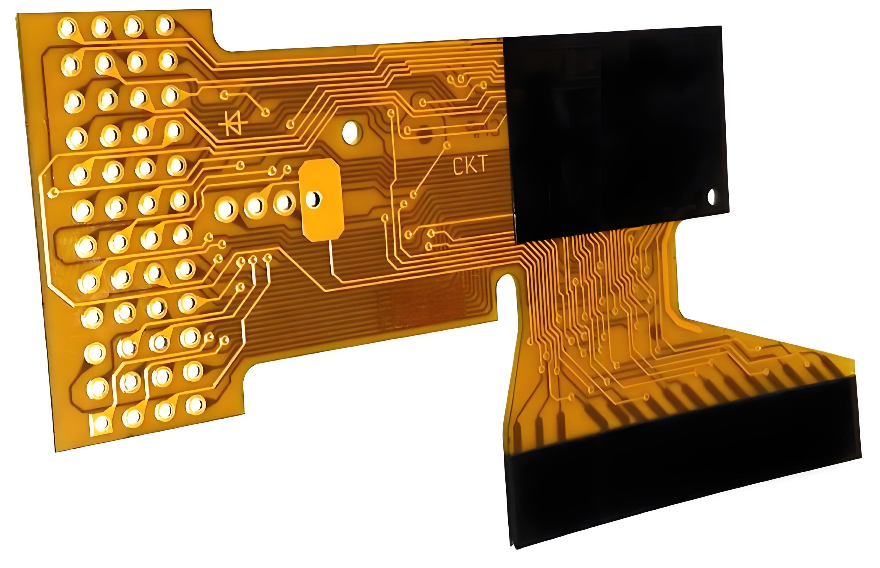
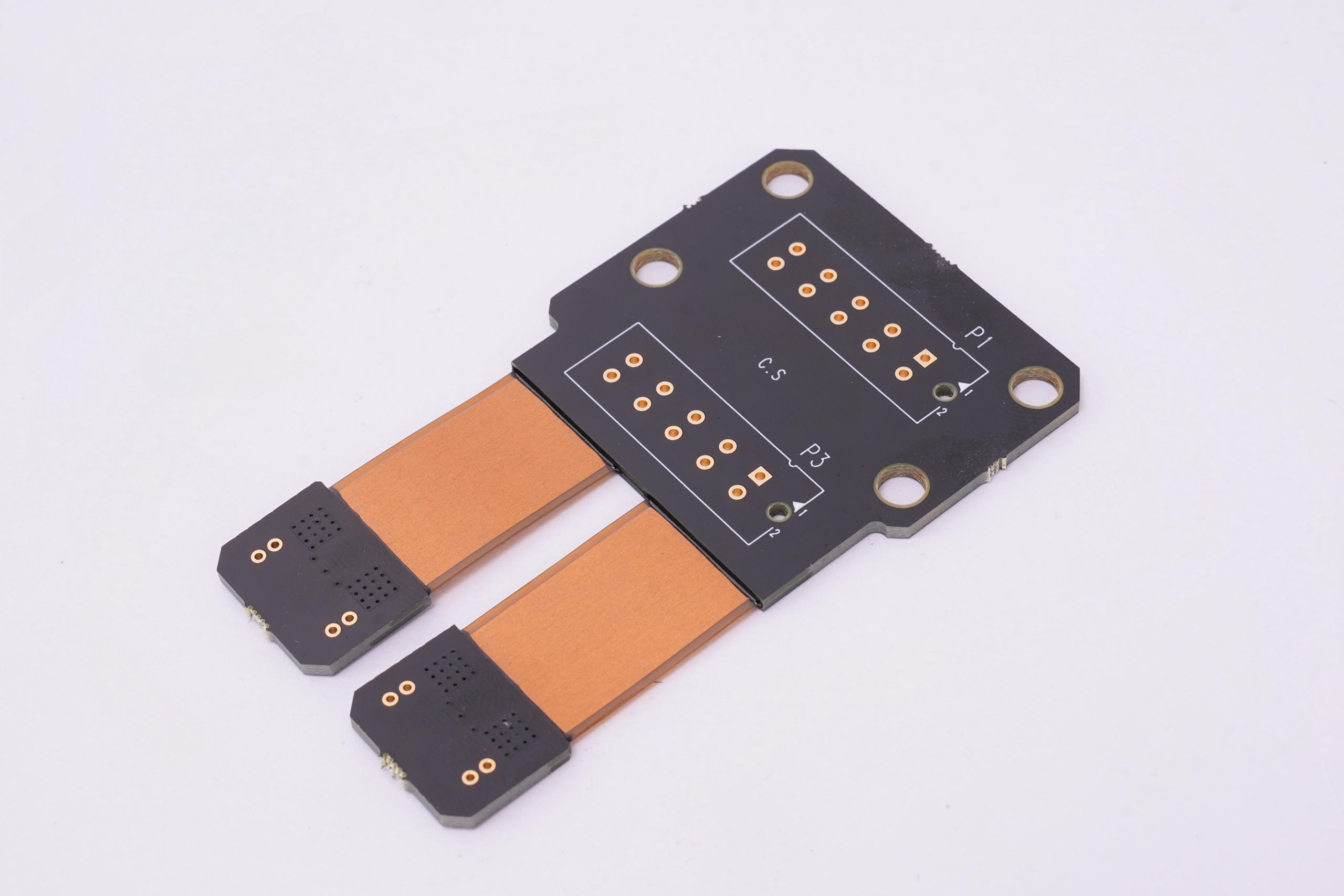
The advantages of rigid flex PCB for medical devices over traditional rigid PCBs are clear and impactful, especially in the medical industry where precision and reliability are non negotiable. Below is a detailed comparison to help understand exactly how rigid flex PCB for medical devices outperforms traditional rigid PCBs in critical areas.

Comparison CategoryRigid Flex PCB for Medical DevicesTraditional Rigid PCBs
Space EfficiencyEliminates connectors and wiring, fitting into tight spaces in miniaturized devices; can bend to conform to device shapes, reducing overall footprint by 30 50%.Requires additional connectors and wiring to connect multiple rigid boards, increasing overall size and limiting design flexibility in compact devices.
WeightLighter by 20 40% compared to rigid PCBs with wiring harnesses, critical for portable and wearable medical devices.Heavier due to extra connectors and wiring, making them less ideal for lightweight medical equipment.
ReliabilityFewer solder joints and connections reduce the risk of failure; flexible sections absorb vibration and movement, preventing stress on critical components.Multiple connectors create weak points; rigid structure cannot absorb vibration, leading to higher risk of solder joint failure in moving devices.
Design FlexibilityCan be designed to bend around components, fit into irregular shapes, and integrate multiple rigid sections into a single board, simplifying device assembly.Limited to flat, rigid shapes; requires multiple boards connected by wiring, increasing assembly complexity.
Signal IntegrityShorter signal paths reduce interference and crosstalk, critical for medical diagnostic equipment that relies on precise signal transmission.Longer signal paths through connectors increase interference, potentially compromising data accuracy in sensitive medical devices.

Which Medical Devices are Most Suitable for Using Rigid Flex PCB?

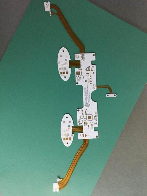
Rigid flex PCB for medical devices is ideal for any medical equipment that requires miniaturization, reliability, and flexibility especially devices that operate in harsh or constrained environments. The most suitable devices fall into four key categories, each benefiting from the unique properties of rigid flex PCB for medical devices:

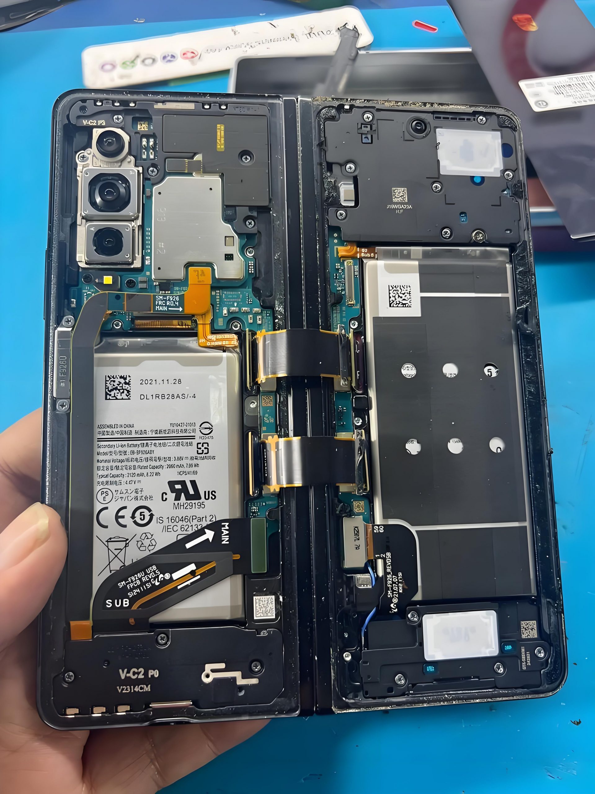
  • Portable Medical Monitors: Devices like handheld ECG monitors, blood glucose meters, and portable ultrasound machines rely on rigid flex PCB for medical devices to reduce size and weight while maintaining signal accuracy. The flexible sections allow the board to fit into slim, ergonomic designs that are easy for healthcare providers to carry.
  • Wearable Health Devices: Fitness trackers, continuous glucose monitors, and wearable heart rate monitors use rigid flex PCB for medical devices to conform to the body’s shape without sacrificing performance. The lightweight design ensures comfort for long term wear, while the durable flexible sections withstand daily movement.
  • Minimally Invasive Surgical Tools: Endoscopes, laparoscopes, and robotic surgical instruments use rigid flex PCB for medical devices to fit into narrow, curved shafts. The flexible sections allow the board to bend with the tool, while rigid sections house critical components like sensors and processors.
  • Diagnostic Equipment: MRI machines, CT scanners, and blood analysis devices use rigid flex PCB for medical devices to optimize signal integrity and reduce interference. The compact design also helps minimize the overall size of these large machines, saving space in healthcare facilities.

How to Select Materials for Rigid Flex PCB for Medical Devices to Meet Biocompatibility Requirements?

Selecting materials for rigid flex PCB for medical devices requires prioritizing biocompatibility, as these boards often come into contact with human skin, bodily fluids, or even implanted into the body. The goal is to choose materials that do not cause adverse reactions, meet industry standards, and maintain performance in medical environments. Follow these steps to select the right materials:

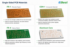
1. Prioritize Biocompatible Base Materials: For the rigid sections, use FR 4 with a biocompatible finish such as electroless nickel immersion gold or tin. For flexible sections, choose polyimide (PI) or liquid crystal polymer (LCP) both are biocompatible, resistant to bodily fluids, and offer excellent flexibility. PI works well for most applications, while LCP stands out for high frequency devices like diagnostic equipment.

2. Choose Biocompatible Adhesives: Use adhesives that meet ISO 10993 standards, such as acrylic or epoxy based adhesives. Avoid adhesives containing harmful substances like lead or cadmium, as these can leach into bodily fluids and trigger adverse reactions.

3. Select Compatible Solder Materials: Use lead free solder (e.g., SAC305) that meets RoHS and ISO 10993 requirements. Lead containing solder is strictly prohibited in medical devices, as it poses a health risk if it leaches into the body.

4. Consider Sterilization Compatibility: Materials must withstand common medical sterilization methods, including autoclaving, ethylene oxide (EtO), and gamma radiation. PI and LCP resist all three methods, while FR 4 holds up to EtO and gamma radiation but may degrade with repeated autoclaving.

Always verify material biocompatibility with test reports from certified labs, as even small variations in material composition can affect compliance. Rigid-flex pcb for medical devices, when using the right materials, meets the strictest biocompatibility standards for both external and internal use.

What Certifications Do Rigid Flex PCB Need to Comply with Medical Industry Standards?

Rigid flex PCB for medical devices must comply with global medical industry standards to ensure safety, reliability, and biocompatibility. These certifications vary by region but share core requirements for quality and performance. Below are the most critical certifications to consider:

  • ISO 13485: The primary international standard for quality management systems in the medical device industry. All manufacturers of rigid flex PCB for medical devices must hold ISO 13485 certification to demonstrate consistent ability to produce boards that meet medical requirements.
  • ISO 10993: Specifies biocompatibility requirements for materials that come into contact with the human body. Rigid flex PCB for medical devices must pass ISO 10993 tests, including cytotoxicity, sensitization, and irritation, depending on the level of contact (e.g., skin contact, internal implantation).
  • FDA 510(k) Clearance: Required for medical devices sold in the United States. While the rigid flex PCB itself does not need separate 510(k) clearance, it must be part of the device’s overall 510(k) submission, showing the board does not compromise the device’s safety or effectiveness.
  • CE Marking: Required for medical devices sold in the European Union. Rigid flex PCB for medical devices must comply with the Medical Device Regulation (MDR) 2017/745, which includes requirements for biocompatibility, quality, and performance.
  • RoHS Compliance: Mandatory in the EU, US, and many other regions. Rigid flex PCB for medical devices must be lead free and free of other restricted substances (e.g., mercury, cadmium) to meet RoHS standards.

Compliance with these certifications is non negotiable failure to meet them can result in device recalls, legal liability, and harm to patients. Always work with manufacturers who can provide certification documentation for their rigid flex PCB for medical devices.

How to Avoid Flex Fatigue Failure of Rigid Flex PCB for Medical Devices in Long-Term Use?

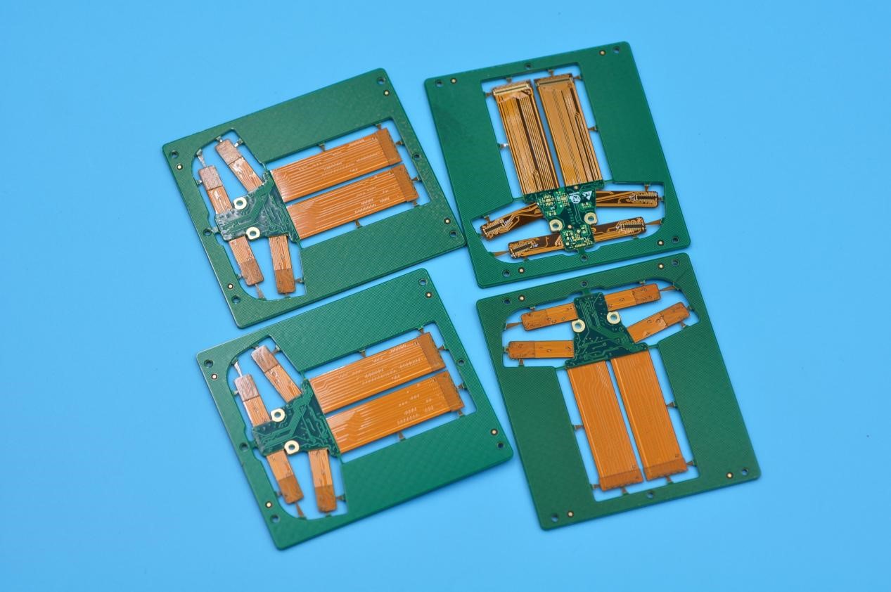
Flex fatigue failure is a common issue in rigid flex PCB for medical devices that are frequently bent or moved, such as wearable devices or surgical tools. This failure happens when the flexible sections weaken over time, leading to cracks in the copper traces or delamination. To avoid this, follow these design and manufacturing best practices:

1. Optimize Flexible Section Design: Keep the flexible sections as short as possible while still meeting design requirements. Longer flexible sections are more prone to fatigue. Use a minimum bend radius of 10 times the thickness of the flexible section for example, a 0.1mm thick flexible section should have a bend radius of at least 1mm.

2. Use Reinforcement Layers: Add reinforcement layers (e.g., polyimide or FR 4) to the flexible sections where bending occurs most frequently. This distributes stress and reduces wear on the copper traces.

3. Choose the Right Copper Thickness: Use thinner copper (1oz or less) for flexible sections, as thicker copper is more brittle and prone to cracking. Thinner copper also bends more easily without losing conductivity.

4. Avoid Sharp Bends: Design the flexible sections with smooth, gradual bends instead of sharp angles. Sharp bends concentrate stress on a small area, raising the risk of fatigue failure.

5. Test for Flex Fatigue: Conduct flex fatigue testing during the design phase to simulate long term use. Test the rigid flex PCB for medical devices by bending it repeatedly at the intended radius until failure occurs, then adjust the design to improve durability.

By following these steps, the risk of flex fatigue failure can be significantly reduced, ensuring that rigid flex PCB for medical devices remains reliable for the entire lifespan of the medical device.

Rigid Flex PCB for Medical Devices, https://www.bestpcbs.com/blog/2026/04/rigid-flex-pcb-for-medical-devices/

What Technical Capabilities should the Best Rigid Flex PCB Assembly Services for Medical Devices Have?

The best rigid flex pcb assembly services for medical devices must have specialized technical capabilities to meet the industry’s strict requirements for quality, reliability, and compliance.

Look for these capabilities when selecting an assembly partner:

  • Medical Grade Quality Control: The assembly service should have a dedicated quality control team trained in medical device standards. This includes 100% visual inspection of all boards, X ray inspection for hidden solder joints, and automated optical inspection (AOI) to detect defects.
  • Biocompatible Assembly Processes: The assembly process must use biocompatible materials and avoid contaminants. This includes lead free soldering, cleanroom assembly (Class 1000 or higher) for devices that come into contact with bodily fluids, and strict process controls to prevent contamination.
  • Expertise in Flexible Assembly: The team should have experience assembling rigid flex PCB for medical devices, including handling flexible sections without damaging them. This includes specialized equipment for bending and forming flexible sections to the required shape.
  • Compliance Documentation: The assembly service should be able to provide detailed documentation, including material certificates, test reports, and traceability records. This is critical for complying with ISO 13485 and FDA requirements.
  • Prototype and Low Volume Production Capabilities: Medical device development often requires small prototype runs followed by low volume production. The assembly service should handle both, with quick turnaround times to support rapid prototyping and product launch.

How to Ensure the Signal Integrity of Rigid Flex PCB for Medical Diagnostic Equipment?

Signal integrity is critical for medical diagnostic equipment, as inaccurate signal transmission can lead to misdiagnosis and patient harm. Rigid flex PCB for medical devices, when designed correctly, maintains excellent signal integrity even in high frequency applications. Follow these steps to ensure signal integrity:

1. Minimize Signal Path Length: Design the rigid flex PCB for medical devices with the shortest possible signal paths. Longer paths increase capacitance and inductance, leading to signal degradation. Use the flexible sections to route signals directly between components, avoiding unnecessary detours.

2. Impedance Matching: Match the impedance of the PCB traces to the components (e.g., sensors, processors) to reduce signal reflection. Use impedance calculators to determine the correct trace width and spacing, especially for high frequency signals (above 1 GHz).

3. Separate Analog and Digital Traces: Route analog and digital traces on separate layers or keep them at least 3mm apart to avoid crosstalk. Analog signals are sensitive to interference from digital signals, which can compromise diagnostic accuracy.

4. Use Ground Planes: Incorporate a solid ground plane in the rigid flex PCB for medical devices to reduce noise and improve signal integrity. The ground plane acts as a shield, absorbing interference and providing a stable reference voltage.

5. Test Signal Integrity: Use tools like time domain reflectometry (TDR) and signal integrity analyzers to test the board during design and production. This helps identify issues like signal reflection, crosstalk, and attenuation before the board is integrated into the device.

Is Rigid Flex PCB for Medical Devices Suitable for Implantable Medical Devices?

Yes, rigid flex pcb for medical devices is suitable for implantable medical devices, provided it meets strict biocompatibility, durability, and reliability requirements. Implantable devices such as pacemakers, defibrillators, and neurostimulators require boards that are small, lightweight, and able to withstand the harsh environment inside the human body.

Rigid flex PCB for medical devices meets these requirements by eliminating bulky connectors, reducing size and weight, and using biocompatible materials that do not cause adverse reactions. The flexible sections allow the board to conform to the shape of the implant, while rigid sections house critical components like batteries and processors.

However, implantable rigid flex PCB for medical devices must undergo additional testing, including long term biocompatibility tests (ISO 10993 1) and sterilization validation, to ensure they are safe for permanent implantation. Working with a manufacturer experienced in implantable devices is critical to ensuring compliance and reliability.

Rigid Flex PCB for Medical Devices, https://www.bestpcbs.com/blog/2026/04/rigid-flex-pcb-for-medical-devices/

What Quality Testing Items are Essential for Rigid Flex PCB for Medical Devices?

Quality testing is critical for rigid flex pcb for medical devices, as even minor defects can compromise device performance and patient safety.

Below are the essential testing items that every rigid flex PCB for medical devices should undergo before integration into a medical device:

  • Visual Inspection: A thorough visual inspection to check for surface defects, such as scratches, delamination, and solder bridges. This can be done manually or with automated optical inspection (AOI) for greater accuracy.
  • X Ray Inspection: Used to inspect hidden solder joints and internal layers, ensuring there are no voids, cracks, or misalignments that could lead to failure.
  • Flex Fatigue Testing: Simulates long term use by bending the flexible sections repeatedly at the intended radius, ensuring the board does not crack or delaminate.
  • Biocompatibility Testing: Tests for cytotoxicity, sensitization, and irritation (per ISO 10993) to ensure the board is safe for contact with the human body.
  • Signal Integrity Testing: Uses TDR and signal analyzers to verify that signals are transmitted accurately without interference or degradation.
  • Sterilization Validation: Tests the board’s ability to withstand medical sterilization methods (autoclaving, EtO, gamma radiation) without losing performance.
  • Electrical Testing: Includes continuity testing, insulation resistance testing, and voltage testing to ensure the board functions correctly under operating conditions.

How to Choose Best Rigid Flex PCB Assembly Services for Medical Devices?

Choosing the right rigid flex pcb assembly services for medical devices is critical to ensuring a device meets quality, compliance, and performance requirements. Follow this step by step process to select the best partner:

1. Verify Compliance: Ensure the assembly service is ISO 13485 certified and has experience with medical device regulations (FDA, MDR). Ask for documentation of their compliance processes and past medical device projects.

2. Evaluate Technical Expertise: Look for a service with specialized experience in rigid flex PCB assembly for medical devices. Ask about their experience with biocompatible materials, flex fatigue prevention, and signal integrity optimization.

3. Review Quality Control Processes: Inquire about their quality control measures, including inspection methods (AOI, X ray), test procedures, and defect rates. A reliable service will have a defect rate of less than 0.1% for medical grade boards.

4. Check Traceability: Ensure the service provides full traceability for all materials and components, including lot numbers, material certificates, and test reports. This is critical for compliance and recall management.

5. Assess Communication and Turnaround: Choose a service that communicates clearly and provides regular updates on a project. Medical device development often has tight deadlines, so look for a partner with quick turnaround times for prototypes and production runs.

6. Request Samples and References: Ask for samples of their past rigid flex PCB for medical devices to evaluate quality. Also, request references from other medical device professionals who have worked with the service.

What are the Future Development Trends of Rigid Flex PCB for Medical Devices?

The future of rigid flex PCB for medical devices is driven by advancements in medical technology, miniaturization, and patient centered care. Staying ahead of these trends helps design more innovative and effective medical devices. Below are the trends to watch:

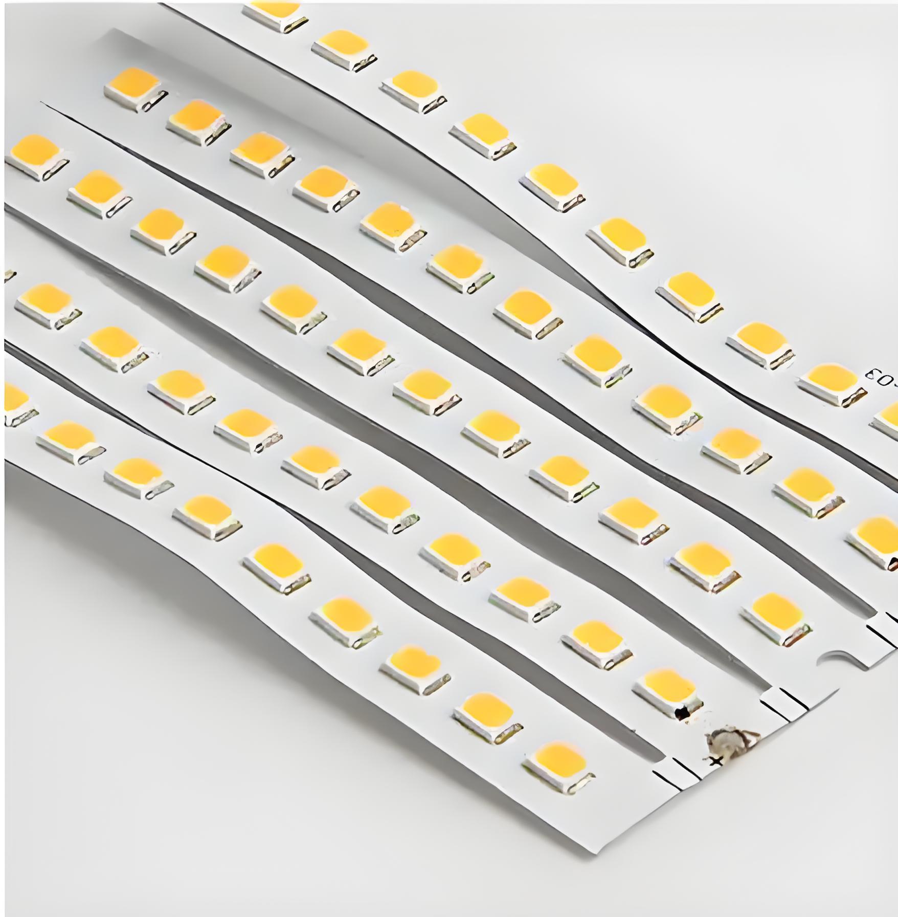
  • Integration with Flexible Electronics: Rigid flex PCB for medical devices will increasingly integrate with flexible sensors and displays, enabling more advanced wearable and implantable devices. This includes flexible OLED displays and biosensors that can monitor vital signs in real time.
  • Miniaturization and High Density Interconnects: As medical devices become smaller, rigid flex PCB for medical devices will use smaller components and higher density interconnects (HDIs) to fit more functionality into a smaller space. This includes microvias and fine pitch components.
  • Improved Biocompatible Materials: New biocompatible materials, such as bioresorbable polymers, will be used in rigid flex PCB for medical devices, allowing for implantable devices that dissolve naturally in the body after use. This eliminates the need for surgical removal.
  • Smart Manufacturing and Automation: Assembly of rigid flex PCB for medical devices will become more automated, using AI and machine learning to improve quality and reduce defects. This includes automated assembly, inspection, and testing processes.
  • Enhanced Signal Integrity for 5G and IoT: With the rise of 5G and IoT in medical devices, rigid flex PCB for medical devices will be designed to support higher frequencies and faster data transmission, enabling real time remote monitoring and diagnostics.
Rigid Flex PCB for Medical Devices, https://www.bestpcbs.com/blog/2026/04/rigid-flex-pcb-for-medical-devices/

FAQs About Rigid-Flex PCB for Medical Devices

Q1: Can rigid flex PCB for medical devices be used in high temperature medical environments?

A1: Yes, rigid flex PCB for medical devices can be used in high temperature environments, provided the right materials are selected. Polyimide (PI) flexible sections and FR 4 rigid sections can withstand temperatures up to 260°C, making them suitable for devices used in autoclaving or high temperature diagnostic equipment. For extreme temperatures (above 300°C), liquid crystal polymer (LCP) is recommended, as it offers better thermal stability.

Q2: How long does a rigid flex PCB for medical devices typically last in implantable applications?

A2: A well designed and manufactured rigid flex PCB for medical devices can last 10-15 years in implantable applications. This depends on the materials used, the design (especially flex fatigue prevention), and the environment inside the body. Implantable rigid flex PCB for medical devices undergo rigorous testing to ensure they can withstand long term exposure to bodily fluids and temperature fluctuations.

Q3: Is rigid flex PCB for medical devices more expensive than traditional rigid PCBs?

A3: Yes, rigid flex PCB for medical devices is typically 20-50% more expensive than traditional rigid PCBs due to the specialized materials and assembly processes required. However, the cost is offset by reduced component count (fewer connectors and wiring), smaller device size, and higher reliability. For medical devices where safety and performance are critical, the investment in rigid flex PCB for medical devices is often worth it.

Q4: Can rigid flex PCB for medical devices be repaired if it fails?

A4: In most cases, rigid flex PCB for medical devices cannot be repaired, especially if it is part of an implantable or critical diagnostic device. The flexible sections are prone to permanent damage if bent beyond their design limits, and repairing solder joints on flexible sections is difficult without compromising reliability. For this reason, it is critical to design and test rigid flex PCB for medical devices thoroughly to avoid failure.

Q5: What is the difference between rigid flex PCB for medical devices and rigid-flex pcb for medical devices?

A5: There is no functional difference between rigid flex PCB for medical devices and rigid-flex pcb for medical devices. The hyphenated variant (rigid-flex pcb for medical devices) is a common spelling used in industry searches and documentation, but both refer to the same type of board one that combines rigid and flexible sections to provide versatility and compactness for medical devices.

You may also like

Rigid Flex Circuit
Friday, April 10th, 2026

Rigid flex circuit is a PCB structure that combines rigid board sections and flexible circuit layers into one integrated unit. It offers the strength of rigid FR4 boards and the space-saving advantage of flexible circuits. Compared with a standard flex PCB with stiffeners, a true rigid flex board is built with plated through holes (PTH) that electrically connect the rigid and flexible layers inside the structure.

Rigid flex PCBs are widely used in medical devices, aerospace electronics, industrial controls, automotive systems, and advanced consumer products where stable performance and compact structure are required.

What Is a Rigid Flex Circuit?

A rigid flex circuit is a hybrid PCB made by laminating rigid substrates and flexible substrates into one board structure. The rigid sections support component mounting, while the flexible sections allow bending or folding during installation.

This design helps engineers reduce assembly size, simplify internal wiring, and improve product reliability. Instead of using multiple separate boards connected by cables or connectors, a rigid flex PCB combines these functions into one integrated interconnection platform.

Main Features of Rigid Flex PCB

  • Combines rigid and flexible substrates in one board
  • Uses plated through holes for internal electrical interconnection
  • Supports compact and three-dimensional assembly design
  • Reduces connectors, cables, and manual soldering points
  • Improves reliability in high-vibration and limited-space applications
Rigid Flex Circuit

Rigid Flex Circuit

Our Typical Project Cases

Case 1 – Medical Portable Monitoring Device Rigid Flex PCB

Application: Portable medical monitoring system

Board Type: 6 Layer Rigid Flex PCB

Material: FR4 + Polyimide

Surface Finish: ENIG

Key Requirement: Compact size, stable signal, high reliability

Medical Portable Monitoring Device Rigid Flex PCB

Case 2 – Automotive Camera Module Rigid Flex PCB

Application: Automotive camera system

Board Type: 4 Layer Rigid Flex PCB

Material: High Tg FR4 + Polyimide

Surface Finish: ENIG

Key Requirement: Vibration resistance, compact structure

Automotive Camera Module Rigid Flex PCB

Case 3 – Industrial Control System Rigid Flex PCB

Application: Industrial control module

Board Type: 8 Layer Rigid Flex PCB

Material: FR4 + Polyimide

Surface Finish: ENIG

Key Requirement: High density routing, stable interconnection

Industrial Control System Rigid Flex PCB

Case 4 – Consumer Electronics Folding Device Rigid Flex PCB

Application: Foldable consumer electronic device

Board Type: 4 Layer Rigid Flex PCB

Material: FR4 + Polyimide

Surface Finish: ENIG

Key Requirement: Repeated bending, compact layout

Consumer Electronics Folding Device Rigid Flex PCB

Rigid Flex PCB vs. Flex PCB with Stiffener

A rigid flex circuit is different from a flex PCB with FR4 or polyimide stiffeners.

In a flex PCB with stiffener, the stiffener is added only for local support. It is usually attached by adhesive and does not provide plated electrical interconnection between layers.

In a rigid flex PCB, the rigid and flexible sections are laminated into one complete structure, and the layers are electrically connected through plated through holes. This gives the board stronger structural integrity and better long-term reliability.

Key Difference

ItemRigid Flex CircuitFlex PCB with Stiffener
StructureIntegrated rigid and flex laminateFlex circuit with added support layer
Electrical InterconnectionYes, through plated holesNo plated interconnection through stiffener
Mechanical StabilityHigherModerate
Assembly IntegrationBetterLimited
Typical UseHigh-reliability compact productsLocal reinforcement only

Our Rigid Flex PCB Manufacturing Capabilities

Below is a typical reference table for custom rigid flex PCB manufacturing capability.

ParameterTypical Capability
Rigid Flex StructureSingle-sided, double-sided, multilayer rigid flex
Base MaterialsFR4 + Polyimide
Layer Count2L to 50L
Rigid Layer MaterialStandard FR4 / High Tg FR4
Flexible Layer MaterialPolyimide (PI)
Copper Thickness0.5 oz to 4 oz
Board ThicknessCustom build-up
Flex ThicknessBased on stack-up design
Min Line / Space4/4 mil
Min Drill Hole0.2 mm
Surface FinishENIG, HASL, OSP, Immersion Tin, Immersion Silver
Solder MaskGreen, Black, White, Red, Blue, Yellow
CoverlayYellow / Black / White
Stiffener OptionFR4, PI, Stainless Steel
Impedance ControlSupported
Via TypePTH, blind via, buried via, microvia based on design
Assembly ServicePCB fabrication + SMT assembly
Production TypePrototype to mass production
Assembly SupportSMT, THT, mixed technology assembly
File SupportGerber, drill file, stack-up, assembly drawing, BOM

Common Rigid Flex Stack-Ups

Rigid flex PCB structures are usually designed as multilayer constructions. The final stack-up depends on routing density, bend radius, thickness target, and mechanical design requirements.

4 Layer Rigid Flex

Option 1

  • 1L FR4
  • 2L FPC
  • 1L FR4

Option 2

  • 2L FR4
  • 2L FPC

6 Layer Rigid Flex

Option 1

  • 2L FR4
  • 2L FPC
  • 2L FR4

Option 2

  • 1L FR4
  • 4L FPC
  • 1L FR4

8 Layer Rigid Flex

Option 1

  • 2L FR4
  • 4L FPC
  • 2L FR4

Option 2

  • 1L FR4
  • 6L FPC
  • 1L FR4

Option 3

  • 2L FPC
  • 4L FR4
  • 2L FPC

Option 4

  • 1L FPC
  • 6L FR4
  • 1L FPC

Special Rigid Flex Structures for Custom Applications

Besides standard multilayer designs, some projects require custom rigid flex configurations for special packaging or functional needs.

2 Layer Rigid Flex

  • 1L FR4
  • 1L FPC

3 Layer Rigid Flex

Option 1

  • 1L FR4
  • 1L FPC
  • 1L FR4

Option 2

  • 1L FPC
  • 1L FR4
  • 1L FPC

These special designs are often used in compact electronic modules where a simple but integrated board structure is needed.

Design and Manufacturing Considerations

A reliable rigid flex PCB depends not only on layout, but also on manufacturability planning. Early engineering review can help avoid cracking, delamination, poor bend performance, and assembly issues.

Key Points to Consider

  • Stack-up design between rigid and flex areas
  • Bend radius and bending direction
  • Copper balancing in flex zones
  • Coverlay opening design
  • Stiffener placement
  • Hole location near bend areas
  • Final thickness control
  • Component placement on rigid sections only
  • Impedance and signal path planning for high-speed designs

A good rigid flex supplier should review these details before production, not after problems appear.

Typical Applications of Rigid Flex PCB

  • Medical monitoring and portable diagnostic devices
  • Aerospace and defense electronics
  • Industrial control systems
  • Automotive electronic modules
  • Cameras and optical devices
  • Consumer electronics with compact internal layouts

Why Work With EBest Circuit (Best Technology) for Rigid Flex PCB?

EBest Circuit provides custom rigid flex PCB manufacturing for projects that require compact structure, stable interconnection, and reliable quality. With over 20 years of PCB experience, we support customers from design review to fabrication and assembly.

What We Offer

  • Custom rigid flex PCB fabrication
  • Stack-up review and DFM support
  • PCB and PCBA one-stop service
  • Prototype and volume production support
  • Material and process suggestion based on application
  • Fast response for RFQ and engineering questions

Our engineering team understands the practical challenges behind rigid flex structures and helps customers improve both design feasibility and production stability.

What Files Are Recommended for RFQ?

To speed up quotation and technical review, it is helpful to provide:

  • Gerber files
  • Drill files
  • Stack-up information
  • Fabrication drawing
  • Assembly drawing
  • BOM list
  • Pick and place file if assembly is needed

Clear documentation helps reduce back-and-forth communication and improves quote accuracy.

FAQs

1. What is the minimum bend radius for rigid flex PCB?

The bend radius depends on the flex thickness and copper structure. A common guideline is:

  • Single-layer flex: 6–10 Ɨ thickness
  • Double-layer flex: 10–15 Ɨ thickness
  • Multilayer flex: 15–20 Ɨ thickness

Proper bend radius design is critical to prevent copper cracking or delamination during use.

2. Can components be placed on the flexible area?

In most cases, components should be mounted only on the rigid sections.

Placing components on flex areas is possible in special designs, but it requires careful reinforcement, controlled bending conditions, and additional manufacturing considerations. For standard designs, keeping components on rigid areas improves reliability and assembly stability.

3. What materials are used in rigid flex PCB?

Rigid flex circuits typically use:

  • Rigid layers: FR4 or high Tg FR4
  • Flexible layers: Polyimide (PI)
  • Coverlay: Polyimide film with adhesive
  • Stiffeners: FR4, PI, or stainless steel

Material selection depends on temperature requirements, bending cycles, and electrical performance.

4. How many bending cycles can a rigid flex PCB withstand?

The bending life depends on the design and materials. With proper design, rigid flex circuits can withstand thousands to millions of bending cycles.

Key factors include:

  • Copper thickness
  • Flex layer structure
  • Bend radius
  • Material quality

Engineering optimization is important for applications requiring repeated movement.

Get a Quote for Your Rigid Flex Circuit Project

Looking for a reliable rigid flex PCB manufacturer for your next project? Best Technology can support your design with engineering review, custom stack-up guidance, and stable production service.

Send your Gerber files, stack-up details, or project requirements to sales@bestpcbs.com for quotation and technical support.

You may also like

2oz Thicker Copper Rigid-Flex PCB Manufacturing & Challenges
Wednesday, December 31st, 2025

Recently, Best Technology faced a huge challenge in a 2oz copper rigid flex PCB manufacturing, this board appeared simple on the drawing but revealed multiple layers of engineering challenges once entering mass production. But finally, we finished this project very well and overcome this challenge, let’s see what are the challenges on this project and how does our team overcome them!

Project Introduction

The board used a 70/25 double-sided adhesive ED flexible substrate with PI25/AD50 coverlay, coupled with a 2+2 layers dual access structure that required thick copper, small annular rings, narrow spacings, and FR4 stiffeners with extremely limited clearance. Each of these parameters independently creates difficulty, but combined, they demand precise collaboration between engineering, fabrication, and process control.

This article explains:

  • Why the design was inherently difficult
  • What manufacturing risks were present
  • How our engineering team solved each challenge
  • What PCB designers should avoid in similar projects
  • Why Best Technology can manufacture such high-reliability rigid-flex PCBs

Material Structure and Key Design Parameters

The board consisted of the following:

  • Flexible substrate: 70/25 double-sided adhesive ED copper
  • Coverlay: PI 25 µm + Adhesive 50 µm
  • Base copper: 2 oz copper
  • Layer count: Four-layer rigid-flex structure
  • Critical routing: 0.15 mm minimum trace/space
  • Plated hole: 0.66 mm with hole spacing of only 0.60 mm
  • Annular ring: 0.05 mm on certain pads
  • Stiffener: FR4 stiffener with 0.95 mm stiffener hole and 0.31 mm ribs
Material Structure and Key Design Parameters

This combination is common in advanced HDI rigid-flex PCB manufacturing, yet its manufacturability depends heavily on copper behavior, adhesive flow, and drilling tolerances.

Why This Rigid-Flex PCB Was Inherently Difficult?

1. Thick copper increases side-etching risk

    With 2 oz copper, the etching rate is higher and lateral etch—often called side-etch—is harder to control. In this case, the side-etching amount reached: 0.0070 ± 0.003 mm. For ultra-fine traces in a rigid-flex PCB design, this will eat into the design margin.

    2. Small annular rings compromise via reliability

    Pads with 0.05 mm annular ring severely restrict drilling tolerance. In flex-rigid PCB fabrication, annular rings below 0.10 mm are classified as high-risk features.

    Why This Rigid-Flex PCB Was Inherently Difficult?

    3. Extremely tight stiffener clearance

    The stiffener needed:

    • ±0.20 mm placement tolerance
    • ±0.05 mm drilling tolerance

    But the designer only left 0.15 mm clearance, causing a mismatch between rigid-flex PCB stiffener alignment tolerance and actual manufacturing capability.

    4. Thin FR4 stiffener ribs cause glue overflow

    Ribs only 0.31 mm wide cannot allow adhesive to retreat during bonding, causing pure glue to overflow and block the stiffener holes.

    Why This Rigid-Flex PCB Was Inherently Difficult?

    Technical Challenge #1: Thick Copper Etching with Narrow Spacing

    A 2 oz thick copper PCB combined with:

    • 0.15 mm trace/space
    • 0.05 mm annular ring
    • 0.66 mm PTH

    creates a situation where compensation is unavoidable.

    However, after compensation (~0.007 mm), the remaining trace width would drop to:

    0.08 mm (0.15 – 0.07 mm)

    This is below the safe manufacturability range of most rigid-flex PCB suppliers.

    Best Technology’s solution

    • Eliminated compensation on 0.15 mm traces
    • Implemented fine-tuned etching control
    • Maintained ~0.10 mm final copper width
    • Ensured full electrical reliability

    This is a proven strategy in advanced rigid-flex PCB manufacturing for thick-copper builds.

    Technical Challenge #2: Annular Ring Integrity in Plated Through Holes

    Annular rings <0.10 mm are extremely vulnerable to:

    • Drill wander
    • Etching undershoot
    • Copper thinning

    This is especially critical in high-reliability rigid-flex PCBs, where via integrity is essential.

    Best Technology’s solution

    • Applied rigid-board-level PTH plating process
    • Improved copper thickness inside the via barrel
    • Adjusted drilling control to 0.65 ± 0.075 mm
    • Customer accepted partial ring breakage as long as electrical integrity remained intact

    This ensured consistent via performance even in ultra-dense rigid-flex PCB layouts.

    rigid flex pcb

    Technical Challenge #3: Stiffener Bonding, Alignment, and Adhesive Overflow

    1. Why stiffener tolerance was problematic

    In rigid-flex PCB assembly, stiffeners are critical for mechanical reinforcement. However:

    • Hole spacing was only 0.60 mm
    • Stiffener clearance only 0.15 mm per side
    • Combined tolerance ±0.25 mm

    This inevitably leads to the stiffener covering the pads unless advanced alignment controls are used.

    rigid flex pcb with stiffener

    2. Why glue overflow occurs

    Thin ribs (0.31 mm) cannot provide an escape path for adhesive. During lamination:

    • The glue squeezes into the holes
    • Holes become blocked
    • Boards fail inspection

    3. Best Technology’s engineered solution

    • Pre-laminated pure adhesive onto FR4 stiffener
    • Re-drilled stiffener holes after bonding
    • Greatly reduced glue overflow
    • Added 100% AOI + manual inspection for hole clearing
    • Rejected defective boards, shipped only fully passing units

    This is a common best practice in flex PCB stiffener processing when tolerances are tight.

    DFM Guidelines for Rigid-Flex PCB Designers

    1. Avoid annular rings under 0.15 mm, especially in 2 oz copper flex-rigid PCB design.
    2. Avoid combining thick copper with fine lines, this will increase manufacturing risk.
    3. Ensure stiffener clearance > total tolerance stack-up. If your clearance is smaller than the alignment tolerance, the stiffener will inevitably shift.
    4. Keep stiffener ribs ≄0.5 mm
    5. Send your design for DFM review before finalizing. A good rigid-flex PCB manufacturer will help adjust the stack-up, drill size, and stiffener layout to avoid expensive redesigns.

    This case demonstrates how a complex rigid-flex PCB—with 2 oz copper, ultra-fine traces, small annular rings, and extreme stiffener constraints—can be successfully manufactured through detailed engineering, advanced process control, and disciplined quality screening.

    Best Technology combines strong fabrication capability with practical DFM insight, enabling customers to produce compact, reliable, and manufacturable rigid-flex PCB designs that perform consistently under demanding conditions.

    If you need support with your next rigid-flex or flex PCB project, our engineering team is ready to assist with stack-up review, DFM checks, or trial builds.

    You may also like

    What is Rigid-Flex Copper Substrate? Rigid Flex PCB
    Thursday, August 14th, 2025

    Rigid-flex copper substrate combines the best of both rigid PCBs and flexible circuits into a single circuit board. This design is both practical and innovative. Its applications range from advanced medical devices to aerospace systems. Its versatility stems from the way its copper layer is integrated with both flexible and rigid components, enabling smooth folding without disrupting connections.

    What is Rigid-Flex Copper Substrate? Rigid Flex PCB

    Do you want to know:

    • What are its advantages over ordinary substrates?
    • How many frequent bends can it withstand?
    • How is heat dissipation guaranteed?
    • Does it support complex circuits and unusual shapes?
    • What is the prototype production cycle?
    • What are the quality standards?

    BEST Technology, a professional metal-based circuit board manufacturer, can answer your questions:

    • The high heat dissipation of a rigid substrate combined with the flexibility of a flexible substrate allows for complex applications.
    • Dynamic bending resistance of ≄100,000 times (R=1mm) ensures continuous circuitry and stable performance.
    • Highly conductive adhesive layer combined with a full copper surface design results in a thermal resistance of ≤0.8°C/W, improving heat dissipation by 30%+ in high-temperature environments.
    • Minimum line width/spacing of 3 mils, supports unusual shapes and stepped structures, and an accuracy error of ≤±0.1 mil.
    • Prototypes take 3 days, and mass production takes 7-15 days. Compliant with IPC-A-600H, with over 20 tests and 24-hour customer service.

    What is rigid-flex copper substrate?

    Rigid-flex copper substrate is a hybrid printed circuit board that has rigid and flexible layers combined into one structure. The rigid parts provide mechanical stability, while the flexible layers connect them, allowing bending or folding during assembly or use.

    This combination removes the need for connectors or separate ribbon cables, reducing the risk of signal loss or failure. In many designs, rigid-flex boards improve reliability and performance at the same time.

    The rigid flex PCB design typically uses copper foil as the conductor. Copper is preferred because it offers excellent conductivity, mechanical strength, and resistance to fatigue. The result is a board that can bend without losing electrical integrity.

    Rigid-flex copper substrate with different layers

    Layer count in a rigid-flex board greatly impacts performance, cost, and applications.

    • 1. 2-layer rigid-flex copper substrate

    This is the simplest form. It offers enough flexibility for basic designs and is often used in consumer devices, portable gadgets, and small control panels. It’s affordable and fast to produce.

    • 2. Dual-layer rigid-flex copper substrate

    Similar to the 2-layer version but often built with reinforced materials. It provides more strength and is ideal for designs that require slight bending during use.

    • 3. 4-layer rigid-flex copper substrate

    With more copper layers, it allows complex routing, better signal performance, and improved EMI shielding. The 4-layer copper-based rigid-flex PCB is common in automotive electronics and handheld medical devices.

    • 4. 6-layer rigid-flex copper substrate

    This high-end design is built for advanced technology. It supports multiple high-speed signals, complex interconnections, and precise impedance control. Aerospace systems, industrial control machines, and military electronics often use this type.

    What is Rigid-Flex Copper Substrate? Rigid Flex PCB

    Choosing the right layer count depends on design needs, available space, and budget. Each option balances performance and flexibility differently.

    How does rigid flex PCB work?

    The rigid flex PCB works by integrating multiple circuit layers—some rigid, some flexible—into one laminated structure. During manufacturing, the flexible layers are bonded with polyimide material, while the rigid parts are reinforced with FR4 or other stiffeners.

    When installed, the flexible sections bend to fit inside tight enclosures. This makes it perfect for 3D assembly. The electrical signals flow through copper traces that remain continuous across the rigid and flexible areas, eliminating the need for connectors.

    By reducing interconnections, rigid flex PCBs lower the risk of mechanical failure, improve signal speed, and make products more reliable in harsh conditions.

    Why choose rigid-flex copper substrate?

    There are many reasons to choose a rigid-flex copper substrate.

    • Space efficiency: This design allows components to be placed closer together, reducing product size.
    • Durability: Flexible sections handle repeated bending without breaking. This is important in devices exposed to motion or vibration.
    • Improved performance: Fewer connectors mean faster signal transmission and less interference.
    • Lightweight construction: Replacing multiple boards and cables with one unit cuts down weight.
    • Design freedom: Three-dimensional design is possible, allowing for better utilization of interior space.

    From smartphones to satellites, rigid-flex boards help achieve higher performance without increasing size.

    Which flexible PCB material is best?

    The performance of a rigid-flex PCB depends heavily on the flexible material. Most use flexible circuit technologies with polyimide films, which offer excellent heat resistance, flexibility, and electrical insulation.

    Polyimide is also stable in harsh environments, making it a trusted choice for aerospace, automotive, and industrial applications. For added strength, some designs use adhesive-less laminates, which improve bending capability and reduce thickness.

    Copper foil is the heart of the conductor. Rolled annealed copper is preferred for its flexibility and fatigue resistance, while electro-deposited copper works well for more rigid applications.

    What is Rigid-Flex Copper Substrate? Rigid Flex PCB

    The choice of flexible PCB material depends on the final product’s environment, electrical needs, and mechanical requirements.

    How durable is flexible PCB material?

    Flexible PCB materials are surprisingly tough. High-quality polyimide can handle thousands of flex cycles without cracking. Even in high-temperature or high-vibration environments, it maintains structural integrity.

    Durability also depends on copper type, layer thickness, and protective coatings. Protective coverlays shield copper traces from moisture, dust, and abrasion. When designed correctly, a rigid-flex PCB can last as long as the device itself.

    It’s worth noting that durability is not just about materials—it’s also about design. Proper bend radius, trace routing, and reinforcement all increase lifespan.

    How does rigid flex PCB save space?

    One of the biggest advantages of rigid-flex PCBs is their space-saving ability. By combining rigid and flexible sections into one board, you remove the need for bulky connectors and cables.

    This allows components to be stacked closer or arranged in creative ways. Devices can be slimmer, lighter, and easier to assemble. For example, in wearables or medical implants, every millimeter counts. The space saved often translates directly into more battery capacity, extra features, or lighter designs.

    For manufacturers, fewer components mean faster assembly and fewer points of failure.

    What affects rigid-flex copper substrate cost?

    Cost can vary widely depending on several factors:

    • Layer count: More layers mean more complex manufacturing, which increases price.
    • Material choice: Premium copper foils and polyimide films cost more but offer better performance.
    • Size and shape: Complex shapes require more precise processing.
    • Production volume: Higher quantities often reduce per-unit cost.
    • Testing requirements: Rigid-flex boards for aerospace or medical devices require strict quality control, adding to cost.
    What is Rigid-Flex Copper Substrate? Rigid Flex PCB

    Working with a skilled flex PCB manufacturer ensures cost efficiency without compromising quality. BEST Technology will help you choose the best PCB stackup, optimize the number of layers, and select the most suitable flexible PCB material for your needs.

    Need Rigid-Flex Copper Substrate? BEST Technology can help you, contact sales@bestpcbs.com

    You may also like

    What is Rigid-flex aluminum substrate? Aluminum Flex-Rigid PCB
    Friday, August 8th, 2025

    What is a rigid-flex aluminum substrate?

    Rigid-flex aluminum substrate is a hybrid PCB structure that combines rigid and flexible sections, with aluminum used as a thermal-conductive base. Think of it as a single circuit board with areas that bend and fold—yet it stays strong and dependable under pressure.

    What is Rigid-flex aluminum substrate? Aluminum Flex-Rigid PCB

    Unlike traditional rigid PCBs, this type doesn’t rely solely on fiberglass or FR4. Instead, it mixes rigid substrates (like aluminum for heat dissipation and strength) with flexible layers (usually made of polyimide). These parts are layered together in a rigid flex stackup to create a solid yet adaptable foundation.

    The aluminum core enhances performance, especially in high-power or high-temperature environments. The flexible sections allow the board to fit into tight or curved enclosures—perfect for compact designs.

    What is the rigid flex process?

    Creating a rigid-flex aluminum substrate involves multiple, tightly controlled steps. This process ensures the reliability and functionality of each part, from the stiff aluminum core to the bendable flex areas.

    Here’s how it works:

    • Material Preparation: Aluminum is selected as the rigid base layer. Polyimide films are chosen for the flex sections. Copper foil is used for the conductive pathways.
    • Layering: These materials are laminated together in a multi-layer PCB stackup, carefully aligning the rigid and flexible parts. Adhesives must tolerate both mechanical stress and high heat.
    • Drilling and Plating: Vias are drilled to connect layers. These vias are plated with copper to ensure stable electrical performance between rigid and flexible sections.
    • Etching and Imaging: Circuit patterns are etched into the copper layers.
    • Coverlay and Protection: The flex parts are protected with a coverlay—a thin film that protects the flexible circuit from damage or oxidation.
    • Testing: Each board goes through strict electrical and mechanical testing to ensure it can bend without breaking and still conduct flawlessly.

    This precise rigid flex process demands high skill and advanced machinery.

    Rigid-flex aluminum substrate Types

    Depending on your application, several types of rigid-flex aluminum substrates are available. Each is designed for specific environments and use cases.

    • Single-Sided Rigid-Flex: One layer of copper on the flexible section. Simple and cost-effective.
    • Double-Sided Rigid-Flex: Copper on both sides of the flex section for increased routing options.
    • Multi-Layer Rigid-Flex: Complex designs with 4+ layers, often used in aerospace, medical, and high-end automotive electronics.
    • Hybrid Stackups: Combine aluminum with other rigid materials (like FR4 or CEM-3) for specific mechanical or thermal goals.
    What is Rigid-flex aluminum substrate? Aluminum Flex-Rigid PCB

    Each type has trade-offs in cost, thickness, and flexibility. But with aluminum in the core, they all shine in thermal management and durability.

    Rigid-flex aluminum substrate Benefits

    Rigid-flex aluminum substrate combines the advantages of rigidity and flexibility.

    • 1. Thermal Conductivity

    Aluminum is an excellent heat conductor. It keeps your circuits cool even when running at full power.

    • 2. Space Saving

    With a rigid-flex structure, you can fold or twist the board to fit inside small or oddly shaped enclosures.

    • 3. Mechanical Strength

    The rigid aluminum base offers strong mechanical support. It doesn’t warp or bend easily.

    • 4. Improved Reliability

    Fewer solder joints and connectors mean fewer points of failure.

    • 5. Streamlined Assembly

    Fewer separate pieces to assemble = faster manufacturing and lower cost over time.

    • 6. Design Freedom

    Curves, folds, unusual angles? No problem.

    When you combine these strengths, you get a PCB that’s not only dependable but also efficient in heat, space, and power.

    Can rigid-flex aluminum substrate handle heat?

    Yes. Thanks to the aluminum base layer, a rigid-flex aluminum substrate can dissipate heat much faster than standard FR4 PCBs. That makes it ideal for high-power LEDs, motor drivers, power converters, and even automotive ECUs that run hot under load.

    Aluminum pulls heat away from sensitive components and spreads it across the board. This reduces thermal stress and extends the lifespan of the device.

    What is a flexible aluminum PCB?

    A flexible aluminum PCB might sound like a contradiction—but it exists. These boards use ultra-thin aluminum or aluminum-polymer composites to create circuits that bend slightly without breaking.

    They don’t flex as much as pure polyimide-based flex PCBs, but they offer a middle ground. You get better heat handling than plastic-based flex boards and more flexibility than rigid aluminum PCBs.

    They are perfect for wearables, automotive lighting strips, and foldable displays—places where space and heat must be controlled.

    What is Rigid-flex aluminum substrate? Aluminum Flex-Rigid PCB

    But when you need more complex bends, a rigid-flex aluminum substrate—with a true polyimide flex section—is still the better option.

    What is the difference between rigid flex and flex with stiffener?

    A flex PCB with stiffener uses an added material (like FR4 or stainless steel) to reinforce a flexible circuit. It’s a workaround to create rigid zones. But these are added separately and don’t become part of the electrical circuit.

    A rigid-flex PCB, on the other hand, is built from the ground up to have both rigid and flex sections. The materials are laminated together and share common copper layers. The transition between flex and rigid is smooth, continuous, and far more robust.

    Here’s a simple comparison:

    FeatureFlex with StiffenerRigid-Flex PCB
    Electrical IntegrationNot sharedShared between zones
    Mechanical StrengthModerateVery strong
    Size & ThicknessBulkierMore compact
    Cost Over TimeMay increase due to failureHigher upfront, lower long-term
    Assembly TimeLongerFaster and more integrated

    So if your application requires reliability, space-saving, and superior performance, rigid-flex is your clear winner.

    Where is rigid-flex aluminum substrate used?

    Rigid-flex aluminum substrate PCB is widely used. Here’s where they make an impact:

    • 1. Automotive Electronics

    From advanced driver assistance systems (ADAS) to engine control units (ECUs), cars need compact, heat-resistant boards that perform under pressure.

    • 2. LED Lighting Systems

    LEDs generate heat—and need compact control circuits.

    • 3. Wearable Technology

    Smartwatches, fitness bands, and medical patches need bendable electronics that won’t break.

    • 4. Industrial Equipment

    Sensors, controls, and power systems in factories demand reliable boards that won’t fail under heat or vibration.

    • 5. Medical Devices

    Surgical tools, monitors, and implants need small, reliable PCBs.

    • 6. Consumer Electronics

    From foldable phones to compact drones, smart devices keep shrinking.

    What is Rigid-flex aluminum substrate? Aluminum Flex-Rigid PCB

    In short, any product that needs to be compact, tough, and thermally stable is a candidate for rigid-flex aluminum technology.

    Conclusion:

    Rigid-flex aluminum substrate combines the strength of rigid substrates with the flexibility of a bendable PCB. It offers better heat dissipation, space-saving structure, and high reliability for demanding applications. From automotive to LED lighting and wearable devices, it suits various environments where traditional PCBs fall short. It’s a solid choice for efficient, compact, and heat-resistant circuit solutions.

    Want to design and produce rigid-flex aluminum substrates? Contact us now at sales@bestpcbs.com

    You may also like

    Rigid Flex PCB, Rigid Flex PCB Manufacturer & Fabrication
    Friday, May 30th, 2025

    Looking for rigid flex PCB solutions? Explore its definition, material, stack-up, benefits, disadvantages, cost reduction solution, manufacturer selection tips.

    EBest Circuit (Best Technology) is the leading rigid flex PCB manufacturer that delivers exceptional speed, quality, and transparency. With our industry-leading ā€Œ24-hour rapid prototypingā€Œ, we ensure your projects move forward without delay. Our advanced manufacturing processes guarantee high-performance PCBs with precision and reliability, while our ā€Œtransparent pricingā€Œ means no hidden costs—just fair, competitive rates. Whether you need a ā€Œsingle prototype or mass productionā€Œ, we support ā€Œ1-piece minimum ordersā€Œ, making us the ideal partner for startups and enterprises alike. Fast turnaround, cutting-edge technology, and honest pricing—trust EBest Circuit (Best Technology) to power your innovations efficiently and affordably.

    What Is Rigid Flex PCB?

    Rigid flex PCB merges rigid and flexible regions into a single board, allowing dynamic bending in specific areas while providing stable support for components. Unlike traditional rigid PCBs, which lack flexibility, or pure flexible PCBs, which may lack structural integrity, Rigid Flex PCB achieves a balance through layer-by-layer integration. This design is particularly valuable in applications where space is constrained or dynamic movement is required, such as wearable devices and automotive electronics. The technology relies on advanced materials and manufacturing processes to ensure both mechanical durability and electrical performance.

    Rigid Flex PCB

    What Is Material of Rigid Flex PCB?

    Here’s material of rigid flex PCB:

    Flexible Substrates:

    • Polyimide (PI): A high-temperature-resistant material with excellent flexibility and dimensional stability, ideal for dynamic bending applications.
    • FCCL (Flexible Copper Clad Laminate): Composed of PI or polyester film bonded to copper foil, FCCL forms the base of flexible layers. Options include adhesive-based FCCL (cost-effective but thicker) and adhesive-less FCCL (thinner and more flexible) .
    • Polyamide: A cost-effective alternative to PI, suitable for low-flex applications.

    Rigid Substrates:

    • FR-4: The most common rigid material, offering good mechanical strength and thermal stability.
    • High-Performance Materials: For advanced applications, materials like Rogers RT/duroid or ceramic-reinforced composites are used to meet high-frequency or extreme-temperature requirements.

    Copper Foil:

    • Electrolytic Copper (ED): Cost-effective but less flexible, suitable for static or low-flex regions.
    • Rolled Annealed (RA) Copper: Exhibits superior ductility, making it ideal for high-flexibility areas .

    Adhesives:

    • Epoxy Resins: Used to bond rigid and flexible layers, ensuring strong adhesion and thermal resistance.
    • Acrylic-Based Adhesives: Offer transparency and flexibility, suitable for display modules.

    Cover Lays:

    • PI Cover Lays: Protect flexible circuits from environmental factors while maintaining flexibility.
    • FR-4 Cover Lays: Provide added rigidity in hybrid regions.

    Solder Masks:

    • Liquid Photoimageable (LPI) soldermasks are applied to both rigid and flexible areas to prevent oxidation and ensure solderability.

    Stiffeners:

    • Rigid materials like FR-4 or metal plates are added to reinforce areas where components are mounted, enhancing mechanical stability.
    Rigid Flex PCB

    What Is Stack-up of PCB Rigid Flex?

    Rigid-Flex PCB Stack-up (Layer-by-Layer Structure)

    Rigid Section (e.g., FR-4 Core)

    • Layer 1: Copper traces (signal/power)
    • Layer 2: Solder mask (protective coating)
    • Layer 3: Rigid substrate (FR-4, prepreg)
    • Layer 4: Adhesive/bonding layer (prepreg)
    • Layer 5: Copper ground/power plane

    Flexible Section (e.g., Polyimide)

    • Layer 6: Copper traces (flexible circuitry)
    • Layer 7: Coverlay (protective polyimide film)
    • Layer 8: Flexible substrate (polyimide, adhesive-less for thinness)
    • Layer 9: Adhesive layer (bonding to rigid section)

    Transition Zone (Rigid-to-Flex)

    • Staggered or stacked vias connect rigid and flex layers.
    • Copper thickness reduced in flex zone (e.g., 1/2 oz vs. 1 oz in rigid zones).

    Multi-Layer Variants

    • Example: 6-layer rigid-flex (4 rigid + 2 flex):
      • Rigid layers: FR-4 with 1 oz copper.
      • Flex layers: Adhesive-less polyimide with 0.5 oz copper.
      • Prepreg bonding between rigid/flex zones.

    What Are Advantages of Rigid-Flex PCB?

    Rigid Flex PCB offers numerous benefits over traditional PCB designs:

    • Space Optimization: The ability to bend allows circuits to fit into irregular spaces, reducing overall device size.
    • Enhanced Reliability: Fewer connectors and solder joints minimize failure points, improving long-term durability .
    • Weight Reduction: Eliminating bulky connectors and harnesses leads to lighter assemblies, critical for aerospace and portable electronics.
    • Improved Thermal Management: Rigid layers provide better heat dissipation, while flexible layers prevent thermal stress in dynamic areas.
    • Design Flexibility: Complex 3D layouts are possible, enabling innovative product designs.
    • Cost-Effectiveness in Volume: While initial costs are higher, mass production reduces per-unit expenses due to simplified assembly.
    • High Performance: Supports high-frequency signals and dense routing, meeting demands of advanced electronics.

    What Are Disadvantages of Rigid Flex PCB?

    Despite its advantages, Rigid Flex PCB has limitations:

    • Higher Initial Costs: Material and manufacturing complexity drive up prototype and low-volume production costs.
    • Design Complexity: Requires specialized expertise to balance rigidity, flexibility, and thermal expansion.
    • Manufacturing Challenges: Precise alignment and lamination processes are critical, increasing the risk of defects.
    • Limited Flexibility Cycles: Repeated bending can degrade performance over time, especially in high-stress applications.
    • Thermal Expansion Mismatch: Differences in CTE (Coefficient of Thermal Expansion) between rigid and flexible layers may cause delamination.
    • Testing Difficulty: Inspecting and repairing hybrid boards is more challenging than standard PCBs.
    • Environmental Sensitivity: Flexible materials may degrade in harsh conditions (e.g., extreme temperatures or humidity).

    How to Design Rigid-flex PCB to Reduce Production Cost?

    Designing for cost efficiency in Rigid Flex PCB involves balancing performance requirements with manufacturing feasibility. Here are practical strategies to minimize production costs:

    • Simplify Layer Stack-Up: Use the minimum number of layers necessary for your design. A 4-layer configuration (2 rigid + 2 flex) is often sufficient for most applications, avoiding the premium costs of multi-layer boards unless advanced routing is essential.
    • Standardize Material Selection: Choose widely available materials like FR-4 for rigid sections and PI for flex layers to leverage economies of scale. Reserve high-performance materials for specific critical regions rather than the entire board.
    • Optimize Flex Zone Size: Limit flexible regions to areas where bending is absolutely necessary. Use rigid sections for component-heavy zones to reduce the amount of expensive flex material and processing.
    • Choose Cost-Effective Copper Foil: Use electrolytic copper (ED) for rigid and low-flex areas, and reserve rolled annealed (RA) copper for high-flex zones only, where its superior ductility is truly needed.
    • Simplify Via Design: Prioritize through-hole vias in rigid sections, as they are cheaper than microvias or blind vias. Minimize vias in flex layers to reduce the need for complex coverlay processing.
    • Maximize Panel Utilization: Work with manufacturers to design boards that fit efficiently on standard panels, reducing material waste. Symmetrical or modular designs are ideal for maximizing the number of boards per panel.
    • Relax Non-Critical Tolerances: Specify achievable bend radii (typically 3-5 times the flex layer thickness) and allow looser dimensional tolerances where possible to avoid costly precision manufacturing adjustments.
    • Leverage Adhesive-Based FCCL for Prototyping: Use cost-effective adhesive-based flexible copper clad laminates for initial prototypes to validate designs before committing to more expensive adhesive-less materials.
    • Integrate Passive Components: Embed resistors, capacitors, or inductors into the PCB layers to reduce the number of surface-mount components, lowering assembly costs and simplifying the manufacturing process.
    • Collaborate Early with Manufacturers: Engage manufacturers in the design phase for DFM (Design for Manufacturability) feedback. They can suggest cost-effective alternatives, such as standardizing hole sizes or avoiding complex surface finishes.
    Rigid Flex PCB

    How to Choose A Trusted Rigid Flex PCB Manufacturer?

    Below are methods about how to choose a trusted rigid flex PCB manufacturer:

    • Technical Expertise: Look for manufacturers with a proven track record in Rigid Flex PCB fabrication, including experience with complex stack-ups, materials like PI and FR-4, and advanced processes such as laser drilling and automated lamination.
    • Certifications and Compliance: Ensure the manufacturer adheres to industry standards like IPC-6012 (rigid PCBs), IPC-6013 (flexible PCBs), and ISO 9001 for quality management, demonstrating a commitment to consistency and reliability.
    • Advanced Equipment: State-of-the-art facilities with equipment like CNC drilling, automated optical inspection (AOI), and vacuum lamination machines are essential for precise fabrication, especially for intricate flex zones.
    • Prototyping Capabilities: A manufacturer offering rapid prototyping services allows you to test designs quickly and cost-effectively, identifying and resolving issues before full-scale production.
    • Quality Control Processes: Robust testing procedures, including bend cycle testing, thermal shock testing, and impedance control verification, ensure that the final product meets performance and reliability standards.
    • Supply Chain Stability: Choose manufacturers with strong relationships with material suppliers to minimize delays and cost fluctuations, particularly for specialized components like high-temperature adhesives or premium copper foils.
    • Transparent Communication: A responsive team that provides clear updates on production timelines, cost breakdowns, and design feedback is essential for a smooth collaboration and successful project execution.
    Rigid Flex PCB Manufacturer

    How Much Does Rigid Flex PCB Cost?

    The cost of Rigid Flex PCB varies based on factors such as layer count, material selection, design complexity, and production volume. Here’s a general cost overview in USD for small to medium batches:

    • 4-Layer Rigid Flex PCB: $10 to $30 per board, suitable for basic designs with moderate flex requirements.
    • 6-Layer Rigid Flex PCB: $20 to $60 per board, ideal for mid-level complexity with dual-sided routing and multiple flex zones.
    • 8-Layer Rigid Flex PCB: $40 to $120 per board, designed for high-density interconnects and advanced functionalities like embedded components.

    To reduce costs effectively:

    1. Increase Order Volume: Larger batches lower per-unit costs by spreading setup and tooling expenses across more boards.
    2. Simplify Design: Reduce the number of flex zones, use standard materials, and avoid unnecessary features like exotic surface finishes.
    3. Optimize Panelization: Maximize the number of boards per panel to minimize material waste and improve production efficiency.
    4. Negotiate with Suppliers: Long-term partnerships with manufacturers can lead to discounted pricing, especially for repeat orders or large-scale projects.

    Conclusion

    Rigid Flex PCB represents a leap forward in PCB technology, offering unmatched flexibility and reliability for modern electronic devices. By understanding its core components, design strategies, and manufacturer selection criteria, engineers can harness its full potential while keeping costs in check. From material choice to layer stack-up, every decision plays a role in creating a balance between performance and affordability. For businesses seeking high-quality Rigid Flex PCBs tailored to their unique needs, EBest Circuit (Best Technology) stands ready to deliver innovative solutions. With a focus on precision manufacturing, cost efficiency, and technical expertise, our team is committed to bringing your designs to life. Contact us today at sales@bestpcbs.com for a detailed quote and let’s transform your concepts into cutting-edge electronic products.

    You may also like

    What is a rigid flex pcb? Rigid-flex PCB manufacturer
    Monday, February 24th, 2025

    Rigid-flex PCB is a circuit board that combines rigid board and flexible board. It has both the stability of rigid board and the bendability of flexible board. It is suitable for complex spatial layout and dynamic connection needs and is widely used in consumer electronics, automobile, medical, aerospace and other fields.

    What is a rigid flex pcb? Rigid-flex PCB manufacturer

    What is rigid flex PCBs?

    Rigid-flex PCBs are an advanced type of printed circuit board that combines the best features of rigid and flexible PCBs into a single, seamless design. These boards consist of multiple layers of rigid and flexible substrates interconnected to create a durable, space-efficient, and highly reliable circuit solution.

    Unlike traditional rigid PCBs, which are made of FR4 material, rigid-flex PCBs incorporate flexible layers that allow bending and folding without losing electrical functionality.

    This hybrid design makes rigid-flex PCBs ideal for compact, high-performance electronic devices. They are widely used in aerospace, medical devices, military applications, consumer electronics, and industrial automation.

    By eliminating the need for connectors and cables between rigid sections, these boards enhance reliability, reduce assembly complexity, and improve overall product performance.

    What are the types of PCBs?

    Printed circuit boards come in various types, each designed for specific applications. The most common types include rigid PCBs, flexible PCBs (FPCs), rigid-flex PCBs, single-layer PCBs, multilayer PCBs, and high-frequency PCBs.

    Rigid PCBs are the most widely used type, featuring a solid, non-bendable structure made from fiberglass-reinforced epoxy (FR4). They provide mechanical stability and are commonly found in consumer electronics, automotive systems, and industrial equipment.

    Flexible PCBs, in contrast, are made from polyimide or PET materials, allowing them to bend and twist to fit into tight spaces. They are commonly used in wearable devices, foldable smartphones, and medical sensors.

    Rigid-flex PCBs combine both rigid and flexible elements, offering the benefits of both in a single board. They are particularly useful in applications where space is limited, and durability is crucial.

    Other specialized types include metal-core PCBs for high-heat applications, ceramic PCBs for high-frequency circuits, and HDI PCBs for compact, high-density designs.

    What are the advantages of rigid flex PCB?

    Rigid-flex PCBs offer numerous advantages, making them the preferred choice for high-reliability applications. Their primary benefit is the ability to combine rigid and flexible circuits, reducing the need for additional connectors and wiring.

    Another key advantage is space efficiency. Rigid-flex PCBs allow engineers to design compact, lightweight products without sacrificing performance.

    What is a rigid flex pcb? Rigid-flex PCB manufacturer

    By folding or bending the flexible sections, these boards can fit into complex enclosures, making them ideal for portable and miniaturized devices. Additionally, their reduced weight and material usage lower manufacturing and assembly costs.

    Durability is another major strength. With fewer connectors and solder joints, rigid-flex PCBs are more resistant to mechanical stress, vibrations, and environmental factors. This makes them perfect for applications in aerospace, automotive, and military industries, where reliability is non-negotiable.

    What are the disadvantages of rigid flex PCB?

    While rigid-flex PCBs offer many advantages, they also come with some challenges. One of the main drawbacks is the higher manufacturing cost compared to standard rigid or flexible PCBs.

    The complex design and fabrication process require specialized materials, and advanced equipment, leading to increased production expenses. However, this cost is often offset by the benefits of improved reliability and reduced assembly time.

    Another challenge is the design complexity. Unlike standard PCBs, rigid-flex boards require precise layout planning, including bending radius calculations, flexible section reinforcement, and controlled impedance routing.

    Manufacturing yield rates can also be lower due to the intricate layering and bonding processes involved. Any misalignment or material defects during production can impact the board’s functionality. To ensure high-quality results, working with an experienced rigid-flex PCB manufacturer is essential.

    What is the difference between rigid-flex and semi-flex?

    Rigid-flex and semi-flex PCBs serve different purposes. Rigid-flex PCBs are fully integrated designs with both rigid and flexible sections permanently bonded together. These boards can bend repeatedly without damage, making them suitable for applications requiring continuous movement or folding.

    Semi-flex PCBs, on the other hand, are designed for limited bending. They are typically made from a partially flexible FR4 substrate that can bend a few times during installation but is not meant for continuous flexing.

    What is a rigid flex pcb? Rigid-flex PCB manufacturer

    Semi-flex boards are often used in products where a single bend is needed to fit the PCB into an enclosure, such as industrial control panels and certain automotive systems.

    While both types improve space efficiency and reduce connectors, rigid-flex PCBs provide greater versatility for dynamic applications. Semi-flex PCBs offer a cost-effective alternative when only minimal bending is required.

    What is the difference between FPC and rigid-Flex?

    Flexible PCBs (FPCs) and rigid-flex PCBs share similarities but differ in their structural composition and usage.

    FPCs are fully flexible circuits with no rigid sections, designed to bend and twist in any direction. They are commonly used in applications requiring extreme flexibility, such as foldable smartphones, medical sensors, and wearable devices.

    Rigid-flex PCBs, in contrast, combine rigid and flexible layers. The rigid sections provide mechanical support for components, while the flexible sections allow for movement and space optimization. This hybrid approach is beneficial for complex assemblies where both strength and flexibility are needed, such as aerospace control systems and military-grade electronics.

    When to use rigid-flex pcb?

    Rigid-flex PCBs are ideal for applications where space constraints, reliability, and durability are critical. They are commonly used in aerospace and defense electronics, where weight reduction and high reliability are essential.

    Medical devices, such as pacemakers and imaging equipment, also benefit from rigid-flex PCBs due to their compact size and long-term reliability.

    Consumer electronics, including foldable smartphones, smartwatches, and VR headsets, leverage rigid-flex PCBs to create lightweight, compact designs.

    Additionally, automotive applications use them in advanced driver-assistance systems (ADAS) and infotainment systems to ensure consistent performance under extreme conditions.

    Industries that require rugged, high-performance electronics can greatly benefit from rigid-flex PCB technology. The ability to withstand harsh environments, reduce assembly complexity, and enhance product longevity makes them a smart choice for advanced electronic designs.

    What is an example of a rigid-flex PCB?

    One of the best examples of rigid-flex PCB applications is in foldable smartphones. These devices require flexible circuits to accommodate screen folding while maintaining uninterrupted electrical connections. The integration of rigid and flexible sections enables compact, lightweight designs without sacrificing durability.

    What is a rigid flex pcb? Rigid-flex PCB manufacturer

    Another example is in aerospace control panels. Rigid-flex PCBs help reduce wiring complexity in cockpit instruments, ensuring high reliability in extreme environments.

    Similarly, medical implants like pacemakers use rigid-flex PCBs to achieve a compact form factor while maintaining long-term reliability inside the human body.

    Military-grade electronics, such as communication devices and guidance systems, also rely on rigid-flex PCBs. Their ability to withstand vibrations, temperature fluctuations, and high mechanical stress makes them a preferred choice for mission-critical applications.

    Conclusion:

    Rigid-flex PCBs offer a powerful combination of flexibility, durability, and space efficiency. They eliminate the need for connectors, reduce wiring complexity, and improve reliability, making them ideal for high-performance applications.

    For high-quality rigid-flex PCB manufacturing, EBest Circuit (Best Technology) offers expert solutions tailored to your needs. Contact us at sales@bestpcbs.com to discuss your project.

    You may also like