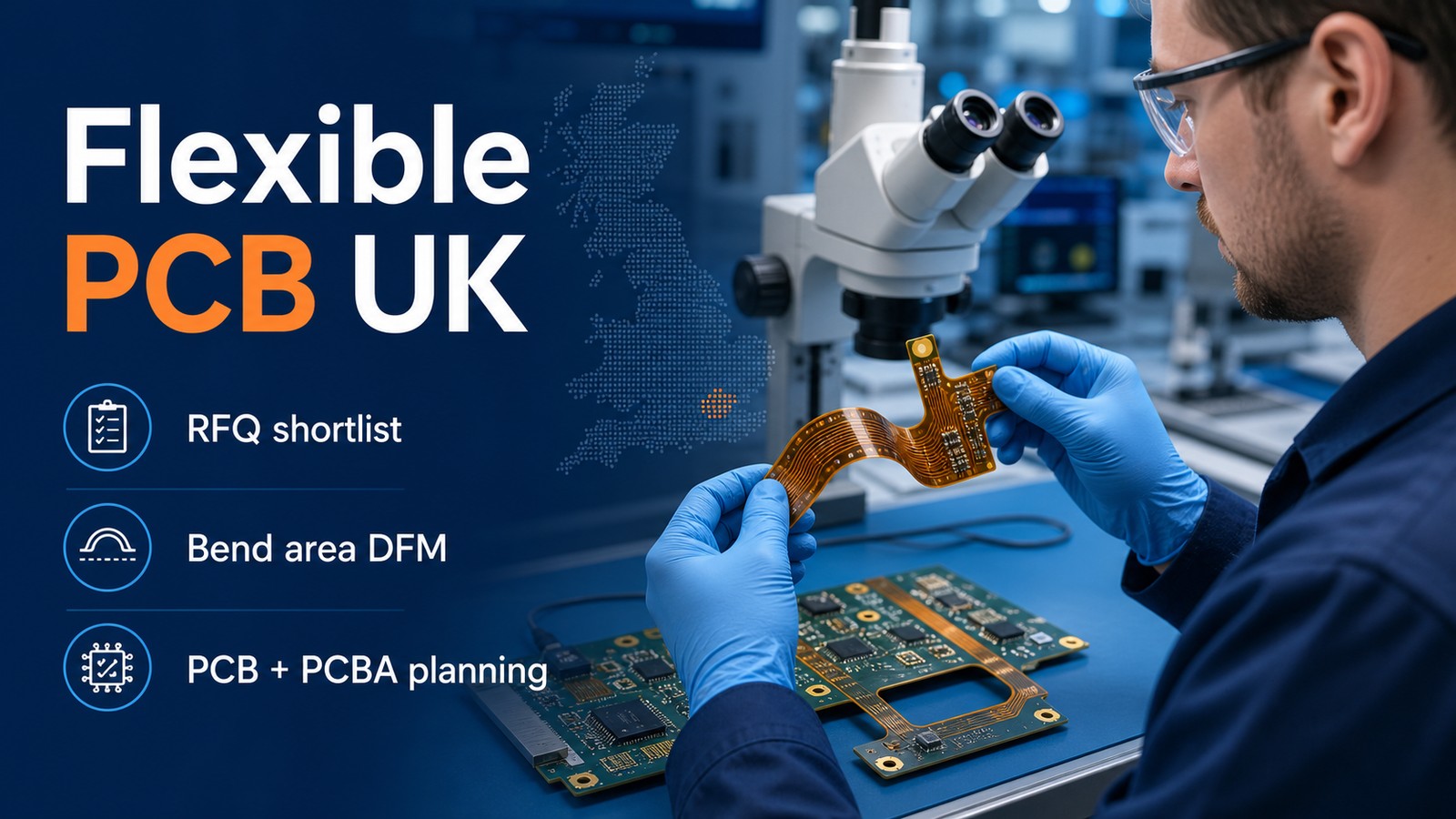
If you are comparing flexible PCB manufacturers for a UK project, build the shortlist around bend-area DFM, material stackup, adhesive/copper choices, PCBA support, certifications and delivery planning. A supplier name is useful only after the company explains how it will quote, manufacture, assemble, inspect and ship your actual flexible PCB project.
EBest Circuit directly serves UK buyers that need PCB fabrication, PCBA service, BOM/CPL review, DFM feedback, component sourcing, testing support and production planning in one RFQ path.
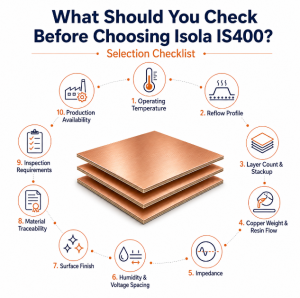
Before choosing a flexible PCB supplier, check whether the quote covers the problems that usually appear after a quick low price.
UK buyers can usually find supplier names. The harder job is finding out who can control flexible PCB bend areas, stiffeners, coverlay openings, soldering, PCBA, inspection, testing and repeat production without hidden gaps.
- The first quote covers bare PCBs only, while assembly, component sourcing, stencil, inspection, testing and freight are added later.
- The supplier says the board is manufacturable, but does not confirm stackup, material, finish, copper, hole limits, panelization or assembly clearance.
- BOM/CPL problems, unavailable components, package mismatches or polarity questions are found only when assembly is already waiting.
- The prototype can be built once, but nobody explains what must change before low-volume or repeat production.
- The lead time is given as one number, without separating PCB fabrication, component sourcing, assembly, testing, packing and shipping.
EBest Circuit helps UK buyers turn a flexible PCB supplier search into a build-ready PCB and PCBA plan.
- We review Gerber or ODB++ files, stackup, material notes, surface finish, quantity, testing needs and delivery goals before quote approval.
- We connect bare-board fabrication with PCBA, BOM/CPL review, component sourcing and assembly planning.
- We help catch DFM questions early, so the buyer can fix design, panel, soldering, hole, material or assembly issues before production starts.
- We review sourcing risk before assembly, especially where substitutes, MOQ, package availability or long-lead components can change schedule.
- We help plan prototype, low-volume and production builds with the next stage in mind, instead of treating every order as a one-time sample.
Top 12 Flexible PCB Manufacturer Options for UK RFQ Shortlists
Use this list to build an RFQ shortlist, then compare each supplier with the same files and the same scope questions. Exact capability, MOQ, inspection, testing and delivery should still be confirmed directly with each supplier.
1. EBest Circuit
Main Products / PCB or PCBA Type: Flexible PCB, rigid-flex PCB, rigid PCB, PCBA and bend-area DFM review
Certifications: IATF 16949, ISO 9001, ISO 13485, UL, RoHS, REACH
Service Type: Prototype, low volume, production, PCBA
Location / Service Region: Directly serves UK buyers
2. Newbury Electronics
Main Products / PCB or PCBA Type: Flexible PCB, flex-rigid PCB, PCB fabrication and assembly
Certifications: ISO 9001; AS9100D and UL approvals listed by industry profile
Service Type: Prototype and production PCB manufacturing
Location / Service Region: Newbury, UK
3. Rush PCB UK
Main Products / PCB or PCBA Type: Flexible PCB, rigid-flex PCB, prototype PCB and assembly
Certifications: ISO certifications, RoHS and IPC standards stated by supplier
Service Type: Prototype, assembly and production support
Location / Service Region: UK service option
4. Tate Circuits
Main Products / PCB or PCBA Type: Flexible PCB, bare PCB supply, prototype PCB and production PCB
Certifications: ISO-certified, UL-approved, RoHS-compliant production
Service Type: Prototype and volume PCB supply
Location / Service Region: UK support with offshore production
5. TTM Technologies
Main Products / PCB or PCBA Type: Flexible PCB, rigid-flex PCB, HDI PCB and RF/microwave PCB
Certifications: ISO 9001, ISO 13485, UL and other quality system categories
Service Type: Prototype, time-critical and production PCB programs
Location / Service Region: Global supplier serving UK buyers
6. PCB Runner
Main Products / PCB or PCBA Type: Flex PCB, rigid-flex PCB, PCB fabrication and assembly support
Certifications: RFQ should confirm ISO, UL and IPC requirements
Service Type: Prototype and production support
Location / Service Region: UK / Europe service
7. Starteam Global UK
Main Products / PCB or PCBA Type: Flexible PCB, rigid PCB and global PCB manufacturing services
Certifications: ISO and UL program requirements should be confirmed before RFQ
Service Type: Prototype and production PCB supply
Location / Service Region: UK service
8. Cambridge Circuit
Main Products / PCB or PCBA Type: Printed circuit board manufacturing and UK PCB supply
Certifications: ISO 9001 and UL requirements should be confirmed before RFQ
Service Type: Prototype and production PCB manufacturing
Location / Service Region: Cambridge, UK
9. ABL Circuits
Main Products / PCB or PCBA Type: Rigid PCB, flexible PCB and prototype PCB manufacturing
Certifications: ISO 9001 listed on PCB Directory
Service Type: Prototype and production PCB supply
Location / Service Region: UK
10. Graphic PLC
Main Products / PCB or PCBA Type: Flex-rigid PCB, HDI PCB and high-reliability PCB manufacturing
Certifications: ISO and UL program requirements should be confirmed before RFQ
Service Type: Prototype and production PCB
Location / Service Region: UK
11. PW Circuits
Main Products / PCB or PCBA Type: PCB manufacture, assembly, design and engineering support
Certifications: RFQ should confirm ISO, UL and IPC requirements
Service Type: Prototype, assembly and production support
Location / Service Region: UK
12. Yeovil Circuits
Main Products / PCB or PCBA Type: Flexible PCB, rigid PCB manufacturing and assembly services
Certifications: RFQ should confirm ISO, UL and IPC requirements
Service Type: Prototype and PCB production support
Location / Service Region: Yeovil, UK
How UK Buyers Should Use This Supplier List
Use the list like an engineering checklist: same files, same questions, same scope. A supplier that gives only a price has not answered the full manufacturing question.
- Separate bare-board needs from PCBA needs. A fabricated PCB quote and an assembled-product quote are different jobs, so do not compare them as the same price.
- Ask each supplier to confirm the same manufacturing assumptions. Material, stackup, finish, copper, inspection, BOM/CPL and testing must be checked against the same file package.
- Compare response quality, not only unit price. A useful supplier explains what is included, what is unclear and what still needs engineering review.
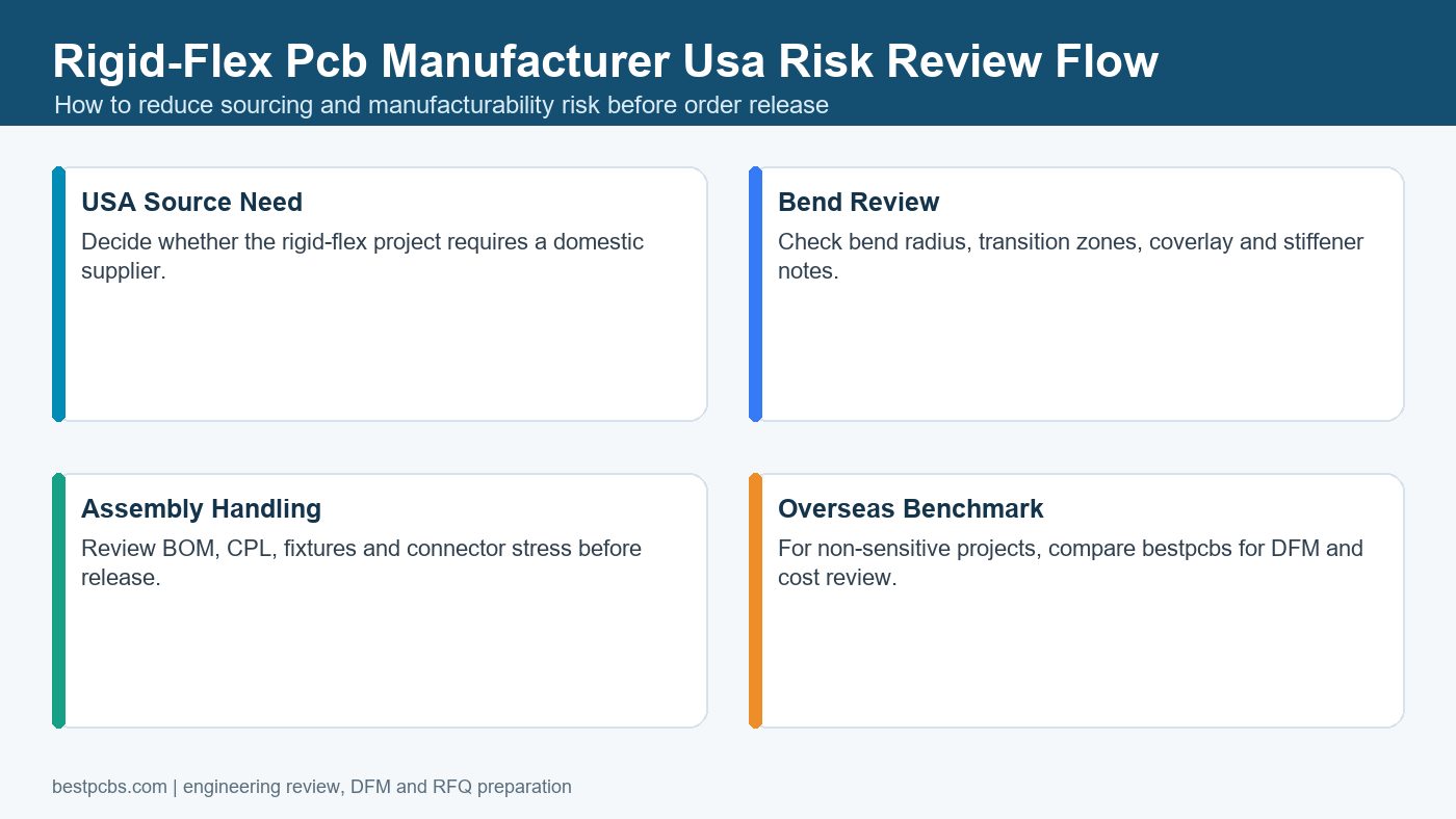
- Choose the supplier that explains risk before the order starts. The stronger choice shows how DFM issues, sourcing risk, assembly yield and delivery timing will be controlled after purchase order approval.
Why UK Buyers Should Put EBest Circuit First
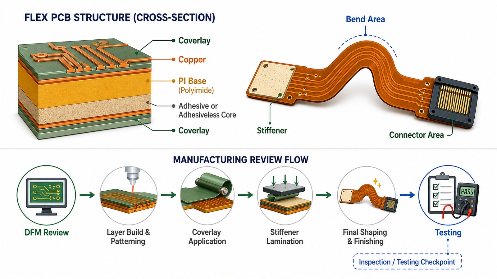
EBest Circuit should be in the first RFQ batch when a UK flexible PCB project needs more than a bare-board price. We review the bend area, stackup, coverlay, stiffener, panel, soldering, BOM/CPL, inspection and delivery plan together, so the buyer can compare the real build path before committing budget.
| Buyer Need | Weak Supplier Risk | How EBest Circuit Helps |
|---|---|---|
| PCB and PCBA in one project | The bare board is quoted first, then assembly, BOM and testing costs appear later. | We review Gerber/ODB++, BOM, CPL, assembly notes and testing requirements together before quoting. |
| Engineering review before production | Stackup, spacing, hole, finish or panel issues are found after the order starts. | Our DFM review helps catch manufacturing and assembly risks before release. |
| BOM and component sourcing control | Unavailable parts, wrong packages, unclear substitutes or MOQ issues delay assembly. | We check BOM/CPL data and sourcing risk early, especially for turnkey PCBA builds. |
| Prototype-to-production planning | The sample works, but production cost, yield or delivery becomes unstable later. | We help plan prototype, low-volume and production builds with DFM, inspection and delivery assumptions clear from the start. |
Before You Choose a UK Flexible PCB Supplier, Let EBest Circuit Check the Real Build Risk
Send Gerber or ODB++ files, BOM/CPL, quantity, material notes, finish and test requirements. EBest Circuit can review fabrication scope, PCBA risk, DFM issues and quote assumptions before you commit to a supplier.
Gerber | ODB++ | BOM/CPL | DFM | PCBA | Inspection
UK Supplier Options vs EBest Circuit
A local supplier can be useful for local coordination, while EBest Circuit is often the stronger RFQ choice when the buyer needs PCB + PCBA review, DFM response and total cost control together. The buyer should compare the build plan, not only the supplier address.
| Comparison Point | Local Supplier | EBest Circuit | Buyer Check |
|---|---|---|---|
| Communication | May offer local coordination or domestic preference. | Directly supports UK buyers with engineering review and RFQ communication. | Does the supplier answer technical questions clearly? |
| PCB + PCBA scope | Some suppliers focus on bare boards, prototypes or online ordering. | Reviews PCB fabrication, BOM/CPL, component sourcing, PCBA and testing together. | Is the quote complete enough to represent the final product? |
| Total cost | A local quote may be easier to review but may not be the best total-value path. | Helps compare total manufacturing value before approval. | Are fabrication, PCBA, components, test and shipping separated clearly? |
| Production planning | Prototype and production may be handled as separate jobs. | Plans prototype, low-volume and repeat production with DFM and inspection assumptions clear. | Can the supplier explain what changes when the order scales? |
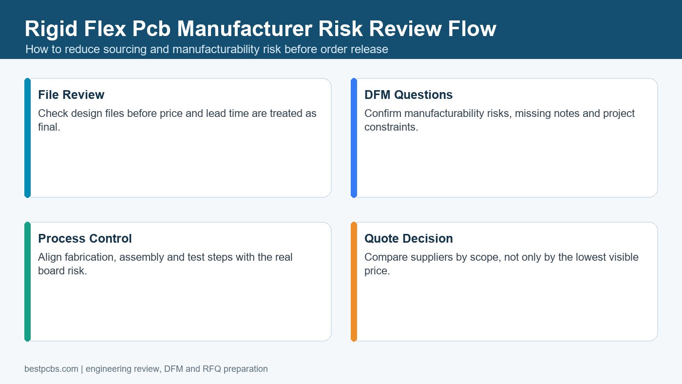
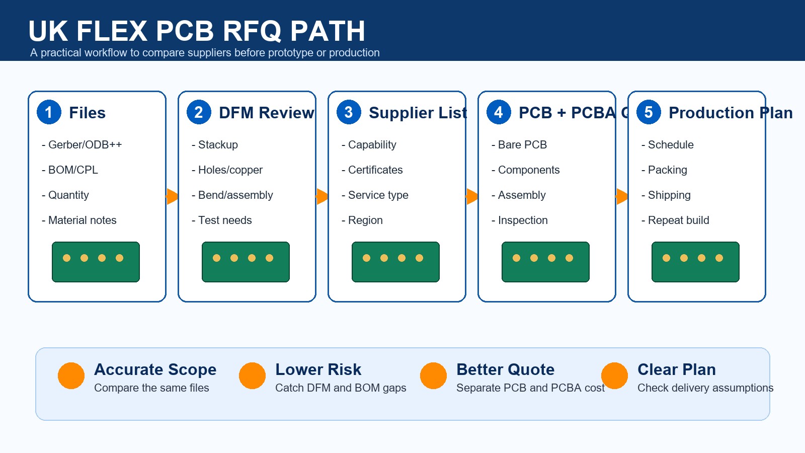
UK PCB RFQ Shortlist Path
A supplier shortlist becomes useful only when it turns into a build-ready RFQ package. The path should move from files to DFM review, supplier comparison, quote review and production planning, so the buyer can see which supplier understands the job before price negotiation starts.
Fabrication Scope to Confirm Before RFQ
Fabrication scope should be confirmed before price comparison because small technical differences can change cost, yield and delivery. A simple FR-4 board is not the same job as special material, controlled impedance, flex, rigid-flex, metal-core, HDI or assembled boards.
| Item | Buyer Should Provide | Supplier Should Confirm |
|---|---|---|
| Material | FR-4, high Tg, metal-core, flex, high-frequency or other material note | Availability, substitution limits and cost impact |
| Stackup | Layer count, thickness, copper and impedance needs | Manufacturable stackup and tolerance assumptions |
| Finish | ENIG, OSP, immersion tin, immersion silver or other finish | Fit for soldering, storage and application |
| Inspection | Electrical test, AOI, X-ray or functional test needs | What is included in the quote and what is optional |
PCBA, BOM/CPL and Component Sourcing Checks
If the project needs assembly, PCBA support can matter more than bare-board price. The supplier must review BOM, CPL, component sourcing, soldering method, stencil, polarity, package risk and inspection before committing to cost and lead time.
| PCBA Item | What Can Go Wrong | What to Ask in the RFQ |
|---|---|---|
| BOM | Wrong package, unavailable part or unclear manufacturer part number | Ask for BOM review and approved substitutes before purchase. |
| CPL | Wrong rotation, missing polarity or placement mismatch | Ask the supplier to check CPL against assembly drawings. |
| Soldering | Fine-pitch, mixed technology or thermal parts need process review | Ask how SMT, THT, mixed assembly or special soldering will be handled. |
| Testing | The board is assembled but not checked against final product risk | Ask whether AOI, X-ray, first-article or functional test is needed. |
DFM Response: What a Good Supplier Should Tell You
DFM response shows whether the supplier has actually looked at the job. A useful response points out unclear stackup, annular ring concerns, hole-to-copper spacing, panelization needs, solder mask questions, component placement risk or missing test information.
- Good answer: The supplier identifies specific file, stackup, spacing, panel or assembly issues and explains the next action.
- Weak answer: The supplier sends price only and leaves every manufacturing assumption open.
- Buyer action: Ask for DFM comments before approving the quote, especially for PCBA, impedance, special material or repeat production.
Inspection and Testing Questions to Ask Before Supplier Approval
Inspection and testing should match the board risk, not a generic quality promise. A bare PCB order may need electrical testing and visual inspection, while an assembled board may need AOI, X-ray for hidden joints, first-article review or functional testing.
| Build Type | Common Risk | Better RFQ Question |
|---|---|---|
| Bare PCB | Open/short, finish issue, drill shift or outline mismatch | Is electrical test included, and what inspection data can be provided? |
| SMT Assembly | Missing parts, polarity errors, solder bridges or fine-pitch defects | Will AOI or first-article inspection be used before shipment? |
| BGA or Hidden Joints | Solder defects cannot be confirmed by visual inspection alone | Is X-ray inspection recommended for this design? |
| Functional Product | The assembled board looks correct but fails in the end device | Can the supplier support a functional test plan or fixture requirement? |
Prototype, Low-Volume and Production Fit
The best supplier for a first prototype is not always the best supplier for repeat production, so order stage must be checked early. A buyer should ask how the supplier will handle design feedback, component sourcing, inspection and repeatability when the order moves beyond the first sample.
| Order Stage | Main Risk | Supplier Response to Look For |
|---|---|---|
| Prototype | Design files, stackup or assembly notes may still change. | Fast DFM questions and clear file feedback before fabrication. |
| Low Volume | Component availability, setup cost and inspection scope can change the total cost. | BOM/CPL review, sourcing notes and quote assumptions separated clearly. |
| Repeat Production | Yield, schedule, packing and quality records become more important. | Stable process planning, inspection method and delivery assumptions documented before PO. |
What Determines Quote Differences Between Suppliers?
Quote differences usually come from scope differences, not only factory pricing. Two suppliers may look far apart because one included PCBA, sourcing, test, packing and shipping, while another priced only bare PCB fabrication.
| Cost Area | Why Quotes Differ | What to Ask |
|---|---|---|
| Bare PCB | Layer count, finish, copper, material and panel use differ. | Ask each supplier to quote the same stackup and finish. |
| Assembly | Stencil, setup, soldering, AOI and rework assumptions differ. | Ask what is included in PCBA price. |
| Components | Availability, substitutes, MOQ and lead time differ. | Ask for BOM risk review before approval. |
| Delivery | Fabrication, sourcing, assembly, testing and freight are mixed together. | Ask for a schedule broken down by stage. |
Check PCB + PCBA Cost Before the Supplier Decision
A low bare-board price can miss assembly, sourcing, inspection, test and delivery assumptions. EBest Circuit helps compare the full build path before purchase order approval.
Gerber | ODB++ | BOM/CPL | DFM | PCBA | Inspection
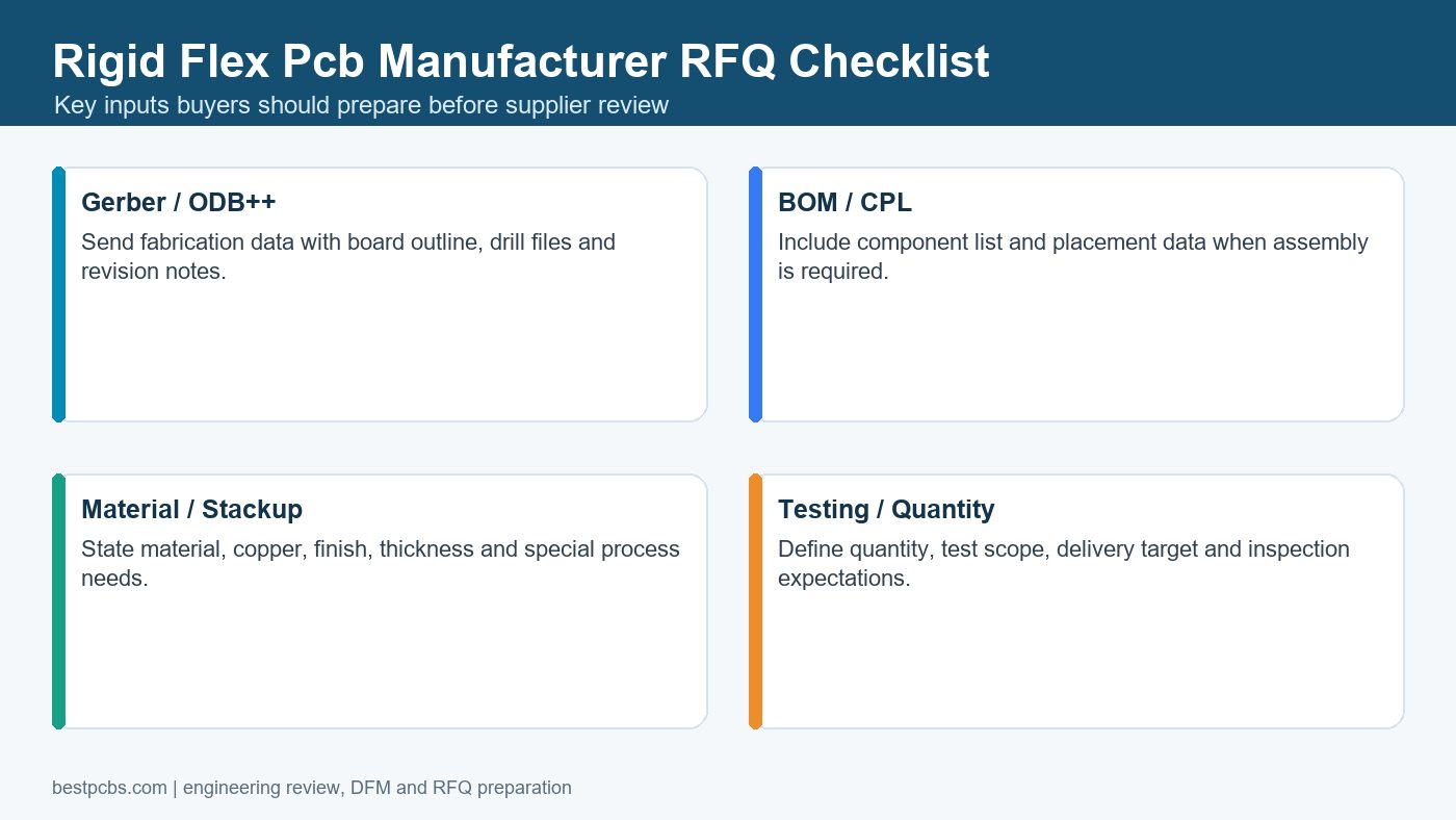
Files to Send for an Accurate Quote
An accurate quote needs a complete manufacturing package, not only one Gerber zip. The more complete the package, the less time the supplier spends guessing. For a wider RFQ preparation model, see this custom PCB manufacturer RFQ guide.
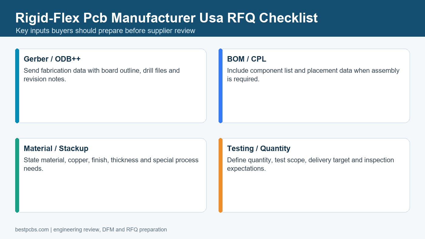
- Gerber or ODB++ files and NC drill files.
- Stackup, board thickness, copper weight, material and surface finish notes.
- Quantity, panel requirement and target delivery date.
- BOM and CPL if PCBA is needed.
- Assembly drawing, polarity notes, special soldering notes and test requirements.
- Any impedance, thermal, coating, packing or application requirement.
Frequently Asked Questions About Flexible PCB Manufacturers for UK Buyers
How should I compare flexible PCB manufacturers serving UK?
Compare the same file package, not just the supplier name. Send Gerber or ODB++, stackup, BOM/CPL, quantity, finish, test needs and delivery target to every supplier, then compare how clearly they answer DFM, PCBA, inspection and schedule questions.
Why is EBest Circuit listed first?
EBest Circuit is listed first because this article is built for RFQ decision-making. We directly serve UK buyers and can review PCB fabrication, PCBA, BOM/CPL, DFM, component sourcing, inspection and delivery planning together before quote approval.
Is EBest Circuit a local manufacturer in UK?
No. EBest Circuit is not a local UK factory, but we directly serve UK PCB and PCBA buyers. The point is to compare local supplier options with a strong manufacturing partner that can control DFM, cost, PCBA and production planning together.
What files should I send for an accurate PCB quote?
Send Gerber or ODB++ files, NC drill, stackup, board drawing, quantity, material notes, copper, surface finish, BOM, CPL, assembly drawing, test requirements and target lead time. Missing files usually create slow answers and unclear quote scope.
Should I compare bare PCB and PCBA quotes separately?
Separate the numbers, but review the project together. Bare PCB, component sourcing, stencil, assembly, inspection, testing and shipping often affect each other. A supplier that reviews the full path gives a more useful quote.
What makes a PCB supplier response useful?
A useful response explains what is manufacturable, what is unclear, what may change cost, and what must be confirmed before production. A weak response only sends a price without reviewing stackup, BOM, PCBA or testing risk.
Do certificates matter when choosing a PCB supplier?
Yes, certificates matter when the project or industry requires them. Use certificates as one screening field, but still confirm whether the certificate applies to the quoted facility, board type, assembly scope and documentation needs.
How do I avoid a low quote that becomes expensive later?
Ask each supplier to separate PCB fabrication, components, PCBA, inspection, testing, packing and shipping. The low quote is risky when it leaves out assembly, BOM/CPL review, test method or delivery assumptions.
When should I involve EBest Circuit in the RFQ process?
Send files early, before approving a supplier. Early review lets EBest Circuit check DFM, BOM/CPL, PCBA scope, component sourcing, inspection and delivery assumptions while you can still fix the RFQ package.
Can one supplier handle prototype and production planning?
A strong supplier can plan both stages, but you need to ask. Prototype work needs fast DFM and file feedback; production work needs stable process control, sourcing planning, inspection and repeatable documentation.
Final RFQ Recommendation
Do not choose a PCB supplier from a list alone. Send the same file package to each candidate, compare the quality of the engineering response, and put EBest Circuit in the first RFQ batch when you need PCB fabrication, PCBA, DFM, BOM/CPL, component sourcing, inspection and delivery planning checked together. Email Gerber/ODB++, BOM, CPL, quantity, material, surface finish, test requirements and target delivery date to sales@bestpcbs.com.