OAM PCB is the accelerator-module circuit board used to connect high-density AI compute with a server's power, high-speed links, management, and cooling systems. OAM means OCP Accelerator Module; the module normally works with a Universal Base Board (UBB) rather than operating as a stand-alone processor board. This guide shows how the parts fit together, how OAM differs from SXM, and which electrical, thermal, mechanical, fabrication, and assembly requirements matter to a buyer.
EBest Circuit (Best Technology) supports AI accelerator PCB projects with high-layer and HDI fabrication, controlled impedance, component sourcing, BGA assembly, AOI, X-ray inspection, and customer-defined test coordination. If you are evaluating an OAM PCB, send your current board requirements to sales@bestpcbs.com for an initial manufacturability discussion.
What Is an OAM PCB?
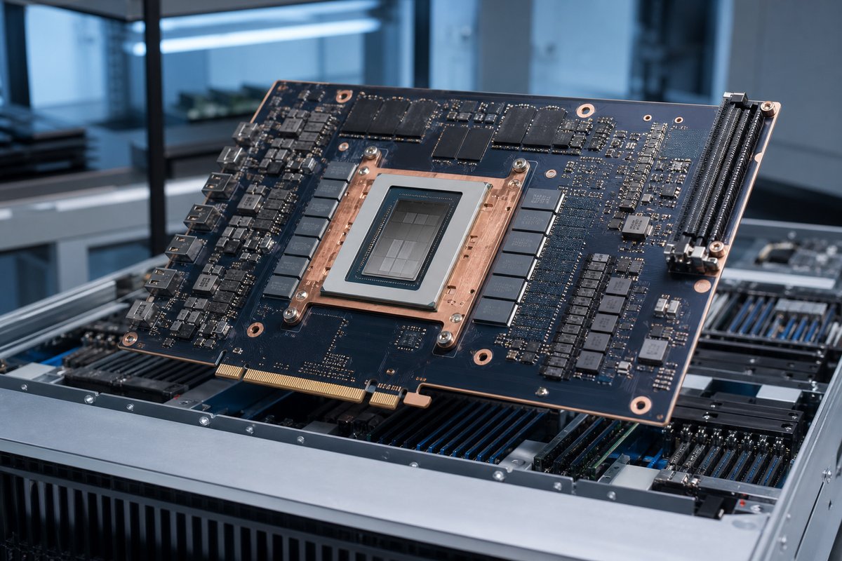
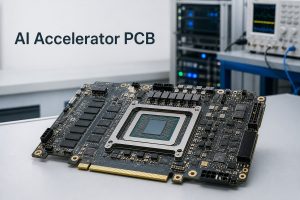
An OAM PCB is the printed circuit board used in an OCP Accelerator Module. It carries an AI accelerator device and the supporting circuitry required to power, manage, connect, and cool that device inside a compatible server platform.
- Compute: a GPU, ASIC, NPU, FPGA, or another parallel processor.
- Local support: memory, voltage regulation, clocks, management devices, and sensors.
- System connection: the connector and mechanical interfaces that link the module to a compatible baseboard and cooling assembly.
OAM defines a form factor and interface framework, not a processor brand or a fixed PCB construction. The actual layer count, materials, vias, components, and tests still depend on the accelerator, power envelope, cooling approach, UBB, and product specification.
How Does an OAM PCB Work in an AI Server?
Inside an AI server, the OAM PCB acts as the local platform for one accelerator. It receives power and management connections from the system, provides the short electrical paths needed around the accelerator and memory, and connects high-speed links to the UBB.
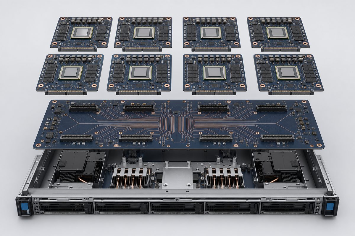
The UBB brings multiple OAM modules together. It distributes power and management signals and provides the physical interconnect fabric between accelerators. Depending on the system architecture, those accelerator-to-accelerator links can support the very high data movement needed for training or inference workloads.
A simplified data path is:
- The host server sends work and data toward the accelerator platform.
- The UBB routes high-speed links, power, and control connections to each OAM module.
- The OAM PCB supports the accelerator, local memory, power conversion, sensing, and module-level interfaces.
- Cooling hardware removes heat from the accelerator and other high-power components.
This division lets the module, baseboard, host, power system, and cooling system be developed as coordinated building blocks. It also means an OAM PCB cannot be evaluated in isolation: its connector geometry, mounting features, power inputs, thermal stack, and high-speed interfaces must match the intended platform.
What Does the OAM Architecture Include?
Although implementations vary, the OAM architecture normally combines several functional groups on one dense PCB.
- Accelerator package: the main GPU, ASIC, NPU, FPGA, or other compute device.
- Local memory: high-bandwidth or other memory devices placed close to the accelerator when required by the processor architecture.
- Power delivery: voltage regulators, inductors, capacitors, current sensing, and power-control circuits that convert the module input into multiple low-voltage rails.
- High-speed interfaces: differential channels connecting the accelerator to other modules, the host, and management resources through the module connector.
- Management and monitoring: controllers, EEPROMs, clocks, temperature sensors, voltage monitors, and service interfaces.
- Mechanical and thermal interfaces: mounting holes, keep-out areas, stiffeners, heatsink contact zones, and the flatness needed for reliable connector engagement and cooling contact.
These groups compete for board area and influence one another. A larger power stage changes copper distribution and thermal behavior. Dense high-speed escape routing can require HDI structures. A heavy heatsink can increase mechanical loading. The architecture must therefore be translated into one coordinated stackup, layout, fabrication, assembly, and cooling plan.
How Do OAM Modules and UBBs Work Together?
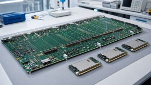
An OAM module is the accelerator board; a UBB is the baseboard that hosts and connects multiple modules. The two boards perform different jobs but operate as one platform.
| Platform part | Primary role | What must match |
|---|---|---|
| OAM module | Carries one accelerator and its local support circuits. | Connector, power, lane map, cooling, and mounting. |
| UBB | Hosts and links multiple OAM modules. | Sockets, routing, current capacity, management, and clearances. |
| AI server | Combines compute, power, cooling, firmware, and software. | Power sequence, thermal capacity, service access, and validation. |
A useful way to picture the relationship is: AI server -> UBB -> multiple OAM modules -> accelerator and local memory on each module.
For example, when eight accelerator modules are installed on one UBB, a connector-position error on one OAM PCB can prevent reliable mating, while an incorrect lane map or channel-loss assumption can affect communication beyond that single module. The OAM and UBB suppliers therefore need controlled interface drawings and the same revision baseline.
OAM vs SXM: What Is the Difference?
OAM and SXM are both used for high-performance accelerator modules, but they come from different platform ecosystems. OAM is associated with the Open Compute Project and is intended to support an open, multi-vendor infrastructure. SXM is a proprietary NVIDIA module format used in selected NVIDIA server platforms.
| Decision area | OAM | SXM |
|---|---|---|
| Ecosystem | Open, OCP/OAI-oriented. | Proprietary NVIDIA platform. |
| Choose when | The system uses an OAM-compatible accelerator and UBB. | The selected NVIDIA platform requires SXM. |
| Baseboard | OAM-compatible UBB. | Designated NVIDIA baseboard. |
| Can they swap? | No; the complete platform must match. | No; the complete platform must match. |
The two formats should not be treated as drop-in replacements. Moving a design from one to the other can affect the module PCB, baseboard, firmware, cooling assembly, power delivery, chassis, and system validation. The form-factor decision belongs at the platform architecture stage, before PCB fabrication data is released.
What Are the PCB Design Requirements for OAM-Compatible Systems?
An OAM-compatible system must carry fast signals, high current, dense packages, and substantial thermal and mechanical loads at the same time. The PCB design requirements are therefore interconnected.
- Stackup and materials must support the required channel loss, impedance, layer count, thickness, and fabrication capability.
- Differential pairs need controlled geometry, continuous reference planes, suitable spacing, and a via strategy that limits discontinuities.
- Large packages and dense connectors may require blind or buried vias, microvias, via-in-pad, filled vias, and back drilling.
- Power and ground structures must carry the module current while controlling voltage drop, noise, and localized heating.
- Copper distribution and layer construction must support board flatness and reduce assembly warpage risk.
- Connector footprints, mounting holes, heatsink interfaces, keep-outs, and board edges must follow the mechanical definition of the target platform.
The most useful design review looks at the complete path: accelerator package breakout, on-module routing, connector launch, UBB routing, and the destination device. A locally correct trace can still fail if the combined channel exceeds its loss or discontinuity budget.
What Power and Thermal Requirements Shape an OAM PCB?
OAM PCBs combine high power density with strict mechanical and signal-integrity requirements. Power and thermal design therefore shape the physical PCB, not just the component selection.
| Requirement group | What shapes the PCB | What the customer must define |
|---|---|---|
| Power | Planes, copper, vias, decoupling, and regulator layout. | Input power, rail current, voltage drop, transients, and sequence. |
| Thermal | Heat spreading, component spacing, and cooler interface. | Cooling method, contact area, temperature limits, and test conditions. |
| Mechanical | Thickness, stiffeners, mounting, alignment, and flatness. | Datums, mounting load, keep-outs, tolerances, and tray limits. |
These requirements must be reviewed together. More copper may improve current capacity but can change etching, lamination, impedance geometry, flatness, and reflow behavior. A large cooling assembly may remove heat effectively but still create board strain if the mounting stack is not coordinated.
The PCB manufacturer can review manufacturability and material implications, but final power integrity, cooling design, and server validation remain system responsibilities.
How Are PCBs Fabricated and Assembled for OAM Modules?
OAM modules are commonly advanced multilayer assemblies, but the exact process should follow the released design rather than a generic OAM recipe.
- Fabrication review: confirm materials, copper, impedance geometry, via structure, lamination, registration, back drilling, thickness, flatness, and finish.
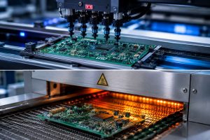
- Assembly planning: account for large BGAs, memory, power components, connector coplanarity, thermal mass, moisture control, paste, placement, and reflow.
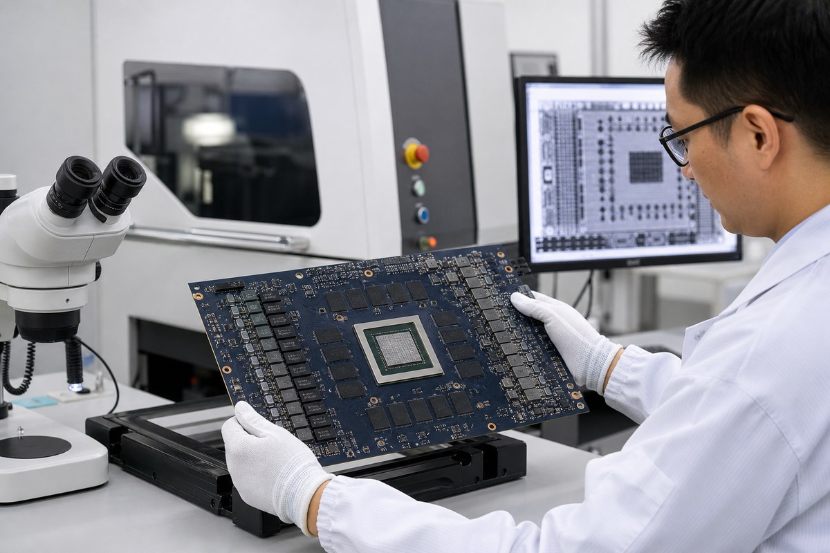
- Verification plan: select bare-board electrical test, impedance testing, SPI, AOI, X-ray, dimensional checks, and customer-defined functional tests according to the real risks.
No single inspection method proves the whole module. The evidence plan should match the likely failure modes and the test points that are actually accessible.
EBest Circuit (Best Technology) can support manufacturability review, material coordination, PCB fabrication, component sourcing, BGA assembly, AOI, X-ray inspection, and customer-defined testing coordination. Accelerator architecture, firmware, system cooling, regulatory compliance, and final server qualification remain with the customer and its platform partners.
Where Is OAM PCB Technology Used?
OAM PCB technology is used where systems need dense, modular accelerator computing. The most visible applications are AI training servers and high-performance computing platforms, but the same infrastructure can also support inference, data analytics, scientific computing, and other workloads built around compatible accelerator modules.
- AI training servers that need several tightly connected accelerator modules.
- High-performance computing clusters handling scientific or engineering workloads.
- Cloud and enterprise AI infrastructure designed around serviceable accelerator trays.
- Inference and data-analytics platforms that benefit from dense modular compute.
- Specialized compute appliances built around an OAM-compatible accelerator ecosystem.
OAM is not automatically the best format for every AI product. PCIe cards may be simpler for lower-power or broadly compatible add-in acceleration, while embedded modules may fit edge systems with tighter space and power limits. OAM becomes most relevant when the platform benefits from high accelerator density, strong module-to-module communication, serviceable modular hardware, and coordinated power and cooling.
How to Choose an OAM PCB Manufacturer?
An OAM PCB manufacturer should be evaluated against the released board requirements, not against a generic list of advanced capabilities.
| Evaluation stage | What to confirm | Why it matters |
|---|---|---|
| 1. Platform fit | Understands the OAM/UBB interface and board requirements. | Prevents interface assumptions from reaching production. |
| 2. Process fit | Covers the required HDI, impedance, assembly, and inspection steps. | Keeps fabrication and assembly decisions aligned. |
| 3. Build control | Controls material, stackup, BOM, files, and test revisions. | Reduces prototype-to-production revision drift. |
The best supplier is not necessarily the one that claims the highest layer count. It is the one that can explain how the specific OAM design will be built, where its process margins are tight, what evidence will be delivered, and which responsibilities remain with the system developer.
For project-specific review, send the released Gerber or ODB++ data, stackup, fabrication drawing, BOM, placement data, assembly drawing, connector and mechanical definitions, and test requirements to sales@bestpcbs.com.
FAQs About OAM PCB
What does OAM mean in PCB hardware?
OAM means OCP Accelerator Module. In PCB hardware, it describes an accelerator-module form factor and interface framework developed in the Open Compute Project ecosystem.
Is an OAM PCB the same as a UBB?
No. The OAM PCB carries one accelerator module. The Universal Base Board hosts and connects multiple OAM modules and provides shared interconnect, power, management, and mechanical integration.
Is OAM the same as NVIDIA SXM?
No. Both are accelerator-module formats, but OAM belongs to an open OCP/OAI ecosystem while SXM is a proprietary NVIDIA platform. Their interfaces and system requirements are not interchangeable.
Why are OAM PCBs difficult to manufacture?
They can combine high layer counts, low-loss materials, HDI vias, dense high-speed routing, high-current power structures, large BGA packages, strict flatness, and demanding thermal hardware on one assembly.
What should be reviewed before building an OAM PCB?
Review the platform specification, board and UBB revisions, stackup, impedance and loss targets, via structure, power inputs, connector and mechanical definitions, thermal stack, BOM, assembly data, and inspection and test requirements.
Planning an OAM PCB or another AI accelerator PCB? Send your current design package or project questions to sales@bestpcbs.com. EBest Circuit (Best Technology) can review the PCB fabrication, sourcing, assembly, inspection, and customer-defined test scope for your build.
You may also like




Tags: ai accelerator pcb, OAM module, OAM PCB