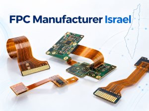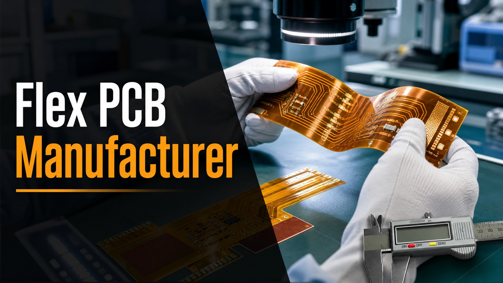
A flex PCB manufacturer should help you turn flexible circuit requirements into a buildable, testable and repeatable board, not only quote a thin orange circuit. For buyers, the key decisions are material, copper thickness, bend area, coverlay, stiffener, connector support, assembly method, inspection plan and the RFQ files needed before production starts.
EBest Circuit supports flexible PCB and rigid-flex PCB projects where buyers need DFM review, material confirmation, PCB fabrication, PCBA support, component sourcing and clear production planning. If your project has a bend area, moving section, connector tail, tight enclosure or mixed rigid-flex structure, the supplier should review the mechanical and electrical risks before committing to cost or lead time.
Before approving a flex PCB quote, are these risks already clear?
Flexible circuits fail most often when the quote is based only on Gerber files and quantity. The buyer may not see the risk until the first samples crack, lift, delaminate or fail in assembly.
- The bend area is routed like a rigid board, with copper, vias or stiffener edges placed where the circuit must flex.
- The material stackup is not matched to static bend, dynamic bend, thickness, copper weight and enclosure space.
- Coverlay openings, adhesive flow, solder mask choices or stiffener locations are not reviewed before tooling.
- The connector area looks fine in CAD, but the finished flex tail lacks enough support for insertion, soldering or repeated handling.
- The buyer asks for a fast quote, but the supplier cannot confirm whether special PI, copper, stiffener or surface finish choices need purchasing review.
EBest Circuit reviews the flex circuit as a manufacturing and assembly problem, not just a board outline.
- We review Gerber or ODB++ files, stackup, bend drawings, material notes, copper, coverlay, stiffener, finish and quantity together.
- We check whether the flexible area, connector area, component area and rigid support area match the real use of the product.
- We help buyers identify missing files such as bend direction, stiffener drawing, assembly drawing, BOM, CPL and test requirements.
- We can connect flex PCB fabrication with PCBA support when the project needs soldering, component sourcing, inspection or production planning.
- We keep special material and process items conditional until the project files are reviewed, so the quote does not pretend that every flex design is the same.
What Should a Flex PCB Manufacturer Help You Decide First?
A flex PCB manufacturer should first help you decide whether the circuit is a simple static flex, a dynamic bending flex, or a rigid-flex project with mechanical support requirements.
This decision affects nearly everything else: PI thickness, copper weight, adhesive or adhesiveless core, coverlay, bend radius, stiffener placement, panel design, assembly method and testing. A supplier that only asks for Gerber files may return a price quickly, but the price may not include the engineering questions that decide whether the finished circuit survives in the product.
For a buying team, the first useful answer is not “yes, we can build flex PCB.” The useful answer is: what design details need confirmation before the board is safe to quote, fabricate and assemble?
Is EBest Circuit a Fit for Your Flex PCB Project?
EBest Circuit is a practical fit when your flex PCB project needs engineering review, material confirmation, fabrication planning, optional assembly support and clear RFQ communication.
Typical fit includes flexible circuits for compact electronics, connector tails, LED-related electronics, industrial control products, communication devices, medical electronics, consumer electronics and small-to-medium batch projects. The strongest fit is a project where the buyer can send fabrication files together with drawings, material notes, BOM, CPL and testing requirements.
If the project is still early, EBest Circuit can help review the RFQ package before assumptions become fixed. If the project is moving from prototype to repeat production, our team can help connect flex fabrication questions with assembly, sourcing and inspection planning.
Flex PCB Manufacturing Capabilities Buyers Should Check
Buyers should check layer count, board thickness, minimum flex width, material options, line and spacing, drilling, coverlay, stiffener and surface finish before choosing a flex PCB manufacturer.
| Capability Area | What to Confirm | EBest Circuit Evidence Basis |
|---|---|---|
| Layer count | Simple flex, multilayer flex or rigid-flex structure | Rigid-flex entries list 2-20 layers; flex layer entries list 2-10 layers, with HDI items requiring project confirmation |
| Board thickness | Finished thickness and tolerance | Rigid-flex table lists 0.3-3.0 mm board thickness examples |
| Flex width | Minimum flex tail or bend section width | Table lists 2.0 mm minimum flex width |
| Material | PI, copper, adhesive or adhesiveless core | Shengyi, Panasonic, DuPont and Thinflex options appear in the source table, with special materials requiring confirmation |
| Coverlay and stiffener | Opening, adhesive, support and connector reinforcement | Coverlay and PI stiffener entries are listed; special options require review |
| Line and space | Copper thickness, bend area and layer position | External flex-layer line/space examples include 5.0/4.5 mil at 18um copper and wider values for thicker copper |
These values are not a substitute for file review. They are useful screening points for deciding whether the design should be quoted as standard, special process or “confirm before quote.”
Flexible PCB Materials: PI, Copper, Adhesive and Adhesiveless Cores
Flex PCB material choice should match bend use, thickness, copper weight, thermal exposure, assembly process and cost target.
Common flexible circuits use polyimide film with copper foil and either adhesive or adhesiveless construction. Adhesive flex cores can be suitable for many standard products. Adhesiveless cores are often considered when the project needs better dimensional stability, thinner construction or improved reliability under certain stress conditions. The correct choice depends on the design, bend area, copper pattern, assembly temperature and expected product use.
EBest Circuit’s FPC and rigid-flex capability source includes PI and copper material entries from suppliers such as Shengyi, Panasonic, DuPont and Thinflex. Some special materials are marked as non-routine or requiring purchasing confirmation, so public claims should stay conditional until the exact material and quantity are reviewed.
Coverlay, Stiffeners and Connector Areas
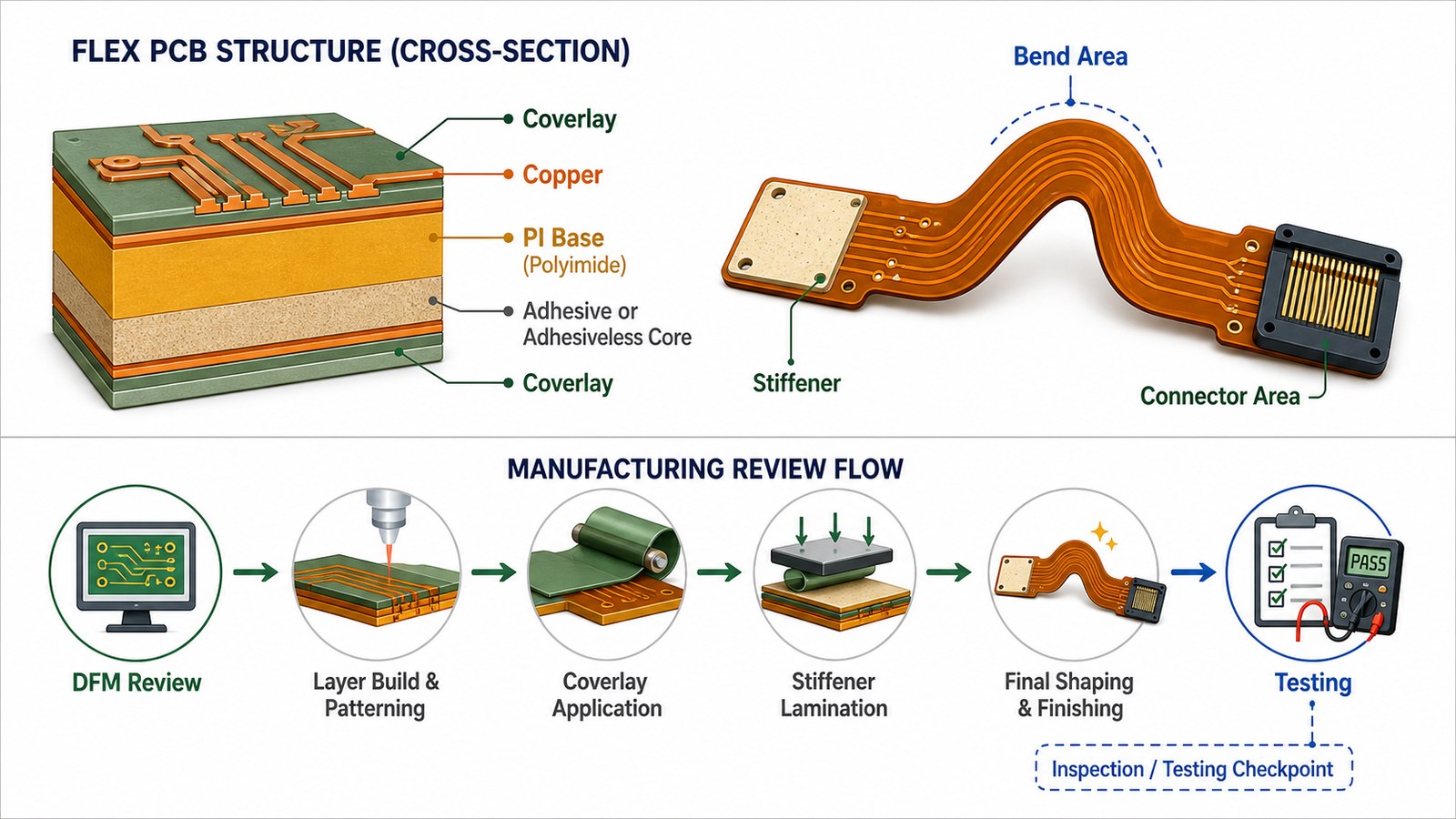
Coverlay protects flexible copper areas, while stiffeners support connectors, components and handling zones that should not bend.
Coverlay is not the same as rigid PCB solder mask. It must be opened, aligned and bonded in a way that protects the flex circuit while leaving solder pads, connector fingers or exposed areas usable. Poor coverlay design can create cracks, lifting, registration problems or soldering issues.
Stiffeners are often used under connectors, soldered parts, ZIF tails or mechanical handling points. EBest Circuit’s source table includes PI stiffener entries such as 3 mil, 5 mil, 7 mil and 9 mil. The right stiffener depends on connector type, insertion force, tail thickness, assembly process and available space.
Bend Area Design and Reliability Risks
The bend area should keep copper stress low, avoid vias and sharp transitions, and separate flexible movement from rigid support zones.
A flexible PCB can fail even when the bare board passes electrical test if the bend area is poorly designed. Avoid placing vias, plated holes, sharp copper corners, stiffener edges or component solder joints inside the active bend. Copper traces should flow smoothly through the bend, and the bend direction should be clear in the drawing.
For dynamic bend applications, the manufacturer needs more information than a static board outline. Bend radius, cycle expectation, enclosure movement, installed shape and stress direction can affect material and layout advice. If those details are missing, the quote may look complete while the reliability risk remains unresolved.
Rigid-Flex vs Flexible PCB: Which Supplier Path Fits?
Use a flexible PCB when the circuit mainly needs a bendable interconnect; use rigid-flex when rigid component areas and flexible connections must become one integrated structure.
A simple flexible PCB may be the right choice for a connector tail, sensor lead, display connection or compact interconnect. A rigid-flex PCB becomes more useful when the product needs rigid component zones joined by controlled flexible sections. Rigid-flex can reduce connector count and assembly steps, but it usually increases stackup, lamination and DFM complexity.
If your design sits between the two options, send the mechanical constraints early. EBest Circuit can review whether the design should stay as flex, move to rigid-flex, or use a rigid board plus cable approach.
Need a flex PCB quote that checks bend and assembly risk?
Send Gerber or ODB++ files, stackup, bend drawing, stiffener notes, BOM, CPL, quantity and test requirements. EBest Circuit can review the manufacturing path before quoting.
Gerber or ODB++ | Bend drawing | Coverlay | Stiffener | BOM and CPL
DFM Review Before Flex PCB Manufacturing
DFM review should check whether the flexible circuit can be fabricated, bent, assembled and tested without hidden mechanical or electrical risk.
Important DFM checks include bend direction, copper orientation, trace width and spacing, coverlay opening, pad support, stiffener edge clearance, connector tail thickness, panelization, fiducials, tooling holes, surface finish and assembly access. If the design has components on or near the flexible section, DFM should also review soldering stress and handling risk.
Buyers should treat DFM as part of quotation, not a late production formality. A cheaper quote that skips bend and stackup review can become more expensive after tooling changes, sample failure or assembly rework.
Flex PCB Assembly, Component Sourcing and PCBA Support
Flex PCB assembly requires more care than rigid-board assembly because handling, support, thermal exposure and connector areas can affect yield.
If the flexible board carries components, the supplier should review whether temporary carriers, fixtures, stiffeners or panel rails are needed during SMT or through-hole operations. Component placement should avoid active bend zones unless the design is specifically engineered for that condition.
EBest Circuit can connect flex fabrication with PCBA and PCB assembly support, component sourcing and the flex PCB assembly quote path. This helps buyers avoid separating board fabrication questions from BOM, CPL, soldering and test questions.
Testing and Quality Checks for Flexible Circuits
Testing for flexible circuits should confirm both electrical continuity and manufacturing details that affect bending, assembly and connector reliability.
Electrical test can confirm open and short conditions, but it does not prove that a bend area is mechanically safe. Buyers should also consider visual inspection, dimensional checks, coverlay registration, stiffener alignment, connector pad condition, solderability, impedance requirements and assembly inspection. When components are assembled, AOI, X-ray, ICT or functional testing may be relevant depending on package type and product risk.
For projects with special reliability expectations, define the test method in the RFQ. Do not assume that every supplier includes the same inspection or functional test scope in a base price.
What Affects Flex PCB Manufacturing Cost?
Flex PCB cost is mainly affected by material, layer count, copper, coverlay, stiffener, bend requirements, size, testing, assembly scope, quantity and special process confirmation.
| Cost Factor | Why It Changes the Quote | Buyer Action |
|---|---|---|
| Material | PI type, copper thickness and adhesive or adhesiveless core affect sourcing and process | Send required material or allow engineering review |
| Bend requirement | Dynamic bend needs more design review than static installation bend | Provide bend radius, direction and cycle expectation if known |
| Coverlay and stiffener | Openings, bonding and reinforcement affect tooling and labor | Send coverlay and stiffener drawings |
| Line/space and copper | Fine traces and thicker copper reduce process margin | Confirm copper and impedance needs early |
| Assembly | Fixtures, component sourcing, SMT and testing add scope | Send BOM, CPL and test requirements with the RFQ |
The best way to control cost is to quote the real project package, not only the bare board. Missing assembly or testing scope often creates a quote that looks low but cannot support the finished product.
Prototype, Small Batch and Production Planning
Prototype flex PCB orders should be planned with repeat production in mind when the product is expected to scale.
A prototype may focus on fit, bend routing, connector location and electrical function. A production order must also consider panel utilization, material availability, inspection repeatability, yield, packing and assembly flow. If the prototype uses an unusual material or special process without confirmation, scaling later can become difficult.
When sending an RFQ, include both the first-build quantity and the expected repeat quantity. EBest Circuit can review whether the early design is suitable for sample build only or can move toward stable repeat manufacturing.
How to Prepare a Flex PCB RFQ Package
A complete flex PCB RFQ package should include fabrication files, mechanical bend information, material requirements, stiffener details, assembly files and test expectations.
- Gerber or ODB++ files, drill files and board outline.
- Stackup notes, PI/copper requirements, thickness and surface finish.
- Bend direction, bend radius, installed shape or mechanical drawing.
- Coverlay drawing, exposed pads, connector finger details and stiffener drawing.
- BOM, CPL, assembly drawing and polarity notes if components are mounted.
- Quantity, prototype or production plan, testing requirements and target schedule.
If some details are not final, mark them as open. Early review is better than sending incomplete files as if every decision is already fixed.
Have Gerber files but not sure your flex stackup is ready?
EBest Circuit can review bend area, material, coverlay, stiffener, connector support, assembly files and test scope before you commit to production.
DFM review | Material confirmation | Assembly support | Quote planning
Supplier Evaluation Checklist for Flex PCB Buyers
A good flex PCB supplier should ask about bend use, material, coverlay, stiffener, connector support, assembly and testing before final quote approval.
- Can the supplier explain whether your design is static flex, dynamic flex or rigid-flex?
- Can they review bend radius, bend direction and copper stress risk?
- Can they confirm PI, copper, adhesive or adhesiveless core availability before quoting?
- Can they review coverlay openings, stiffener placement and connector support?
- Can they support assembly, component sourcing, fixtures or testing when needed?
- Do they separate standard capability from special process items that need confirmation?
- Do they give clear RFQ assumptions instead of a vague low price?
Why Buyers Add EBest Circuit to the RFQ Shortlist
Buyers add EBest Circuit to the RFQ shortlist when they want flex PCB manufacturing support connected with DFM review, cost control, assembly planning and clear communication.
Many flex PCB problems are not solved by choosing the nearest supplier or the lowest line-item price. They are solved by checking the design before tooling, clarifying material and bend assumptions, and making sure fabrication, assembly and testing are aligned. EBest Circuit supports this path for industrial, communication, LED, medical electronics, consumer electronics and small-to-medium batch projects.
If you are comparing suppliers, send the same file package to EBest Circuit early. You will get a more useful comparison when bend risk, coverlay, stiffener, assembly and testing assumptions are reviewed before the price is treated as final.
FAQ About Flex PCB Manufacturers
What is a flex PCB manufacturer?
A flex PCB manufacturer builds flexible printed circuit boards using polyimide-based materials, copper circuitry, coverlay, stiffeners and finishing processes that allow the board to bend or fit compact spaces. A strong supplier also reviews bend risk, material choice, assembly and testing before production.
What files are needed for a flex PCB quote?
Send Gerber or ODB++ files, drill files, stackup, material notes, bend drawing, coverlay drawing, stiffener drawing, quantity, surface finish and test requirements. If components are mounted, also send BOM, CPL and assembly drawings.
Is rigid-flex the same as flex PCB?
No. A flex PCB is mainly a flexible circuit. A rigid-flex PCB combines rigid board sections and flexible sections into one integrated structure. Rigid-flex is useful when component areas need rigid support and flexible interconnects must be built into the same board.
Why does flex PCB cost more than a simple rigid PCB?
Flex PCB cost can be higher because material selection, coverlay, stiffeners, bend design, dimensional control, handling, testing and assembly support add process requirements. The cost depends on the actual design and RFQ package.
Can EBest Circuit support flex PCB assembly?
Yes. EBest Circuit can review flex PCB fabrication together with BOM, CPL, assembly drawings, component sourcing, inspection and testing needs when the project requires PCBA support.
Send Your Flex PCB RFQ
If you need a flex PCB manufacturer for prototype, small-batch or production projects, send your Gerber or ODB++ files, stackup, bend drawing, coverlay and stiffener notes, BOM, CPL, quantity, material requirements, surface finish, testing expectations and target schedule to sales@bestpcbs.com. EBest Circuit will review the manufacturing path, identify missing RFQ details and help you compare the real cost, risk and production plan before you place the order.