PCB manufacturing PCB manufacturing
Home > Blog

led pcb

LED PCB Manufacturer for Heat-Controlled Lighting Boards
Friday, July 17th, 2026
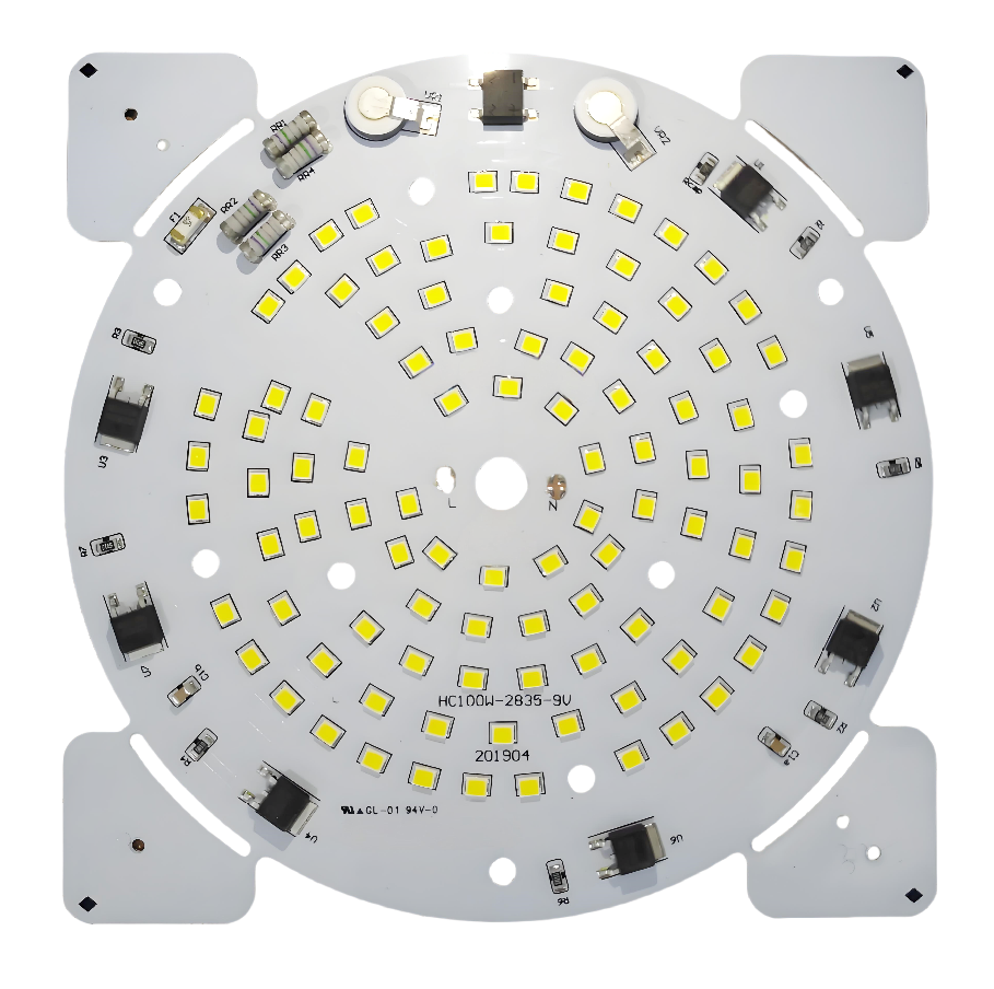
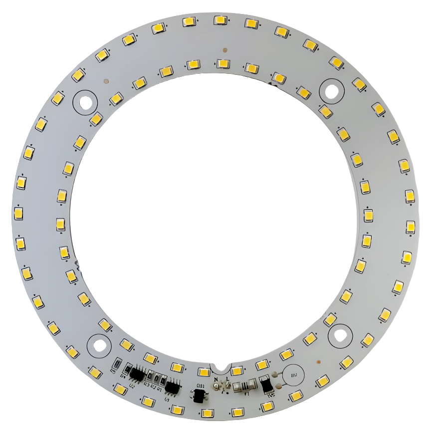
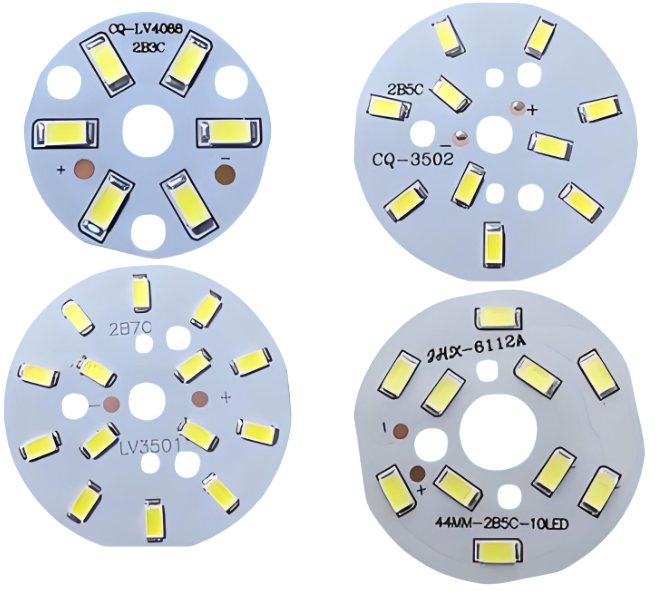
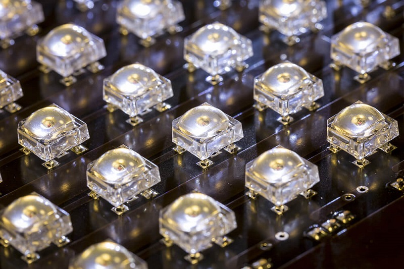
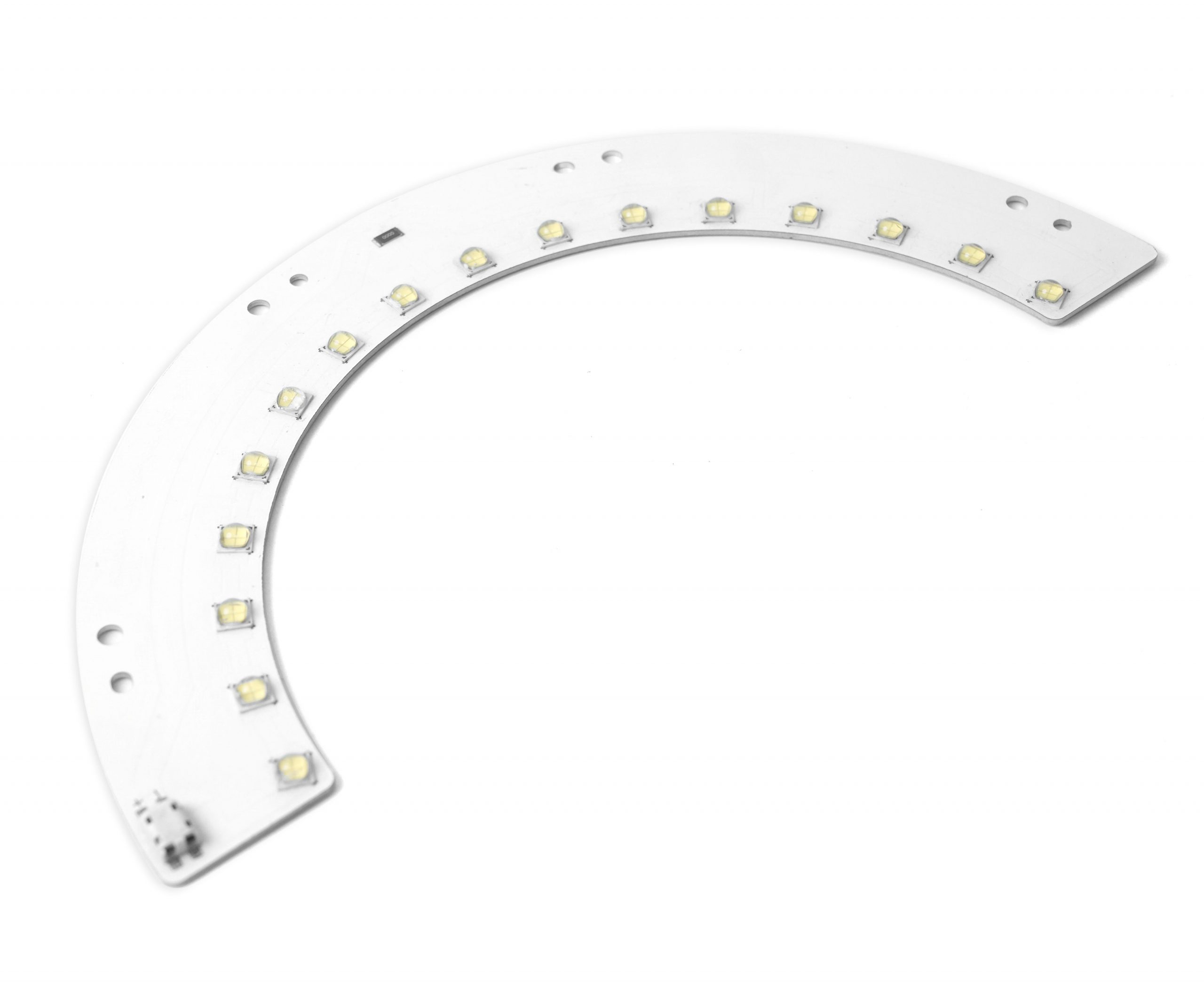
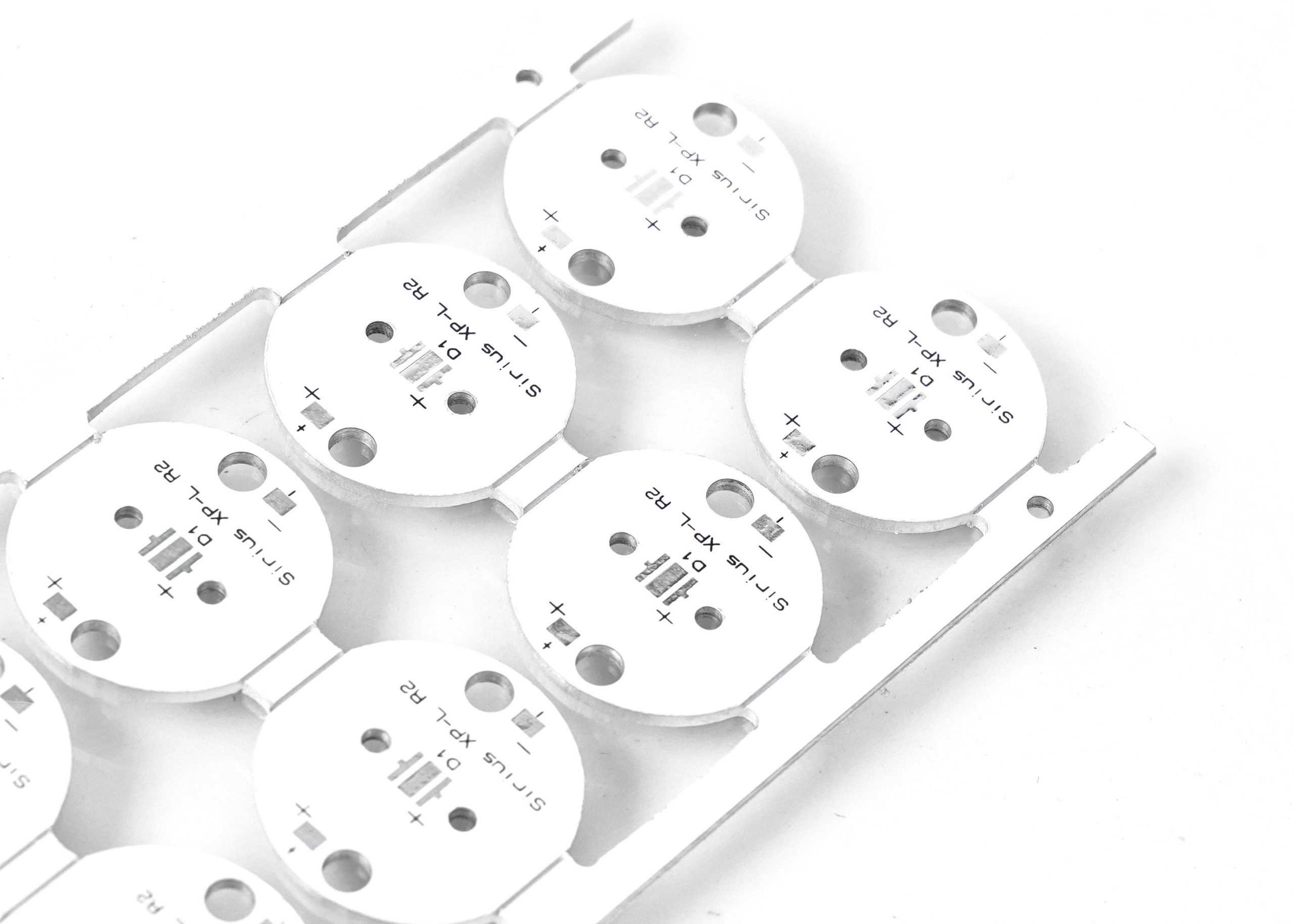
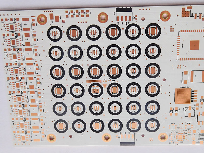
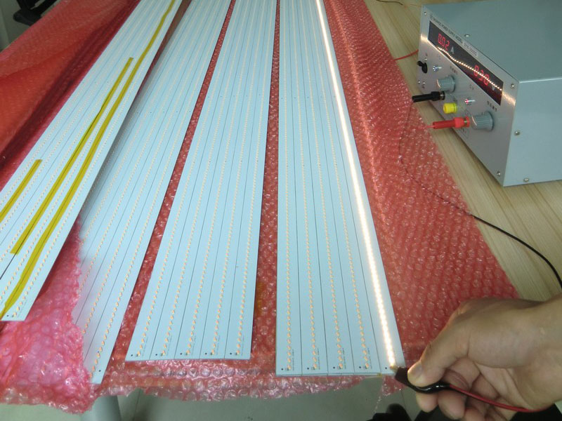
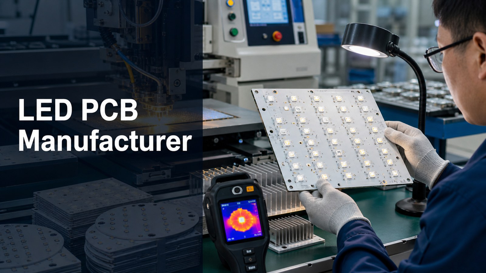
LED PCB manufacturer inspecting high power LED metal core circuit boards

An LED PCB manufacturer should help buyers control heat, assembly risk, material choice and RFQ assumptions before the board moves into prototype or production. For LED lighting and power electronics, the board is not only a carrier for components. It is part of the thermal path, mechanical mounting system and quality-control plan.

EBest Circuit supports LED PCB and MCPCB projects where buyers need DFM review, metal-core material confirmation, PCB fabrication, PCBA support, component sourcing and clear quote communication. A useful quote should review the LED package, current, substrate, copper, dielectric, heat sink interface, assembly files, test expectations and production quantity together.

Are heat, assembly and mounting risks clear before you approve the LED PCB quote?

Many LED PCB problems become visible only after samples are powered, mounted or exposed to real operating conditions. A low board price is not useful if the thermal path, LED orientation or mounting surface was never reviewed.

  • The quote does not confirm whether FR-4, aluminum core, copper core, ceramic or a direct thermal path structure fits the heat load.
  • The LED package and solder pad design are reviewed separately from the housing, heat sink or thermal interface material.
  • The BOM and CPL are sent late, so LED polarity, driver parts, connector direction and test points are not checked before assembly.
  • The board outline looks simple, but mounting holes, flatness, dielectric choice and surface finish create production or installation risk.
  • The buyer compares prices without knowing which inspection, illumination check, electrical test or thermal check is included.

EBest Circuit reviews LED PCB projects as heat-control and assembly projects, not only as bare boards.

  • We review Gerber or ODB++ files, stackup, substrate notes, copper, finish, outline, LED package, BOM, CPL and quantity together.
  • We check whether the heat path from LED package to board, metal core, thermal interface and housing is clearly defined.
  • We help buyers identify missing RFQ details such as power level, mounting method, test requirements, polarity notes and target production stage.
  • We can connect LED PCB fabrication with PCBA support, component sourcing, inspection and production planning.
  • We keep material and process claims tied to project review, so special thermal structures are not treated as generic standard boards.

How Should Buyers Choose an LED PCB Manufacturer?

A buyer should choose an LED PCB manufacturer by checking thermal review, substrate options, assembly support, inspection scope, cost assumptions and RFQ communication.

For LED projects, a supplier that only quotes from Gerber files may miss the conditions that decide product reliability. The LED package, current, board material, copper, dielectric layer, heat sink interface, mounting pressure and enclosure design all affect how the finished board behaves.

The strongest supplier fit is not always the nearest or the lowest line item. It is the supplier that can review board construction, assembly data and production risk before tooling or mass production starts.

LED PCB Manufacturing Capabilities Buyers Should Confirm

LED PCB buyers should confirm metal-core material, layer count, board thickness, copper weight, thermal conductivity, trace/space, hole size and surface finish before approving a manufacturer.

Capability Area What to Confirm EBest Circuit Evidence Basis
Base material Aluminum, copper, stainless steel or another project-specific route MCPCB capability sheet lists Aluminum / Copper / Stainless steel
Thermal conductivity Dielectric thermal class and heat path expectation Sheet lists 1 W / 1.5 W / 2.0 W / 3.0 W entries
Layer count Simple metal-core board or multilayer MCPCB structure Sheet lists 1-10 layers
Board thickness Mechanical fit and mounting requirement Sheet lists 0.6 mm minimum and 4.0 mm maximum board thickness
Copper and routing Current path, trace width and heat spreading Sheet lists 0.5 oz-10 oz conductor thickness and 4/4 mil line/space
Finish Solderability, storage and assembly process Sheet lists ENIG, ENEPIG, OSP and HASL (LF)

These values are useful screening points, not a replacement for file review. The final quote should still check the drawing, LED package, assembly method, acceptance criteria and quantity.

LED PCB Thermal Path: What the Board Must Move Away From the LED

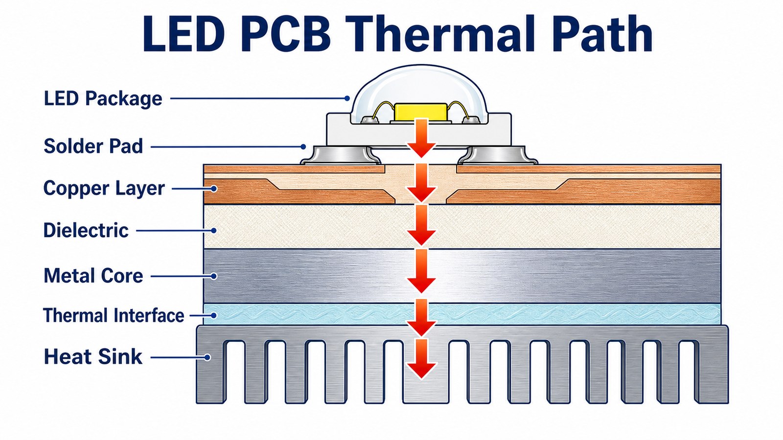
The thermal path should move heat from the LED package through the solder pad, copper, dielectric, metal core, thermal interface and heat sink or housing.

LED PCB thermal path from LED package through solder pad copper dielectric metal core and heat sink

In a high-power LED board, heat does not disappear inside the PCB. It must be guided toward a larger heat-spreading or heat-dissipating structure. If any part of the path is weak, the LED may still light during a sample test but lose brightness stability, solder reliability or service life under real load.

That is why LED PCB quotation should ask for more than outline, copper and quantity. The buyer should share LED power, expected mounting method, heat sink contact, operating environment, test conditions and whether the board is part of a lighting fixture, driver module or power electronics assembly.

MCPCB Materials: Aluminum, Copper and Stainless Steel Options

MCPCB material choice should follow heat load, mechanical support, weight, cost target and production method.

Aluminum core is often considered for LED lighting because it can provide a practical balance of heat spreading, weight and cost. Copper core can be considered when the design needs stronger heat spreading or current handling, but the quote must reflect material and process requirements. Stainless steel may be relevant for specific mechanical or environmental needs, but it should not be assumed without project review.

EBest Circuit’s checked MCPCB capability sheet lists aluminum, copper and stainless steel base material options. The right choice still depends on the LED package, board size, thermal target, mechanical installation and quantity.

FR-4, Metal Core, Ceramic or Direct Thermal Path: Which Route Fits?

The correct LED PCB route depends on heat density, electrical isolation, mounting, cost and product reliability requirements.

FR-4 can be suitable for low-power indicators, control sections or LED boards where heat density is modest and the system has enough margin. Metal core PCB is often considered when the board must spread heat away from LEDs more effectively. Ceramic PCB or direct thermal path structures may be evaluated for more demanding thermal designs, compact modules or high-power applications.

EBest Circuit has relevant internal-link paths for metal core PCB, direct thermal path board structures and ceramic PCB. The article does not claim one route is always best because the final choice depends on project files and operating conditions.

Copper Weight, Dielectric, Board Thickness and Surface Finish Choices

Copper weight, dielectric performance, board thickness and surface finish affect both thermal behavior and manufacturability.

Higher copper can support current and heat spreading, but it also changes etching, spacing and cost. Dielectric selection affects heat transfer and electrical isolation. Board thickness affects mechanical mounting, flatness and compatibility with the final housing. Surface finish affects solderability, storage and assembly planning.

The checked MCPCB sheet lists conductor thickness from 0.5 oz to 10 oz, board thickness from 0.6 mm to 4.0 mm, and surface treatments including ENIG, ENEPIG, OSP and HASL (LF). These should be treated as quote-review ranges because the final build depends on the drawing, stackup and process route.

LED Package, Polarity, Driver and Connector Assembly Checks

LED PCB assembly should verify LED polarity, package orientation, driver components, connectors, soldering access and test points before production.

A bare LED board can be fabricated correctly and still fail as an assembled product if LED polarity is unclear, the CPL is wrong, driver components are substituted without review, or connectors face the wrong direction. For PCBA work, the manufacturer should review Gerber, BOM, CPL and assembly drawings as one package.

For projects that need assembly, EBest Circuit can connect PCB fabrication with PCBA and PCB assembly support and component sourcing. That is important when LED binning, driver availability, approved alternates or connector lead time affects the final build.

DFM Review for LED PCB Manufacturing

DFM review should check whether the LED board can be fabricated, assembled, mounted, inspected and tested without avoidable risk.

Useful DFM checks include LED pad design, solder mask clearance, copper balance, thermal pad geometry, mounting holes, panelization, board outline, fiducials, silkscreen polarity marks, connector location, heat sink interface and test point access. If the board is metal core, the review should also consider mechanical processing and isolation requirements.

Buyers should treat DFM as part of supplier selection. A fast quote that ignores heat path and assembly data can become expensive after sample failure, fixture changes, rework or delayed production approval.

Testing and Inspection for LED PCB Projects

LED PCB testing should confirm electrical function, assembly correctness, visual quality and project-specific thermal or illumination requirements.

Common checks can include visual inspection, AOI, polarity checks, continuity, electrical test, solder joint review, connector inspection, sample illumination check and functional verification. For higher-risk products, the buyer may also define thermal test conditions, aging expectations or fixture-based tests.

Do not assume all LED PCB manufacturers include the same test scope in the base quote. If the project needs illumination, burn-in, thermal observation or functional testing, write those requirements into the RFQ.

What Drives LED PCB Manufacturing Cost?

LED PCB manufacturing cost is mainly driven by substrate, copper, dielectric, layer count, board size, assembly scope, testing, quantity and special thermal requirements.

Cost Factor Why It Changes the Quote Buyer Action
Substrate FR-4, aluminum, copper, ceramic and special thermal structures use different material and process routes State the preferred route or ask for engineering review
Thermal target Heat path requirements can affect dielectric, copper, metal base and inspection scope Share LED power, mounting and operating conditions
Assembly LEDs, drivers, connectors, sourcing and testing add process scope Send BOM, CPL and assembly drawings with the RFQ
Finish and copper Surface finish and copper weight affect fabrication and soldering Confirm finish preference and current requirements early
Quantity and stage Prototype, pilot and production orders have different setup and validation needs Give both first-build and repeat-order expectations

The lowest quoted board price is not always the lowest project cost. If a quote excludes assembly, LED sourcing, test requirements or thermal review, the missing scope can reappear later as delay or rework.

Prototype, Pilot and Production Planning for LED Boards

LED PCB prototypes should be planned so the same design can move toward pilot and production without rebuilding the supplier assumptions from zero.

A prototype often proves fit, brightness, current path and early thermal behavior. A pilot build checks repeatability, assembly flow, test method, packaging and production handling. A production run needs stable material sourcing, inspection records, approved alternates and a clear quality plan.

Tell the manufacturer whether the order is only a one-time prototype or the first step toward repeat production. That helps the supplier review panelization, material availability, test scope and cost assumptions more realistically.

Supplier Evaluation Checklist for LED PCB Buyers

A strong LED PCB supplier should ask about thermal path, material route, assembly files, testing and production stage before final quote approval.

  • Can the supplier explain whether FR-4, MCPCB, ceramic or a direct thermal path board fits the heat load?
  • Can they review LED package data, power level, current path, mounting and heat sink interface?
  • Can they support metal-core fabrication and PCBA when the project needs assembly?
  • Can they check BOM, CPL, LED polarity, driver parts, connectors and test requirements?
  • Can they separate standard capability from project-dependent thermal structures?
  • Can they give a quote that states assumptions instead of hiding missing scope?
  • Can they support prototype, pilot and production planning without forcing the same process on every order?

RFQ File Checklist for LED PCB Manufacturing

A complete LED PCB RFQ should include fabrication files, LED and thermal requirements, assembly data, testing scope, quantity and target schedule.

  • Gerber or ODB++ files, drill files and board outline.
  • Stackup notes, substrate preference, copper weight, board thickness and surface finish.
  • LED package, power/current information, heat path notes and mounting method.
  • Mechanical drawing, heat sink interface, mounting holes and enclosure constraints if available.
  • BOM, CPL, assembly drawing, LED polarity notes, driver details and connector direction.
  • Inspection, illumination, electrical, functional or thermal test requirements.
  • Prototype quantity, pilot quantity, production forecast and target schedule.

If some details are still open, mark them clearly. A good manufacturer can help review open questions, but it cannot safely quote assumptions that are never stated.

FAQ About LED PCB Manufacturers

What is an LED PCB manufacturer?

An LED PCB manufacturer builds printed circuit boards used for LED lighting, display, driver and power electronics projects. A strong supplier reviews thermal path, substrate, copper, assembly, testing and RFQ files, not only bare board fabrication.

What type of PCB is best for LED lighting?

The best type depends on heat load, current, mounting and cost. FR-4 can fit low-power LED boards, while aluminum core, copper core, ceramic or direct thermal path structures may be considered when heat density is higher.

What files are needed for an LED PCB quote?

Send Gerber or ODB++ files, drill files, stackup, material notes, LED package information, BOM, CPL, assembly drawing, quantity, surface finish and testing requirements. Heat sink or mounting information is useful for thermal review.

Can EBest Circuit support LED PCB assembly?

Yes. EBest Circuit can review LED PCB fabrication together with BOM, CPL, component sourcing, assembly drawings, inspection and testing requirements when the project needs PCBA support.

Why do LED PCB quotes vary so much?

Quotes vary because substrate, copper, dielectric, board size, finish, assembly, test scope, quantity and thermal requirements can all change the real work. A useful comparison must include the same RFQ files and assumptions.

Send Your LED PCB RFQ

If you need an LED PCB manufacturer for prototype, pilot or production work, send your Gerber or ODB++ files, stackup, LED package details, power/current notes, BOM, CPL, assembly drawing, quantity, material preference, surface finish, test requirements and target schedule to sales@bestpcbs.com. EBest Circuit will review the heat path, MCPCB options, fabrication details, assembly scope and quote assumptions before your project moves into production.

You may also like

LED PCB Manufacturer for Lighting and Power Electronics
Wednesday, July 15th, 2026
LED PCB manufacturer thermal inspection

An LED PCB manufacturer builds circuit boards that carry LEDs, manage heat, support reliable solder joints, and fit the mechanical and optical design of the final lighting product. For buyers, the main decision is not simply whether a supplier can make a PCB. The decision is whether the supplier can review thermal needs, substrate choice, copper design, LED placement, driver connections, assembly risk, testing, and RFQ files before production starts.

This guide is written for lighting engineers, purchasing teams, and product developers comparing LED PCB manufacturers for prototypes, pilot builds, and production. It focuses on commercial sourcing decisions: material, heat path, assembly, quality control, cost, and the files needed for a useful quote.

LED PCB Manufacturer Selection at a Glance

A good LED PCB manufacturer should help match board material, heat dissipation path, LED placement, assembly method, and inspection scope to the lighting application. LED boards are often more thermally sensitive than ordinary signal boards because light output, color stability, solder joint life, and product safety can all be affected by heat.

Buyer decision What to confirm Why it matters
Substrate FR-4, aluminum, copper, ceramic, or direct thermal path design Controls heat transfer, cost, weight, and manufacturability
Thermal path LED pad design, dielectric, copper, metal core, heat sink interface Affects LED life, brightness stability, and field reliability
Assembly LED package, polarity, driver parts, connectors, soldering method Reduces placement errors and solder defects
Testing Visual, AOI, polarity, illumination, electrical and thermal checks Finds issues before boards reach final products

When You Need an LED PCB Manufacturer Instead of a General PCB Supplier

You need an LED PCB manufacturer when heat, brightness, LED placement, mechanical fit, or assembly reliability are central to the project. A general PCB supplier may fabricate a board correctly from Gerber files, but LED products often need deeper review of heat path, component polarity, substrate choice, and how the board will be mounted into a fixture or power module.

Projects such as high-power lighting, automotive lighting modules, signage, industrial lamps, grow lights, UV LED systems, and compact consumer lighting need a supplier that can read the PCB files together with the LED package data, driver circuit, housing constraints, and expected operating conditions.

LED PCB Materials: FR-4, Aluminum, Copper, Ceramic and DTP Options

LED PCB material selection should follow the thermal and mechanical requirements of the product, not only the lowest board price. FR-4 may be acceptable for low-power indicator boards or lower thermal stress designs. Metal core PCB, copper core PCB, ceramic PCB, or direct thermal path structures may be considered when heat density is higher.

Bestpcbs has relevant product references for metal core PCB, SinkPAD-style thermal paths, ceramic PCB, and PCBA service. Exact material limits and construction options should be confirmed from the project files and capability tables before quoting. The safe RFQ approach is to share LED power, board outline, mounting surface, target temperature conditions, and thermal interface expectations early.

Thermal Design Questions to Answer Before RFQ

Thermal design questions should be answered before quote approval because heat problems are expensive to fix after LED placement and fixture design are locked. Even a well-fabricated board can fail if the heat path from LED junction to board, heat sink, housing, and ambient environment is not considered.

  • What is the LED package and power level?
  • Is the board mounted to a heat sink, housing, or metal frame?
  • Does the design need aluminum, copper, ceramic, or direct thermal path construction?
  • Are there thermal vias, exposed pads, or special copper areas?
  • Will the buyer provide thermal simulation, test conditions, or acceptance criteria?

Copper, Dielectric, Board Thickness and Surface Finish Choices

Copper, dielectric, board thickness, and surface finish choices affect both thermal behavior and manufacturing cost. For LED products, board thickness may be tied to mechanical fit, copper may be tied to current and heat spreading, and surface finish may affect solderability and storage conditions.

Do not assume all LED boards require the same build. A decorative LED board, a high-current lighting module, a compact driver board, and a high-power thermal board may need different substrate and assembly planning. The RFQ should state current, LED density, operating environment, finish preference, board thickness target, and mounting constraints.

LED PCB Assembly: LEDs, Drivers, Connectors and Polarity

LED PCB assembly requires careful handling of LED polarity, package orientation, driver components, connectors, and heat-sensitive placement details. A correct bare board is not enough if the assembled board has rotated LEDs, weak solder joints, or inconsistent brightness caused by component or process issues.

For assembly projects, provide BOM, CPL, assembly drawing, polarity notes, LED binning requirements if any, connector direction, and test expectations. If component sourcing support is needed, the component sourcing service is relevant for BOM availability, approved alternates, and supply risk review.

DFM Review for LED PCB Manufacturing

DFM review for LED PCB manufacturing checks whether the board can be fabricated, assembled, inspected, and mounted without avoidable production risk. This review should happen before production, not after defects appear.

Typical checks include LED pad size, solder mask clearance, copper balance, thermal pad design, mechanical holes, panelization, board outline, silkscreen clarity, polarity marking, connector placement, heat sink interface, and test point access. If the board also needs assembly, the review should connect Gerber, BOM, CPL, and assembly drawing data.

Testing and Inspection for LED PCB Projects

LED PCB testing should match the actual product risk, including electrical function, polarity, solder quality, visual appearance, and thermal behavior where required. Not every project needs every test, but the buyer should define what must be checked before shipment.

Possible checks include bare-board electrical testing, AOI, visual inspection, polarity verification, lighting function, driver output, current draw, and project-specific thermal checks. For assembled boards, the PCBA service path is relevant because assembly quality and board quality must be controlled together.

What Drives LED PCB Manufacturing Cost?

LED PCB cost is driven by thermal structure, material, copper, surface finish, assembly complexity, component sourcing, testing, and quantity. A low-power FR-4 LED indicator board and a metal-core high-power lighting module should not be priced or evaluated the same way.

Cost factor Impact on quote
Substrate FR-4, aluminum, copper, ceramic, and DTP structures follow different process routes.
Thermal design Thermal vias, metal cores, copper areas, and heat sink interface can add review and processing needs.
LED package and quantity Package size, polarity, and density affect assembly time and inspection risk.
BOM sourcing LED bins, drivers, connectors, and approved alternates can change price and schedule.
Testing Lighting, electrical, programming, or thermal checks add process time.

For a broader pricing view, compare this LED-specific checklist with the custom PCB cost guide.

Prototype, Pilot and Production LED PCB Planning

LED PCB prototypes should validate thermal and assembly assumptions before the buyer commits to production tooling, BOM purchasing, or fixture integration. Early prototypes help find LED spacing, brightness, driver, connector, and heat path issues while the design can still be changed.

For pilot and production, confirm whether the BOM is stable, whether LED binning matters, whether test fixtures are needed, and whether the same board build can be repeated. For engineering-stage builds, the prototype PCB assembly page is a useful internal reference.

How to Compare LED PCB Manufacturers

Compare LED PCB manufacturers by their ability to review thermal design, material choice, assembly data, sourcing risk, and testing requirements, not only by the first quoted unit price. A supplier that ignores heat and polarity can look inexpensive until the first failed build.

  • Can the supplier discuss LED substrate options and thermal path decisions?
  • Can they review Gerber, BOM, CPL, assembly drawing, and test needs together?
  • Do they ask about LED power, mounting, heat sink, operating environment, and brightness requirements?
  • Can they support both PCB fabrication and LED PCB assembly if needed?
  • Do they explain cost drivers instead of giving only a flat price?

Common LED PCB Sourcing Risks

Common LED PCB sourcing risks include weak thermal assumptions, missing polarity notes, unclear LED binning, wrong substitutions, and incomplete test requirements. These risks are easier to prevent before production than to repair after boards are assembled.

  • Thermal mismatch: substrate or heat path does not match LED power and fixture design.
  • Polarity error: LED orientation is unclear in CPL or assembly drawings.
  • BOM ambiguity: LED bins, drivers, connectors, or alternates are not approved.
  • Mechanical conflict: board holes, outline, or heat sink interface do not fit the final product.
  • Testing gap: brightness, current, function, or temperature checks are not defined.

RFQ Checklist for LED PCB Manufacturing

An LED PCB RFQ should include board files, LED and driver details, thermal requirements, assembly data, quantity, and inspection expectations. The more specific the RFQ, the fewer assumptions the supplier must make.

  • Gerber or ODB++ files and drill data
  • Board material, thickness, copper, finish, and thermal path notes
  • LED package, power, density, binning or brightness requirements if applicable
  • BOM with manufacturer part numbers and approved alternates
  • CPL / pick-and-place file and assembly drawing
  • Mounting, heat sink, housing, or mechanical constraints
  • Quantity for prototype, pilot, and production
  • Electrical, lighting, polarity, functional, or thermal test requirements

Frequently Asked Questions

What is an LED PCB?

An LED PCB is a printed circuit board designed to mount LEDs and related components while supporting electrical connection, heat transfer, mechanical fit, and product reliability. The board may use FR-4, metal core, ceramic, or other construction depending on power and thermal needs.

Is aluminum PCB always required for LED lighting?

No. Aluminum PCB is common for many lighting applications, but not every LED board requires it. Low-power designs may use FR-4, while higher heat-density designs may need aluminum, copper, ceramic, or direct thermal path structures.

Can one supplier handle LED PCB fabrication and assembly?

Yes, if the supplier can review the bare-board files, BOM, CPL, LED polarity, assembly drawing, and testing requirements together. This is often useful when the project has thermal and assembly risks.

What files are needed for an LED PCB quote?

Send Gerber or ODB++ files, drill files, material and thermal notes, BOM, CPL, assembly drawing, quantity, test requirements, and any mechanical or heat sink constraints.

What causes LED PCB quote differences between suppliers?

Quotes can differ because suppliers make different assumptions about substrate, copper, surface finish, LED package, component sourcing, assembly method, inspection, test scope, and production quantity.

Send an LED PCB Manufacturing RFQ

If you need LED PCB manufacturing or LED PCB assembly support, send your Gerber or ODB++ files, BOM, CPL, LED package details, quantity, material notes, thermal requirements, surface finish, testing requirements, and target delivery plan to the Best Technology / bestpcbs engineering team at sales@bestpcbs.com. The team can review the project for board build, heat path, sourcing, assembly, inspection, and quote preparation before production starts.
You may also like

LED PCB Design, LED Circuit Board Design, PCB Design Services
Tuesday, April 1st, 2025

What is LED PCB?

Just as its name implies, LED PCBs are specialized circuit boards designed to power and support LED (Light Emitting Diode) lights. These PCBs must manage heat efficiently and distribute power effectively to handle the electrical load and heat generated by LEDs. They provide the essential platform for mounting LEDs and connecting them to other electronic components. LED PCBs are used in a wide variety of applications, ranging from basic light fixtures to sophisticated lighting systems in automotive, signage, and consumer electronics.

Typically, LED PCBs are made from materials with high thermal conductivity, such as aluminum or copper, to effectively manage heat. The design of these boards varies depending on the type of LED chips, such as surface-mount (SMD) LED or through-hole. LED PCBs also come in various forms, including flexible, rigid, and semi-flexible options, each tailored to specific lighting applications. Regardless of the type, careful attention to the LED PCB design is essential to achieve optimal performance and efficiency.

LED PCB Design Basics

Actually, the basics of a LED PCB design is a deep understanding and practice of both electrical and thermal engineering principles. LED circuit boards differ from standard PCBs because they must support higher currents and dissipate more heat. Therefore, careful planning is required in selecting materials, components, and layout strategies to ensure long-term reliability and efficiency.

At its core, LED PCB design focuses on three main factors:

  • Thermal Management: LED devices generate heat, which can damage the components if not managed correctly.
  • Current Distribution: The PCB must handle the specific current requirements of each LED.
  • Power Design: Since LEDs operate at specific voltages and currents, the power supply must be designed to match these needs.

5 Commonly Used LED PCB Design Software

Before starting a LED PCB design, let’s know the commonly used software during the design process. These tools can help to handle complex circuits, including component placement, routing, and thermal management. It can save much time and money for us.

LED PCB Design

1. Altium Designer

Altium is a powerful tool known for its user-friendly interface and extensive design features. It offers comprehensive options for both schematic capture and PCB layout, it is a popular choice for professional LED PCB design.

2. Eagle

For smaller business and hobbyists, Eagle is a good choice because it offers an easy-to-use interface and a solid set of features to creating LED circuit boards without steep learning curves.

3. KiCad

KiCad is an open-source and free PCB design tool that is well-regarded for its flexibility and cost-effectiveness. It’s suitable for users who need a more customizable design solution.

4. Mentor Graphics PADS

PADS is well-suited for complex and high-performance PCB designs, particularly for high-frequency LED applications that demand precision and accuracy.

5. DipTrace

DipTrace offers a combination of schematic capture and PCB layout in a user-friendly environment. Its drag-and-drop interface helps reduce design time.

How to Design a LED Circuit Board? – Step by Step

A good LED circuit board is based on a good LED PCB design. When you have a clear ideal and thought about your LED PCB, then you can start designing your PCB. Same as normal FR4 PCB, the LED PCB design starts from schematic drawing – layout – trace wiring – power integrity checking.

1. LED PCB Schematic Diagram Design

This diagram serves as the foundation for the PCB design, so any errors at this stage can lead to problems in the final board. Using a reliable schematic diagram tool to draw your circuit accurately and efficiently. Additionally, avoid overly complex circuits with multiple connections in a single diagram. Keeping the schematic clear and simple will make troubleshooting easier and ensure the design process progresses without issues.

LED PCB Design

2. LED PCB Layout

Once the schematic is finalized, the next step is the PCB layout. This involves placing the components and routing the traces that will carry the electrical signals to power the LEDs. This stage directly impacts the PCB’s performance, so precise planning and routing are essential. During the pcb layout, remember these tips:

  • High-power LEDs should be placed in areas with good airflow or close to heat sinks. It’s also important to keep resistors and power supply components away from heat-sensitive parts.
  • To ensure that the traces can handle the required current without overheating, you need to calculate the trace width. Tools like IPC-2221 or use our Online PCB Trace Width Calculators can help determine the appropriate width based on the current and copper thickness used in the PCB. For example, a 1oz copper PCB might need a trace width of 2mm to carry a 2A current safely.
  • Using separate power and ground planes to avoid voltage drops and noise. Power planes provide a low-resistance path for high-current traces, while ground planes help with signal integrity and reduce noise.
  • Thermal vias are often used to transfer heat from the LED to the PCB’s back layers or heat sinks. For high-power LEDs, these vias must be carefully placed to ensure that heat is efficiently dissipated.

3. LED PCB Wiring

Wiring refers to the creation of the electrical traces that connect the components on the PCB. Compared with FR4 PCB, wiring an LED circuit board is generally straightforward, but attention to detail is essential, particularly when it comes to the lead lengths of each component in the LED PCB design. Typically, the cathode lead is the shortest and connects to the same socket as the anode. Similarly, the resistor should be connected to the anode’s socket, and the other wire, often red or black, should follow the same principle.

Here are some important LED PCB design guidelines for wiring the LED circuit board:

  • Component Selection: Before starting the design, choose the LED components based on the specific requirements of your LED circuit board.
  • Plan the Wiring Layout: Carefully plan your LED PCB wiring layout and double-check its accuracy before proceeding with the wiring process.
  • Via and Trace Optimization: Minimize the use of vias, as they can introduce resistance and inductance. If vias are necessary, ensure they are appropriately sized and placed to handle the current.
  • Proper Grounding: Ensure that all LED components in the PCB design are correctly grounded to the circuit board.
  • Wire Gauge Selection: Use the appropriate wire gauge for each section of the LED PCB, depending on the current load in each path.
  • Prevent Interference: If any wire leads cross over other conductive paths, clamp them securely to prevent interference or accidental contact with other components.
  • Heat Shrinking: Apply heat shrink tubing to exposed wire junctions to protect against interference and reduce the risk of short circuits.
  • Signal Routing: Ensure that signal traces (such as PWM signals in RGB LED designs) are routed separately from power traces to prevent interference and maintain signal integrity.
  • Continuity Check: Before powering up your LED PCB, check for continuity throughout the circuit to ensure everything is connected properly.
  • Power Source: Always use an approved power supply when connecting external voltage to the LED PCB.
  • Final Check: Before applying power, make sure there are no short circuits, open circuits, reverse polarity issues, or incorrect component placements.
  • Test the LEDs: Regularly test the LEDs to ensure optimal performance under various operating conditions.

4. LED PCB Power Design and Analyzing

LED PCBs often require specific power designs to prevent overloading and ensure efficient energy consumption. You must consider the input voltage and how power will be distributed across the board. Proper power analysis ensures that the PCB operates within its designed power specifications.

5. LED PCB Signal Integrity Analysis

Signal integrity is an essential aspect of LED PCB design, particularly for high-speed or high-frequency LED applications. Ensuring that signals are not distorted during transmission will improve the overall performance and efficiency of the LED circuit. This phase involves simulating the behavior of the circuit to ensure it performs optimally under various conditions.

  • Simulate circuit behavior: Use specialized tools to simulate how the circuit will behave under different loads and environmental conditions.
  • Ensure minimal noise: Check for potential interference or noise in the circuit that could affect LED performance.

If you are interested in our LED metal core PCB manufacturing process, then the below video will show you all the steps in detailed.

LED Circuit Board Design Considerations

When designing an LED circuit board, several factors must be considered to optimize performance and reliability:

1. Outline Shape

LED PCBs come in various shapes, such as round, rectangular, or custom forms, depending on the final application. For example, LED strip PCBs are often flexible and come in long, narrow shapes, while LED array PCBs may need to accommodate multiple LEDs in a compact rectangular form.

2. Thermal Management

Effective thermal management is one of the most critical considerations when designing an LED PCB. LEDs generate heat during operation, and without proper heat dissipation, performance can degrade quickly, leading to shorter lifespan and possible failure. Aluminum PCBs are often used in LED designs due to their excellent thermal conductivity. Alternatively, copper-clad PCBs may be chosen for high-power applications to ensure that heat is efficiently transferred away from the LEDs.

3. Current Control

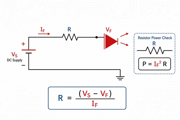
Each LED needs a current-limiting resistor to avoid excessive current that could damage the LED. In high-power LED applications, constant current drivers are often used to regulate the current supply.

4. Component Placement

Components should be arranged to minimize heat buildup, reduce interference, and maintain a clean signal path.

  • LED Positioning: Place high-power LEDs in areas with better airflow or near heat sinks. Ensuring adequate space around each LED can help manage heat more effectively.
  • Resistor and Capacitor Placement: Resistors and capacitors should be placed near the LEDs to minimize the impact of parasitic inductance or resistance. Proper placement also improves the overall efficiency of the circuit and minimizes signal loss.

5. Layout Optimization

The layout takes into account signal integrity and power integrity. In the layout, you need to follow the following principles:

  • Power and signal lines should be as wide as possible to reduce resistance and inductance.
  • The length of the power and signal lines should be as short as possible to reduce signal delay and noise.
  • Sensitive signal lines should be kept away from noise sources, such as motors, switches, etc.
  • The arrangement of power and signal lines should take into account the issue of electromagnetic interference (EMI).

LED PCB Design Success Cases at EBest Circuit (Best Technology)

EBest Circuit (Best Technology) is a leading LED PCB manufacturer in Shenzhen China, a city famous of its well-developed electronics industry. Since established in 2006, we have rich experiences in metal core PCB manufacturing, including every aluminum LED PCB and copper core LED PCBs. Different with FR4 PCB, the key manufacturing difficulty of LED PCB is its lamination between dielectric and base, we deeply know its importance, so we set a separate lamination department with experience operators to solve this problem. Additionally, our factory equipped with advanced manufacturing machines to improve our capacity and efficiency. With strong R&D team, we are able to offer better LED PCB design solution to our customers, ensure one-time prototype success. Below, we highlight several success cases that demonstrate how we served our customers.

LED PCB Design, LED Circuit Board Design, PCB Design Services

1. High-Power LED PCB Design for Street Lighting

Customer Challenge:

One of our clients, a leading provider of outdoor lighting solutions, approached us with a high-power LED streetlight project. The primary difficulty they faced was heat dissipation. LED streetlights generate a significant amount of heat, and without effective thermal management, the lifespan of the LEDs would dramatically decrease, leading to frequent failures and increased maintenance costs. The client needed a robust and reliable LED PCB design that could handle the heat produced by high-power LEDs while ensuring energy efficiency and long operational life.

Our Solution:

We suggested aluminum-based PCBs since it has better thermal conductivity than FR4 PCB. To improve heat dissipation further, we added thermal vias and designed the layout to maximize the heat transfer from the LEDs to the surface. In this way, heat sinks can be removed to save some spaces and costs. Additionally, we incorporated constant-current drivers to maintain a stable power supply and prevent current surges that could further exacerbate the heating issue.

Outcome:

Our high-power LED PCB design successfully met the client’s stringent requirements. The energy-efficient design led to reduced operational costs, and the improved thermal management extended the lifespan of the streetlights.

2. RGB LED PCB Design for Swimming Pool

Customer Challenge:

A client in the entertainment industry required a RGB LED PCB for dynamic visual displays in a large-scale concert venue. The biggest challenge was ensuring color accuracy, brightness consistency, and signal integrity across a large array of LEDs. Given the complexity of RGB mixing, the client needed a design that would maintain color uniformity and prevent color distortion or flickering, especially during high-speed color transitions.

Our Solution:

We tackled the signal integrity problem by carefully routing the RGB signal traces to minimize interference and crosstalk. We also integrated pulse-width modulation (PWM) to control brightness, allowing for smooth color transitions and fine-tuned brightness control. The PCB layout included dedicated ground planes to prevent noise from power traces and ensured that the voltage regulators could handle the high current demands without introducing voltage fluctuations that could impact color performance.

Outcome:

The final design ensured vibrant, accurate colors and consistent brightness, even across large areas of the display. The client was able to achieve visually stunning, seamless light transitions for dynamic effects, greatly enhancing the overall viewing experience.

3. SMD LED PCB Design for Compact Devices

Customer Challenge:

A customer in the consumer electronics industry needed an SMD LED PCB for a handheld device. The main challenge here was to design a compact PCB that could handle the power requirements of high-brightness LEDs without compromising the device’s sleek profile. Additionally, the customer faced the issue of heat buildup in such a confined space, which could negatively affect both performance and lifespan.

Our Solution:

To accommodate the client’s space constraints, we employed fine-pitch SMD LEDs and used multi-layer PCB technology to stack components vertically. This allowed us to maximize the use of the available space while maintaining efficient current flow and power distribution. For heat dissipation, we incorporated thermal vias and copper planes to spread heat away from the LEDs. Our design also included current-limiting resistors and voltage regulators to stabilize the power supply to each LED, ensuring consistent performance despite the small size of the PCB.

Outcome:

The customer was extremely satisfied with the reliable, long-lasting solution, which became a cornerstone feature of their product line.

4. Simple LED PCB Design for Residential Lighting

Customer Challenge:

A client in the home lighting industry required a simple LED PCB for mass production of affordable, energy-efficient residential lighting solutions. The challenge was to design a PCB that was both cost-effective and reliable, while ensuring that the LEDs would not overheat or burn out prematurely, especially in long-duration use cases.

Our Solution:

For this project, we designed a single-layer PCB to minimize costs while maintaining functionality. We incorporated current-limiting resistors to protect the LEDs and used low-cost components that could be easily sourced for mass production. Thermal considerations were addressed by optimizing the component placement and providing ample space around the LEDs for heat dissipation. We also ensured the design could handle voltage fluctuations by incorporating a voltage regulator.

Outcome:

The design resulted in a highly affordable, yet durable LED PCB that was well-suited for high-volume production.

5. Flexible LED Strip PCB Design for Custom Installations

Customer Challenge:

A client involved in decorative lighting for both residential and commercial spaces required a flexible LED strip PCB that could be easily bent and shaped around various installations. The major hurdle was ensuring consistent power distribution along the strip while maintaining a compact and flexible design. The client also needed the strips to withstand outdoor conditions without compromising on performance.

Our Solution:

We designed the flexible LED PCB using polyimide film for its excellent flexibility and durability. To ensure uniform brightness across the entire length of the strip, we used constant voltage circuits and low-resistance traces to minimize power loss. We also applied encapsulation to protect the PCB from environmental factors such as moisture, UV rays, and physical wear and tear.

Outcome:

The resulting LED strip was not only flexible but also highly durable and weather-resistant, making it suitable for both indoor and outdoor use. The customer was able to offer a customizable, high-quality lighting solution that could be used in a wide range of applications, from commercial signage to home decor.

FAQs

Q1: Are the via’s important for the thermal conduction?

From the via’s perspective, the via can be helpful in thermal conduction. At the same time, it is not that more heat dissipation through holes is better. The design of Via needs to be followed the minimax distance between holes. From the metal core material, the copper material is better than aluminum core in same situation. And sinkpad copper core PCB is better than copper core PCB. Because the convexity pad will be helpful in thermal conductivity. From the dielectric film, the 3W material is best. 2W material is better than 1W material. From the design of metal core PCB, the larger the area of solder mask opening means the larger the exposed copper surface outside, and the better the heat dissipation effect.

Q2: Does the dielectric in MCPCB cause problems at high temperatures?

The dielectric in MCPCB will cause problems at high temperatures, and the dielectric layer of MCPCB is the bottleneck of high temperature, because the Tg value of the layer is only 130℃.

Q3: What is the thickness of the thermal conductivity?

0.8W/m.k,Thickness=50-75um

1.0W/m.k,Thickness=75-100um;

1.5W/m.k,Thickness=100um

2.0W/m.k,Thickness=100-125um;

3.0W/m.k,Thickness=125-200um

For the breakdown, it is bigger when the line space is wider and the dielectric layer is thicker. Normally, the copper thickness is 10Z and 2OZ and surface finishing is HASL(LF), ENIG and OSP.

Q4: Can the aluminum be made as the base of sinkpad MCPCB?

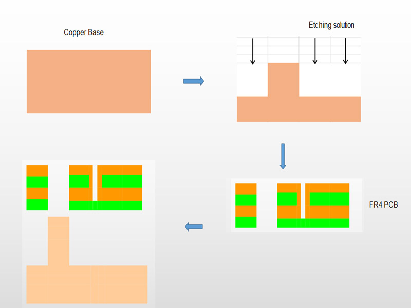
Actually, the sinkpad can only use copper as the base. Because the SinkPad will etch the copper base into convex platform with Copper Etching Solution, then hollow out the Double Layer FR4 PCB, and do lamination with the convex platform. However, regarding of current technical conditions, since aluminum or aluminum alloy cannot directly react with acid, the reaction process is too complex and difficult to control, which will increase the difficulty of etching the LED pad platform. Considering the scrap rate, the process of etching LED pad platform with aluminum is more complex and the overall cost is higher.

Q5: It is possible dielectric + top metal layer to be >500um for wire bonding?

The dielectric layer and metal layer don’t affect the wire bonding, it depend on ENEPIG thickness, we do a lot of this kind of boards for our customers, as long as the do it with 3u”, then it is very good for wire bonding. If you insist on needing dielectric + top metal layer to be >500um, then the copper thickness need to be 10 OZ(350um), the price will be very high.

You may also like

OEM ODM HASL Lead Free 94V0 LED PCB, Quick Turn Prototype
Tuesday, April 1st, 2025

What is HASL Lead Free 94V0 LED PCB?

A HASL lead free 94V-0 LED PCB is a printed circuit board that designed for LED lightings, while coating with HASL lead free surface treatment and meet the 94V-0 flame retardant standard. HASL, full name is Hot Air Solder Leveling, it is a cost-effective surface finish used in the PCB manufacturing process. In the HASL lead-free process, the traditional lead-based soldering is replaced with a lead-free solder material, which is in line with environmental regulations like RoHS.

The 94V0 rating refers to the flame retardant standard of the PCB material, usually indicating that the material will not catch fire easily and can withstand higher temperatures. For LED PCBs, this is particularly important as LED devices can generate significant heat. The combination of lead-free HASL and 94V0 flame retardant material creates a reliable, durable, and environmentally safe solution for LED circuit boards. These types of PCBs are typically used in consumer LED lighting, display systems, and other applications that require low toxicity, high reliability, and long service life.

HASL Lead Free 94V0 LED PCB Product Photos

HASL Lead Free 94V0 LED PCB Specifications

Product NameHASL Lead Free 94V0 LED PCB
Base MaterialAluminum
Layer Count1L (Single Sided)
Board Thickness1.6mm +/-10%
Dielectric Thermal Conductivity1W
Copper Thickness1OZ
Solder MaskWhite
SilkscreenBlack
Surface FinishingHASL Lead-Free
Hole TolerancePTH: ±0.075; NTPH: ±0.05
TestingTesting Jig
AssemblyYES
ShapeRound

Features of HASL Lead Free 94V0 LED PCB

  1. Lead-Free Soldering Process: HASL Lead-Free uses a soldering process that does not involve lead. It means this kind of PCB is safer for the environment and human health, especially in applications like LED lighting, where ROHS environmental compliance is important.
  2. Flame Retardant (94V-0): The 94V0 rating is one of the highest in terms of flame resistance and thermal stability. If a PCB has 94V-0 remarks, it means its PCB material can withstand high temperatures without catching fire. Because LED devices always generate much heat, it essential to use 94V-0 PCB to ensure the safety.
  3. Good Solderability: The surface finish provided by HASL offers an excellent soldering surface, it offers a reliable connection for LED components, minimizing the risk of poor solder joints that could lead to failure.
  4. Cost-Effective: The HASL process is one of the most cost-effective PCB finishes available. It offers an excellent balance between affordability and reliability, especially for high-volume production runs.
  5. Durability: The HASL Lead-Free 94V0 PCB is durable and resistant to wear and tear, it performs well even under demanding conditions, such as prolonged exposure to high temperatures and physical stress.

Advantages of Lead-Free HASL LED PCB

  • The most significant advantage of lead-free HASL PCBs is that they are RoHS-compliant, meaning they do not contain any hazardous materials like lead.
  • These PCBs can withstand and manage the heat generated by LEDs, thanks to the 94V0 flame retardant material. Combined with aluminum base, it offers better heat dissipation and reduce the risks of overheating in the high-power applications.
  • The HASL process is less expensive compared to other surface finishes like ENIG, so it is a cost-effective solution for LED PCB manufacturing, especially in high-volume production.
  • The uniformity of the soldering surface reduces the risk of defects and improves the overall performance of the LED circuit.
  • The combination of a lead-free process and 94V0 flame-retardant rating means these PCBs are less likely to degrade over time due to high temperatures.

Lead-Free HASL vs ENIG LED PCB

The HASL process involves coating the PCB with a thin layer of solder, which is then leveled with hot air. Its full process is Clean PCB -> Micro-etch -> Apply high temperature flux -> Coated with tin -> Hot air smoothing -> Water washing. In the case of Lead-Free HASL, the solder used is free of lead, typically made of a combination of tin, silver, and copper. The result is a smooth, solderable surface, which is ideal for most standard PCB applications.

Pros:

  • More affordable for high-volume production.
  • Adequate for most standard LED applications.
  • Environmentally friendly due to the lead-free process.
  • Provides good solderability.

Cons:

  • The surface finish is not as flat as ENIG, which can pose challenges for fine-pitch components or high-density boards.
  • Less resistant to oxidation compared to ENIG.

Choose Lead-Free HASL if:

  • You are looking for a cost-effective solution for standard LED applications.
  • The operating environment is not excessively harsh.
  • You are working with larger components or moderate-density designs.
  • The application does not require extreme durability or long-term reliability.

In the ENIG process, a layer of nickel is first electroplated on the surface of copper then followed by immersion gold plating. The nickel acts as a barrier layer and the adhesion layer of gold, preventing oxidation and corrosion. And the gold layer provides good electrical conductivity and corrosion resistance, ensures a smooth and corrosion-resistant finish. ENIG provides a much flatter surface than HASL, which is ideal for fine-pitch components and high-density designs.

Pros:

  • Extremely flat and smooth surface, ideal for fine-pitch and high-density boards.
  • Superior corrosion resistance.
  • Longer shelf life and better performance for high-end applications.

Cons:

  • More expensive than HASL.
  • Requires more complex manufacturing processes.

Choose ENIG if:

  • You need premium performance for high-end applications.
  • Your design involves fine-pitch components or high-density circuits.
  • The LED application is exposed to harsh environments or requires long-term performance.
  • Corrosion resistance and soldering reliability are critical for the application.

If you want to know more details betwen HASL and ENIG, view our another blog of HASL Lead Free vs ENIG: Understanding Their Differences.

Applications of Lead-Free HASL 94V0 LED PCB

  • General LED Lighting – Used in residential, commercial, and industrial lighting applications.
  • Automotive LED Lighting – use in automotive applications, such as headlights, indicator lights, and interior lighting.
  • Outdoor Display Panels – Large LED displays, including billboards, outdoor signage, and digital screens.
  • Consumer Electronics – In smart home devices, televisions, monitors, and portable electronics.
  • Medical Equipment – Indicators, displays, or light sources.

Detail LED PCB Manufacturing Capabilities

Items     Capabilities
Base MaterialAluminum / Copper / Stainless steel
Base Material Thickness (exclude CU)0.30mm / 0.40mm / 0.50mm / 0.60mm/ 0.80mm /1.0 mm/ 1.2 mm / 1.6mm / 2.0 mm / 2.4mm / 3.0mm
Thermal Conductivity1W / 1.5W / 2.0W / 3.0W
Solder Mask Color OptionWhite, Black, Green, Blue, Yellow, Red
Layer     1-10 layers
Max Board Dimension 24*64″(610*1625mm)
Min Board Thickness0.6mm
Max Board Thickness4.0mm
Conductor Thickness   0.5oz-10oz
Min Line Width/Space 4/4mil (0.10/0.10mm)
Tg Value130 / 150
Min Solder Mask Bridge     8mil (0.20mm)
Min Hole Diameter10mil (0.25mm)
Min Punch Hole Dia    0.12″ (3.0mm)
Min Hole Spacing 16mil (0.4mm)
Min PAD Ring (Single) 3mil (0.075mm)
PTH Wall Thickness     Normal: 0.59mil (15um); HDI: 0.48mil (12um)
Min Solder PAD Dia    14mil (0.35mm)
Min BAG PAD Margin  5mil (0.125mm)
PTH/NPTH Dia Tolerance    PTH: ±3 mil (0.075mm); NPTH: ±2mil (0.05mm)
Hole Position Deviation      ±3mil (0.075mm)
Outline Tolerance CNC: ±6 mil (0.15mm); Die Punch: ±6 mil (0.1mm)
Max Aspect Ratio 10:1
Surface TreatmentENIG, ENEPIG, OSP, HASL (LF)
Halogen FreeYes(optional)
ROHS    Yes
Flammability 94V-0
Dielectric Strength>1.5Kv (L/S >1.5mm); >3.0Kv (L/S >3.0mm)
Wrap & Twist≤ 0.75%
Thermal Stress3 x 10 Sec @ 280 ℃
LED PCB Manufacturing Capabilities in EBest Circuit (Best Technology)

LED PCB Prototype Lead Time

Prototype(<1m²)  Layers   Normal Service    Expedited Service
LED PCB1 Layer1 – 1.5 weeks48 hours
2 Layers2.5 – 3 weeks168 hours
4 Layers3 – 4 weeks1.5 weeks
6 Layers4 – 5 weeks2 weeks
8 Layers5 – 6 weeksTBD
10 Layers6 – 7 weeksTBD
LED PCB Prototype Lead Time in EBest Circuit (Best Technology)

LED PCB Mass Production Lead Time

Mass Production  Layers   Normal Service    Expedited Service
 LED PCB1 Layer2 – 2.5 weeks1 week
2 Layers3 – 4 weeks1.5 – 2 weeks
4 Layers4 – 5 weeks2 weeks
6 Layers5 – 6 weeks2.5 weeks
8 Layers6 – 7 weeks3 – 4 weeks
10 Layers7 – 8 weeksTBD
LED PCB Mass Production Lead Time in EBest Circuit (Best Technology)

Package Method

  • Standard Packaging: PCBs are carefully packed in anti-static bags or ESD-safe boxes with vacuum to prevent damage during shipping, and outer standard carton box packing.
  • Custom Packaging: We also offer custom packaging based on customer specifications to suit unique shipping or storage requirements.

Payment & Shipping Terms

  • Payment Terms: We accept major payment methods, including T/T (Telegraphic Transfer), PayPal, and L/C (Letter of Credit) for large orders.
  • Shipping Terms: We offer various shipping methods including express (DHL, FedEx, UPS), air, and sea freight depending on urgency and order size.
  • Incoterms: EXW, FOB, CIF, DDP, DDU, as per customer preference.
  • Lead Time for Shipping: Typically 4-6 days for express and 15-30 days for sea freight, depending on the destination.

For more information about OEM ODM HASL lead free 94v-0 LED PCB, welcome to contact us at any time.

You may also like

What Is LED Polarity and Why Does It Matter?
Monday, February 17th, 2025

What Is LED Polarity and Why Does It Matter? LED polarity is one of the most important things to understand when working with LEDs, especilly in PCB assembly. A wrong LED polarity put will cause the failure of the PCB product. Unlike regular bulbs, LEDs only work if they are connected the right way. If you mix up the positive and negative sides, the LED won’t light up. So, whether you’re building a simple LED circuit, installing LED light strips, or working with surface-mount LEDs, understanding LED polarity helps prevent issues. In this guide, we’ll answer the most common questions about LED polarity and explain how to identify and test LED connections correctly.

What Is LED Polarity and Why Does It Matter?

What Is LED Polarity?

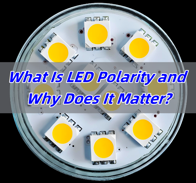
LED polarity refers to the direction in which an LED must be connected to a power source. Since LEDs are diodes, they allow current to flow in only one direction. This means that one leg of the LED must be connected to the positive side of the power supply, while the other must go to the negative side.

Each LED has two legs:

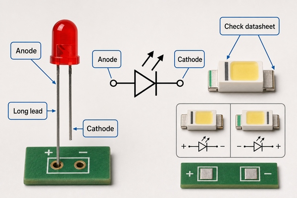
  • Anode (+): This is the positive leg. It needs to be connected to the positive terminal of the power source.
  • Cathode (-): This is the negative leg. It must connect to the negative terminal.

If the LED is wired incorrectly, it won’t light up because no current will flow through it. Some LEDs may even get damaged if too much voltage is applied in the wrong direction.

Do LEDs Have Polarity?

Yes, LEDs have polarity, and they must be connected correctly to function. Unlike traditional incandescent bulbs that work regardless of connection direction, LEDs only operate when the anode is connected to the positive voltage and the cathode to the ground.

The reason for this is that LEDs are light-emitting diodes. Diodes are semiconductor components that allow current to pass in one direction while blocking it in the other. When you reverse the polarity of an LED, it stops conducting electricity, which means it won’t produce light.

LED Polarity Symbol

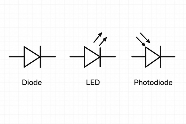
If you look at circuit diagrams, you’ll notice a special symbol used for LEDs. The LED polarity symbol is similar to a regular diode symbol but has two arrows pointing away from it to indicate light emission. Below are the common led polarity symbols used in the industry:

What Is LED Polarity and Why Does It Matter?

Are LED Light Bulbs Polarity Sensitive?

It depends on the type of LED light bulb.

  • AC-powered LED bulbs (like household LED light bulbs) are usually not polarity sensitive because they contain internal rectifiers that convert AC to DC.
  • DC-powered LEDs (such as those used in automotive applications, flashlights, or indicator lights) are polarity sensitive and will not work if connected incorrectly.

When working with DC-powered LED systems, checking the wiring is crucial. Many LED strips and car LEDs have markings to indicate which side should connect to positive and which should go to negative.

How Do You Identify the Polarity of an LED?

There are several ways to determine LED polarity:

1. Check the Lead Length

If it has leds, check the lead length is the most important method to identify:

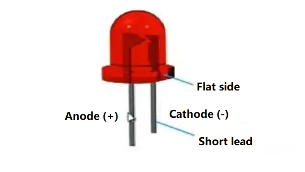
  • The longer lead is the anode (+).
  • The shorter lead is the cathode (-).
What Is LED Polarity and Why Does It Matter?

This method works well for new LEDs, but if the leads are trimmed, other methods may be needed.

2. Look for a Flat Edge

On many through-hole LEDs, the cathode side has a flat edge on the plastic casing. This marking helps quickly identify polarity. (Please refer above images of LED).

3. Inspect the Internal Structure

If you have a clear LED, you can look inside:

  • The larger internal piece is usually the cathode (-).
  • The smaller piece is the anode (+).

This method works well for transparent or diffused LEDs but is harder for small surface-mount LEDs.

4. Use a Multimeter

A digital multimeter with a diode test function can confirm polarity. When the red probe touches the anode and the black probe touches the cathode, the LED will glow slightly or show a voltage reading. If no reading appears, reverse the probes.

What Happens If LED Polarity Is Reversed?

If the LED is connected backward, it won’t light up. Unlike incandescent bulbs, which work in either direction, LEDs only allow current to flow in one way. Here are some common issues if LED polarity is reversed:

1. No Light Emission: Since LEDs are polarized components, they only work when connected correctly. If the polarity is reversed, current cannot flow, and the LED will not light up.

What Is LED Polarity and Why Does It Matter?

2. Potential Damage: In some cases, a reversed connection may cause damage. Excessive reverse voltage or current can harm the internal structure of the LED.

3. Overheating: Incorrect polarity may lead to improper current flow, generating excess heat. This can affect both the LED and nearby circuit components.

4. Short Circuit Risk: A severe polarity reversal could create a short circuit, which may harm the power source or other connected components.

5. Unstable Lighting: In rare cases, an incorrectly wired LED may flicker or dim unpredictably instead of staying off completely.

In most cases, a reversed LED will not get damaged unless the voltage is too high. However, some circuits use protection resistors or diodes to prevent issues caused by incorrect polarity.

Does LED Polarity Matter?

Yes, LED polarity matters because LEDs are diodes that function only when connected correctly. If you ignore polarity, the LED won’t work. In some cases, incorrect wiring can cause damage, especially in high-power LEDs or integrated circuits.

To avoid problems:

  • Always check the polarity markings before connecting an LED.
  • Use a multimeter if unsure.
  • Follow circuit diagrams carefully.

How to Check an LED with a Multimeter?

Using a multimeter is one of the easiest ways to test an LED’s polarity and functionality. Here’s a step-by-step guide:

1. Set the Multimeter to Diode Test Mode

Most digital multimeters have a diode test mode, usually marked with a diode symbol (a triangle pointing to a line). If your multimeter doesn’t have this mode, use the resistance (Ω) setting on the lowest range.

2. Identify the Probes

  • The red probe is the positive (+) lead.
  • The black probe is the negative (-) lead.

3. Connect the Probes to the LED Legs

Touch the red probe to one leg and the black probe to the other.

  • If the LED lights up faintly or shows a voltage reading (typically 1.8V to 3.5V, depending on the LED type), the red probe is on the anode (+), and the black probe is on the cathode (-).
  • If nothing happens, swap the probes and try again.

4. Interpret the Results

  • If the LED lights up, it means it is working, and you have identified the correct polarity.
  • If the LED doesn’t light up in either direction, it may be faulty or burned out.
  • If using the resistance mode, a working LED will show a resistance value in one direction and an infinite resistance (OL) in the other.

5. Testing Surface-Mount LEDs (SMD LEDs)

Since SMD LEDs are small and lack long leads, identifying polarity can be tricky. Many have a small marking on the cathode side. To test them:

  • Use fine-tip multimeter probes.
  • Hold the probes gently on the pads.
  • Observe if the LED lights up or if a voltage reading appears.

A multimeter is a quick and reliable tool to check LED polarity before installing it in a circuit.

Which Side of the LED Should You Put a Resistor?

A resistor is needed to control current flow and protect the LED. The resistor can go on either side of the LED—anode or cathode—without affecting polarity. However, placing it on the anode side (+) is common for consistency in circuit designs.

Without a resistor, the LED might receive too much current, which could shorten its lifespan or cause it to burn out.

FAQs

1. Can LED polarity be ignored?

No, LED polarity is essential for proper operation. If wired incorrectly, the LED will not work.

2. Do surface-mount LEDs have polarity?

Yes, surface-mount LEDs have polarity. Manufacturers usually mark the cathode with a dot or a line.

3. What happens if an LED is connected to AC power?

An LED without a rectifier will flicker or not work properly on AC power. A rectifier or resistor is needed for AC operation.

4. How do I fix a reversed LED?

Simply swap the connections. If the LED hasn’t been damaged, it should work fine.

5. Why do some LEDs have built-in resistors?

Built-in resistors simplify wiring by ensuring safe current levels. These LEDs can be directly connected to power sources without extra components.

You may also like

LED PCB: What Are the Different Types of LED PCB?
Friday, February 14th, 2025

LED PCB (Light Emitting Diode Printed Circuit Board) is an essential component in modern lighting solutions. This type of PCB integrates LEDs onto a circuit board to power and control them efficiently. In this article, we’ll explore the key aspects of LED PCBs, including how to design them, solder LEDs, and the different types available.

What is PCB in LED?

PCB in LED refers to the printed circuit board that hosts light-emitting diodes (LEDs). The purpose of the PCB is to provide electrical connections for the LEDs and facilitate heat dissipation, which is crucial for maintaining their performance and longevity. LED PCBs can be made from various materials, but aluminum-based PCBs are often preferred due to their excellent heat dissipation properties.

How Do You Add LED to PCB?

Adding an LED to a PCB is a simple process, but it requires attention to detail. First, the LED components are placed on the board in a specific pattern. Then, the LED leads are connected to the copper traces on the PCB using soldering. The PCB design ensures that the correct electrical pathways are established, enabling the LED to light up when powered. The placement of the LEDs on the PCB also plays a crucial role in the overall performance, affecting light distribution and heat management.

How Do You Solder LED with PCB?

Soldering LEDs onto a PCB involves several key steps. Begin by preparing the PCB, ensuring the copper pads are clean and ready for soldering. Next, position the LED onto the PCB in the correct orientation. Using a soldering iron, heat the pad and the LED lead, applying solder to form a secure electrical connection. It’s important to avoid overheating the LED, as excessive heat can damage the component. For high-density PCBs, such as SMD (Surface-Mounted Device) LED PCBs, using a reflow oven or wave soldering can improve precision and efficiency.

How to Build an LED PCB Board Step by Step?

Building an LED PCB board involves several steps:

Design the PCB Layout: Use PCB design software to create the layout. Include positions for the LEDs and traces for electrical connections.

Choose the Right Material: Select materials based on heat dissipation needs. For higher power LEDs, consider using aluminum PCBs.

Etch the PCB: After printing the design onto a copper-clad board, use an etching process to remove excess copper, leaving behind the circuit traces.

Apply Solder Paste: For SMD LED boards, apply solder paste to the pads where the LEDs will be placed.

Place the LEDs: Position the LEDs on the pads using a pick-and-place machine or manually, depending on the complexity of the design.

Solder the LEDs: Use a soldering iron or reflow oven to attach the LEDs securely to the board.

Testing: Finally, test the board to ensure proper function. This includes verifying electrical connections and light output.

How Much Amperage Can LED PCB Handle?

The amount of amperage an LED PCB can handle depends on several factors, including the type of LED, the design of the PCB, and the materials used. A standard LED typically operates at around 20mA, but high-power LEDs may require more amperage. To ensure safety and optimal performance, it’s crucial to design the PCB to accommodate the required current, using larger traces or heat dissipation features when necessary. For example, a typical 12V LED PCB board may handle around 1 to 2A, depending on the number of LEDs and their power requirements.

What Materials Make Up a Flexible LED PCB (Flex Circuit)?

Flexible LED PCBs, often referred to as flex circuits, are made from a combination of flexible base materials like polyimide or polyester film, which allow them to bend and conform to various shapes. The base material is coated with a thin layer of copper, which forms the electrical pathways for the LEDs. To ensure durability, the PCB may also include protective layers such as solder mask and a topcoat. The flexibility of these boards makes them ideal for applications that require curved or compact installations, such as in wearable devices or automotive lighting.

What Are the Different Types of LED PCB?

Firstly, Classification Based On Substrate Material

A. FR4 Standard PCB

Characteristics: Low cost, mature technology, but poor heat dissipation.

Applications: Low-power LEDs (e.g., indicator lights, decorative light strips).

B. Metal-Based PCB (MCPCB)

Characteristics: Uses a metal layer (usually 1-3mm thick) for rapid heat transfer, preventing LED light degradation.

Applications: High-power LEDs (e.g., automotive headlights, industrial lighting, stage lighting).

C. Ceramic PCB

Characteristics: Ultra-high thermal conductivity, heat resistance, good insulation, but very high cost.

Applications: UV LEDs, laser diodes, aerospace lighting.

D. Flexible PCB

Characteristics: Flexible, thin, suitable for non-flat installations.

Applications: Curved screen backlighting, wearable devices (e.g., smart wristbands), automotive interior ambient lighting.

Secondly, Classification Based On Packaging Technology

A. SMD (Surface-Mount Device) LED PCB

Characteristics: Compact, suitable for automated production, supports high-density layouts.

Applications: LED TV backlighting, advertising displays, general lighting modules.

B. COB (Chip-on-Board) LED PCB

Characteristics: High luminous efficiency, no glare, low thermal resistance.

Applications: Photography light, surgical shadowless lights, high-lumen street lights.

C. HDI (High-Density Interconnect) PCB

Characteristics: Uses micro-holes and blind/buried vias for fine circuit traces, supporting complex circuit designs.

Applications: Mini/Micro LED display driver boards, ultra-thin lighting modules.

What Is the Difference Between White and Black PCB LED Strips?

When it comes to LED PCB strips, the color of the PCB itself can affect both aesthetics and performance. White PCBs are the most common, offering a clean, neutral look that works well with most environments. They also reflect light better, improving the brightness and efficiency of the LEDs. On the other hand, black PCB LED strips are often chosen for their sleek, modern appearance. The black surface absorbs more light, which can reduce the reflection of stray light, creating a more focused illumination. Additionally, black PCBs tend to provide better thermal management due to their heat-absorbing properties.

In summary, LED PCBs are integral to modern lighting technology, offering a wide range of possibilities for various applications. From designing your own 12V LED PCB to understanding the differences between aluminum and flexible types, there’s a lot to learn about this versatile component. Whether you need a custom LED PCB or are interested in SMD LED PCBs, the technology behind them continues to evolve, making it easier to integrate LEDs into a multitude of devices.

At EBest Circuit (Best Technology), we specialize in providing high-quality LED PCBs tailored to your specific needs. Our experienced team ensures that every product meets the highest standards, delivering efficient, long-lasting solutions. For details or inquiries, feel free to contact us at sales@bestpcbs.com.

You may also like

Aluminum led pcb board manufacturers&Fast Delivery, Customization
Thursday, October 10th, 2024

Aluminum LED PCB board are almost everywhere in our lives. LED lights have become more popular than other lights in the field of lighting. LED PCBs usually use aluminum or metal core as substrates. Aluminum can dissipate heat effectively and there is no need to use a heat sink, so the PCB can effectively dissipate a lot of heat without problems.

What is aluminum led pcb board?

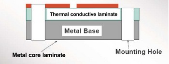
Aluminum LED PCB board is a special printed circuit board that is mainly used for LED lighting and other equipment that requires efficient heat dissipation. Unlike traditional FR-4 fiberglass boards, aluminum LED PCB boards use aluminum alloy as the substrate and have better thermal conductivity. This type of board usually consists of a three-layer structure: circuit layer (copper foil layer), insulation layer, and metal base layer.

Aluminum led pcb board manufacturers&Fast Delivery, Customization

The characteristic of aluminum LED PCB board is that it uses aluminum alloy material, which has excellent thermal conductivity and can quickly dissipate the heat generated when the LED is working. Compared with traditional FR-4 fiberglass boards, aluminum substrates have higher thermal conductivity and can carry higher currents, which are suitable for applications that require high power output.

In addition, aluminum substrates also have good electrical insulation and machining properties, which makes them also have a place in high-end applications.

In terms of application, aluminum LED PCB boards are mainly used in products such as LED lighting equipment and solar street lights that require efficient heat dissipation. Due to its excellent thermal conductivity and cost-effectiveness, aluminum substrates have quickly become the preferred material in these fields.

Why choose aluminum led pcb board?

The main reason for choosing aluminum-based PCB boards is that they are due to their excellent thermal conductivity and light and high-strength characteristics, which can effectively reduce the operating temperature of LED lights and improve their stability and reliability.

The advantages of aluminum-based PCB boards include:

  • Excellent thermal conductivity ‌: The aluminum substrate uses metal aluminum as the substrate, which has excellent thermal conductivity, can effectively conduct the heat generated by the LED when it is working, reduce the module operating temperature, extend the service life, and improve the power density and reliability. ‌
Aluminum led pcb board manufacturers&Fast Delivery, Customization
  • Lightweight and high strength ‌: The aluminum substrate material is light and has high strength, which is suitable for various complex environments and high-strength application scenarios ‌.
  • ‌Electromagnetic shielding performance‌: Aluminum substrate has good electromagnetic shielding performance, which can effectively reduce electromagnetic interference and improve the signal transmission quality of electronic equipment‌.
  • ‌High degree of customization‌: Aluminum substrate can be customized according to customer needs to meet the specific needs of different application scenarios‌.

Disadvantages of aluminum led pcb board

The main disadvantages of aluminum LED PCB board include high cost, difficult process, electrical strength and voltage resistance problems. ‌

First, the cost of aluminum LED PCB board is high. Compared with other materials, the price of aluminum substrate accounts for more than 30% of the product price, which increases the cost of the product to a certain extent‌.

Secondly, aluminum LED PCB board has certain difficulties in process. The current mainstream products are mainly single-sided boards, and the process of making double-sided boards is more difficult‌.

In addition, aluminum LED PCB boards are prone to problems in electrical strength and voltage resistance. Due to the characteristics of the material itself, the manufactured products may not meet the standards in terms of electrical strength and voltage resistance‌.

What are the types of LED PCB boards?

LED PCB boards are printed circuit boards for mounting LEDs. Their substrate materials mainly determine the thermal conductivity of LED PCBs. According to the different heat dissipation performance, LED PCB boards can be divided into 6 types.

  • Aluminum LED PCB: Aluminum LED PCB is the most common and cost-effective printed circuit board for LED lights, such as LED plant growth lights.
Aluminum led pcb board manufacturers&Fast Delivery, Customization
  • Copper-based LED PCB: Copper-based LED PCB is used for high-power LED lights, such as car headlights. The structure of ordinary copper-based LED PCB is the same as that of aluminum LED PCB, but the thermal conductivity is several times higher than that of aluminum LED PCB.
  • FR-4 LED PCB: If the LED light is used as daily household lighting and does not require much printed circuit board heat dissipation, FR-4 LED PCB can be a cost-effective printed circuit board choice. The price of FR-4 LED PCB is lower than other types of circuit boards.
  • Ceramic LED PCB: High-power LED lights, especially photography and pool lights, use ceramic LED PCB. Ceramic LED PCBs include aluminum nitride (AlN) PCBs, aluminum oxide (alumina) PCBs, boron oxide (BeO) PCBs, and silicon nitride (Si₃N₄) PCBs. The most common ceramic LED PCBs are AlN PCBs and alumina PCBs.
  • Hybrid substrate LED PCBs: The substrate materials of high-power LED PCBs can be mixed. Hybrid LED PCBs can have two or three substrate materials. And the different substrate materials are connected by phase change, that is, they are combined into a whole.
  • Flexible LED PCBs: Flexible PCBs with polyimide or polyester substrates are used for flexible LED light strips. Flexible LED PCBs can be used for mask lights, miner headlamps, and indoor/outdoor decorative light strips.

What is a SMD LED PCB board?

SMD LED PCBs are printed circuit boards for surface mounted LEDs (Surface Mounted Devices). ‌ SMD LED PCBs are LED chips packaged into lamp beads, which are then soldered on PCBs to make LED modules with different spacings. In this packaging method, each lamp bead is an independent point light source, which has the advantages of small size, large scattering angle, good luminous uniformity and high reliability.

The characteristics of SMD LED PCB board include:

  • 1. Principle of luminescence: When the current passes through the compound semiconductor, the electrons and holes combine to release energy and emit light, which belongs to cold luminescence, and the life span is about 50~100 times longer than that of tungsten filament bulbs, up to 100,000 hours.
  • 2. Fast response speed: The lighting response speed is faster than that of ordinary electric lights, about 3~400 nanoseconds.
  • 3. Energy saving and high efficiency: The electro-optical conversion efficiency is high, the power consumption is small, and it saves about 1/3~1/20 of the energy compared with the light bulb.
  • 4. Wide application: It is mainly used in lighting systems, decorations, electronic equipment indicators, backlights, displays and instruments.

How to make aluminum led pcb board?

LED circuit boards usually have good thermal conductivity, electrical insulation, and mechanical processing performance, and are mainly composed of metal-clad copper plates, conductive layers, and insulating layers.

The main manufacturing processes of LED PCB include:

  • 1. Raw material cutting
  • 2. Drilling
  • 3. Image transmission
  • 4. Etching
  • 5. Screen printing
  • 6. Solder mask
  • 7. Surface treatment
  • 8. V-shaped cutting
  • 9. Testing
  • 10. FQC and packaging

What do G, R, B and + mean on the LED PCB?

On the LED PCB, G, R, B and + represent the following meanings:

  • G stands for ground: It is the zero potential reference point in the circuit, and the potential of all other circuits is measured relative to the ground. The ground plays the role of providing reference potential and preventing mutual interference between circuits in the circuit.
  • R stands for red: In LED display screens, R usually refers to red light-emitting diodes, which are used to produce red light. Red light is part of the visible spectrum and is often used in color displays or lighting systems.
  • B stands for blue: Also in LED display screens, B stands for blue light-emitting diodes, which are used to produce blue light. Blue light, together with red and green light, can synthesize various colors and is widely used in color display technology.
  • + represents positive supply voltage: In the circuit, the + symbol usually represents the positive supply, that is, the power supply end that provides positive voltage. This is an important part of the power supply in the circuit to ensure the normal operation of electronic components.

In short, aluminum-based LED PCB boards occupy an important position in the electronics field with their excellent heat dissipation performance, reliable electrical performance and high mechanical strength. With the continuous advancement of technology, it will continue to bring more efficient solutions to many industries such as lighting, display screens, and automotive electronics.

You may also like

In order to reduce the cost, can SinkPad PCB use aluminum base instead copper base for heat dissipation?
Wednesday, June 24th, 2020

SinkPad PCB is a type of Copper base PCB used in thermoelectric separation application. It generally used for high power LED, the pad of LED touch the copper base directly, so that the heat generated by LED will dissipate quickly, which can achieve the best heat dissipation and conduction.

sinkpad gerber
sinkpad gerber
sinkpad pcb
sinkpad pcb

In another words, it is a technology that require to increase the path of the LED pad to the copper base to accelerate the heat emission from the base material. The copper base is vital while it also cost higher.

Then in order to lower cost, can SinkPad PCB use aluminum base instead copper base for heat dissipation?

The answer is NO. As you can see the below manufacturing steps, the SinkPad will etch the copper base into convex platform with Copper Etching Solution, then hollow out the Double Layer FR4 PCB, and do lamination with the convex platform.
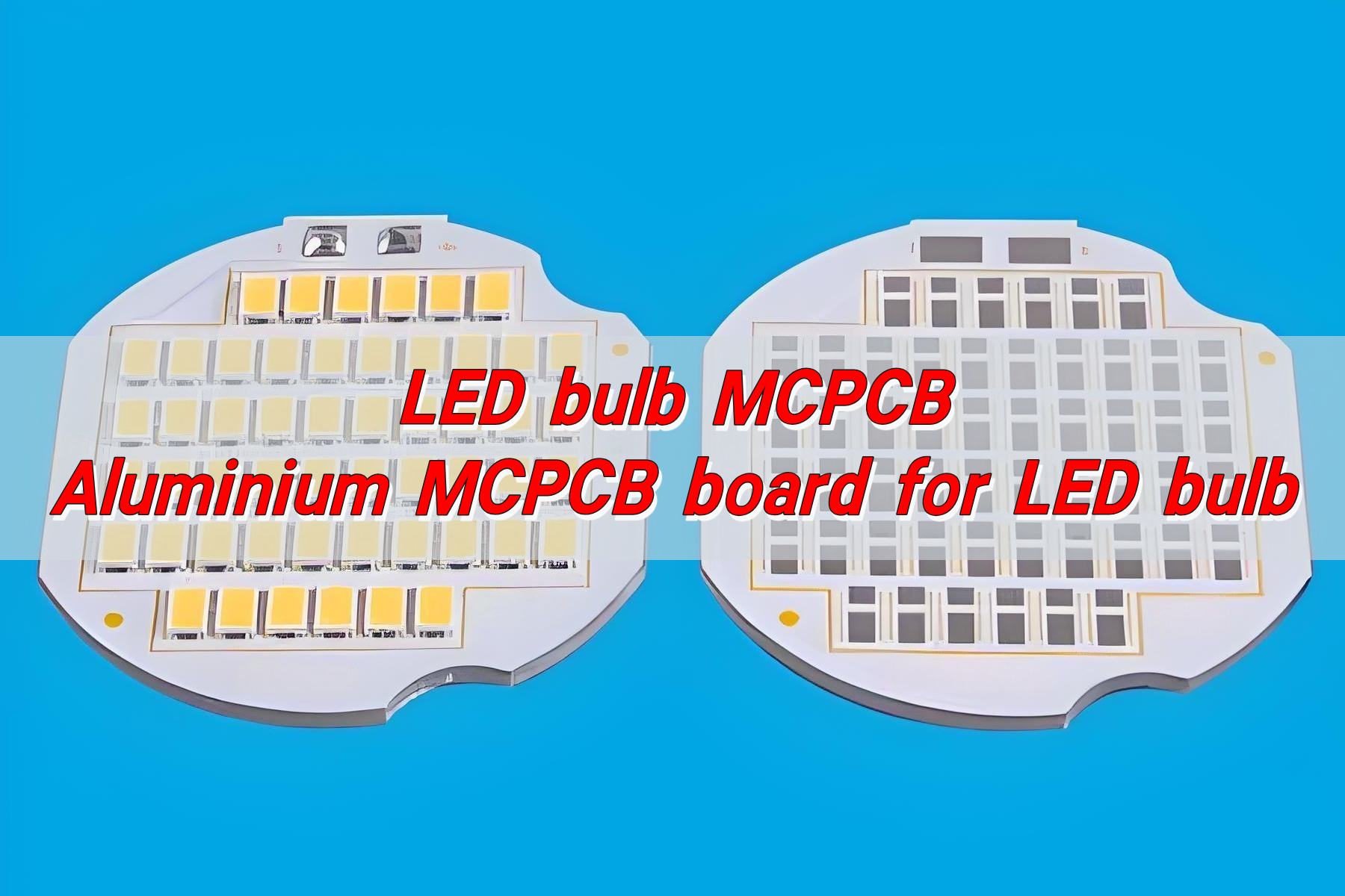
sinkpad pcb manufacturing steps

However, regarding of current technical conditions, since aluminum or aluminum alloy cannot directly react with acid, the reaction process is too complex and difficult to control, which will increase the difficulty of etching the LED pad platform. Considering the scrap rate, the process of etching LED pad platform with aluminum is more complex and the overall cost is higher.
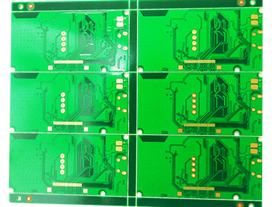
You may also like

Aluminum PCB LED Strip
Friday, March 20th, 2020

With the development of LED technology, LED power keeps increasing. This is closely related to heat dissipation. In order to resolve heat dissipation of LED with big power, aluminum-based copper-clad laminate is highly applied in led strip field.

Aluminum PCB(metal-based heat dissipation board) is a kind of unique metal-based copper-clad laminate. It has good head conductivity, electrical insulation and machining performance. Single-sided aluminum pcb consists of three layers of structures:circuit layer(copper foil), insulation layer and metal-based layer. Circuit layer requires large current-carrying capability, so we should use thick copper foil(generally 35um to 280um). The insulation layer for heat conduction is the core technology of aluminum pcb. It is general composed of special polymer filled with special ceramic. Small heat resistance, excellent viscoelasticity and anti-aging are all its advantages. And it is also able to bear mechanical and heat stress. Metal-based layer is the supporting component of aluminum pcb, and it needs to have high heat conductivity, so we generally use aluminum board, or copper board(which can provide higher conductivity). And it is suitable for regular machining such as drilling, punching and cutting. Techniques include gold plating, solder levelling, osp, ENIG, lead-free ROHS and so on.

single-layer-mcpcb-stackup

Aluminum pcb is commonly seen in LED products and has two sides(the front side and the reverse side). The white face is used to solder LED pin, and the other face presents natural color. It is generally painted with thermal conductivity paste and then contacted with heat conduction part. LED aluminum pcb is mainly used in power amplified mixed integrated circuits for STK series, motor cycles, automobile and electronics field.

There are many kinds of aluminum pcb for led tube, which varies based on the length and width of led tube. Aluminum pcb for led tube is popular with people due to its good quality, and durable and energy-saving features.

led strip
led strip

Aluminum pcb for led tube can save electricity as high as 70%. The light intensity of 12W Led tube is equal to 40w fluorescent tube. The service life of LED tube is is more than 10 times that of general fluorescent tube. It can be free of maintenance. Also, there is no need to change LED tube, barratter and starter frequently.

Generally, fluorescent tube has high temperature inside and needs to be used for more than 10 hours everyday in most cases. This problems are perfectly resolved by aluminum pcb for led tube.

If you have any queries, comments or suggestions on aluminum pcb for led, welcome to leave your message.

You may also like