PCB manufacturing PCB manufacturing
Home > Blog

custom led pcb

Rigid PCB 5V Addressable RGB Strip
Friday, July 3rd, 2026

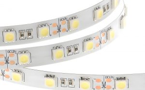
A rigid PCB 5V addressable RGB strip is a straight or shaped FR4 LED module where each RGB pixel can be controlled individually through a digital data signal. It is a better choice than a flexible LED strip when the product needs mechanical stability, predictable solder quality, stronger connector retention, or a custom board shape for an OEM lighting assembly.

The biggest engineering risks are not the RGB effect itself. The real risks are voltage drop, copper width, LED current, data signal integrity, heat, connector rating, and whether the supplier can test every pixel before shipment.
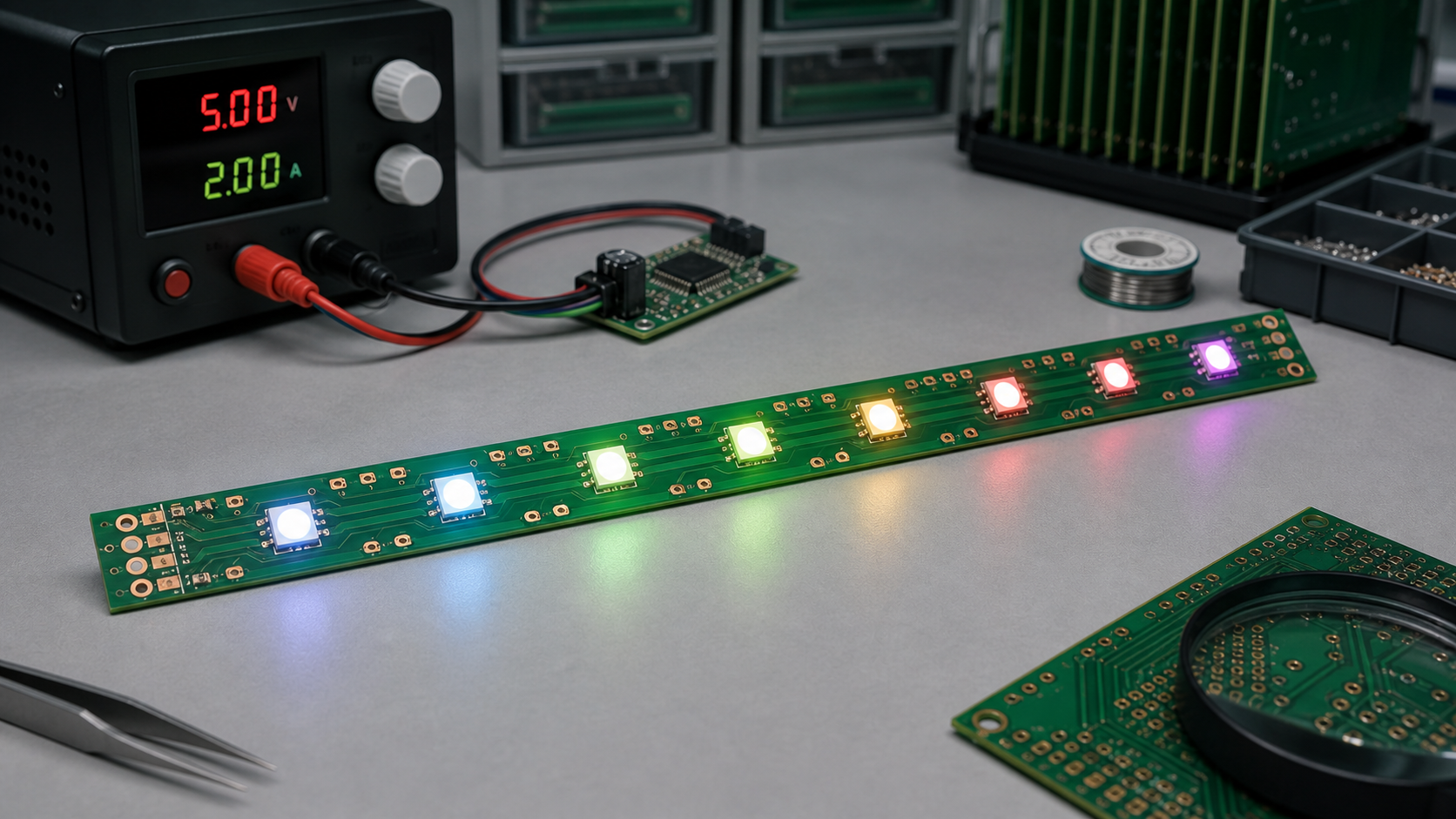
Rigid PCB 5V addressable RGB strip powered from a bench supply during engineering review
A 5V addressable RGB rigid PCB strip needs both optical design and careful power distribution.

Quick Answer: When Should You Use This Type of LED PCB?

Use a rigid PCB 5V addressable RGB strip when you need individually controlled RGB pixels on a stable board that can be mounted, screwed, snapped, or assembled into a product repeatedly.

Decision PointRigid PCB 5V Addressable RGB Strip Fits WhenWatch Out ForBuyer or Engineering Note
Product structureThe LED module is fixed inside a housing, display, fixture, machine, or sign.Do not use rigid PCB where the strip must bend after assembly.Confirm screw holes, edge clearance, and connector location early.
Control methodEach LED or pixel group needs individual color control.Some LEDs have strict timing and reset requirements.Match the controller firmware to the LED IC, such as WS2812B or SK6812.
PowerThe system already uses 5V DC or has a reliable 5V regulator.Long strips can suffer voltage drop and color shift.Plan power injection pads and wide 5V/GND copper.
ManufacturingYou need repeatable SMT assembly and full pixel testing.Poor reflow control can damage LEDs or create color inconsistency.Ask for optical and electrical test records.
CustomizationYou need custom length, pitch, mounting holes, connectors, or shape.Small design changes affect panelization and cost.Provide mechanical drawings together with Gerber and BOM files.

What Makes It Different from a Flexible Addressable LED Strip?

A rigid PCB strip uses a hard board material, commonly FR4, instead of a bendable flexible circuit. This changes mechanical performance, solder joint stability, mounting options, and heat spreading.

ItemRigid PCB Addressable RGB StripFlexible Addressable RGB StripPractical Difference
Mechanical behaviorStable and non-bendingBendable and easy to route around curvesRigid PCB is better for repeatable mounting and fixture integration.
Assembly stabilityGood SMT support and flatnessCan be affected by flex handling and adhesive backingRigid board is easier to fixture during production testing.
Connector strengthBetter for terminal blocks, board-to-wire, or board-to-board connectorsOften uses solder pads or light-duty connectorsImportant for OEM products with repeated assembly.
Thermal pathCan use wider copper and mounting contact to a housingDepends heavily on flex copper and installation surfaceRigid PCB may be easier to cool in enclosed products.
Custom shapeCan be routed, slotted, drilled, or made into modular sectionsBetter for long continuous curved pathsChoose based on mechanical design, not only LED type.

Common Related LED and PCB Options

Most buyers comparing this product also compare LED IC type, voltage, board material, pixel density, and connector style. The table below helps avoid mixing terms that sound similar but lead to different designs.

Item / Related TermWhat It MeansWhen It AppliesHow It DiffersBuyer or Engineering Note
WS2812B RGB stripCommon 5V addressable RGB LED with integrated control circuitDecorative lighting, indicators, small displays, OEM modulesOne data line controls chained pixelsCheck timing, data direction, and maximum current during full white.
SK6812 RGB or RGBW stripAddressable LED family often used for RGB or RGBW lightingProjects needing RGBW or alternate package optionsFirmware settings may differ from WS2812BConfirm RGB/RGBW order before production.
5V addressable LED stripLow-voltage strip where pixels are digitally controlledShort runs, controller-driven effects, individual pixel controlHigher current than 12V or 24V for the same powerPlan power injection for long or high-density layouts.
12V addressable stripHigher-voltage addressable lighting optionLonger wiring runs or lower current distributionMay use grouped pixels or different driver designCheck whether every LED is individually addressable.
Rigid FR4 LED PCBHard PCB substrate used for LED mountingOEM modules, panels, fixtures, displays, machine lightingStronger but not bendableSpecify thickness, copper weight, solder mask color, and mounting holes.
Aluminum LED PCBMetal-core PCB for better thermal performanceHigher power or heat-sensitive lighting modulesDifferent cost, drilling, insulation, and routing constraintsUse when heat is a stronger concern than routing complexity.

How a 5V Addressable RGB Strip Works

Each addressable RGB LED package includes RGB emitters and a small control circuit, so the controller sends serial data through the strip and each pixel passes the remaining data to the next LED.

With common LED families such as WS2812B and SK6812, the board usually has 5V, GND, data input, and data output paths. The PCB designer must route power rails wide enough for current, maintain clean data routing, place input/output pads clearly, and protect the strip from assembly mistakes.
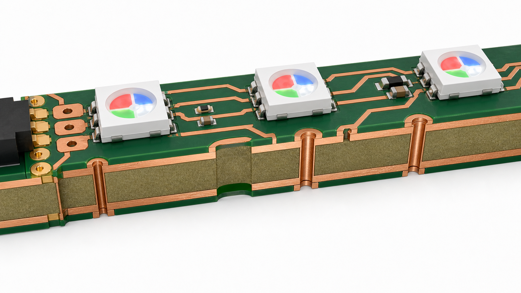
Cutaway view of a rigid PCB RGB LED strip with copper rails, vias, FR4 core, and addressable LED packages
Wide 5V and GND copper paths are critical because addressable RGB LEDs can draw high current at full brightness.

Power Design: 5V, Current, and Voltage Drop

Power distribution is the most common failure point in 5V addressable RGB strips because low voltage means higher current for the same wattage.

When all pixels show bright white, every RGB channel can draw current. The far end of a long strip may receive less than the input voltage because copper traces, wires, connectors, and solder joints all add resistance. The visible symptoms are dim LEDs, yellowish white, random flicker, reset behavior, or color mismatch between the near and far ends.

Power Design Checklist

  • Estimate worst-case current: Calculate full-white current from LED datasheets and safety margin.
  • Use wide 5V and GND rails: Do not route high-current power as thin signal traces.
  • Add power injection pads: Long strips should have feed points at intervals, not only one input end.
  • Check connector rating: Connector current rating must match the real strip load.
  • Measure voltage at the far end: Test under full-brightness patterns, not only colorful demo effects.
  • Consider copper weight: Higher current may require wider copper, thicker copper, or shorter segments.
  • Plan heat path: High brightness in an enclosed product needs thermal evaluation.

PCB Design Requirements for Rigid RGB Strips

The PCB layout should be designed around current flow, LED placement accuracy, optical alignment, and assembly test access.

Design AreaRecommended Engineering FocusCommon MistakeSupplier Check
LED pitchKeep pitch consistent for visual uniformityChanging pitch without updating optics or housingAsk for SMT placement tolerance and first-article photos.
Copper railsUse wide 5V and GND routing, with enough copper near connectorsThin rails causing voltage drop and heatReview Gerber copper width before production.
Data lineRoute cleanly from DIN to DOUT, with clear direction markingConfusing input and output pads during assemblySpecify data direction in silkscreen and test fixture.
Test padsAdd accessible 5V, GND, DIN, DOUT, and segment test padsNo way to isolate a failing LED chainAsk whether the factory can test every strip with a fixture.
PanelizationUse rails, tabs, V-cut, or routing based on strip shapeWeak tabs breaking LED solder joints during depanelingReview depaneling method with the PCB supplier.
Mounting holesKeep copper and LEDs away from screw stress zonesCracking solder joints near mounting pointsConfirm mechanical drawing with tolerances.

LED Selection: WS2812B, SK6812, RGB, or RGBW

The LED IC should be selected by controller compatibility, color requirement, package size, supply voltage, brightness, white channel needs, and availability.

WS2812B-style LEDs are widely used for 5V RGB addressable lighting, while SK6812 variants are common when RGBW or alternate packages are needed. The final choice should be verified against the controller firmware, color order, timing requirements, and supply chain stability. For production, do not substitute LED models without approval because the same footprint can still behave differently in color order, timing, reset behavior, brightness, or thermal performance.

Manufacturing and Assembly Concerns

Rigid addressable RGB strips look simple, but production quality depends on LED handling, solder paste control, reflow profile, depaneling, and full-function testing.

  • Moisture sensitivity: LED packages should be stored and baked according to supplier requirements when needed.
  • Polarity and orientation: RGB LEDs and data direction must be controlled by BOM, silkscreen, and AOI settings.
  • Solder paste volume: Too much paste can create bridging; too little can reduce mechanical strength.
  • Reflow profile: Overheating may damage LEDs or create color inconsistency.
  • Depaneling stress: Long narrow boards need careful support to avoid bending and solder joint cracks.
  • Functional testing: Every strip should be tested for red, green, blue, white, data-through, and current behavior.
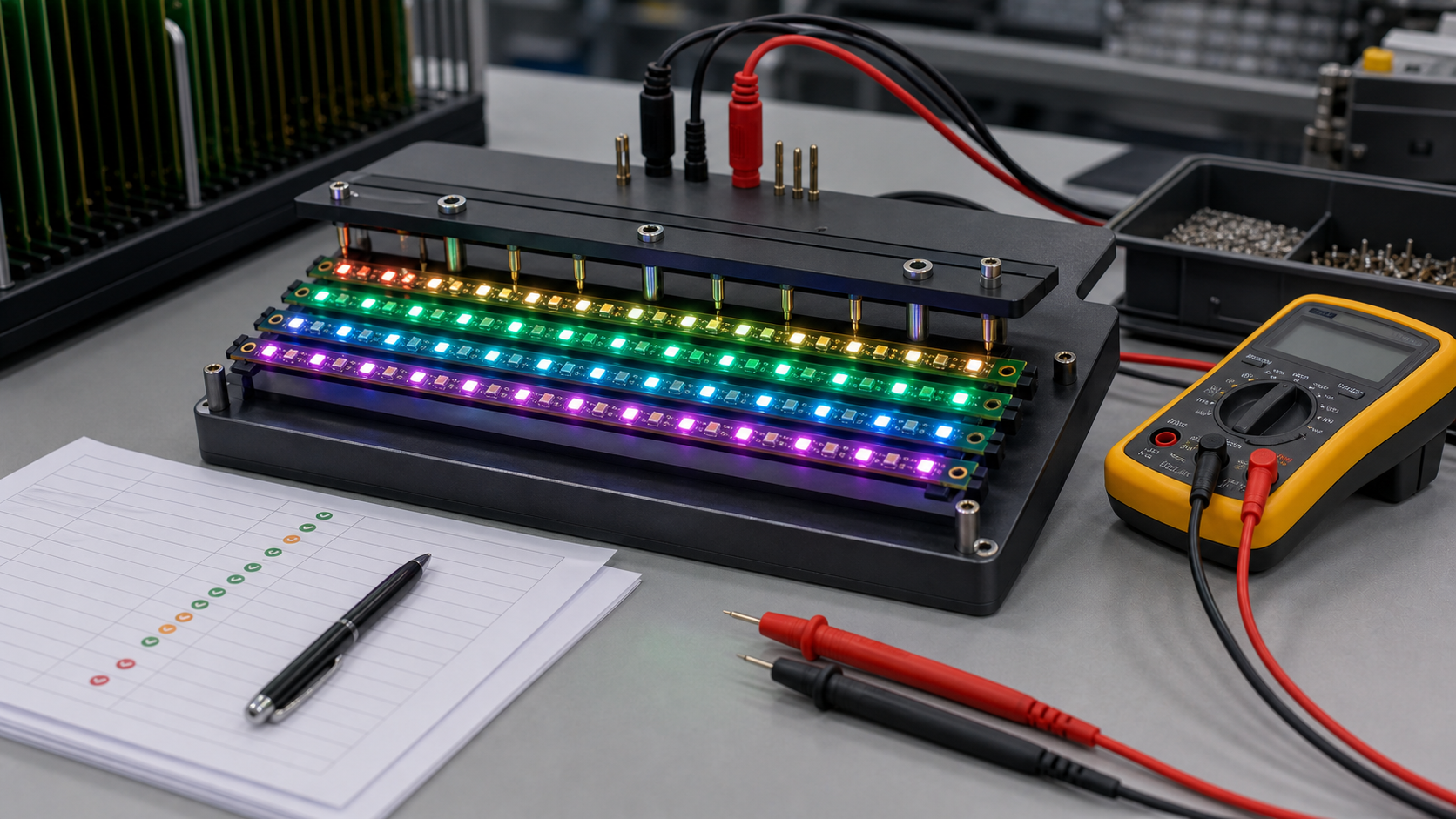
Factory test fixture checking multiple rigid PCB 5V addressable RGB strips with illuminated pixels
Production testing should verify color channels, data chain continuity, current, and visual consistency.

Testing Plan for Production Orders

A reliable supplier should test addressable RGB strips with both electrical and visual methods, not only a quick power-on check.

Test ItemPurposeWhat to Look ForWhy Buyers Should Care
Continuity testCheck 5V, GND, and signal pathsOpen circuits, shorts, reversed connectionsPrevents dead strips before LED test.
RGB channel testLight red, green, and blue separatelyWrong color order, missing channel, damaged LEDFinds assembly and LED defects early.
Full-white current testMeasure worst-case current drawOvercurrent, weak power rails, voltage dropImportant for power supply and connector selection.
Data-through testConfirm the signal passes from pixel to pixelBroken chain after one LED, bad solder joint, wrong orientationOne bad pixel can disable the downstream section.
Visual uniformity checkReview brightness and color consistencyDim pixels, color shift, uneven soldering or LED binsCritical for visible lighting products.

Procurement Checklist Before Ordering

Buyers should send both electrical and mechanical requirements, because a rigid PCB LED strip is part PCB, part lighting product, and part assembly module.

  • Target LED IC or accepted alternatives, such as WS2812B, SK6812, RGB, or RGBW.
  • Operating voltage, maximum current, expected brightness level, and duty cycle.
  • Board length, width, thickness, mounting holes, slots, and outline tolerance.
  • LED pitch, LED count, color order, and data direction.
  • Copper weight, surface finish, solder mask color, and silkscreen requirements.
  • Connector type, cable length, wire gauge, and current rating.
  • Testing method, acceptance criteria, packaging, and labeling requirements.
  • Whether the strip must pass product-level requirements such as EMC, flammability, or safety review.

Common Failure Modes

Most failures come from power distribution, poor LED soldering, data chain interruption, heat, or mechanical stress.

SymptomLikely CauseEngineering FixProduction Check
End pixels look dim or yellowVoltage drop along 5V/GND railsWider copper, shorter segments, or power injectionMeasure far-end voltage at full white.
Pixels flicker randomlyWeak data signal, poor grounding, or unstable powerImprove ground reference, routing, controller level, and power filteringRun dynamic color sequence tests.
All pixels after one LED failBroken data output or wrong LED orientationCheck LED direction, solder joints, and DOUT pathUse fixture test to locate chain break.
Connector gets hotCurrent exceeds connector or wire ratingUse higher-rated connector or multiple feedsThermal check during full-brightness burn-in.
Board cracks near mounting holeMechanical stress or poor hole clearanceAdd clearance, support, or change mounting structureReview mechanical drawing and screw torque.

FAQ

What is a rigid PCB 5V addressable RGB strip?

It is a non-flexible LED PCB module with individually controllable RGB pixels, usually powered by 5V DC and controlled through a digital data line. It is commonly used in OEM lighting modules, displays, indicators, and custom electronics.

Why choose rigid PCB instead of flexible LED strip?

Rigid PCB is better when the strip must mount flat, hold connectors firmly, maintain LED position, or pass repeatable assembly testing. Flexible strip is better when the installation needs bending around curves.

Is 5V enough for addressable RGB LEDs?

Yes, many addressable RGB LEDs are designed for 5V operation. The key is current planning. Long strips and high-density layouts need wide copper, suitable connectors, and often power injection.

How do I avoid voltage drop on a 5V RGB strip?

Use wide 5V and GND copper, keep high-current paths short, add power injection pads, choose connectors with enough current rating, and test the far-end voltage under full-white brightness.

Can every LED be individually controlled?

With common addressable RGB LEDs, each pixel can usually be controlled individually. However, some higher-voltage or cost-reduced products may group LEDs, so buyers should confirm pixel control before ordering.

What LED ICs are commonly used?

WS2812B and SK6812 families are common examples for 5V addressable RGB or RGBW products. The final choice should match the controller, color order, firmware timing, package, brightness, and availability.

Do rigid RGB strips need test pads?

Yes. Test pads for 5V, GND, DIN, DOUT, and segment points make production testing and fault diagnosis much easier, especially when one LED can interrupt the downstream data chain.

What copper weight should I use?

It depends on current, trace width, strip length, board temperature, and allowed voltage drop. For high-current strips, ask the PCB supplier to review copper width and current path before production.

Can a rigid PCB RGB strip be waterproof?

The PCB itself is not automatically waterproof. Waterproofing may require conformal coating, silicone encapsulation, housing design, or sealed connectors. Each method affects heat, repairability, and optical appearance.

What files should I send to a supplier?

Send Gerber files, BOM, pick-and-place file, mechanical drawing, LED specification, connector requirements, testing requirements, target quantity, packaging needs, and any controller compatibility details.

Can the same design use RGBW LEDs?

Possibly, but RGBW LEDs may have different pinout, current, package, firmware settings, color order, and optical requirements. Do not substitute RGBW without redesign review.

What should be tested before mass production?

Test RGB channels, full-white current, data-through continuity, far-end voltage, visual uniformity, connector heating, mounting fit, and controller compatibility before releasing mass production.

Final Recommendation

A rigid PCB 5V addressable RGB strip is a strong choice when you need a stable, custom, individually controlled lighting module for an OEM product. The design should be reviewed as a complete electrical, mechanical, optical, and manufacturing system, not just as a row of LEDs.

If you’re sourcing reliable PCB/PCBA manufacturing, including OEM, ODM, prototyping, mass production, or custom engineering solutions, reach out to our engineering team for technical support and a quote at sales@bestpcbs.com.

You may also like

Custom LED PCB, LED PCB Manufacturer
Thursday, April 24th, 2025

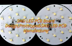
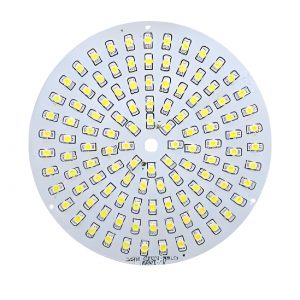
In the rapidly evolving world of electronics and lighting, the demand for custom LED PCB is climbing fast. Whether you’re building industrial lights, consumer gadgets, or smart wearables, choosing a dependable LED PCB manufacturer can set your project apart in terms of quality, efficiency, and performance.

If you’re looking for high-performance lighting solutions with reliable circuitry, you need more than just a product. You need a trusted partner. EBest Circuit (Best Technology) is that partner. We are a leading LED PCB manufacturer with over 18 years of hands-on experience. We specialize in crafting custom LED PCB solutions that go beyond ordinary lighting components. Our team supports industries ranging from automotive and aerospace to medical and consumer electronics. Whether you need a DIY LED PCB board, SMD LED PCB board, or help with LED PCB board replacement, we offer unmatched quality, guidance, and long-term value.

What Is a Custom LED PCB?

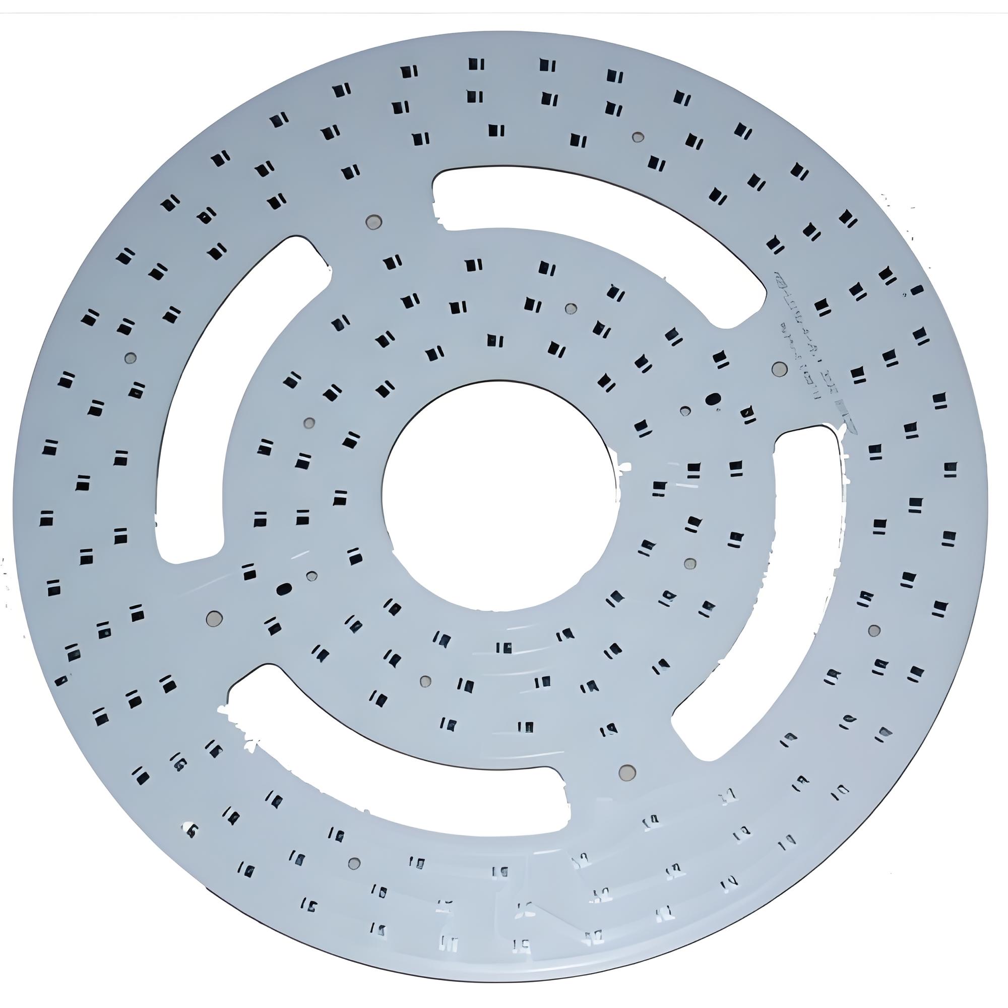
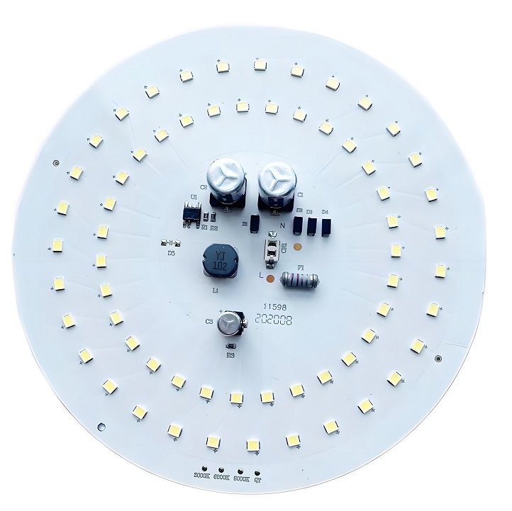
What is a custom LED PCB? A custom LED PCB is a printed circuit board designed to support and connect light-emitting diodes in a specific configuration. Unlike off-the-shelf boards, these are tailored to fit your product’s shape, power needs, and environmental demands.

Whether it’s a curved light strip, a compact torch design, or a large-format display backlight, a custom LED PCB meets your unique criteria with pinpoint accuracy. It’s not just about making it fit—it’s about optimizing performance.

Why Customization Matters in LED PCB Design?

Every application has different priorities. Some need intense brightness. Others demand heat control in confined spaces. A few require flexible materials or rigid aluminum cores. A standard LED PCB board simply can’t’ cater to all these needs.

With custom LED PCB design, you have full control over:

  • LED type and layout
  • Trace width and thickness
  • Copper weight
  • Heat dissipation paths
  • Voltage and current specifications
  • Mounting hole placements
  • Base material selection

What Services Does EBest Circuit (Best Technology) Offer?

At EBest Circuit (Best Technology), we’ve been making LED PCBs for decades. We offer full support—from idea to finished board. Whether you need 1 piece for testing or 10,000 pieces for production, we’ve got you covered.

We manufacture:

  • Aluminum LED PCBs: Great for heat control
  • FR4 LED PCBs: Good for low-power applications
  • Ceramic LED PCBs: Perfect for small, hot environments
  • Copper-based PCBs: Excellent for high current
Custom LED PCB, LED PCB Manufacturer

We also provide:

  • Free DFM checks (design for manufacturing)
  • Quick samples (5–7 days turnaround)
  • Full testing (visual, electrical, thermal)
  • Component sourcing and assembly

Our team understands both electronics and lighting design, so your custom LED PCB will meet your real-world needs.

Our LED PCB Capabilities

ItemCapabilities
Layer Count1 – 10 Layers
Max Board Dimension24*64″(610*1625mm)
Min Board Thickness0.6mm
Max Board Thickness4.0mm
Conductor Thickness0.5oz – 10oz
Min Line Width/Line Space4/4mil (0.10/0.10mm)
Min Hole Diameter10mil (0.25mm)
Min Punch Hole Dia0.12″ (3.0mm)
Min Hole Spacing16mil (0.4mm)
Min PAD Ring(Single)3mil (0.075mm)
PTH Wall ThicknessNormal: 0.59mil (15um); HDI: 0.48mil (12um)
Min Solder PAD Dia14mil (0.35mm)
Min Soldermask Bridge8mil (0.20mm)
Min BAG PAD Margin5mil (0.125mm)
PTH/NPTH Dia TolerancePTH: ±3 mil (0.075mm); NPTH: ±2mil (0.05mm)
Hole Position Deviation±3mil (0.075mm)
Outline ToleranceCNC: ±6 mil (0.15mm); Die Punch: ±6 mil (0.1mm)
Max Aspect Ratio10:01
Surface TreatmentENIG, ENEPIG, HAL, HASL(LF), OSP, Tin Imm

Popular Applications of Custom LED PCBs

  • Street Lighting
  • Automotive Interiors and Headlights
  • Backlighting for Displays
  • Architectural and Accent Lighting
  • Medical Imaging Devices
  • Consumer Electronics
  • Agricultural Grow Lights

Different environments need different board types. For example, a grow light needs stable, long-term brightness, while a car brake light needs to handle vibration and heat.

How to Design a DIY LED PCB Board?

Designing your own LED PCB can be a fun and educational project. Here’s how to get started:

1. Pick your LED type: Decide how bright you want the light to be. Choose between small SMD LEDs or larger high-power ones.

2. Use design software: Free tools like EasyEDA or KiCad help you draw your circuit layout.

3. Decide on materials: If your LEDs will get hot, choose aluminum or copper as the base (though ceramic substrate has excellent thermal dissipation, but it is very expensive compared with aluminum or copper).

4. Draw your layout: Make sure LED placement is even. Place current paths (traces) wide enough to handle the power.

5. Add resistors: These control how much current goes through each LED.

6. Test your layout: Before making the board, simulate the circuit using the design software.

7. Order a prototype: Send your design to a PCB maker for a test run.

Tip: Always check the polarity of your LEDs before soldering—they only work one way!

What’s Inside an LED Circuit Board Diagram?

An LED circuit diagram shows how the board works. It’s like a map for your board.

You’ll see:

  • LEDs (usually marked with a triangle and line)
  • Power input (VCC) and ground (GND)
  • Resistors (to control current)
  • Drivers or ICs (for smart control, if used)

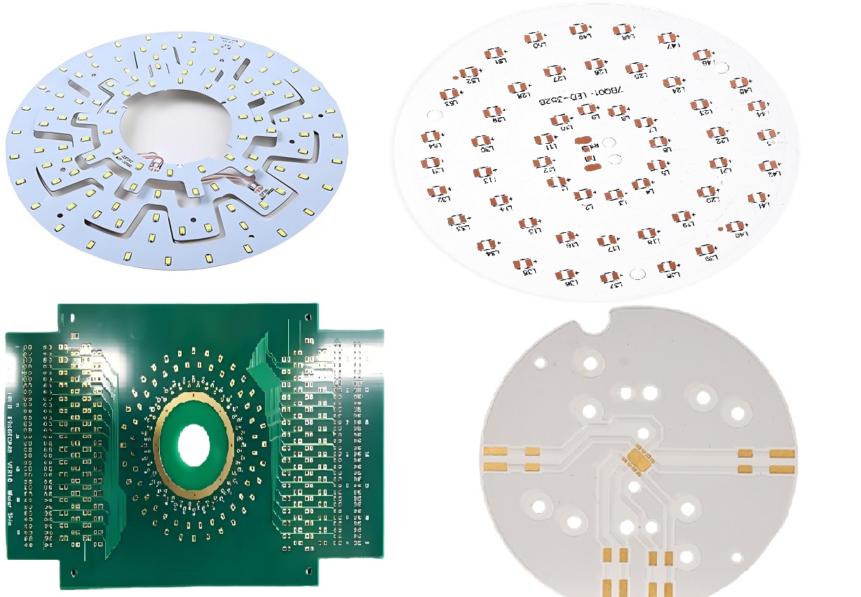
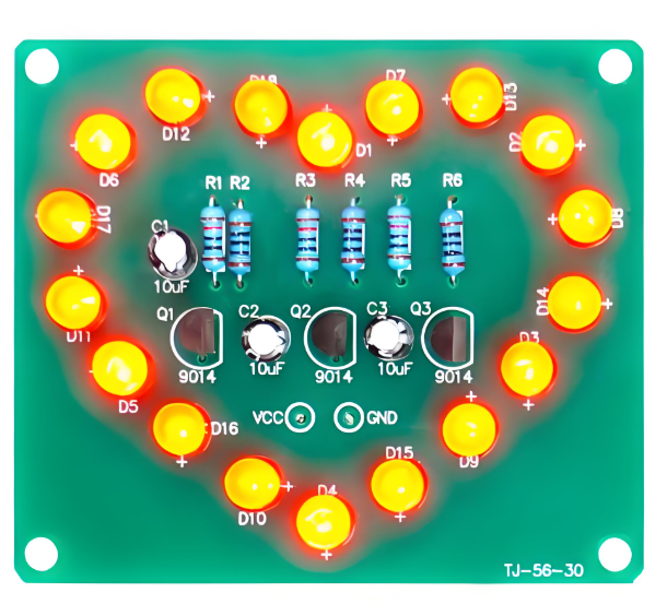
Here is a typical led circuit board diagram example:

LED Circuit Board Diagram

How to Choose the Right Base Material for Your LED PCB?

Choose the right material can help you save much time and money to revise or update the design. Nowadays, there are 5 types of base materials will be used in LED PCB design, each has unique properties and applications.

  • Aluminum: Best for cooling and cost-effective. Used in most LED lights.
  • FR4 (fiberglass): Cheap and easy to use. Works well for low-power lights.
  • Ceramic (AlN or BeO): Great at handling heat. Used in medical or high-precision tools. It always used in high-end applications, like aerospace or military.
  • Copper: Good conductor. Useful when you need a lot of power in a small space. But it has heavier weight among all materials.
  • Polyimide: Flexible material, always used in flexible devices.

Tip: If your LED gets warm to the touch, go with aluminum or copper. If it stays cool, FR4 is usually fine.

Key Considerations for LED PCB Strip Design

1. Current and voltage rating:

LED strips typically operate at standard voltages like 12V or 24V DC. Choosing the right voltage ensures consistent brightness and prevents overheating. For instance, a 24V strip loses less power over long runs compared to a 12V one—voltage drop is approximately 4–6% lower over a 5-meter run.

2. Copper thickness:

Standard copper thickness is 1oz, which is suitable for low-power strips. For high-current applications like industrial lighting, go for 2oz or more.

3. LED layout and spacing:

Spacing affects light uniformity and heat distribution. For example:

  • 60 LEDs/m offers a soft glow suitable for accent lighting.
  • 120 LEDs/m or higher gives a brighter, more uniform output, ideal for task lighting.

4. Solder mask color:

White and black solder mask are popular in led lighting design. White solder masks are preferred for LED strips because they reflect up to 80–90% of visible light, improving luminous efficiency. Black masks, on the other hand, absorb more heat and can reduce light output by up to 20% in reflective applications.

5. Thermal vias:

If you’re using a multi-layer PCB, thermal vias help transfer heat from the surface layer to the internal layers or to the aluminum base.

Whether you’re working on decorative lighting or industrial-grade illumination, these choices make a visible difference.

Common Mistakes to Avoid in LED PCB Board Replacement

Replacing an LED PCB board may seem simple, but several mistakes can lead to costly repairs or system failure. Here are a few things to watch out for:

1. Not matching the voltage and current ratings:

2. Poor heat management:

3. Wrong LED type or color temperature:

4. Using the wrong connectors or soldering techniques:

5. Skipping testing after installation:

EBest Circuit (Best Technology) offers replacement services and supports compatibility checks to avoid costly errors.

How to Get a Quote for a Custom LED PCB?

Getting a quote for a custom LED PCB is simple if you prepare the all information. Most of manufacturers are happy if you can provide following files in the quote phase.

1. Gerber files and BOM

2. Detailed Specifications:

  • PCB size and shape
  • Number of layers
  • Copper thickness
  • Base material (e.g., aluminum, FR4)
  • Solder mask color
  • Surface finish (ENIG, HASL, etc.)

3. LED details: mention the LED type, power rating, quantity, and placement.

4. Order quantity and lead time: higher volumes usually mean lower cost per unit. Also, let the supplier know if you need it urgently.

5. Special requirements: if you need waterproofing, specific connectors, or certifications (RoHS, UL, etc.) or IPC class III, include those details too.

If you have this information already, reach out EBest Circuit (Best Technology), and our sales team will review your files and send a best quotation within 12 hours.

You may also like

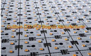
Custom LED PCB, Custom LED PCB Boards Manufacturer
Tuesday, March 25th, 2025

Custom LED PCB have revolutionized lighting solutions across industries, offering tailored performance for specialized applications. Let’s explores custom LED PCB from materials to manufacturing processes, helping you make informed decisions for your next project.

At Best technology, we focus on one stop solution PCB solution for custom LED PCB over 18 years. We support ODM and OEM customized LED PCB boards, and we have our own exclusive electronic supply chain, which can achieve low MOQ, multiple varieties, fast delivery, and professional engineers provide free technical services online one-to-one 24 hours a day. Welcome to contact us sales@bestpcbs.com if you have any request for custom LED PCB.

What Is LED PCB?

A ‌LED PCB (Light-Emitting Diode Printed Circuit Board)‌ is a specialized board designed to power and control LED arrays. Unlike standard PCBs, these boards prioritize ‌thermal management‌, ‌high-density layouts‌, and ‌optical precision‌ to maximize LED performance and lifespan. Custom LED PCBs are engineered to meet specific requirements such as brightness, color temperature, and environmental resilience.

Custom LED PCB

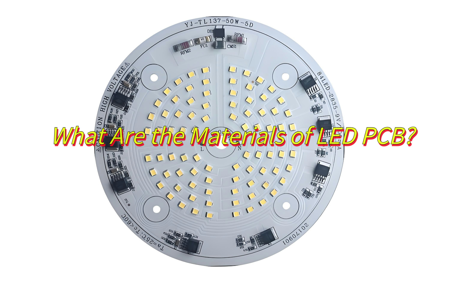
What Are the Materials of LED PCB?

  • ‌Aluminum Base-Excellent heat dissipation, cost-effective, best for automotive lighting.
  • FR-4-Low cost, standard insulation, best for Consumer electronics.
  • Ceramic Base-Ultra-high thermal resistance, best for aerospace systems.
  • Flexible Base-Bendable, lightweight design, best for wearables, curved displays.
Custom LED PCB

What Are the Advantages of LED PCB?

  • High Reliability-Withstand extreme temperatures (-40°C to 150°C), humidity, and vibrations.
  • Superior Thermal Management-Aluminum and ceramic substrates dissipate heat 5-10x faster than FR-4, preventing LED degradation.
  • Design Flexibility-Custom shapes, sizes, and LED densities (up to 200 LEDs/sq. inch) for unique applications.
  • Energy Efficiency-Optimized circuits reduce power loss by 15-30% compared to traditional wiring.
  • Cost-Effective Scaling-Bulk production cuts costs by 40-60% for large orders.

What Are the Application of Custom LED PCB?

Here are main application of custom LED PCB:

  • Automotive headlights
  • Airport runway landing lights
  • Street lighting
  • Highway tunnel lighting
  • Photovoltaic (solar) lighting
  • Flashlights and lanterns
  • Traffic and signal lighting
  • Lighting in hospital operating rooms
  • High growth plant lighting

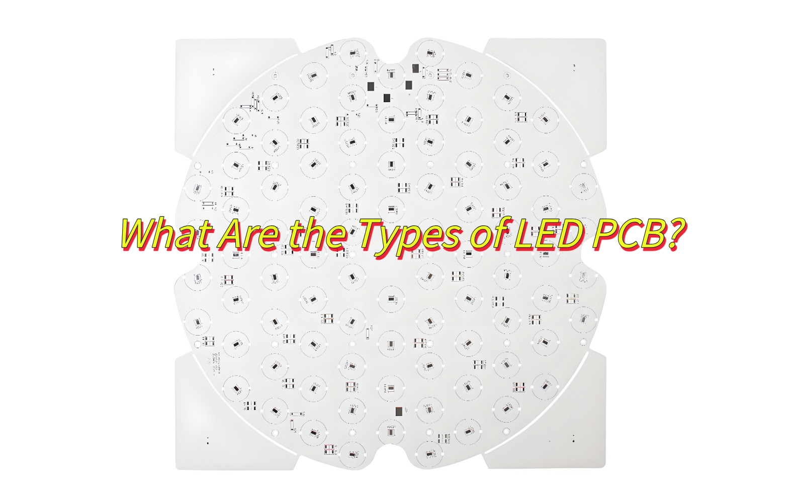
What Are the Types of Custom LED PCB?

Here are types of custom LED PCB board:

Single-layer PCB:

  • Features: Single-sided wiring, lowest cost, suitable for simple circuits‌.
  • Applications: Basic LED signs, small lighting modules‌.

‌Double-layer PCB:

  • Features: Double-sided wiring + via connection, support for medium-complexity circuits‌.
  • Applications: Smart home lighting, advertising light boxes‌.

‌Multi-layer PCB (4 layers and above):

  • Features: High-density wiring, integrated heat dissipation layer and signal layer‌.
  • Applications: Industrial-grade LED control systems, automotive smart headlights‌.
Custom LED PCB Board

Manufacturing Process of Custom LED PCB Board

  1. Aluminum substrate cutting‌: Cut aluminum substrate according to design size (heat dissipation optimization)
  2. PCB manufacturing‌: Drilling → Copper deposition → Etching → Surface treatment (Spray tin/immersion gold)
  3. SMT patch‌: Fully automatic patch machine solders LED chips, resistors, capacitors and other micro components
  4. ‌Surface protection: Coating green oil to protect the circuit to prevent oxidation and solder short circuit‌.
  5. Surface treatment: Surface spray tin or immersion gold treatment to enhance welding performance and corrosion resistance‌
  6. Plug-in welding‌: Manual/mechanical supplementary installation of large-size plug-ins (such as connectors)
  7. Functional test‌: Power on to detect LED brightness, color temperature and circuit stability
  8. Final inspection and shipment‌: Appearance inspection + packaging shockproof treatment

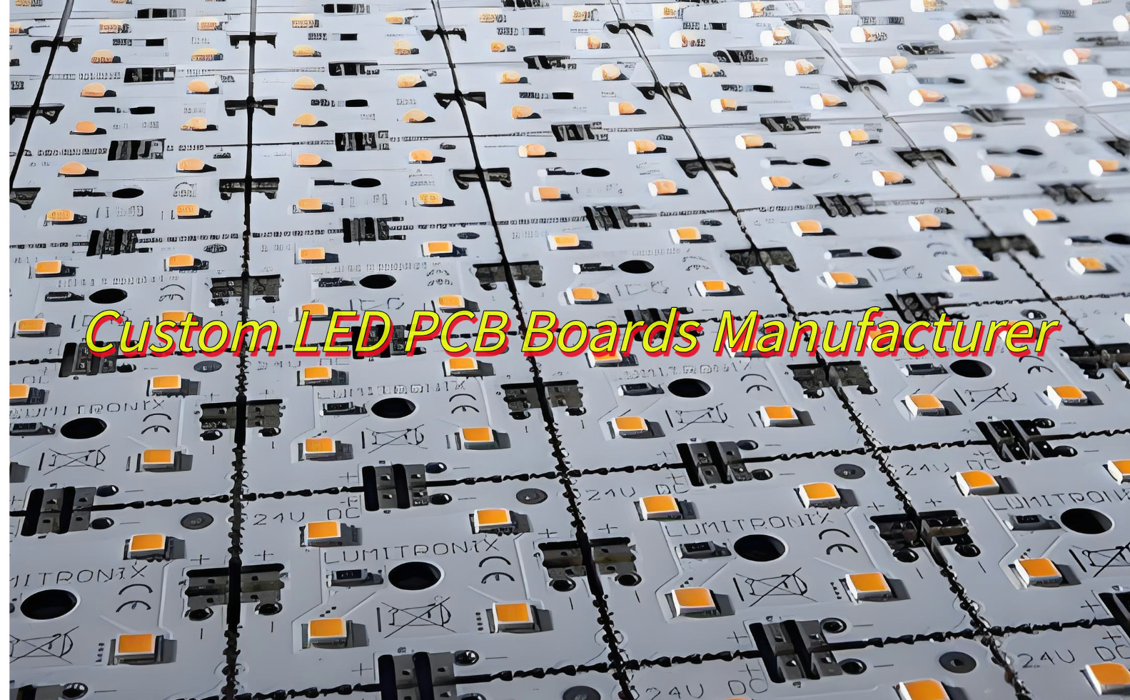
Custom LED PCB Boards Manufacturer

As a custom LED PCB boards manufacturer, EBest Circuit (Best Technology), establish on June 28, 2006, is a Hong Kong registered company whom focus on custom LED PCB boards manufacturing. We are dedicated to be your best partner of advance and custom LED PCB boards manufacturer. Here are more information about us:

  • Quality assurance both for our products and before/after-sales service.
  • Accept small order and mixed order, samples are welcomed.
  • Discounts are offered base on large order quantities with custom led PCB.
  • Great variety of LED PCB products with competitive price, welcome OEM and ODM.
  • Provide expedited custom LED PCB board prototyping service.
Custom LED PCB Boards Manufacturer

If you are interested in our service, welcome to contact us at any time.

FAQs of Custom LED PCB

1.How to improve heat dissipation in custom LED PCBs?‌

Use aluminum substrates with 2-3 oz copper layers and thermal vias.

2.What’s the minimum order quantity (MOQ) of custom led PCB?‌

EBest Circuit (Best Technology) accept one piece MOQ for custom led PCB prototyping.

3.Can custom LED PCBs be repaired?‌

Yes, but rework costs often exceed replacement costs for high-density boards.

4.How much does a custom LED PCB cost?‌

Price range from $0.50-$20 per piece normal FR-4 board.

5.What’s the lifespan of custom LED PCBs?‌

Properly designed boards last 50,000-100,000 hours (5-11 years).

To sum up, that’s all about custom LED PCB. Start your project today by partnering with a certified PCB manufacturer to turn your design into reality.

You may also like

LED PCB: What Are the Different Types of LED PCB?
Friday, February 14th, 2025

LED PCB (Light Emitting Diode Printed Circuit Board) is an essential component in modern lighting solutions. This type of PCB integrates LEDs onto a circuit board to power and control them efficiently. In this article, we’ll explore the key aspects of LED PCBs, including how to design them, solder LEDs, and the different types available.

What is PCB in LED?

PCB in LED refers to the printed circuit board that hosts light-emitting diodes (LEDs). The purpose of the PCB is to provide electrical connections for the LEDs and facilitate heat dissipation, which is crucial for maintaining their performance and longevity. LED PCBs can be made from various materials, but aluminum-based PCBs are often preferred due to their excellent heat dissipation properties.

How Do You Add LED to PCB?

Adding an LED to a PCB is a simple process, but it requires attention to detail. First, the LED components are placed on the board in a specific pattern. Then, the LED leads are connected to the copper traces on the PCB using soldering. The PCB design ensures that the correct electrical pathways are established, enabling the LED to light up when powered. The placement of the LEDs on the PCB also plays a crucial role in the overall performance, affecting light distribution and heat management.

How Do You Solder LED with PCB?

Soldering LEDs onto a PCB involves several key steps. Begin by preparing the PCB, ensuring the copper pads are clean and ready for soldering. Next, position the LED onto the PCB in the correct orientation. Using a soldering iron, heat the pad and the LED lead, applying solder to form a secure electrical connection. It’s important to avoid overheating the LED, as excessive heat can damage the component. For high-density PCBs, such as SMD (Surface-Mounted Device) LED PCBs, using a reflow oven or wave soldering can improve precision and efficiency.

How to Build an LED PCB Board Step by Step?

Building an LED PCB board involves several steps:

Design the PCB Layout: Use PCB design software to create the layout. Include positions for the LEDs and traces for electrical connections.

Choose the Right Material: Select materials based on heat dissipation needs. For higher power LEDs, consider using aluminum PCBs.

Etch the PCB: After printing the design onto a copper-clad board, use an etching process to remove excess copper, leaving behind the circuit traces.

Apply Solder Paste: For SMD LED boards, apply solder paste to the pads where the LEDs will be placed.

Place the LEDs: Position the LEDs on the pads using a pick-and-place machine or manually, depending on the complexity of the design.

Solder the LEDs: Use a soldering iron or reflow oven to attach the LEDs securely to the board.

Testing: Finally, test the board to ensure proper function. This includes verifying electrical connections and light output.

How Much Amperage Can LED PCB Handle?

The amount of amperage an LED PCB can handle depends on several factors, including the type of LED, the design of the PCB, and the materials used. A standard LED typically operates at around 20mA, but high-power LEDs may require more amperage. To ensure safety and optimal performance, it’s crucial to design the PCB to accommodate the required current, using larger traces or heat dissipation features when necessary. For example, a typical 12V LED PCB board may handle around 1 to 2A, depending on the number of LEDs and their power requirements.

What Materials Make Up a Flexible LED PCB (Flex Circuit)?

Flexible LED PCBs, often referred to as flex circuits, are made from a combination of flexible base materials like polyimide or polyester film, which allow them to bend and conform to various shapes. The base material is coated with a thin layer of copper, which forms the electrical pathways for the LEDs. To ensure durability, the PCB may also include protective layers such as solder mask and a topcoat. The flexibility of these boards makes them ideal for applications that require curved or compact installations, such as in wearable devices or automotive lighting.

What Are the Different Types of LED PCB?

Firstly, Classification Based On Substrate Material

A. FR4 Standard PCB

Characteristics: Low cost, mature technology, but poor heat dissipation.

Applications: Low-power LEDs (e.g., indicator lights, decorative light strips).

B. Metal-Based PCB (MCPCB)

Characteristics: Uses a metal layer (usually 1-3mm thick) for rapid heat transfer, preventing LED light degradation.

Applications: High-power LEDs (e.g., automotive headlights, industrial lighting, stage lighting).

C. Ceramic PCB

Characteristics: Ultra-high thermal conductivity, heat resistance, good insulation, but very high cost.

Applications: UV LEDs, laser diodes, aerospace lighting.

D. Flexible PCB

Characteristics: Flexible, thin, suitable for non-flat installations.

Applications: Curved screen backlighting, wearable devices (e.g., smart wristbands), automotive interior ambient lighting.

Secondly, Classification Based On Packaging Technology

A. SMD (Surface-Mount Device) LED PCB

Characteristics: Compact, suitable for automated production, supports high-density layouts.

Applications: LED TV backlighting, advertising displays, general lighting modules.

B. COB (Chip-on-Board) LED PCB

Characteristics: High luminous efficiency, no glare, low thermal resistance.

Applications: Photography light, surgical shadowless lights, high-lumen street lights.

C. HDI (High-Density Interconnect) PCB

Characteristics: Uses micro-holes and blind/buried vias for fine circuit traces, supporting complex circuit designs.

Applications: Mini/Micro LED display driver boards, ultra-thin lighting modules.

What Is the Difference Between White and Black PCB LED Strips?

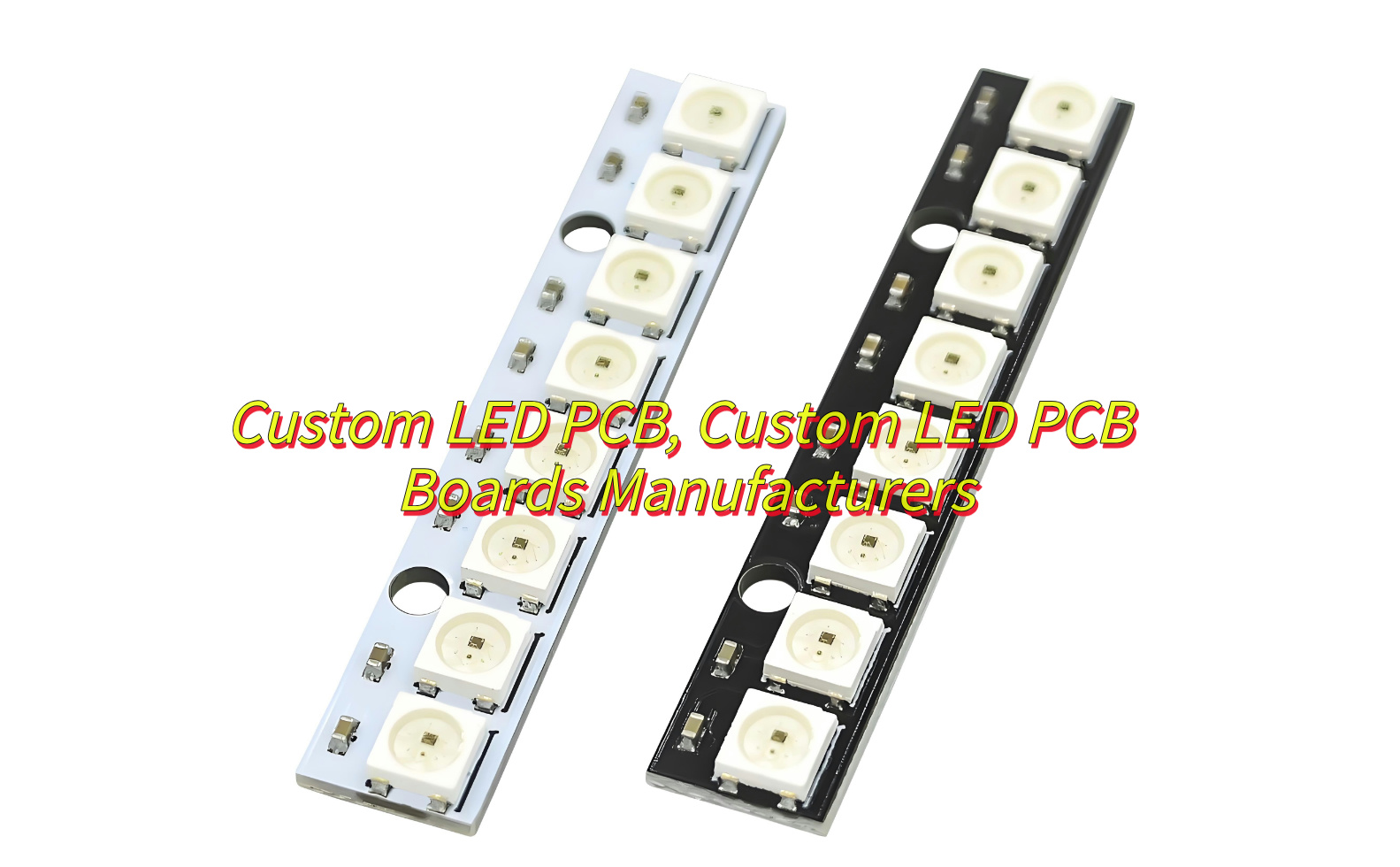
When it comes to LED PCB strips, the color of the PCB itself can affect both aesthetics and performance. White PCBs are the most common, offering a clean, neutral look that works well with most environments. They also reflect light better, improving the brightness and efficiency of the LEDs. On the other hand, black PCB LED strips are often chosen for their sleek, modern appearance. The black surface absorbs more light, which can reduce the reflection of stray light, creating a more focused illumination. Additionally, black PCBs tend to provide better thermal management due to their heat-absorbing properties.

In summary, LED PCBs are integral to modern lighting technology, offering a wide range of possibilities for various applications. From designing your own 12V LED PCB to understanding the differences between aluminum and flexible types, there’s a lot to learn about this versatile component. Whether you need a custom LED PCB or are interested in SMD LED PCBs, the technology behind them continues to evolve, making it easier to integrate LEDs into a multitude of devices.

At EBest Circuit (Best Technology), we specialize in providing high-quality LED PCBs tailored to your specific needs. Our experienced team ensures that every product meets the highest standards, delivering efficient, long-lasting solutions. For details or inquiries, feel free to contact us at sales@bestpcbs.com.
You may also like