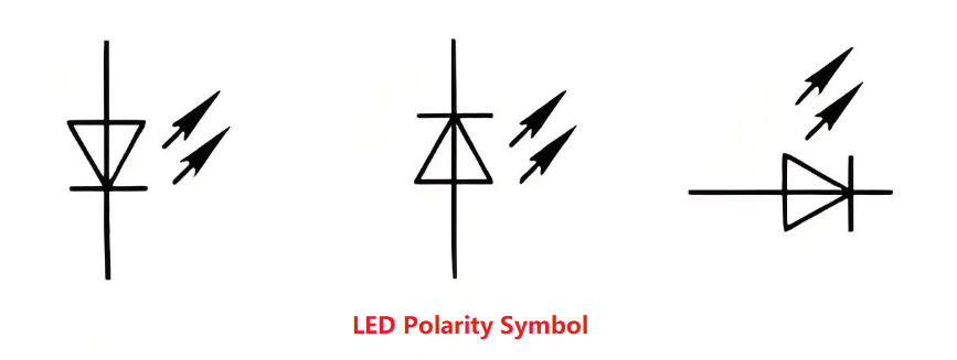
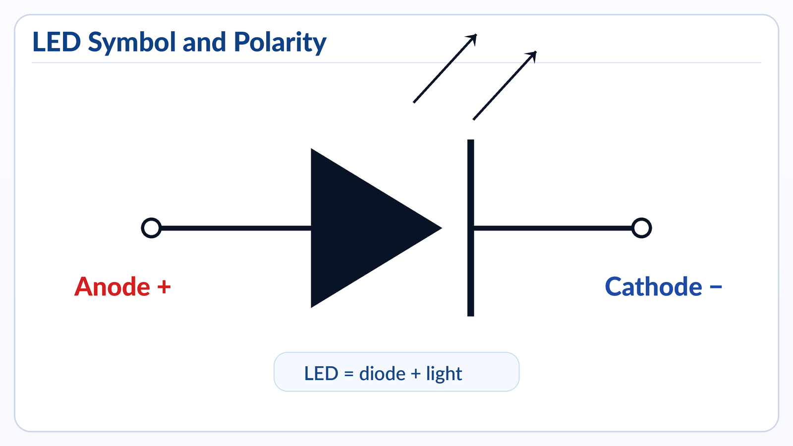
An LED symbol is the standard schematic mark for a light-emitting diode. It looks like a normal diode symbol with two small arrows pointing outward, showing that the component emits light when current flows in the correct direction.
For PCB work, this topic matters because an LED is a polarized component. The anode and cathode must match the circuit and the PCB footprint. A reversed LED may not light, may cause debugging confusion, or may fail if the reverse voltage or current is too high.
Best Technology provides PCB design, PCB prototyping, mass production, component sourcing, and PCB assembly services for LED-related electronics and other custom circuit board projects.
What Is the Symbol for LED?
The symbol for an LED is a diode symbol with two arrows pointing away from it. The diode part shows that current flows mainly in one direction, while the outward arrows show light emission.
In a schematic, the LED symbol usually has two sides:
| LED Symbol Part | Meaning | Practical Note |
|---|---|---|
| Anode | Positive side | Current enters here in normal operation |
| Cathode | Negative side | Usually marked by the vertical line/bar side |
| Two outward arrows | Light output | This separates LED from a normal diode |
| Diode body | One-way current behavior | LED will not work like a resistor |
A simple way to remember it: LED = diode + light arrows.
In circuit diagrams, the LED is often labeled as D, LED, LED1, D1, or sometimes LD. The exact reference designator depends on the designer’s naming rule, but in most PCB documentation, LED components are grouped with diodes because they are part of the diode family.
LED Symbol on PCB
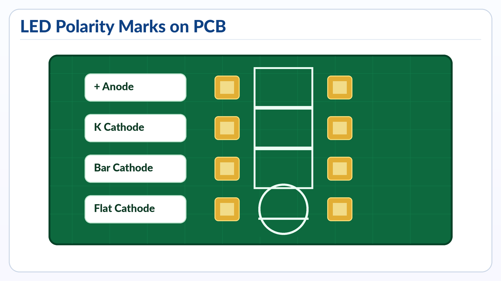
The LED symbol on PCB is usually printed on the silkscreen layer to help assembly workers place the LED in the correct direction. It may appear as a diode symbol, a small outline with a flat side, a “+” mark, a “K” mark, or a cathode bar.
A schematic symbol tells the electrical function. A PCB footprint tells the physical placement. They must match.
Common PCB LED polarity marks include:
| PCB Marking | What It Usually Means | Reliability of Marking |
|---|---|---|
| “+” mark | Anode / positive side | Very clear when used correctly |
| “K” mark | Cathode side | K comes from “Kathode” |
| Bar line | Cathode side | Common in diode-style markings |
| Flat side on outline | Cathode side for many through-hole LEDs | Useful but package-dependent |
| Square pad | Often pin 1, but not always polarity | Must check library rule |
| Dot or chamfer | Pin 1 or cathode/anode depending package | Confirm with datasheet |
For through-hole LEDs, the PCB may show a circular outline with one flat edge. This flat edge normally matches the flat side of the LED body, which is commonly the cathode. For SMD LEDs, the polarity mark is often a tiny notch, dot, bevel, green mark, or printed line on the package.
The most common mistake is assuming every PCB library uses the same polarity convention. In real production, this is risky. Some CAD libraries mark pin 1, while the LED datasheet may define pin 1 as cathode or anode depending on the package. Before release, the schematic symbol, PCB footprint, assembly drawing, pick-and-place file, and BOM should all be checked together.
Which Side of the LED Symbol Is Positive?
The positive side of the LED symbol is the anode. In the standard diode-style symbol, the anode is on the side without the vertical bar, and the cathode is on the side with the bar.
The easiest rule is:
Anode = positive side
Cathode = negative side
Cathode side = bar side in the symbol
In normal operation, conventional current flows from the anode to the cathode. That is why the LED only lights when it is forward-biased. If the anode is connected to a higher potential and the cathode is connected through the correct current-limiting path to a lower potential, the LED can turn on.
For real components, polarity can be checked in several ways:
| LED Type | Positive Side Clue | Negative Side Clue |
|---|---|---|
| Through-hole LED | Longer lead is usually anode | Shorter lead is usually cathode |
| Round through-hole LED | Smaller internal electrode often anode | Larger internal electrode often cathode |
| SMD LED | Datasheet defines anode mark | Package mark often identifies cathode |
| PCB footprint | “+” often marks anode | Bar or “K” often marks cathode |
Main Types of LED Symbols and Related Diode Symbols
The LED symbol belongs to the diode symbol family. Different diode types use similar base shapes, but each has extra marks that show its function.
| Symbol Type | Visual Feature | Meaning | Common PCB Use |
|---|---|---|---|
| Standard diode | Diode body with bar | One-way current flow | Rectification, reverse protection |
| LED | Diode body with two arrows pointing outward | Emits light | Indicators, displays, optocouplers, lighting |
| Photodiode | Diode body with arrows pointing inward | Detects light | Sensors, optical receivers |
| Zener diode | Diode symbol with bent cathode line | Voltage regulation/clamping | Reference, surge protection |
| Schottky diode | Modified cathode marking | Low forward voltage, fast switching | Power conversion, reverse protection |
| TVS diode | Suppression-style diode symbol | Transient protection | ESD and surge protection |
| Laser diode | LED-like symbol, often with laser indication | Coherent light output | Optical modules, sensors |
LED and photodiode symbols are often confused by beginners. The difference is direction of arrows. LED arrows point outward because light leaves the device. Photodiode arrows point inward because light enters the device.
On PCB silkscreen, not every diode type is printed with a full symbol. Some boards use short polarity marks only. For compact boards, especially HDI, wearable electronics, medical modules, and LED driver PCBs, there may be limited space for full silkscreen. In that case, the assembly drawing and component datasheet become even more important.
Which Symbol Is Correct for an LED?
The correct symbol for an LED is a diode symbol with two arrows pointing outward. A plain diode symbol is not technically wrong for showing one-way conduction, but it does not communicate the light-emitting function.
For professional schematics, the LED should use the dedicated LED symbol. This makes the circuit easier to read for engineers, technicians, purchasing teams, and assembly houses.
A correct LED symbol should show:
- The diode direction
- The cathode bar
- The light-emission arrows
- The reference designator, such as LED1 or D3
- The value or color, when needed
- The package or part number in the BOM
For example, an indicator LED might be labeled:
LED1, Green, 0603, 2.0V typical Vf, 20mA max
For a high-power LED, the documentation should be more detailed. It may include forward voltage range, rated current, luminous flux bin, color temperature, thermal pad requirements, and recommended soldering profile.
The symbol alone is not enough for manufacturing. It tells function and polarity, but the PCB assembler also needs the footprint, BOM, polarity mark, and placement data. A clean schematic symbol with a poor footprint can still cause assembly defects.
How to Identify LED?
You can identify an LED by checking the package shape, polarity marks, component label, datasheet, and diode-test behavior with a multimeter. For PCB assembly, the datasheet and BOM should always be the final reference.
Common LED identification methods:
| Method | How It Works | Best Use |
|---|---|---|
| Look at the circuit symbol | LED symbol has outward arrows | Reading schematic diagrams |
| Check PCB silkscreen | Find “LED,” “D,” “+,” “K,” or cathode bar | Board inspection |
| Inspect the LED body | Flat side or short lead often marks cathode | Through-hole LED identification |
| Use a multimeter diode mode | LED may glow faintly in forward direction | Bench testing |
| Check datasheet | Confirms pinout, polarity, package, voltage | Production and procurement |
| Compare BOM and placement file | Confirms exact part used | SMT assembly |
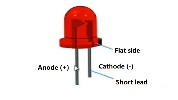
For through-hole LEDs, identification is usually simple. The longer leg is commonly positive, and the shorter leg is commonly negative. The flat side on the plastic lens often marks the cathode.
For SMD LEDs, visual identification can be harder. Some packages have a tiny green line, a beveled corner, a dot, or a T-shaped mark. But different manufacturers use different conventions. One 0603 LED may mark the cathode; another may mark the anode. That is why datasheet checking is not optional for mass production.
In PCB manufacturing, a good LED identification process includes component verification before assembly, first article inspection after SMT, and polarity confirmation during AOI or manual inspection. For LED lighting products, additional functional testing is usually needed because a visually correct component can still have color bin, brightness, or forward voltage mismatch issues.
What Is the Element Symbol for LED?
LED does not have a chemical element symbol because it is not a single element. LED stands for Light Emitting Diode, which is an electronic component made from semiconductor materials.
This question often appears because “symbol” can mean two different things:
| Term | Meaning |
|---|---|
| LED symbol | Schematic symbol used in circuit diagrams |
| Element symbol | Chemical abbreviation, such as Cu for copper or Si for silicon |
| Reference designator | PCB label, such as LED1, D2, or D5 |
| Package marking | Physical mark printed on the LED component |
An LED can contain materials such as gallium arsenide, gallium phosphide, gallium nitride, indium gallium nitride, or aluminum gallium indium phosphide, depending on color and performance. But the component itself is not represented by one chemical element symbol.
In schematic and PCB documentation, the more useful identifiers are the circuit symbol, reference designator, manufacturer part number, and package footprint. For procurement, the part number matters more than the generic name. For assembly, the footprint and polarity mark matter more than the visual symbol alone.
How to Tell Which LED Wire Is Positive?
For a typical through-hole LED, the longer wire is the positive side, also called the anode. The shorter wire is the negative side, also called the cathode.
You can also check the LED body. Many round LEDs have a flat side on the rim. That flat side usually marks the cathode. Inside the transparent lens, the larger metal cup is usually the cathode, while the smaller internal electrode is often the anode.
Here is a practical checklist:
| Clue | Usually Indicates |
|---|---|
| Longer lead | Anode / positive |
| Shorter lead | Cathode / negative |
| Flat side on LED body | Cathode / negative |
| Larger internal metal cup | Cathode / negative |
| PCB “+” mark | Anode / positive |
| PCB bar or “K” | Cathode / negative |
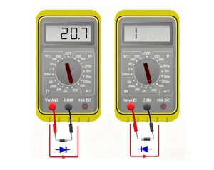
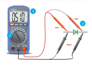
For new parts, these rules work well most of the time. For trimmed leads, recycled parts, custom LEDs, or already-mounted components, use a multimeter in diode mode. Connect the red probe to one lead and the black probe to the other. If the LED glows faintly or shows a forward voltage reading, the red probe is on the anode and the black probe is on the cathode.
Never test a bare LED directly with a high-current power supply unless you use a current-limiting resistor or a controlled LED tester. LEDs are current-driven devices. Too much current can damage the junction quickly.
What Happens If You Wire a LED Light Backwards?
If you wire an LED backwards, it will usually not light because it is reverse-biased. In low-voltage circuits, it may simply stay off. In higher-voltage or poorly protected circuits, reverse bias can damage the LED.
The result depends on the circuit:
| Situation | Likely Result |
|---|---|
| Low voltage with current limit | LED does not light |
| Reverse voltage above LED rating | LED may break down |
| No current-limiting resistor | LED may fail when corrected or during fault |
| LED array wired incorrectly | One LED may stop an entire string |
| High-power LED on MCPCB | Heat and electrical stress may cause early failure |
| Reverse polarity in finished PCBA | Functional test failure or field return |
Many small indicator LEDs have a limited reverse voltage rating, often around a few volts depending on the datasheet. Once reverse stress exceeds the rating, leakage current can increase and the LED junction may degrade. The component may not fail immediately, but its brightness, stability, or service life can be affected.
For PCB designers, reverse polarity risk can be reduced by adding clear silkscreen marks, using keyed connectors, checking schematic-to-footprint mapping, and including polarity inspection in the assembly process. For LED driver boards, protection design is also important, especially when connectors may be installed by end users.
What Is the Difference Between LED and LCD?
LED and LCD are different technologies. An LED emits light directly, while an LCD controls light but usually needs a backlight to be visible.
| Item | LED | LCD |
|---|---|---|
| Full name | Light Emitting Diode | Liquid Crystal Display |
| Basic function | Emits light | Controls light transmission |
| Needs backlight? | No for a single LED indicator | Usually yes |
| PCB role | Indicator, lighting source, display segment, backlight | Display module with driver circuit |
| Polarity | Yes, LED is polarized | LCD module has pin orientation and power requirements |
| Common use | Power indicator, status light, lamps, displays | Screens, meters, panels, instruments |
In everyday language, “LED display” and “LCD display” are sometimes used loosely. Many so-called LED TVs are actually LCD panels with LED backlighting. The LED is the light source, while the LCD panel forms the image.
On a PCB, an LED is normally treated as a diode component. An LCD is usually treated as a display module or connectorized assembly. It may include driver ICs, backlight LEDs, flexible cables, zebra connectors, or surface-mounted connectors. Their schematic symbols, footprints, BOM requirements, and inspection methods are different.
LED Symbol and PCB Polarity Design Tips
A correct LED circuit is not only about the schematic symbol. The PCB footprint, silkscreen, copper layout, resistor placement, and assembly documents must all support the same polarity rule.
For indicator LEDs, place the current-limiting resistor close enough to make the circuit easy to follow. For dense PCBs, keep the LED reference designator visible whenever possible. If the board has many LEDs in an array, use consistent orientation so inspection is faster.
For production-ready PCB files, check these points before release:
| Design Item | Good Practice | Why It Matters |
|---|---|---|
| Schematic symbol | Use true LED symbol with cathode bar | Avoids confusion with normal diode |
| Footprint polarity | Match datasheet pinout | Prevents reversed placement |
| Silkscreen | Mark “+,” “K,” bar, or flat side clearly | Helps manual and visual inspection |
| BOM | Include exact manufacturer part number | Avoids color/package mismatch |
| Pick-and-place file | Correct rotation and centroid | Reduces SMT placement errors |
| Assembly drawing | Show polarity for LED parts | Supports first article inspection |
| Test plan | Include LED function test | Catches reversed or wrong-color LEDs |
For SMD LEDs, rotation is a common production issue. A footprint may look symmetric, but the LED is electrically polarized. If the centroid file uses a different zero-degree orientation from the assembler’s machine library, the LED can be rotated incorrectly. This is why first article inspection is important before full production.
Common LED Symbol and Assembly Mistakes
LED-related PCB mistakes are often small, but they can create visible product defects. A reversed resistor may not matter, but a reversed LED usually matters immediately.
Common mistakes include:
| Mistake | Cause | Result | Prevention |
|---|---|---|---|
| Reversed LED footprint | Symbol pin mapping does not match package | LED does not light | Compare schematic, footprint, and datasheet |
| Wrong silkscreen mark | “+” placed on wrong pad | Assembly confusion | Review polarity on assembly drawing |
| Missing current-limiting resistor | LED connected directly to supply | LED burnout | Calculate resistor or use LED driver |
| Wrong LED color | BOM not specific enough | Visual mismatch | Include part number, wavelength, CCT, bin |
| Incorrect SMD rotation | Placement angle mismatch | Batch failure risk | Confirm first article before mass run |
| Weak thermal path | High-power LED on poor copper design | Brightness decay, heat damage | Use MCPCB, copper core PCB, or thermal vias as needed |
| No functional test | Visual inspection only | Hidden polarity or brightness issue | Add power-on LED test |
For high-power LED PCB design, thermal management becomes part of electrical reliability. The symbol may look simple, but the PCB structure may need aluminum PCB, copper core PCB, heavy copper copper paths, thermal vias, or direct thermal pad design. LED lifetime is strongly affected by junction temperature, so layout and material choice should not be treated as secondary details.
For small signal LEDs, the most useful improvement is documentation clarity. A clean polarity mark can save hours of troubleshooting in prototypes and reduce assembly questions in volume production.
LED Symbol in Real PCB and PCBA Projects
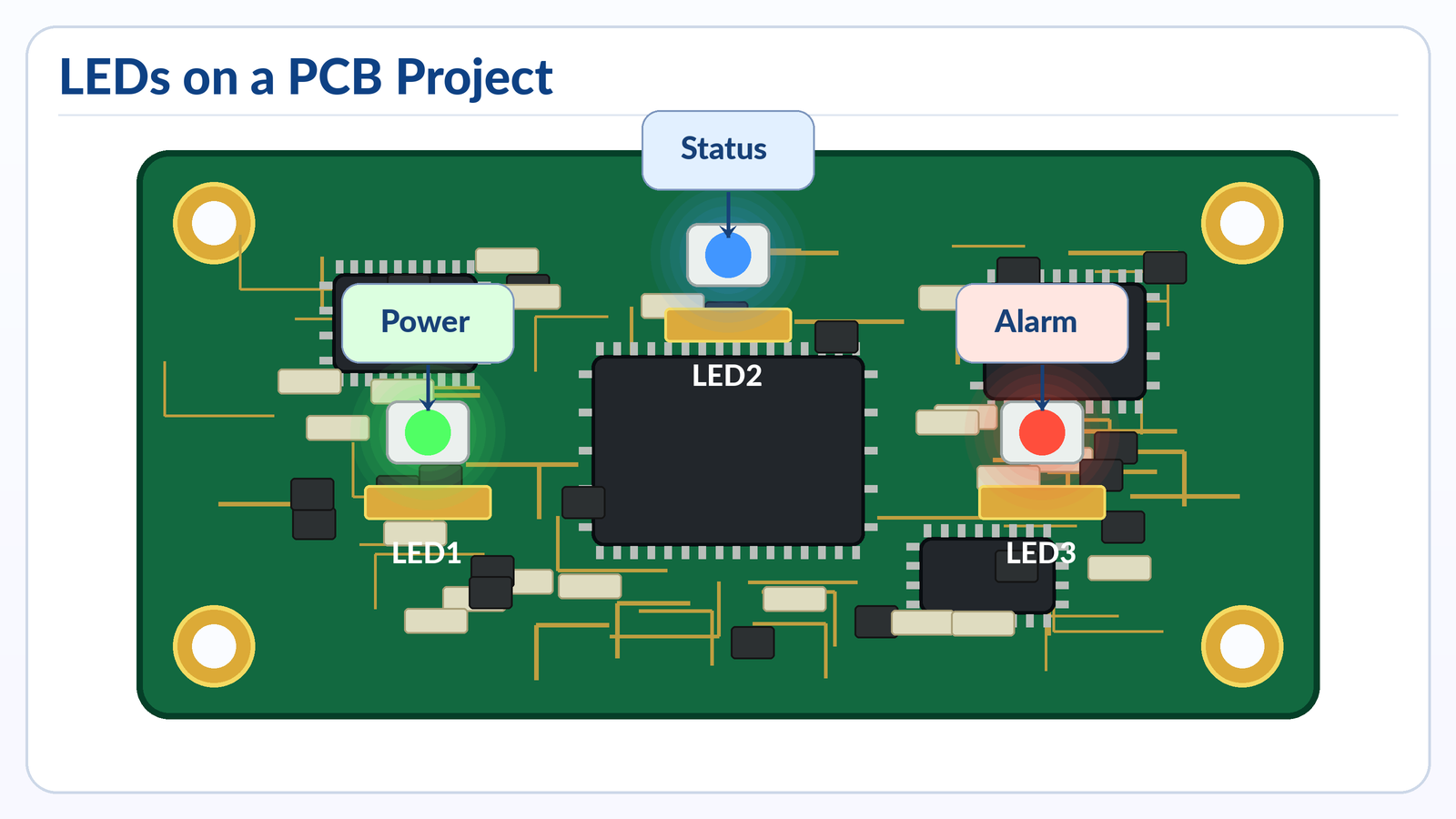
In real projects, the LED symbol appears in many more places than simple breadboard circuits. It is used in consumer electronics, medical devices, industrial controllers, automotive dashboards, communication equipment, power supplies, IoT products, LED lighting, and test fixtures.
Typical LED use cases include:
| Application | LED Function | PCB Design Concern |
|---|---|---|
| Power supply board | Power-on indicator | Resistor value, visibility, polarity |
| Industrial controller | Status signal | Label clarity, EMI environment, serviceability |
| Medical device PCBA | Alarm or state indication | Reliability, color consistency, inspection |
| Automotive switch panel | Backlight or indicator | Temperature, vibration, lifetime |
| LED lighting board | Main light source | Thermal path, current control, material choice |
| Communication equipment | Port status LED | Placement accuracy, light pipe alignment |
| Test fixture | Debug indicator | Easy probing and replacement |
In a prototype, an LED is often used as a quick debugging tool. Engineers may add LEDs to show power rails, MCU status, communication activity, charging state, or fault conditions. In production, those LEDs must be reviewed carefully. Debug LEDs may increase cost, power consumption, assembly time, or light leakage. Some are removed before mass production, while others are kept for service diagnostics.
For PCB buyers, LED-related details should be included in the quotation package when they affect assembly. The Gerber file alone may show pads and silkscreen, but it does not confirm the exact LED color, brightness, viewing angle, polarity mark, packaging reel direction, or test requirements.
How to Prepare LED PCB Files for Manufacturing
For LED PCB or PCBA production, clear files reduce quotation delays and assembly risk. The manufacturer should not need to guess LED polarity from a blurry image or incomplete BOM.
A strong file package should include:
- Gerber files
- Drill files
- BOM with manufacturer part numbers
- Pick-and-place file
- Assembly drawing
- Schematic PDF
- LED datasheets
- Polarity notes for SMD LEDs
- Test requirements
- Lighting performance requirements, if applicable
For LED lighting projects, also provide thermal requirements such as input power, LED current, operating temperature, target lifetime, board material, copper thickness, and heat sink information. For indicator LED projects, provide color, package size, brightness range, and lens or enclosure alignment requirements.
Best Technology supports standard FR4 PCB, multilayer PCB, metal core PCB, ceramic PCB, flexible and rigid-flex PCB, high-frequency PCB, PCB assembly, and component sourcing. The company also lists quality certifications including IATF 16949, ISO 9001:2015, ISO 13485:2016, AS9100D, REACH, RoHS, and UL.
FAQs
What Does the LED Symbol Look Like?
The LED symbol looks like a diode symbol with two small arrows pointing outward. The diode part shows one-way current flow, and the arrows show light emission. The vertical bar side is the cathode, while the other side is the anode. This symbol is used in schematics to separate LEDs from standard diodes, Zener diodes, and photodiodes.
What Does LED Mean in Electronics?
LED means Light Emitting Diode. It is a semiconductor component that emits light when current flows through it in the forward direction. Because it is a diode, it has polarity. The positive side is called the anode, and the negative side is called the cathode. It is widely used for indicators, displays, backlighting, and lighting systems.
Is the Arrow on an LED Symbol the Current Direction?
The diode body in the LED symbol shows the normal forward direction from anode to cathode for conventional current. The two small arrows pointing away from the symbol do not show current direction. They show emitted light. This is an important distinction because beginners sometimes read the light arrows as electrical direction, which can lead to wrong polarity decisions.
Which Side Is Negative on an LED Symbol?
The negative side of an LED symbol is the cathode. In the standard symbol, the cathode is the side with the vertical bar. On a PCB, the cathode may be marked with a bar, “K,” flat side, dot, or package mark. For mass production, always check the LED datasheet and the PCB footprint pin mapping.
Does the Flat Side of an LED Mean Negative?
For many round through-hole LEDs, the flat side of the plastic body marks the negative side, or cathode. The shorter lead also usually marks the cathode. However, this rule should be used with care for special LEDs, trimmed leads, and SMD packages. For production, the datasheet is more reliable than visual inspection alone.
Can an LED Work Without a Resistor?
An LED should not be connected directly to a voltage source unless the circuit already includes current control. A resistor or LED driver is normally used to limit current. Without current limiting, the LED may draw too much current and fail. The resistor value depends on supply voltage, LED forward voltage, and target current.
Why Does My LED Not Light on the PCB?
The LED may not light because it is reversed, the resistor value is too high, the supply voltage is missing, the solder joint is poor, the LED is damaged, or the wrong part was assembled. Start by checking polarity, forward voltage, current path, and solder quality. Then compare the schematic, PCB footprint, BOM, and datasheet.
How Do I Test LED Polarity With a Multimeter?
Set the multimeter to diode mode. Touch the red probe to one LED lead and the black probe to the other. If the LED glows faintly or shows a forward voltage reading, the red probe is on the anode and the black probe is on the cathode. If it does not respond, reverse the probes and test again.
Is LED an AC or DC Component?
An LED is normally driven by DC current in the forward direction. It can be used in AC circuits only with proper protection, rectification, or current limiting. Direct reverse voltage from AC can damage an LED if it exceeds the rated limit. LED lamps for AC mains include driver circuits, not just bare LEDs.
What Is the Difference Between Anode and Cathode in an LED?
The anode is the positive side of the LED during normal forward operation. The cathode is the negative side. Current flows from anode to cathode, and the LED emits light when the forward voltage and current are suitable. On the schematic symbol, the cathode is usually shown by the vertical bar.
Why Are LED Symbols Printed on PCB Silkscreen?
LED symbols or polarity marks are printed on PCB silkscreen to guide assembly and inspection. Since LEDs are polarized, the assembler must know which pad is anode and which pad is cathode. Clear silkscreen helps prevent reversed placement, especially during manual soldering, prototype builds, rework, and first article inspection.
Are All SMD LED Polarity Marks the Same?
No. SMD LED polarity marks vary by manufacturer and package. Some marks indicate the cathode, while others may indicate the anode or pin 1. The mark may be a dot, line, notch, bevel, or colored area. For SMT production, the datasheet and confirmed pick-and-place orientation are essential.
What Does K Mean on an LED PCB Footprint?
“K” usually means cathode. It comes from the German word “Kathode.” If a PCB footprint has a “K” mark beside one pad, that pad should connect to the negative side of the LED in normal operation. Even so, it is good practice to compare the footprint with the schematic and LED datasheet.
Can a Reversed LED Damage a Circuit?
A reversed LED often just stays off in low-voltage circuits. However, if the reverse voltage is too high or the circuit has poor current protection, the LED can fail. In LED strings, one reversed LED can stop the entire string from lighting. In finished products, reversed LEDs usually cause functional test failure.
What Should I Send to a PCB Manufacturer for LED Assembly?
Send Gerber files, BOM, pick-and-place file, assembly drawing, schematic PDF, LED datasheets, polarity notes, and test requirements. For high-power LED boards, also provide current, power, thermal requirements, board material preference, copper thickness, and operating environment. Clear documentation helps reduce assembly errors and quotation delays.
Conclusion
The LED symbol is simple, but its manufacturing meaning is important. It shows a polarized light-emitting diode, with the anode as the positive side and the cathode as the bar side. On a PCB, that symbol must match the footprint, silkscreen, BOM, datasheet, and placement file.
For design and purchasing teams, the safest approach is to treat LED polarity as a controlled assembly detail, not a visual guess. Check the schematic-to-footprint mapping, confirm SMD polarity marks, use current limiting, and include LED function testing when the product depends on visible status or lighting performance.
If you’re sourcing reliable PCB/PCBA manufacturing — OEM, ODM, prototyping, mass production, or custom engineering solutions — reach out to our engineering team for technical support and a quote at sales@bestpcbs.com.