PCB manufacturing PCB manufacturing
Home > Blog

Automotive IR Illuminator Aluminum PCB for In-Cabin Sensing Systems

August 20th, 2026

An automotive IR illuminator aluminum PCB carries current to infrared emitters, provides a stable mounting platform and transfers heat away from the LED array in driver monitoring and other in-cabin sensing systems. The PCB design has to work with the IR emitter package, current profile, camera field of view, beam pattern and module geometry.

Are you worried about these automotive IR illumination problems?

  • The IR LED array runs too hot during pulsed or continuous operation.
  • The camera sees uneven IR illumination, with bright and weak areas across the field of view.
  • The prototype works, but LED position, PCB construction or assembly quality becomes difficult to keep consistent in production.

As a professional one-stop PCB and PCBA service provider, EBest Circuit supports automotive IR illuminator aluminum PCB fabrication, component sourcing, PCB assembly, prototyping and mass production. Our solutions include:

  • Control Current and Heat Around the Emitters
    Match copper geometry, thermal dielectric and metal-core construction to the actual LED current and emitter layout.
  • Maintain Optical and Mechanical Alignment
    Control LED position, orientation, PCB dimensions and mounting features so the illuminator fits the camera module as designed.
  • Carry the Approved Build Into Production
    Keep the validated PCB construction and assembly requirements consistent when moving from prototypes to volume manufacturing.

For an automotive camera illumination aluminum PCB or in-cabin sensing IR aluminum PCB, send your Gerber files, IR LED datasheet and project requirements to sales@bestpcbs.com for a quotation.

Automotive IR Illuminator Aluminum PCB, https://www.bestpcbs.com/blog/2026/08/automotive-ir-illuminator-aluminum-pcb/

What Is an Automotive IR Illuminator Aluminum PCB and Where Is It Used in In-Cabin Sensing?

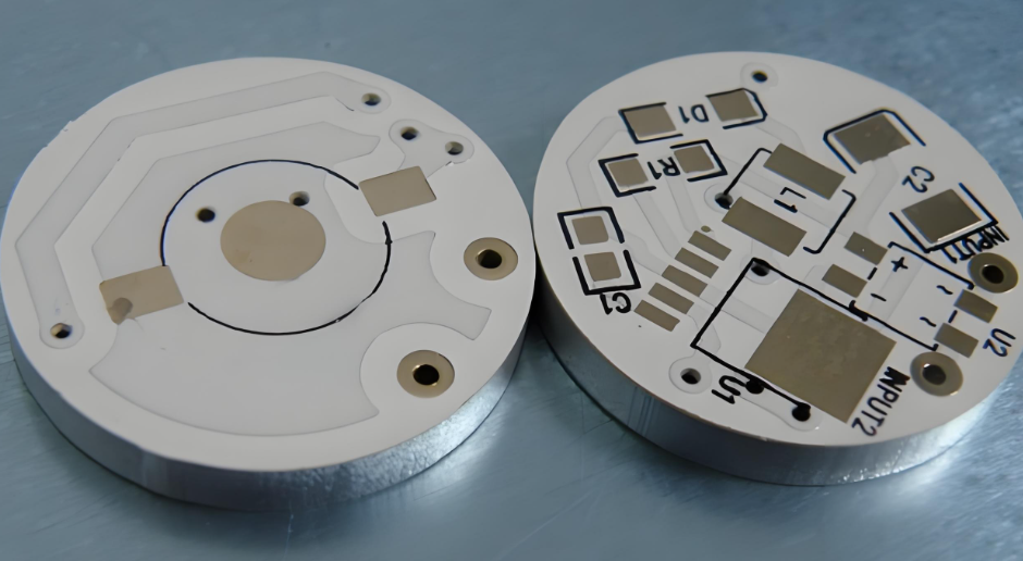
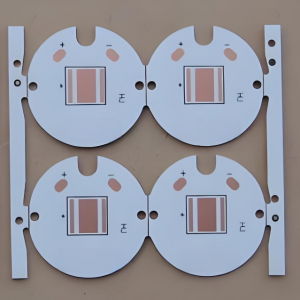
An automotive IR illuminator aluminum PCB is a metal-based PCB used to mount and power infrared LEDs in automotive camera and in-cabin sensing modules. Its main functions are to carry LED current, hold the emitters in the required positions and transfer heat away from the IR LED array.

The board is part of the sensing module rather than a stand-alone lighting circuit. IR LED position, beam direction, camera location and housing geometry all affect how the illuminator performs after installation.

Depending on the optical design, the module may use 850 nm or 940 nm IR emitters.

Typical applications include:

  • Driver Monitoring Systems (DMS): Supports imaging of the driver’s face, eyes and head position.
  • Occupant Monitoring Systems (OMS): Provides IR illumination across passenger and seating areas.
  • Child Presence Detection: Supports camera-based sensing in low visible-light conditions.
  • Interior and Gesture Monitoring: Used in overhead consoles, displays and interior camera modules.
  • Eye-Tracking Systems: Provides controlled illumination around the driver’s eyes and facial area.
Automotive IR Illuminator Aluminum PCB, https://www.bestpcbs.com/blog/2026/08/automotive-ir-illuminator-aluminum-pcb/

How Should an In-Cabin Sensing IR Aluminum PCB Handle LED Current and Heat?

An in-cabin sensing IR aluminum PCB needs to be designed around the actual LED current waveform, particularly when the emitters operate in pulsed or strobed modes.

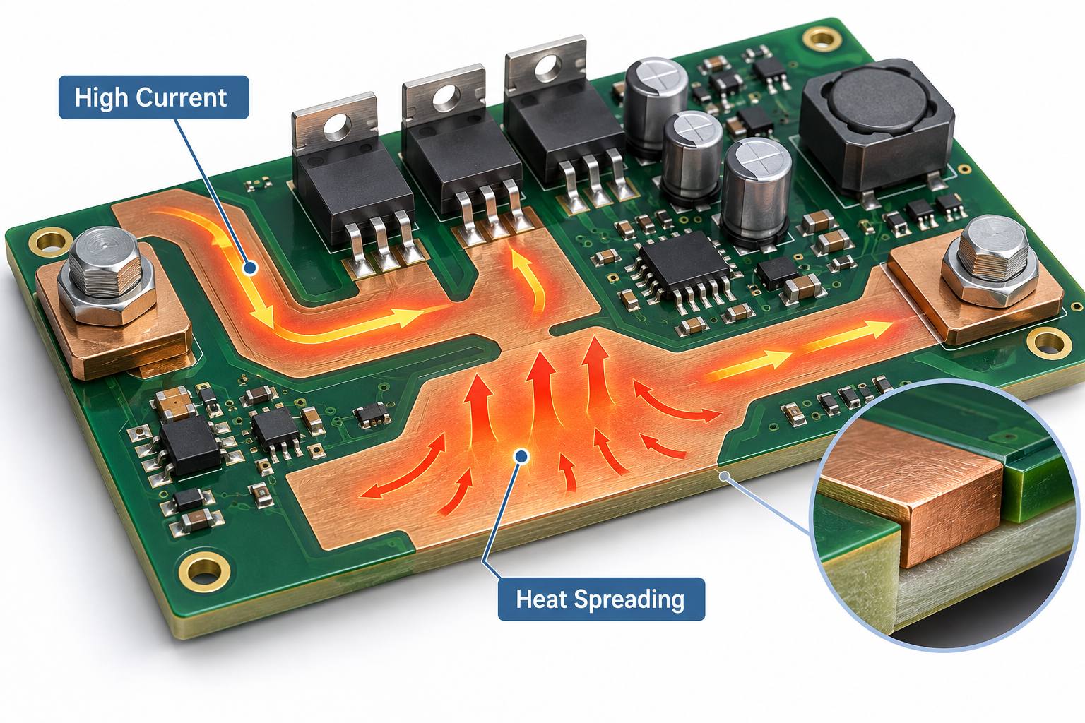
Average current alone does not describe the load on the PCB. During a high-current pulse, the traces, pads, connectors and solder joints may carry a much higher instantaneous current.

  • Size Current Paths for Peak Current
    Use the actual pulse current when setting trace width and copper area. Narrow conductors increase resistance, voltage drop and localized heating.
  • Keep High-Current Paths Short
    Reduce unnecessary distance between the IR LED driver and emitter array. Shorter paths lower resistive loss and make current delivery easier to control.
  • Provide Enough Copper Around the Emitters
    Adequate copper supports current carrying and helps spread heat away from concentrated emitter areas.
  • Avoid Excessive Emitter Clustering
    Several high-current IR LEDs placed in a small area can create a localized thermal load. Their spacing needs to work for both optical coverage and heat distribution.
  • Include Driver Losses When the Driver Shares the PCB
    If the driver is mounted on the same automotive IR LED PCB, its losses become part of the total thermal load.
  • Define the Pulse Profile
    Provide peak current, pulse width and duty cycle during PCB review. These values describe the operating condition more accurately than a single nominal wattage.

How Should Automotive IR LED PCB Layout Support Camera Alignment and Uniform Illumination?

An automotive IR LED PCB layout needs to match the camera field of view and the required illuminated area. LED position, spacing, orientation and beam direction can all affect the image captured by the camera.

  • Match the IR Beam to the Camera Field of View
    A narrow beam may leave weak areas near the edges of the image. A beam that is too wide sends part of the IR output outside the useful sensing region.
  • Control IR LED Orientation
    Directional or asymmetric emitters need the correct rotation on the PCB. A component can be electrically correct and still illuminate the wrong area.
  • Distribute Emitters Across the Required Region
    Poor spacing can create excessive intensity in one area while leaving other parts of the camera image under-illuminated.
  • Use Stable Mechanical References
    Mounting holes, board edges and locating features need to match the camera or illuminator housing so the same optical alignment can be reproduced during assembly.
  • Keep the Optical Path Clear
    Screws, connectors, shields and tall components should not interfere with the IR beam.
  • Include Secondary Optics in the Mechanical Layout
    When the module uses lenses, light guides, diffusers or optical windows, their position and tolerances need to be coordinated with the PCB.

How Should Temperature, Vibration and Long Operating Cycles Affect Automotive IR PCB Design?

Automotive IR modules can experience repeated temperature changes, vibration and high-current emitter pulsing. These conditions affect solder joints, mounting features and the long-term stability of the PCB assembly.

  • Operating Temperature
    PCB materials, solder mask, surface finish and assembly materials need to suit the intended module environment.
  • Thermal Cycling
    Repeated heating and cooling places mechanical stress on solder joints and interfaces around high-current emitters.
  • PCB Mechanical Support
    Large connectors and unsupported board sections should not transfer unnecessary mechanical load to the IR LED solder joints.
  • Mounting-Hole Accuracy
    The PCB should fit the housing without being forced or bent during installation. Poor hole positioning can introduce mechanical stress into the finished module.
  • Component Retention
    Larger components and connectors may require additional mechanical support where vibration is expected.
  • Repeated Pulsed Operation
    High-current strobing creates recurring electrical and thermal loading. The current path and solder joints need to remain stable under the intended operating profile.

What Steps Are Used to Manufacture and Assemble an Automotive IR Illuminator Aluminum PCB?

An automotive IR illuminator aluminum PCB requires controlled fabrication and assembly so the emitter positions, current paths and approved metal-core construction remain consistent.

Step 1: Review the Design and IR LED Requirements

Check the IR LED part number, wavelength, footprint, polarity, orientation, peak current, copper weight, PCB thickness, thermal dielectric, mounting features and surface finish before production starts.

Step 2: Prepare the Metal-Core Laminate

Use the approved copper, dielectric and aluminum construction. A material change can affect thermal performance, finished thickness and mechanical fit.

Step 3: Form the Copper Circuit

Image and etch the IR LED pads, high-current paths and supporting circuitry. Trace width and spacing need to remain compatible with the selected copper weight.

Step 4: Drill and Profile the PCB

Produce mounting holes, slots and the finished board outline from the mechanical drawing. These features may directly control the position of the illuminator inside the camera housing.

Step 5: Apply Solder Mask and Surface Finish

Keep IR LED pads and other solderable areas correctly exposed. The selected surface finish needs to suit the component package and assembly process.

Step 6: Print Solder Paste

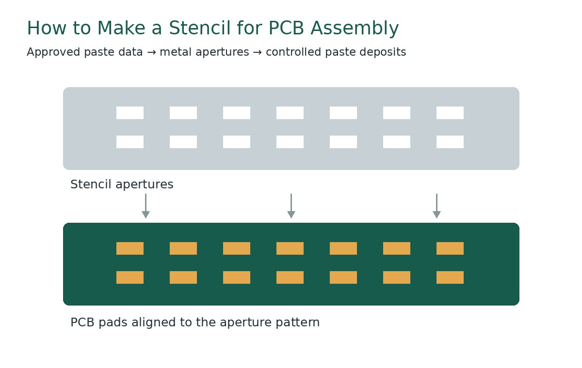
Match stencil openings and solder-paste volume to the IR LED package. Poor paste control can lead to uneven package seating after reflow.

Step 7: Place the IR LEDs

Control X/Y location and component rotation. Placement accuracy is especially important for directional or asymmetric emitters.

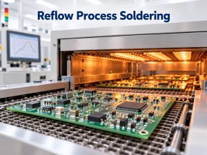
Step 8: Complete Reflow Soldering

Use a reflow profile suitable for the selected components. After soldering, check for poor wetting, package tilt, insufficient solder and other visible defects.

Step 9: Verify the Finished Assembly

Check IR LED polarity, electrical operation, current behavior and mechanical fit before the assembly moves to the next production stage.

Automotive IR Illuminator Aluminum PCB Manufacturing, https://www.bestpcbs.com/blog/2026/08/automotive-ir-illuminator-aluminum-pcb/

What Steps Are Used to Inspect and Test Automotive IR Illuminator PCBs?

Inspection should concentrate on the characteristics that can affect current delivery, IR LED alignment, thermal transfer and final module operation.

Step 1: Verify PCB Construction

Check the aluminum base, thermal dielectric, copper thickness and finished PCB thickness against the approved build.

Step 2: Check Critical Dimensions

Inspect the board outline, mounting holes, slots and locating features used to position the illuminator inside the module.

Step 3: Inspect Circuit and Surface Quality

Use visual inspection and AOI where applicable to identify opens, shorts, damaged pads, contamination and solder-mask defects.

Step 4: Perform Electrical and Insulation Testing

Verify circuit continuity and electrical isolation between the conductive circuit and metal base.

Step 5: Verify IR LED Placement

Check the emitter part number, polarity, X/Y position and rotation against the approved assembly data.

Step 6: Inspect Solder Joints

Review solder wetting and package seating. A tilted IR emitter can affect both heat transfer and beam direction.

Step 7: Perform Functional Current Testing

Operate the assembly under the defined electrical conditions and check LED switching, current delivery and supporting circuit operation.

Step 8: Check Thermal Performance

For higher-current arrays, test the PCB under representative operating conditions. Pulsed designs need an appropriate peak current and duty cycle during validation.

Step 9: Verify Optical Output When Required

When the project includes optical acceptance criteria, test the illuminator using the specified camera, IR sensor or optical fixture rather than relying on visual inspection.

Automotive IR Illuminator Aluminum PCB Testing, https://www.bestpcbs.com/blog/2026/08/automotive-ir-illuminator-aluminum-pcb/

What Automotive IR Aluminum PCB Manufacturing Capabilities Can We Provide?

The table below summarizes our main MCPCB manufacturing capabilities for automotive IR illuminator PCB projects.

ItemCapabilities
Maximum Layer CountUp to 10 layers
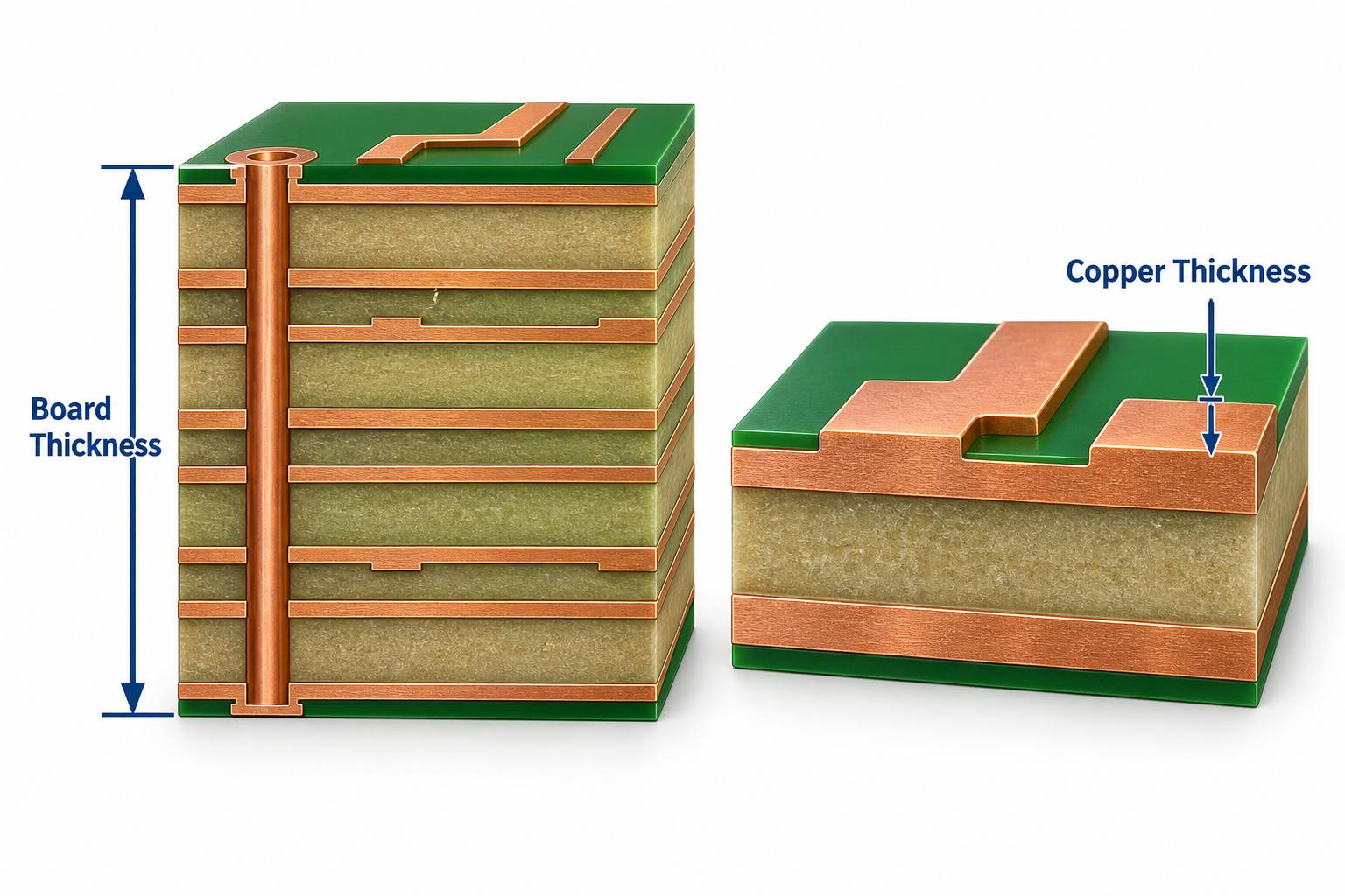
PCB Thickness0.3–4.0 mm
Maximum Board SizeUp to 610 × 1220 mm (24 × 48 in.)
Copper Weight0.5–10 oz
Minimum Trace / Space0.15 / 0.15 mm (6 / 6 mil)
Minimum Hole Diameter0.30 mm (12 mil)
Minimum Punch Hole Diameter3.0 mm (0.12 in.)
Minimum Hole Spacing0.40 mm (16 mil)
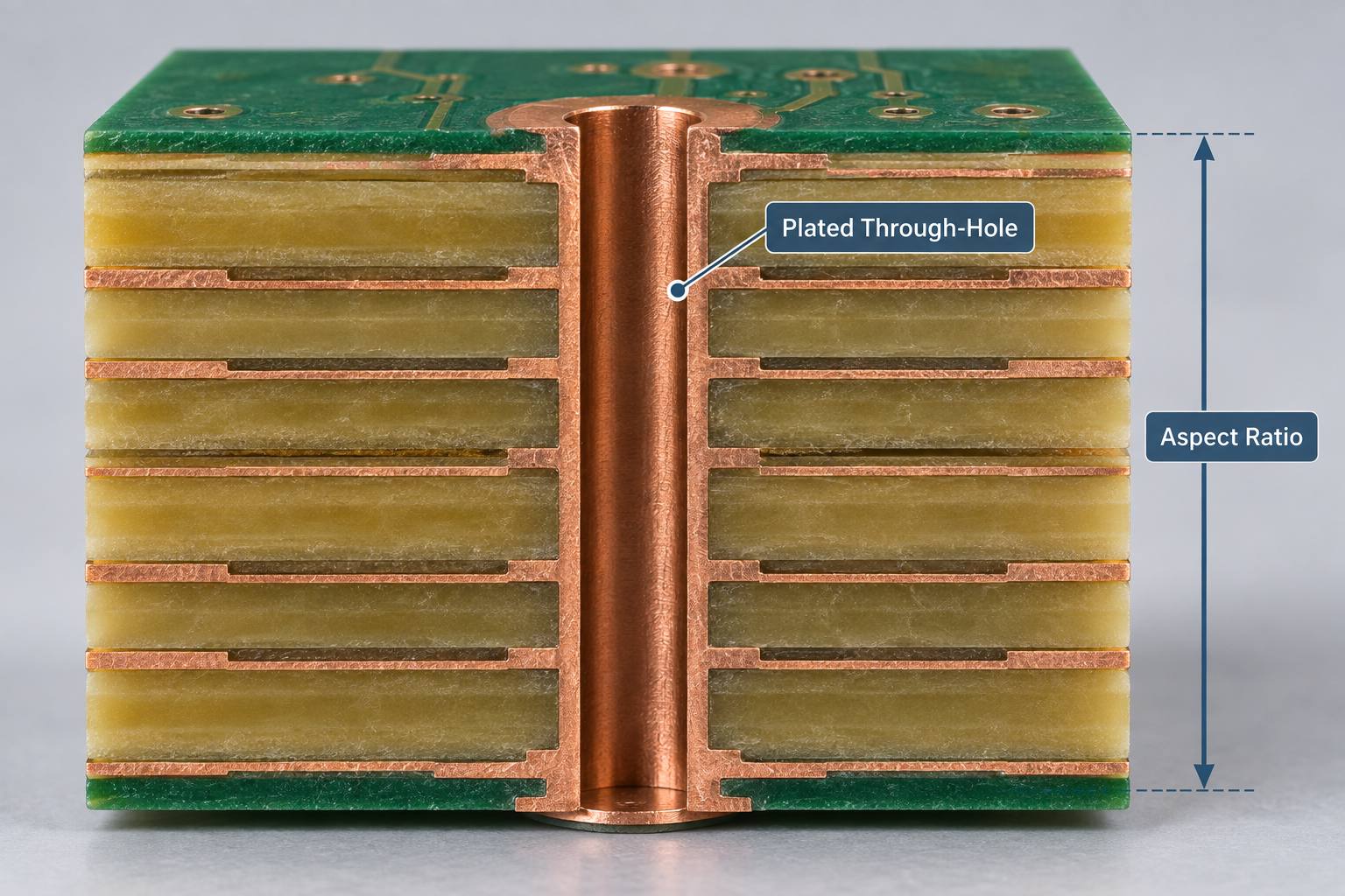
Maximum Aspect Ratio12:1
Minimum Solder Pad Diameter0.40 mm (16 mil)
Thermal Conductivity0.8–1.5 W/m·K standard; 2.0–6.0 W/m·K high thermal conductivity
Warp and Twist< 0.75%
FlammabilityUL 94V-0
Thermal Stress6 × 10 sec at 288°C
Surface FinishENIG, Flash Gold, Hard Gold, Selective Gold Plating, HASL, Lead-Free HASL, OSP, Immersion Silver, Immersion Tin

Case Study: Automotive IR Illuminator Aluminum PCB From Prototype to Production

Project Background

An in-cabin camera module required a compact automotive IR illuminator aluminum PCB for a high-current IR emitter array. The PCB had to fit the camera-module housing while holding the emitters in the positions defined by the optical design.

Project Requirements

The PCB needed to:

  • Carry the specified pulsed LED current
  • Keep IR emitter position and polarity consistent
  • Transfer heat into the metal substrate
  • Match the camera-module mounting geometry
  • Fit within the available module space
  • Support both prototype validation and repeat production

Our Solution

EBest Circuit reviewed the IR LED datasheet, PCB layout and mechanical drawing before prototype fabrication.

The project focused on:

  • Matching IR LED footprints and package orientation
  • Reviewing copper weight and high-current trace geometry
  • Selecting the required thermal dielectric and aluminum construction
  • Controlling board outline and mounting-hole positions
  • Maintaining IR LED placement accuracy during assembly
  • Checking LED seating and solder joints after reflow
  • Keeping the validated PCB construction unchanged for production

Results

Prototype validation confirmed:

  • Correct IR LED placement and polarity
  • Stable mechanical fit inside the camera module
  • Controlled current paths for the emitter array
  • Consistent heat transfer into the metal base
  • A repeatable PCB and assembly specification for production

What Files and Specifications Are Required for an Automotive IR Illuminator Aluminum PCB Quote?

For an automotive IR illuminator aluminum PCB quote, provide the available PCB files, assembly data and key IR LED requirements.

PCB Fabrication:

  • Gerber files
  • NC drill files
  • Mechanical drawing
  • PCB dimensions and thickness
  • Copper weight
  • Aluminum thickness
  • Thermal conductivity requirement
  • Surface finish
  • Quantity and special tolerances

PCB Assembly:

  • BOM
  • Pick-and-place file
  • Assembly drawing
  • IR LED part number and datasheet
  • Polarity and orientation requirements
  • Functional-test requirements

IR and System Requirements:

  • IR wavelength, such as 850 nm or 940 nm
  • Continuous or pulse current
  • Pulse width and duty cycle
  • Number of IR emitters
  • IR LED beam angle
  • Camera field of view
  • Operating temperature
  • Optical acceptance requirements, if applicable

If some specifications are still open, send the available project files first for review.

Why Choose EBest Circuit for Automotive IR LED PCB Manufacturing?

EBest Circuit has more than 20 years of PCB manufacturing experience and supports projects from prototype fabrication to component sourcing, PCB assembly and mass production. Metal-based PCB / MCPCB is included in our PCB product range.

  • Reduce Supplier Coordination
    Keep PCB prototyping, MCPCB fabrication, component sourcing and PCB assembly within one project instead of managing several separate suppliers. This simplifies communication when the IR LED, PCB and assembly requirements need to be reviewed together.
  • Keep Prototype and Production Builds Consistent
    The approved PCB construction, IR LED orientation and assembly requirements can stay within the same manufacturing route as the project moves from engineering samples to volume production, reducing unnecessary changes between stages.
  • Support Automotive Project Requirements
    EBest Circuit holds IATF 16949, together with ISO 9001:2015, ISO 13485:2016 and AS9100D, providing an established quality-management framework for projects with different industry requirements.
  • Handle Thermal PCB Requirements in One Manufacturing Source
    Because metal-based PCB / MCPCB is part of our PCB manufacturing range, automotive IR illuminator projects can be reviewed and produced without moving the thermal PCB portion to a separate supplier.
  • Scale From Engineering Samples to Ongoing Production
    EBest Circuit has approximately 260,000 sq. ft. (28,900 mÂČ) of monthly PCB manufacturing capability and completes more than 1,000 different boards, supporting both prototype programs and continuing production demand.
  • Shorten Lead Time for Eligible Urgent Builds
    Expedited service is available for qualifying projects, with eligible urgent boards capable of shipment within 24 hours. Final lead time depends on the PCB construction and project requirements.

For an automotive IR illuminator aluminum PCB used in DMS, OMS or another in-cabin sensing system, send your Gerber files, BOM, IR LED datasheet and mechanical drawing to sales@bestpcbs.com for a quotation.

FAQs About Automotive IR Illuminator Aluminum PCBs

Q1: Should high-power automotive IR LEDs use a constant-current driver?
A1: In most high-power designs, yes. Controlled current provides more predictable emitter output and prevents excessive LED current. The operating point should follow the selected IR LED and driver specifications.

Q2: Why are IR LEDs often operated in pulsed mode in DMS modules?
A2: Pulsed operation allows the illumination period to be coordinated with camera exposure while reducing average power compared with continuous operation. The PCB still needs to carry the full peak current during every pulse.

Q3: Is 940 nm completely invisible inside the vehicle?
A3: Not under every operating condition. 940 nm generally produces less visible red glow than 850 nm, which is one reason it is commonly considered for in-cabin sensing.

Q4: Can one IR illuminator PCB be used for both DMS and OMS?
A4: Yes, if the optical design covers both sensing regions. Emitter position, beam angle and camera field of view need to be designed together, rather than simply increasing the number of IR LEDs.

Q5: Can an IR illuminator aluminum PCB include connectors and temperature sensors?
A5: Yes. Connectors, thermistors or other monitoring components can be integrated when routing space and assembly requirements allow. Their location should not interfere with the IR optical path.

Q6: Can FR4 be used for an automotive IR emitter array?
A6: It can be suitable for lower thermal loads. A metal-core PCB becomes more useful when multiple high-current IR emitters concentrate heat in a limited board area.

Q7: Does IR emitter binning matter when sourcing components?
A7: It can. Radiant output, wavelength and electrical characteristics may vary by bin or part specification. If the optical design depends on a defined emitter range, the approved sourcing specification should identify it clearly.

Q8: Can near-infrared output be checked visually during production?
A8: No. Visible appearance is not a reliable measurement of near-infrared radiant output. Use an IR-sensitive camera, photodetector or defined optical test fixture when optical verification is required.

Q9: Should the optical window be included during final illumination testing?
A9: Yes when it is part of the finished optical path. Window material, coating, geometry and position can affect the IR energy reaching the camera or sensing area.

Q10: What information should be controlled after prototype approval?
A10: Keep the approved IR LED part number, package orientation, PCB construction, mechanical references and assembly requirements under revision control so production builds remain consistent with the validated design.

Conclusion

An automotive IR illuminator aluminum PCB has to carry high-current IR emitter loads while keeping LED position, mechanical fit and thermal performance consistent inside the sensing module. Current routing, emitter placement, mounting accuracy and assembly control all influence the final result.

EBest Circuit supports metal-core PCB manufacturing, prototyping, component sourcing, PCB assembly and mass production. For an automotive camera illumination aluminum PCB, in-cabin sensing IR aluminum PCB or automotive IR LED module, send your project files and requirements to sales@bestpcbs.com for a quotation.

You may also like

Top 10 Aluminum PCB Manufacturers in China (2026)

August 20th, 2026

Finding an aluminum PCB manufacturer in China is not difficult. The harder part is finding one whose material options, copper capability, thermal design support, mechanical tolerances, production model, and PCB assembly services actually match your project. A factory that is ideal for a standardized LED prototype may not be the right choice for a thick-copper power board, a multilayer aluminum PCB, or an OEM project moving directly into PCBA production.

This guide compares ten aluminum PCB manufacturers in China from a practical engineering and sourcing perspective. Rather than looking only at company size, the comparison focuses on what each supplier is better suited to manufacture and what you should check before releasing Gerber files or selecting a long-term production partner.

aluminum PCB manufacturer

How We Selected the Top Aluminum PCB Manufacturers in China

A manufacturer should offer more than a page saying that aluminum PCBs are available. The useful differences appear in actual materials, board structures, manufacturing limits, engineering support, quality control, and the ability to move from prototype into repeat production.

The manufacturers below were considered around several practical factors:

  • Aluminum PCB manufacturing experience
  • Available board structures and materials
  • Prototype and production support
  • Engineering and DFM support
  • PCB assembly capability
  • Quality and process control
  • Support for international projects

No single supplier is the best fit for every aluminum circuit board. The right choice depends on where your design is most demanding.

Top 10 Aluminum PCB Manufacturers in China

The table below provides a quick shortlist before looking at each supplier in more detail.

No.ManufacturerBest For
1PCBWayOnline prototyping
2JLCPCBStandard low-cost builds
3ALLPCBOnline PCB + PCBA
4EBest CircuitCustom thermal PCB + PCBA
5PCBasicPrototype to production
6Viasion TechnologyLow-/mid-volume builds
7RayMing TechnologyCustom PCB + assembly
8Hitech CircuitsLED / thermal PCB
9Venture ElectronicsMultilayer metal-core PCB
10WellPCBPCB + assembly

1. PCBWay

  • PCBWay is a widely used China-based PCB manufacturing platform with a dedicated aluminum PCB service alongside rigid, flex, rigid-flex, HDI, heavy-copper, metal-core, and other PCB technologies. Its online quotation model makes it particularly accessible during prototype development, where engineers want to upload files, select manufacturing parameters, and move quickly into a small build.
  • The company also publishes information on different aluminum PCB structures, including multilayer constructions, rather than limiting the service to conventional one-layer LED boards. PCB assembly is available when the project needs to move beyond bare-board fabrication.

Best for: Engineers who prefer an online ordering workflow and need flexible prototype or custom PCB options.

2. JLCPCB

  • JLCPCB is particularly attractive when the aluminum PCB fits a standardized manufacturing window. Its current metal-core PCB service includes aluminum- and copper-core options, while the published PCB capabilities identify one-layer aluminum-core boards as a supported material category.
  • That clear process boundary is useful for straightforward prototypes. Engineers can determine early whether the board fits the available material and fabrication options instead of spending time on an open-ended RFQ.
  • For more unusual structures, however, a supplier with a more engineering-led quotation process may be preferable.

Best for: Standardized aluminum PCB prototypes where online ordering and cost control are priorities.

3. ALLPCB

  • ALLPCB combines online PCB manufacturing with component sourcing and PCB assembly. Its current aluminum PCB capability covers 1–2 layers, multiple copper weights, several board thicknesses, and different thermal-conductivity options. The same platform also supports SMT, THT, inspection, X-ray, programming, and functional testing.
  • This makes ALLPCB relevant to buyers who want the convenience of an online sourcing model without necessarily stopping at the bare board.
  • The published process range is also useful for initial screening because engineers can compare their stackup and copper requirements against defined limits before ordering.

Best for: Online aluminum PCB sourcing with downstream PCB assembly requirements.

4. EBest Circuit

  • EBest Circuit has specialized in metal-core PCB manufacturing since 2006, covering aluminum PCB, copper-base PCB, COB MCPCB, thermoelectric-separation structures, prototype builds, volume production, and PCB assembly. Its product range includes single-layer, double-sided, multilayer, and other customized metal-base constructions.
  • The manufacturing model is more suitable for projects that require engineering discussion than for designs that fit a fixed online template. Thermal material, copper weight, mechanical dimensions, dielectric construction, drilling, routing, and assembly requirements can be reviewed together before production.
  • PCB fabrication can also be connected with component sourcing, SMT/THT assembly, inspection, and testing, reducing handoffs when the project is moving toward a finished PCBA.

Best for: Custom aluminum PCB projects that require engineering review and PCB + PCBA manufacturing under one supplier.

5. PCBasic

  • PCBasic provides aluminum PCB fabrication as part of a wider PCB and PCBA manufacturing portfolio. Its published services cover aluminum and metal-core PCBs as well as PCB prototyping, low-volume production, component sourcing, SMT/THT assembly, and functional testing.
  • That broader production scope makes it more relevant to product-development teams than a bare-board-only supplier. A design can begin with prototype fabrication and remain with the same supplier when assembly and subsequent production are required.

Best for: Projects expected to move from prototype into assembled production.

6. Viasion Technology

  • Viasion Technology is a Shenzhen PCB manufacturer focused strongly on prototype and low- to medium-volume work. Its aluminum PCB offering includes single-layer, double-sided, and multilayer metal-core structures, together with PCB fabrication, component sourcing, assembly, and testing services.
  • This production model suits projects where engineering communication and flexibility matter more than a fully automated online quotation.
  • Viasion also manufactures other PCB technologies, which can be useful when one electronic product contains an aluminum power board alongside conventional FR4, flex, or other PCB types.

Best for: Low- to medium-volume custom PCB and PCBA projects.

7. RayMing Technology

  • RayMing Technology, commonly known through the RayPCB brand, offers aluminum and metal-core PCB fabrication together with broader PCB manufacturing and turnkey assembly services. Its published metal-core portfolio includes aluminum- and copper-base constructions intended for applications where heat removal is an important part of board design.
  • The company’s broader PCB capability is useful when a product requires more than one board technology. A power stage may use an aluminum core PCB while the controller remains on a standard FR4 or another specialized board.

Best for: Custom electronics projects combining aluminum boards with other PCB technologies.

8. Hitech Circuits

  • Hitech Circuits has a relatively strong visible focus on aluminum PCB and LED PCB manufacturing. The company publishes single-layer, double-layer, and multilayer aluminum PCB capabilities and also provides PCB assembly and component-sourcing services.
  • This background makes it especially relevant to LED lighting and other thermal applications where the metal-base board is not simply an occasional specialty product.
  • Its wider PCB portfolio also includes copper-base, ceramic, HDI, rigid-flex, and high-frequency boards.

Best for: LED lighting and thermal-management PCB projects.

9. Venture Electronics

  • Venture Electronics manufactures aluminum and broader metal-core PCBs in China and has a strong emphasis on LED and thermal-management applications. Its current fabrication information states support for 1–6 layer aluminum PCBs, alongside metal-core materials, PCB design assistance, fabrication, and assembly.
  • That makes Venture worth considering when an aluminum PCB has moved beyond a simple single-layer structure and the engineering team needs more freedom in layer construction or material selection.

Best for: Multilayer aluminum PCB and customized metal-core projects.

10. WellPCB

  • WellPCB provides aluminum PCB and broader metal-core PCB manufacturing together with PCB assembly and testing. Its metal-core offering covers aluminum and copper structures used in areas such as LED lighting, power electronics, and automotive electronics.
  • The company positions its service around full-cycle manufacturing, so it is more relevant when sourcing extends beyond the bare PCB into component placement and finished assembly.

Best for: Metal-core PCB projects that also require assembly and downstream production.

aluminum PCB manufacturer

What Is an Aluminum PCB?

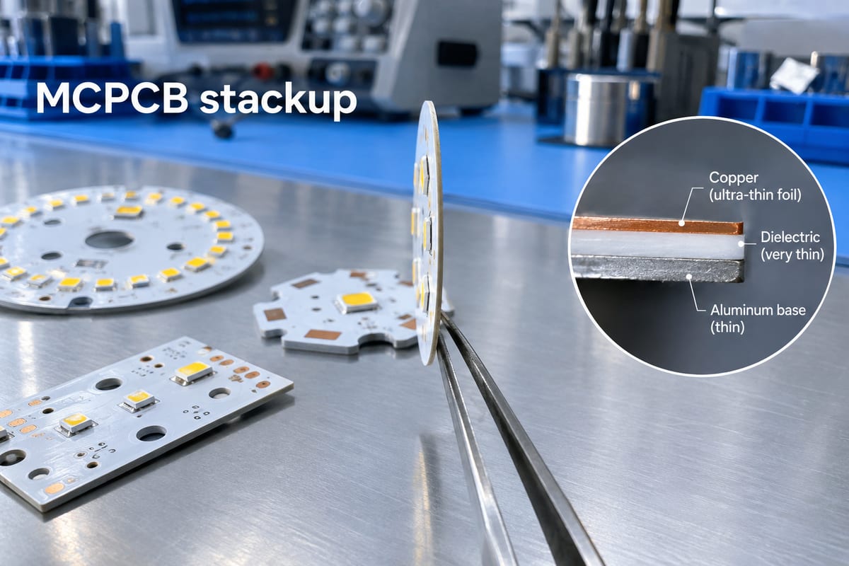
An aluminum PCB is a printed circuit board that uses an aluminum base to spread heat away from components. In a conventional single-sided construction, the main functional layers are:

Copper circuit → thermal dielectric → aluminum base

The copper carries current and forms the circuit pattern. The dielectric beneath it electrically isolates the circuit while conducting heat toward the aluminum substrate. The metal base then spreads that heat over a larger area and toward the housing or heat sink.

This structure is common in LED lighting, power converters, automotive electronics, motor drives, power modules, and other products with concentrated heat sources.

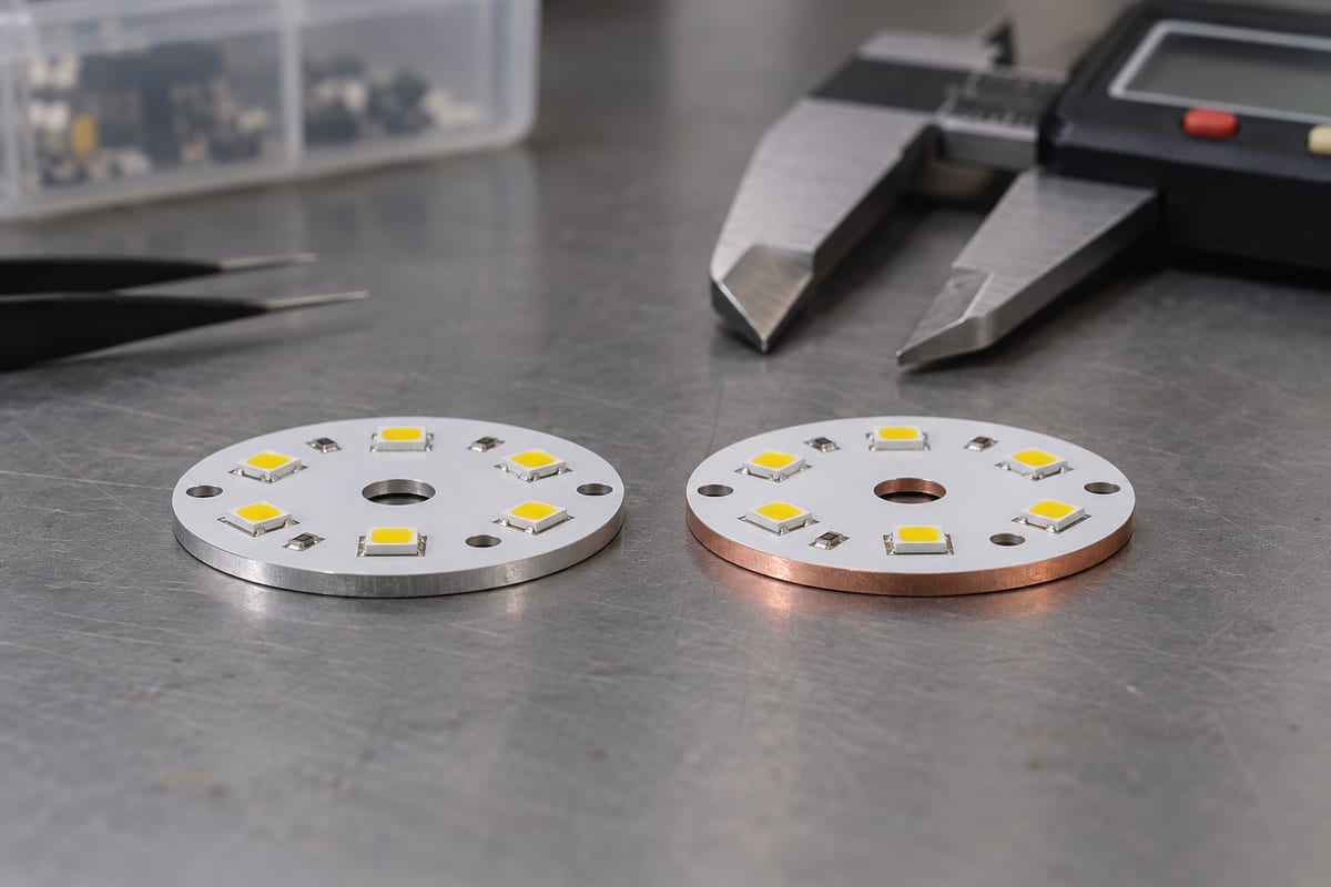
An aluminum PCB is one type of metal core PCB, or MCPCB. These terms are often used together in sourcing, but MCPCB is the broader category: the core or base can also be copper or another metal.

This distinction matters when talking to a metal core PCB manufacturer. A supplier that handles several metal-base structures may have more options when an aluminum substrate cannot meet the project’s thermal or electrical requirements.

aluminum PCB manufacturer

What Aluminum PCB Manufacturing Capabilities Should You Check?

A statement such as “we manufacture aluminum PCBs” tells you very little about whether a supplier can actually build your design.

The useful comparison starts with the parameters that affect the fabrication drawing and stackup:

  • Thermal material
  • Board structure
  • Copper thickness
  • Board thickness
  • Line width and spacing
  • PTH and NPTH capability
  • Board dimensions
  • Routing and slots
  • Outline tolerance
  • V-scoring
  • Surface finish
  • Assembly support

EBest Circuit supports the following aluminum and metal-core PCB manufacturing capabilities:

CapabilityEBest Circuit
Thermal conductivity1–3 W/m·K standard; up to 8 W/m·K
Board structureSingle-, double-sided; selected multilayer
Copper thicknessInner 0.5–3 oz; outer 1–3 oz
Board thickness0.8–3.0 mm standard
Max. size480 × 1180 mm
Min. PTH0.45 mm
Outline tolerance±0.15 mm
Surface finishHASL, OSP, ENIG, Ag, Sn, gold finger

Special materials, heavier copper, tighter tolerances, thicker substrates, and non-standard structures can be reviewed according to the stackup and fabrication drawing.

One parameter should never be judged in isolation. Copper thickness is a good example.

Outer CopperStandard Line / Space
1 oz0.20 / 0.20 mm
2 oz0.25 / 0.25 mm
4 oz0.50 / 0.50 mm

A manufacturer may advertise a very fine minimum trace width, but that figure often applies only to light copper. If your aluminum PCB carries higher current and requires heavier copper, the practical line/space capability changes.

That is why aluminum PCB manufacturing should be reviewed as a combination of material, copper, geometry, mechanical processing, and testing—not as a list of isolated maximum values.

aluminum PCB manufacturer

What Materials Should an Aluminum PCB Manufacturer Offer?

When comparing metal core PCB material, many buyers focus first on the aluminum sheet. In practice, the thermal dielectric deserves at least as much attention.

A conventional aluminum PCB stack contains three main materials:

  • Copper foil — carries current and forms the circuit.
  • Thermal dielectric — transfers heat while maintaining electrical isolation.
  • Aluminum substrate — spreads heat and provides mechanical support.

The dielectric sits directly in the thermal path. Its conductivity, thickness, dielectric strength, adhesion, and temperature behavior can therefore have a major effect on board performance.

This is also why the phrase “3 W/m·K aluminum PCB” does not describe the entire thermal design. Two materials with the same nominal conductivity can have different dielectric thicknesses, insulation characteristics, or thermal resistance.

For a power or thermal design, specify the material system around the actual requirement:

  • Thermal conductivity
  • Dielectric thickness
  • Dielectric strength
  • Copper weight
  • Finished board thickness
  • Operating voltage
  • Mechanical requirements

EBest Circuit’s standard material range includes 1, 2, and 3 W/m·K thermal material classes, while higher-conductivity options from 3 to 8 W/m·K can be evaluated when the application requires them.

Higher thermal conductivity is useful only when it solves an actual thermal bottleneck. A higher headline W/m·K value should not replace a proper review of the complete heat path.

How Do You Verify an Aluminum PCB Manufacturer’s Quality?

A good-looking aluminum circuit board can still have problems that are difficult to see from the surface. Dielectric integrity, copper geometry, hole dimensions, mechanical tolerances, and insulation all matter to finished-board reliability.

A supplier review should therefore cover three areas.

Material control

The factory should be able to identify and trace the aluminum laminate, dielectric system, copper foil, and other critical materials used for the order.

Material substitution matters more than it may appear. A different dielectric can change thermal conductivity, insulation performance, thickness, adhesion, or mechanical behavior even when two finished boards look nearly identical.

Fabrication control

Useful checkpoints for an aluminum PCB include:

  • Copper etching
  • Finished copper thickness
  • PTH and NPTH dimensions
  • Routing and slot dimensions
  • Board outline
  • V-score condition
  • Solder mask
  • Surface finish
  • Electrical continuity
  • Electrical isolation

Mechanical processing also deserves attention because the metal substrate behaves differently from standard FR4 during drilling, routing, and V-scoring.

Quality-system control

The required level depends on the end product. Automotive, industrial, medical, aerospace, and other reliability-sensitive projects may require additional traceability, inspection records, process controls, or specific quality-system certifications.

Certificates are useful, but they are not the entire qualification process. The PCB drawing, material specification, acceptance criteria, inspection plan, and test requirements should agree before production starts.

How Do You Choose the Right Aluminum PCB Manufacturer in China?

Start with the requirement that gives you the least design flexibility. That usually removes unsuitable suppliers faster than comparing website claims or company size.

ProjectCheck First
LED lightingThermal material
Power electronicsDielectric + copper
AutomotiveQuality + traceability
PrototypeEngineering response
Thick copperEtching capability
Complex outlineMechanical tolerance
OEM PCBAPCB + assembly
Volume productionRepeatability

For a standard one-layer aluminum PCB, an online manufacturer can be a very efficient option. If the board fits a published process window for material, thickness, copper, dimensions, and surface finish, there may be little reason to complicate sourcing.

The decision changes when the design includes heavier copper, a non-standard dielectric, unusual PTH or NPTH features, tight mechanical dimensions, multilayer construction, or customer-defined testing.

At that point, engineering communication becomes part of the manufacturing capability.

The same applies when the board will be assembled. Aluminum PCBs often carry LEDs, MOSFETs, power devices, drivers, converters, or other components that generate heat. PCB fabrication is only one part of the final thermal path.

If one supplier handles PCB fabrication and PCBA, the engineering review can also consider component placement, soldering, thermal interfaces, inspection, and functional testing.

For an OEM project, send the same controlled RFQ package to two or three shortlisted aluminum PCB manufacturers. Compare more than the quoted unit price.

Pay attention to the questions each supplier asks.

A manufacturer that checks the dielectric, copper weight, stackup, hole structure, outline, panelization, assembly requirements, and testing is showing you how it approaches manufacturability before the board reaches production.

What Should You Send for an Aluminum PCB Quote?

A Gerber file and quantity may be enough for a very simple board. For a customized aluminum PCB, they leave too much open to interpretation.

For bare-board fabrication, provide:

  • Gerber or ODB++ files
  • Fabrication drawing
  • Board dimensions
  • Layer structure
  • Thermal material requirement
  • Finished copper weight
  • Finished board thickness
  • Surface finish
  • PTH / NPTH requirements
  • Slots and routing details
  • V-score requirements
  • Quantity
  • Inspection or testing requirements

If thermal conductivity is specified, make it clear what the value refers to. The manufacturer should not have to guess whether the requirement applies to the dielectric, laminate system, or another thermal interface.

For PCB assembly, also provide:

  • BOM
  • Pick-and-Place / CPL file
  • Assembly drawing
  • Approved manufacturer list, if applicable
  • Programming files
  • Inspection requirements
  • Functional-test requirements

Complete RFQ data helps the manufacturer identify material or manufacturing conflicts before quotation instead of discovering them after production has already started.

FAQs About Aluminum PCB Manufacturers in China

Is an Aluminum PCB the Same as an MCPCB?

Not exactly. An aluminum PCB is one type of MCPCB. Metal core PCB is the broader term and can include aluminum, copper, or other metal-base structures. Aluminum is common because it offers a practical combination of thermal performance, weight, machinability, and cost.

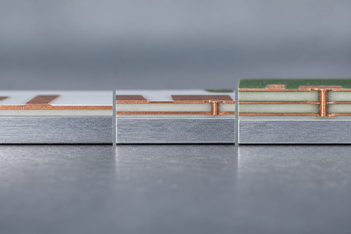
Can Aluminum PCBs Be Multilayer?

Yes. Aluminum PCBs are not limited to simple one-layer LED boards. Several manufacturers offer double-sided or multilayer metal-base structures, although available stackups and fabrication limits vary considerably between suppliers.

What Thermal Conductivity Should I Choose for an Aluminum PCB?

Choose the dielectric according to the actual thermal and electrical requirements rather than automatically selecting the highest W/m·K rating. Dielectric thickness, insulation requirement, copper weight, component losses, board area, and the downstream heat sink all affect the final temperature.

Can an Aluminum PCB Manufacturer Also Provide PCB Assembly?

Yes. Many China-based aluminum PCB manufacturers also provide component sourcing, SMT/THT assembly, inspection, and testing. A combined service can reduce handoffs when the project moves from bare-board fabrication into PCBA production.

When Should I Consider Copper Core Instead of Aluminum?

Copper-base constructions become worth evaluating when heat flux, current density, or the required thermal path exceeds what a conventional aluminum structure can provide efficiently. Copper offers stronger bulk thermal performance, but it also increases material cost and weight, so the change should come from the design requirement rather than material preference.

Need an Aluminum PCB Manufacturer for Your Project? If your project is already moving from design into prototype or production, EBest Circuit can review the aluminum PCB stackup, thermal material, copper weight, mechanical requirements, and manufacturability before fabrication. For PCBA projects, you can also submit the BOM, Pick-and-Place file, assembly drawing, and testing requirements for a combined PCB + assembly review. Send your project files to sales@bestpcbs.com for engineering review and quotation.

You may also like

940nm Automotive IR LED Aluminum PCB for Camera Illumination

August 20th, 2026

A 940nm automotive IR LED aluminum PCB is used in automotive camera illumination systems such as driver monitoring and occupant monitoring, where 940nm IR LEDs provide low-visible-glow illumination for cameras operating in low-light conditions. Its performance depends on camera sensitivity, IR radiant output, pulsed current, thermal resistance, LED placement and optical uniformity, so these factors must be evaluated together during PCB design, assembly and validation.

Are you facing these problems in a 940nm automotive IR LED aluminum PCB project?

  • IR output does not match the camera: The selected 940nm LEDs appear powerful enough, but the camera image is still dark or inconsistent.
  • Temperature rises more than expected: Peak current is acceptable on paper, but repeated pulses create excessive temperature at the LED or PCB.
  • Prototype illumination cannot be repeated easily: LED position, orientation, soldering or component variation changes the illumination pattern between builds.

As a professional one-stop PCB and PCBA service provider, EBest Circuit supports automotive IR LED aluminum PCB fabrication, component sourcing, PCB assembly, prototyping and mass production. Our solutions include:

  • Match illumination to the actual camera: Review sensor response, optical transmission, FOV and emitter characteristics before defining the required IR output.
  • Verify the real pulse load: Peak current must be reviewed together with pulse width, duty cycle, repetition rate and operating temperature.
  • Control what affects production consistency: The released LED part number, footprint, orientation, placement and assembly requirements should remain controlled from prototype through production.

Developing a 940nm automotive IR LED aluminum PCB? Send the PCB files, BOM, IR LED part number and operating conditions to sales@bestpcbs.com for manufacturing review.

940nm automotive IR LED aluminum PCB, https://www.bestpcbs.com/blog/2026/08/940nm-automotive-ir-led-aluminum-pcb/

Why Is a 940nm Automotive IR LED Aluminum PCB Used for Camera Illumination?

A 940nm automotive IR LED aluminum PCB is used when a camera illumination module needs low-visible-glow IR output, pulsed LED operation, heat transfer and controlled emitter positioning. Current 940nm automotive IR LEDs are specifically offered for driver monitoring, occupant monitoring, interior monitoring, gesture sensing and child-presence detection.

  • Reduced visible red glow: 940nm produces substantially less visible red glow than 850nm, which is useful when illumination operates inside a dark vehicle cabin.
  • Low-light camera illumination: 940nm emitters provide near-infrared illumination for camera-based in-cabin sensing when available visible light is insufficient.
  • High-current pulse operation: Automotive IR emitters can be designed for short high-current pulses. The allowable current depends on pulse width, duty cycle and temperature rather than a single current rating.
  • Thermal management: Heat generated at the emitter must pass through the LED package, solder interface and PCB into the mechanical heat-spreading structure.
  • Controlled LED positioning: Automotive 940nm emitters are available with circular, rectangular and tilted radiation patterns, so component position and rotation directly affect the illuminated field.
940nm Automotive IR LED Aluminum PCB, https://www.bestpcbs.com/blog/2026/08/940nm-automotive-ir-led-aluminum-pcb/

How Do Camera Sensitivity and Optical Filters Affect 940nm IR LED Radiant Power?

The required 940nm radiant output depends on how much usable infrared energy reaches the image sensor after losses through the optical system.

  • Sensor sensitivity at 940nm: Higher NIR quantum efficiency increases the camera response for a given amount of incident 940nm energy. Sony’s IMX775 shows that automotive sensors can be specifically optimized for this wavelength.
  • Lens transmission: The lens must transmit sufficient energy around the selected NIR wavelength.
  • Optical filters: IR-pass, band-pass or other filters can attenuate part of the 940nm energy before it reaches the sensor.
  • Protective covers: Dark camera windows or trim materials can introduce additional NIR transmission loss.
  • Working distance: As the illuminated field expands, the same radiant output is distributed over a larger area.
  • Target reflectivity: Skin, fabric and other cabin surfaces do not return the same amount of NIR energy to the camera.
  • Exposure conditions: Camera exposure and synchronization with the LED pulse influence how much reflected IR is captured.
  • Beam pattern: Narrow, wide, rectangular and tilted emitters distribute the available radiant output differently.

Electrical wattage should not be used as an optical-output specification. The SFH 4728BS A01 T1 datasheet separately specifies parameters such as radiant intensity and optical characteristics under defined operating conditions.

How Do Peak Current, Pulse Width and Duty Cycle Define the Load on a 940nm IR LED Aluminum PCB?

Peak current defines only the highest instantaneous current. Pulse width, duty cycle, repetition rate and operating temperature determine how the LED and PCB experience that load over time.

  • Peak current: Maximum current carried during each IR pulse.
  • Pulse width: Duration of the high-current event.
  • Duty cycle: Percentage of time the LED remains energized.
  • Repetition frequency: How frequently the pulse repeats.
  • Forward voltage: Together with current, determines instantaneous electrical input.
  • Simultaneous LED count: Multiple emitters operating together increase total board and connector current.
  • Operating temperature: Permissible pulse current changes as component temperature rises.

The SFH 4728BS A01 T1 specifies 1.5A maximum forward current and up to 5A pulsed forward current only when tp ≀ 10ms and D ≀ 0.25. Its permitted operating current also varies with pulse and thermal conditions.

For a 940nm IR LED aluminum PCB, specify the complete pulse profile rather than only a maximum current value.

How Should Thermal Resistance Be Controlled in a Pulsed 940nm Automotive IR LED Aluminum PCB?

Thermal resistance must be controlled across the complete path from the LED junction to the housing. The aluminum base is only one part of that path.

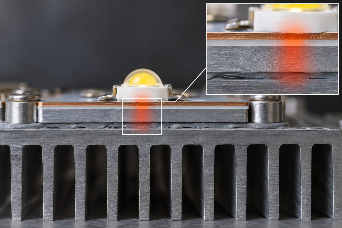
For a conventional single-layer aluminum IMS, the thermal path is typically:

LED junction → package thermal pad → solder joint → copper circuit layer → thermally conductive dielectric → aluminum base → thermal interface/contact → housing or heat spreader

Insulated metal substrates are specifically used to reduce thermal impedance and conduct heat from high-watt-density surface-mount assemblies.

Control the thermal path by:

  • Maintaining the LED thermal pad area: Follow the released package footprint instead of reducing the heat-transfer area for routing convenience.
  • Controlling the solder interface: Poor wetting, insufficient solder or excessive voiding beneath the thermal pad can increase interface thermal resistance.
  • Maintaining the approved PCB construction: The dielectric lies directly in the heat path, so an unapproved change in construction can alter thermal performance.
  • Controlling PCB-to-housing contact: Poor flatness or incomplete mechanical contact adds another thermal interface.
  • Controlling TIM where used: Excessive thickness or trapped air can reduce effective heat transfer.
  • Testing with the actual pulse conditions: Thermal verification should reproduce the specified current, pulse width, duty cycle and ambient condition.

The SFH 4728BS A01 T1 specifies a maximum junction temperature of 145°C and a junction-to-solder-point thermal resistance of 3.9K/W typical and 4.7K/W maximum. These are component values, not the thermal resistance of the complete PCB and housing assembly.

How Should 940nm IR LED Placement and Beam Angle Match the Automotive Camera FOV?

LED placement should provide sufficient illumination across the camera’s horizontal and vertical FOV at the intended working distance.

  • Define the camera FOV: Use the actual horizontal and vertical field that requires illumination.
  • Define the working-distance range: Check coverage at relevant near and far positions.
  • Account for camera-to-LED offset: LEDs positioned beside the camera do not share the same optical axis.
  • Match beam pattern to the field: A rectangular camera field may be better matched by a rectangular IR emitter.
  • Control component orientation: Rectangular and tilted emitters require the correct PCB rotation.
  • Reference LEDs to mechanical datums: LED position should remain aligned with the camera and housing during final assembly.

Current automotive 940nm IR products include 60°, 80°, 150°, 110° × 135° and 130° × 155° beam patterns, together with tilted-emission variants.

The correct beam is the one that covers the required camera FOV with adequate irradiance, not simply the widest available emitter.

How Can a 940nm IR LED Array Reduce Hot Spots and Improve Illumination Uniformity?

Uniform illumination depends on LED spacing, beam overlap, emitter orientation and working distance.

  • Reduce center hot spots: Avoid concentrating the high-intensity centers of several beams in the same area.
  • Improve edge coverage: Review LED position and beam shape when the outer FOV receives insufficient illumination.
  • Prevent dark gaps: Adjacent emitters should provide adequate overlap at the intended working distance.
  • Use asymmetric beams where appropriate: Rectangular or tilted emitters can direct more energy toward areas that a circular beam covers inefficiently.
  • Control LED rotation: Orientation errors can shift rectangular or tilted patterns away from the required field.
  • Balance independent channels where available: Current adjustment can help correct some illumination imbalance, provided each emitter remains inside its specified limits.
  • Measure across the FOV: Optical validation should evaluate several positions across the camera field rather than only the optical center.

Automotive 940nm emitters with 110° × 135° and 130° × 155° rectangular patterns are already available for in-cabin sensing, showing that beam geometry is an application-level design parameter.

Adding more LEDs is not automatically an improvement; poor beam overlap can create stronger hot spots while also increasing current and heat.

What PCB Layout Details Matter for High-Current 940nm Automotive IR LED Arrays?

The PCB layout must carry the pulse current while preserving the LED thermal connection and optical position.

  • Current path: Route for the real peak current and simultaneous LED load, not only average current.
  • Compact pulse loop: Keep driver-to-LED and return paths short to reduce unnecessary resistance and parasitic inductance.
  • Branch consistency: Avoid unnecessary differences in path resistance between comparable LED branches.
  • Exact LED footprint: Use the released manufacturer’s land pattern.
  • Thermal pad connection: Preserve the intended thermal-contact area of the package.
  • Connector path: Include connector and cable resistance when the LED driver is located off-board.
  • Sensitive reference paths: Keep high di/dt LED current away from sensitive sensing or control references.
  • Optical orientation: Tie LED rotation to the camera or housing datum.
  • Temperature sensing: Position temperature sensors where they support the intended thermal-control or protection method.

The SFH 4728BS A01 T1 is supplied with package-specific dimensional and solder-pad requirements, reinforcing the need to design around the exact released emitter rather than a generic high-power LED footprint.

What Manufacturing and Assembly Controls Matter for a 940nm Automotive IR LED Aluminum PCB?

Manufacturing should reproduce the approved PCB construction, IR LED part number and optical geometry from prototype through production.

Step 1: Verify the released project files

Confirm the Gerber or ODB++, BOM, pick-and-place file, assembly drawing, exact IR LED ordering code, polarity, rotation and critical dimensions.

Step 2: Verify the LED footprint

Compare the land pattern with the current LED datasheet. For rectangular or tilted emitters, verify both electrical orientation and optical direction.

Step 3: Manufacture the approved PCB construction

Build according to the released copper, dielectric, aluminum base, surface finish, dimensions and mechanical tolerances. Review any proposed construction change before production.

Step 4: Control solder paste and placement

Control paste deposition, component centering and LED rotation because they affect solder quality, thermal contact and optical position.

Step 5: Follow LED handling and reflow requirements

The selected emitter’s current datasheet should control footprint, handling and reflow requirements. The cited SFH 4728BS family includes defined assembly requirements and package-specific solder information.

Step 6: Inspect the finished assembly

Check LED polarity, orientation, placement, solder condition and electrical operation. Perform thermal or optical verification when those acceptance limits are included in the project specification.

The SFH 4728BS A01 T1 also defines separate radiant-intensity groups, so the approved ordering code or permitted optical group should remain controlled when production uniformity depends on binning.

What Automotive Reliability Requirements Apply to a 940nm IR LED Camera Illumination Board?

Automotive reliability should be separated into component qualification and finished-module validation.

  • IR LED qualification: AEC-Q102 covers failure-mechanism-based stress-test qualification for discrete optoelectronic semiconductors used in automotive applications.
  • Component evidence: The current SFH 4728BS A01 T1 is identified by ams OSRAM as AEC-Q102 qualified.
  • Finished PCB validation: Qualification of the emitter does not qualify the assembled aluminum PCB.
  • Environmental requirements: The final camera illumination assembly may require temperature, cycling, vibration, power-cycling or other validation according to the vehicle program.
  • Traceability: PCB revision, BOM revision, IR LED ordering code and production-lot information should remain controlled when required by the project.

AEC-Q102-qualified LED ≠ AEC-Q102-qualified PCB assembly.

AEC-Q102 applies to the optoelectronic semiconductor component, not the complete 940nm automotive IR LED aluminum PCB.

How Should a 940nm Automotive IR LED Aluminum PCB Be Tested for Electrical, Thermal and Optical Performance?

A finished 940nm automotive IR LED aluminum PCB should be tested under actual or representative camera-module operating conditions.

  • Electrical performance: Check LED polarity, continuity, forward voltage, peak current, pulse width, duty cycle and repetition frequency. Measure the LED pulse waveform where the project requires waveform verification.
  • Thermal performance: Operate the board at the specified peak current, pulse width and duty cycle. Measure temperature at defined locations such as the LED solder area, aluminum base and housing interface. Compare the result with the selected emitter’s temperature limits.
  • Optical output: Where radiant output is specified, measure it using a defined current waveform, working distance and detector position.
  • Camera FOV coverage: Verify illumination across the required horizontal and vertical field, including the edges and corners.
  • Illumination uniformity: Measure IR intensity across multiple positions to identify center hot spots, dark edges and gaps between LED beams.
  • LED-to-LED consistency: For multi-LED arrays, check for abnormal differences caused by current variation, optical binning, component placement or assembly.
  • Board-to-board consistency: Compare representative production boards under the same drive and measurement conditions when optical consistency is part of the acceptance requirement.
  • Camera-level performance: When required, operate the board with the intended camera and verify the defined low-light image performance.
  • Test-condition control: Record ambient temperature, supply voltage, peak current, pulse width, duty cycle, working distance and camera or detector position so test results remain comparable.
  • Photobiological safety where applicable: If the finished IR source requires safety evaluation, IEC 62471 provides exposure limits, measurement methods and classification guidance for electrically powered incoherent optical sources, including LEDs, from 200nm to 3000nm.
940nm Automotive IR LED Aluminum PCB Testing, https://www.bestpcbs.com/blog/2026/08/940nm-automotive-ir-led-aluminum-pcb/

Why Choose EBest Circuit for 940nm Automotive IR LED Aluminum PCB Manufacturing?

For a 940nm automotive IR LED aluminum PCB project, the approved PCB, IR LED and assembly data need to remain consistent from prototype through production. EBest Circuit supports PCB fabrication, component sourcing and PCB assembly within its stated service scope.

  • Reduce coordination between PCB and assembly suppliers: PCB fabrication, component sourcing and PCB assembly can be handled within the same service scope, reducing unnecessary transfers of BOM, PCB revision and assembly information.
  • Keep the specified 940nm IR LED under BOM control: The customer-approved part number can remain tied to the released BOM rather than being treated as a generic 940nm emitter. This matters when beam pattern, package, optical-output group or pulse rating affects the finished module.
  • Carry prototype requirements into production: EBest Circuit supports PCB prototyping and mass production, allowing the approved PCB revision, footprint, orientation and assembly data to remain controlled as the project moves forward.
  • Support automotive manufacturing requirements: EBest Circuit’s supplied company information lists IATF 16949 and ISO 9001:2015 among its certifications.
  • Metal-based PCB manufacturing experience: Metal Core PCB is included in the company’s stated PCB product range, and EBest Circuit was founded in 2006.
  • Project-specific manufacturing review: Gerber or ODB++ files, LED footprint, BOM, placement data and pulse conditions can be reviewed against the released project requirements rather than replaced with generic aluminum PCB recommendations.
940nm Automotive IR LED Aluminum PCB, https://www.bestpcbs.com/blog/2026/08/940nm-automotive-ir-led-aluminum-pcb/

What Files and Specifications Are Required for a 940nm Automotive IR LED Aluminum PCB Quote?

For an initial 940nm automotive IR LED aluminum PCB quote, provide the PCB files, assembly data and actual IR LED operating conditions. Add thermal or optical acceptance requirements when they form part of the manufacturing scope.

PCB Fabrication Files

  • Gerber or ODB++ files
  • NC drill files
  • Fabrication drawing
  • Board dimensions and mechanical drawing
  • Approved PCB construction
  • Copper thickness
  • Surface finish
  • Critical dimensions and tolerances
  • Prototype or production quantity

PCB Assembly Files

  • BOM
  • Pick-and-place file
  • Assembly drawing
  • Exact 940nm IR LED manufacturer and part number
  • LED datasheet
  • Polarity and orientation requirements
  • Approved alternatives, if applicable

IR LED Operating Conditions

  • Supply voltage
  • Peak LED current
  • Pulse width
  • Duty cycle
  • Repetition frequency
  • Number of LEDs operating simultaneously
  • Driver or test-interface information where functional testing is required

Optical and Thermal Requirements

Provide these when applicable:

  • Camera FOV
  • LED beam pattern
  • Working distance
  • Required illumination area
  • LED position or rotation tolerance
  • Radiant-output requirement
  • Illumination-uniformity requirement
  • Thermal test conditions and temperature limits
  • Camera-level functional test criteria

If some specifications are still being finalized, the available Gerber or ODB++ files, BOM, LED part number and pulse conditions are sufficient to begin an initial manufacturing review.

FAQs About 940nm Automotive IR LED Aluminum PCBs

The question topics below were selected from recurring community discussions about 850nm versus 940nm camera compatibility, IR visibility, IR-cut filters, beam coverage and external IR illumination on Reddit and other electronics communities. The technical answers are based on device or standards information rather than community claims.

Q1: Can a camera that works with 850nm IR also work with a 940nm illuminator?

A1: Compatibility depends on the image sensor and complete optical path. A camera may detect both wavelengths but have substantially different sensitivity at each. Before moving from 850nm to 940nm, check the sensor spectral response and filter transmission. Sensors can also be optimized specifically for 940nm; Sony’s IMX775 specifies 35% QE at 940nm.

Q2: Why can the same 940nm illuminator look much brighter on one camera than another?

A2: The result depends on the sensor’s 940nm response, lens and filter transmission, exposure conditions and camera processing. The same IR source can therefore produce different image brightness on different cameras. Evaluate the LED with the intended production camera, not by LED wattage alone.

Q3: Is a 940nm IR LED completely invisible?

A3: It is safer to describe 940nm as having very low visible red glow rather than guaranteeing absolute invisibility. ams OSRAM describes 940nm as virtually invisible with only slight red glow, while community users also report that faint emission can still be noticeable under some dark-viewing conditions.

Q4: Does LED binning matter in a multi-LED 940nm array?

A4: Binning matters when the application requires controlled optical output between LEDs or production boards. The SFH 4728BS A01 T1, for example, is supplied with defined radiant-intensity groups. Control the approved ordering code or permitted bin range when optical consistency is part of the specification.

Q5: Can a narrower 940nm LED beam improve useful illumination distance?

A5: A narrower radiation pattern concentrates more of the available radiant output within a smaller angular field, while a wider pattern distributes it across a larger field. The correct choice should therefore balance irradiance and required camera FOV, not distance alone. Current automotive 940nm products range from relatively narrow patterns to 150° and rectangular 130° × 155° options.

Q6: Can a 940nm IR LED be driven far above its continuous-current rating if the duty cycle is low?

A6: Only within the pulse limits stated in the exact LED datasheet. Permitted peak current depends on pulse width, duty cycle and temperature, not duty cycle alone. The SFH 4728BS A01 T1 permits up to 5A pulsed current only under defined pulse conditions, while its continuous-current limit is lower.

Q7: Can an IR-cut filter prevent a camera from using 940nm illumination?

A7: A camera will receive less 940nm energy if its optical filter has low transmission at that wavelength, even when the image sensor itself has useful NIR sensitivity. This is why the sensor response and optical-filter transmission must be reviewed together before changing the IR wavelength.

Q8: Can one 940nm IR LED be replaced by another 940nm part without changing the PCB or optical design?

A8: The same nominal wavelength does not make two LEDs interchangeable. Parts can differ in package dimensions, solder pad, beam pattern, optical output, thermal resistance and pulse-current limits. ams OSRAM’s current 940nm automotive range alone includes 50°, 60°, 80°, 150°, rectangular and tilted-emission versions.

Q9: Should IR eye safety still be evaluated when 940nm light is difficult to see?

A9: Visible brightness is not a valid measure of infrared exposure. Where photobiological safety assessment is required, the complete source should be evaluated according to its radiant output, geometry and exposure conditions. IEC 62471 includes LEDs within its framework for incoherent optical-source safety.

Q10: What should be checked when prototypes work but production boards show different IR illumination?

A10: Compare the exact LED ordering code, permitted radiant-intensity group, drive waveform, LED rotation, XY placement, solder condition and camera alignment. Electrical continuity alone does not verify optical consistency. The SFH 4728BS A01 T1 datasheet itself defines different radiant-intensity groups, showing why component ordering information can matter in production.

A reliable 940nm automotive IR LED aluminum PCB must maintain the specified pulse current, heat path, emitter position and illumination geometry from prototype through production.

EBest Circuit provides metal-based PCB manufacturing, PCB prototyping, component sourcing, PCB assembly and mass-production services. Send your PCB files, BOM, IR LED data and operating requirements to sales@bestpcbs.com for manufacturing review and quotation.

You may also like

W-Band Antenna PCB: Design, Materials, Testing and Manufacturing

August 19th, 2026

A W-band antenna PCB integrates, feeds, packages or interconnects an antenna system operating in the W-band, commonly treated as 75-110 GHz. At these frequencies, laminate behavior, copper geometry, registration, transitions, assembly and test fixtures can change electrical performance, so the board must be designed and manufactured as part of the RF system rather than as a conventional interconnect.

The right implementation may be an etched antenna, a phased array, a substrate-integrated waveguide (SIW) structure, an antenna-in-package interface or a hybrid PCB-to-waveguide assembly. There is no universal stackup or trace dimension for every project. Electrical models, mechanical interfaces, fabrication limits and validation methods must be agreed for the actual design.

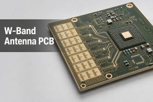
Realistic W-band antenna PCB with integrated array and RF feed structures

What Is a W-Band Antenna PCB?

A W-band antenna PCB is a frequency-sensitive circuit structure in which the board participates directly in radiation, RF feeding, beamforming, packaging or transition to another transmission medium. Small dimensional changes that are harmless at lower frequencies can create measurable phase, loss or impedance differences in W-band channels.

The term does not describe one fixed antenna shape. A PCB can carry a single radiating element, a corporate-feed network, a multi-channel array, SIW cavities, launch structures or the interface between a chipset and a waveguide antenna. A practical “mmwave pcb antenna” design therefore begins by defining which electromagnetic functions belong to the PCB and which belong to the package, connector, waveguide or surrounding enclosure.

W-band projects usually require closer coordination among antenna designers, package engineers, PCB fabricators, assemblers and test engineers. Their models must use compatible material assumptions, reference planes and mechanical dimensions; otherwise a board can meet its drawing yet miss the system target.

Where Are W-Band Antenna PCBs Commonly Used?

W-band antenna PCBs are used where compact antennas, short wavelengths, wide available bandwidth or fine angular resolution justify the added design and validation effort. The exact frequency allocation and product rules depend on the application and region, so the system specification should define the intended operating window.

Common engineering contexts include:

  • short-range and multi-gigabit wireless links;
  • imaging, sensing and research instruments;
  • phased-array and beam-steering platforms;
  • radar development above conventional automotive radar bands;
  • frequency-extender, calibration and laboratory evaluation hardware;
  • compact modules that transition between silicon, PCB and waveguide structures.

Which W-Band Antenna Type Is Best for Your PCB Project?

The best antenna type is the one that meets the radiation, bandwidth, packaging and manufacturing targets with a testable interface. A simple etched structure may reduce part count, while an array, SIW or antenna-in-package approach can better support gain, integration or feed control at the cost of added process sensitivity.

Architecture Typical fit Main manufacturing concern
Etched patch or slot Compact single element or small array Etch geometry, copper profile, dielectric thickness and surrounding metal
Corporate-fed array Higher gain or controlled beam pattern Feed symmetry, cumulative phase error and registration across channels
SIW or PCB waveguide Low-profile guided structures and transitions Via placement, cavity dimensions, plating and launch repeatability
Antenna-in-package Short chip-to-antenna path and dense integration Package-to-board transition, assembly alignment and warpage
Hybrid PCB-to-waveguide System connection to horn or metal waveguide Mechanical datum, aperture alignment, surface contact and fixture repeatability

A “w band patch antenna” can be suitable when its bandwidth, gain and installation environment are compatible with a planar radiator. A “w-band antenna array” is more appropriate when the system needs higher effective aperture or beam steering, but the additional channels make material variation, conductor geometry and assembly alignment harder to control.

What Should Be Confirmed Before W-Band Antenna PCB Design?

Confirm the RF, mechanical, material and validation boundaries before committing the layout. The project should not begin with a generic 50-ohm trace assumption because the usable geometry depends on the transmission structure, laminate construction, copper profile and surrounding reference planes.

The design team should establish:

  • operating frequency range, channel plan and required bandwidth;
  • antenna architecture, polarization, gain and scan requirements;
  • chipset, package, connector, waveguide and enclosure interfaces;
  • material family, target dielectric properties and allowed construction options;
  • stackup, copper profile, conductor definition and registration assumptions;
  • simulation reference planes and de-embedding approach;
  • acceptable amplitude, phase, impedance and radiation-pattern criteria;
  • prototype quantity, assembly state and planned validation stages.

These inputs do not need to become a long document checklist. They need to be consistent. A model based on one dielectric thickness or copper treatment cannot reliably predict a board manufactured with another construction.

How Should a W-Band Antenna Be Placed and Routed on the PCB?

Place the antenna and its feed network as a controlled electromagnetic region, not as ordinary signal routing. Keep the layout consistent with the simulated stackup, reference planes, enclosure and launch geometry, and protect the antenna aperture from copper, components and mechanical features that were absent from the model.

Useful layout controls include:

  • keeping feed paths short, geometrically consistent and free of unplanned neck-downs;
  • preserving the intended ground return and avoiding reference-plane discontinuities;
  • using symmetric routing where array channels require matched phase and amplitude;
  • locating via fences and SIW rows from the electromagnetic design, not from a generic spacing rule;
  • defining copper keepouts around radiating elements and transitions;
  • placing mounting holes, shields, fasteners and enclosure walls in the simulation model;
  • avoiding solder mask or surface treatments over critical RF regions unless the design explicitly includes them.

Via stitching can support ground continuity and field confinement, but more vias are not automatically better. Via diameter, pitch, antipad, plating and distance from the RF structure all affect the local field and manufacturability.

Which Materials and Stackups Affect W-Band Antenna Performance?

Materials and stackups affect W-band performance through dielectric constant, loss, thickness variation, moisture behavior, copper roughness, glass weave and construction repeatability. A material name alone is not enough; the design model should reflect the actual laminate, copper and fabrication construction being purchased.

Cutaway view of multilayer W-band antenna PCB materials, copper layers and via structures

Review these variables together:

  • design Dk and its test method at a relevant frequency;
  • dissipation factor and conductor-loss assumptions;
  • dielectric thickness and its manufacturing tolerance;
  • copper foil type, profile and plated thickness;
  • glass reinforcement or anisotropy when present;
  • bondply, prepreg or adhesive behavior in a hybrid stackup;
  • dimensional stability through lamination and subsequent thermal cycles;
  • surface finish and solder mask interaction with exposed RF conductors.

Low nominal Df does not guarantee low insertion loss if rough copper, long feeds or poor transitions dominate. Likewise, two laminate constructions with similar datasheet Dk values may produce different effective impedance and phase when their reinforcement, resin content or copper profile differs. For a broader material context, see our RF Microwave PCB guide.

How Do Feed Lines, Impedance Matching, Vias and Transitions Affect Performance?

Feed lines and transitions determine how much of the generated W-band energy reaches the antenna with the intended amplitude and phase. The whole path must be modeled across launches, vias, package pads, cavities, connectors and waveguide interfaces; checking only a straight transmission-line coupon leaves the most sensitive discontinuities untested.

At W-band, a transition can add loss or resonance through a small pad, antipad, stub, air gap or registration shift. Channel-to-channel differences can also accumulate through small length and geometry variations. The design should therefore define the reference plane for every reported result and distinguish simulated antenna impedance from the impedance seen through the complete feed and fixture.

Impedance control PCB principles still apply, but a conventional coupon may not represent the antenna feed, via transition or package launch. Use dedicated test structures when the project needs to separate material, line, transition and fixture effects.

What Is the W-Band Antenna PCB Design and Manufacturing Process?

The process should connect electromagnetic design, fabrication engineering and staged verification so that production data preserve the modeled structure. The PCB fabricator should review the stackup and critical geometry before release, while the antenna designer retains responsibility for RF synthesis and system-level performance.

Engineer inspecting a high-frequency antenna PCB under an optical measurement microscope
  1. Define the operating band, antenna architecture, interfaces and validation targets.
  2. Select a manufacturable material system and build the preliminary stackup.
  3. Simulate the antenna, feed network, transitions, package and nearby mechanical features.
  4. Add fabrication tolerances to sensitivity analysis instead of validating only nominal geometry.
  5. Complete PCB DFM review for conductor definition, registration, drilling, plating and lamination.
  6. Fabricate coupons or representative test structures with the prototype panel.
  7. Inspect the bare board before assembly and record actual stackup or dimensional results where required.
  8. Assemble with controlled alignment, reflow profile, flatness and handling conditions.
  9. Measure interconnect behavior and antenna performance using agreed reference planes.
  10. Correlate test results with the model before freezing the production build.

A useful “mmwave pcb design guide” must include this feedback loop. If the prototype fails, the team needs enough coupon, dimensional and fixture data to identify whether the cause is the antenna model, the feed path, fabrication variation, assembly or measurement setup.

Why Does a W-Band Antenna PCB Show High Loss, Weak Gain or Phase Error?

High loss, weak gain and phase error usually come from several interacting sources rather than one obvious defect. Diagnose the signal path in stages and compare nominally identical channels before changing the antenna geometry.

Symptom Likely cause group First check
Higher insertion loss Material loss, copper roughness, long feed or transition loss Compare line and transition test structures before OTA testing
Resonance shifted Dielectric thickness, effective Dk, etch geometry or nearby metal Measure critical dimensions and confirm the built stackup
Weak or distorted pattern Feed imbalance, enclosure interaction, assembly obstruction or fixture scattering Repeat with the agreed mechanical configuration and calibration boundary
Channel phase spread Line-length, weave, copper, registration or package variation Compare matched channels through the same fixture and reference plane
Poor repeatability Connector torque, waveguide alignment, contact, cable movement or calibration drift Re-seat the fixture and run a repeatability study

Do not tune the board from a single unverified measurement. First confirm calibration, fixture repeatability and reference-plane location. Then compare bare-board dimensions, material construction and assembly state against the model.

How Should a W-Band Antenna PCB Be Tested Before Production?

Test a W-band antenna PCB in layers: bare-board quality, RF interconnect behavior and over-the-air antenna performance answer different questions. A PCB supplier can verify fabrication features and agreed electrical structures, but antenna gain and radiation pattern require suitable W-band equipment, fixtures and an OTA method.

W-band antenna PCB mounted in a millimeter-wave laboratory test fixture

A practical validation sequence may include:

  • visual and dimensional inspection of critical conductors, apertures and registration;
  • microsection or construction verification for selected vias and layer relationships;
  • continuity, isolation and agreed impedance or transmission-line coupons;
  • line and transition measurements with defined calibration and de-embedding;
  • channel-to-channel amplitude and phase comparison for arrays;
  • assembled-module checks with the final package, connector or waveguide interface;
  • OTA return loss, gain, pattern, polarization and scan testing when the responsible laboratory capability is confirmed.

W-band characterization commonly uses frequency extenders and waveguide hardware. Fixture design, flange alignment and calibration boundaries must be documented because a fixture error can look like a PCB or antenna defect.

How Do Assembly and Packaging Affect W-Band Antenna Performance?

Assembly and packaging affect W-band performance by changing alignment, standoff, flatness, local dielectric loading and transition geometry. A bare board that matches its drawing can still perform differently after a chipset, shield, radome, heat spreader or waveguide block is installed.

Control the assembly variables that are included in the RF model:

  • package placement and rotation relative to feed structures;
  • solder volume, collapse and standoff for flip-chip or fine-pitch interfaces;
  • board and package warpage through reflow;
  • underfill, adhesive or coating near active RF regions;
  • connector or waveguide flange alignment and fastener sequence;
  • shield, enclosure and absorber position;
  • cleanliness and surface contamination around exposed conductors.

If assembly is outsourced separately from PCB fabrication, provide the assembler with the RF-sensitive keepouts and mechanical datums. Standard placement tolerances may not describe the relative alignment that the antenna transition actually needs.

What Factors Affect W-Band Antenna PCB Cost?

W-band antenna PCB cost is driven by material choice, stackup complexity, tolerance control, prototype learning and validation—not by board area alone. Early agreement on which characteristics are truly critical can prevent unnecessary controls while protecting RF performance.

The main cost drivers are:

  • specialty laminate availability and minimum purchase quantities;
  • hybrid or sequential lamination construction;
  • thin dielectric layers and tight thickness control;
  • fine conductor geometry, copper-profile requirements and etch compensation;
  • registration demands across antenna, feed and via structures;
  • small or dense plated holes, SIW rows and backdrilling when applicable;
  • dedicated coupons, dimensional reports, microsections or RF test structures;
  • assembly alignment, package complexity and special fixtures;
  • prototype iterations needed to correlate simulation and measured results;
  • production quantity, panel utilization and accepted yield window.

Cost should be reviewed against the validation plan. Removing a useful test structure may reduce initial panel cost but make a failed prototype harder to diagnose. Conversely, specifying a universal tight tolerance without sensitivity evidence can add cost without improving the antenna.

FAQ About W-Band Antenna PCB Projects

Is W-band always defined as 75-110 GHz?

75-110 GHz is a common engineering definition for the W-band, but applications, instruments and regulations may use narrower windows. State the exact operating range and channel plan in the project specification rather than relying only on the band name.

Can a w band patch antenna be fabricated as a conventional multilayer PCB?

It can use familiar PCB processes, but the construction may need tighter control of dielectric thickness, copper geometry, surface condition and registration than a conventional digital board. The antenna model must use the proposed stackup and manufacturing tolerances.

Which laminate properties matter most for a mmwave pcb antenna?

Design Dk, dissipation factor, thickness tolerance, copper roughness, reinforcement structure, moisture behavior and dimensional stability can all matter. Their relative importance depends on whether loss, phase consistency, resonance or mechanical stability dominates the design.

Does a PCB supplier validate antenna gain and radiation pattern?

Not automatically. A PCB supplier may inspect construction, dimensions and agreed RF coupons. Gain, radiation pattern, polarization and scan performance require suitable W-band fixtures and OTA equipment, so the responsible test party and acceptance method must be confirmed for each project.

What project information should be confirmed before production?

Confirm the operating range, antenna type, final stackup, named laminate, copper construction, critical geometry, mechanical interfaces, assembly state, quantity and acceptance method. Provide Gerber or ODB++ data plus relevant package or waveguide drawings when they are part of the manufactured interface.

Why can nominally identical antenna channels show different phase or gain?

Small differences in feed length, dielectric construction, glass weave, copper profile, registration, package alignment or fixture contact can accumulate across channels. Compare the channels through the same calibrated setup and inspect actual geometry before changing the design.

How Can EBest Circuit Support Your W-Band Antenna PCB Project?

EBest Circuit supports RF and high-frequency PCB manufacturing, impedance-controlled PCB work, impedance testing and engineering review for available high-frequency material systems. Because W-band performance depends on the exact stackup, copper construction, antenna topology, transitions and validation method, we review each design for manufacturability and sourcing feasibility rather than promise one universal process window.

Send the target frequency range, antenna architecture, Gerber or ODB++ data, stackup, material and copper requirements, critical tolerances, package or waveguide interface drawings, assembly information, quantity and RF acceptance plan to our engineering team at sales@bestpcbs.com. We can review the PCB manufacturing and assembly scope with your team. Antenna synthesis, W-band VNA measurement and OTA gain or pattern validation are included only when the responsible capability is confirmed for the specific project.

You may also like

Pull Up vs Pull Down Resistor: How to Choose the Right One

August 19th, 2026

A pull up vs pull down resistor comparison comes down to one basic decision: what logic state should a signal have when no device is actively driving it? A pull-up resistor keeps the signal HIGH by connecting it to the positive supply through resistance, while a pull-down resistor keeps it LOW by connecting it to ground. Both prevent a high-impedance digital input from sitting at an undefined voltage.

The difference is simple, but choosing the right arrangement becomes more important in real circuits involving MCU GPIO, reset and enable pins, sensors, open-drain outputs, IÂČC buses, and power-up sequencing. This guide explains how pull-up and pull-down resistors work, when to use each type, how to select a suitable resistor value, and what engineers should check before a design moves from schematic to PCB production.

pull up vs pull down resistor

Pull Up vs Pull Down Resistor: What Is the Difference?

The main difference between pull-up and pull-down resistors is the default logic state they establish.

A pull-up resistor connects the signal to VCC, so an undriven input normally reads HIGH. A pull-down resistor connects the signal to ground, so the same type of input normally reads LOW.

Design PointPull-Up ResistorPull-Down Resistor
Resistor connectionSignal to VCCSignal to GND
Default logic stateHIGHLOW
Typical active stateLOWHIGH
Common switch connectionSignal to GNDSignal to VCC
Common usesOpen-drain signals, reset lines, interrupts, MCU inputsEnable pins, gate control, default-low inputs
Logic behaviorOften active-lowOften active-high

Neither method is inherently better. The correct choice depends on what the circuit should do when the switch, controller, or external signal is inactive.

A useful first rule is:

Default HIGH → use a pull-up.
Default LOW → use a pull-down.

For open-drain or open-collector signals, a pull-up is normally required because the output can actively pull the line LOW but cannot actively drive it HIGH.

pull up vs pull down resistor

How Do Pull-Up and Pull-Down Resistors Work?

Pull-up and pull-down resistors provide a weak connection to one power rail while allowing another device to override that state.

Pull-up resistor circuit

A pull up resistor circuit typically connects:

VCC → resistor → signal node

A switch, transistor, or open-drain output can then connect the signal node to ground.

When nothing drives the line, the resistor brings the node toward VCC. When the signal is pulled to ground, the resistor limits the current between VCC and GND.

For example, with a 3.3 V supply and a 10 kΩ resistor:

I = V / R = 3.3 / 10,000 ≈ 0.33 mA

Pull-down circuit

A pull down circuit reverses the arrangement:

Signal node → resistor → GND

An external source can then drive the node toward VCC. When that source is removed, the resistor brings the signal back toward ground.

The resistor therefore does two jobs: it establishes a known idle voltage and limits current when another device drives the line in the opposite direction.

This is why simply connecting a signal directly to VCC or GND is not equivalent to using a pull resistor. A direct connection could create excessive current when another device attempts to drive the opposite state.

pull up vs pull down resistor

Why Are Pull-Up and Pull-Down Resistors Needed?

Digital inputs often have very high input impedance. If an input is disconnected and has no pull-up or pull-down path, it can become a floating input.

A floating node may respond to leakage current, residual charge, nearby switching signals, EMI, or capacitive coupling. The voltage can move between valid HIGH and LOW thresholds instead of remaining at a predictable level.

That can create behavior such as:

  • an MCU input changing state without a valid command;
  • a reset or enable pin activating unexpectedly;
  • a MOSFET control node entering an unintended state;
  • intermittent sensor or digital-interface behavior;
  • unstable operation during startup or controller reset.

The startup condition deserves particular attention in production electronics. Firmware does not configure every GPIO immediately when power is applied. An external pull resistor can establish the required state before firmware runs.

For example, an enable pin that must remain inactive during power-up may use a pull-down resistor even if the microcontroller later controls that signal directly.

Pull resistors are therefore not merely “logic accessories.” They help define circuit behavior during the moments when no active driver is in control.

When Should You Use a Pull-Up or Pull-Down Resistor?

The easiest way to choose between them is to start with the required idle state and then check how the active device drives the signal.

Use a pull-up resistor when:

  • the signal should default HIGH;
  • a switch or transistor pulls the line toward ground;
  • the signal is active-low;
  • an open-drain or open-collector output is used;
  • reset, interrupt, or chip-select lines should remain HIGH when inactive;
  • a communication interface requires a passive HIGH state.

Use a pull-down resistor when:

  • the signal should default LOW;
  • an external device drives the node toward VCC;
  • an enable pin must remain disabled during startup;
  • a transistor or MOSFET control input should stay off until commanded;
  • a disconnected external input should be interpreted as logic 0.

Open-drain buses are a particularly important case. IÂČC SDA and SCL lines, for example, are normally pulled HIGH through resistors while connected devices pull them LOW when transmitting.

The decision should also consider power-up behavior. If the correct logic state must exist before the MCU initializes, relying only on firmware configuration may not be sufficient.

In other words, choose the resistor according to what the hardware must do when software is not yet in control.

pull up vs pull down resistor

How Do You Choose a Pull Up Resistor Value?

There is no universal pull up resistor value. 10 kΩ is common in slow digital-input circuits, but it should be treated as a starting point rather than a default engineering rule.

The value should be selected by checking four main factors:

  • Logic thresholds: the resulting voltage must remain inside the valid HIGH or LOW region specified by the IC.
  • Leakage current: a very high resistance can allow device leakage to shift the signal away from the intended level.
  • Current consumption: a lower resistance creates a stronger pull but increases current when another device drives the opposite state.
  • Capacitance and switching speed: resistance combines with line and input capacitance to form an RC network. Higher resistance generally produces slower passive transitions.

Typical values illustrate the tradeoff:

Resistor ValueGeneral BehaviorTypical Consideration
1 kΩStrong pull, faster edgeHigher active-state current
4.7 kΩModerate pullCommon compromise in many digital circuits
10 kΩLower currentOften suitable for low-speed GPIO
47 kΩ or higherVery low currentMore sensitive to leakage, noise, and capacitance

These are examples, not universal design values.

For IÂČC and other open-drain interfaces, resistor selection requires particular care because bus capacitance and rise-time limits directly affect the acceptable resistance range.

For a production PCB, the better approach is to check the IC datasheet and interface specification rather than copying a resistor value from another schematic.

pull up vs pull down resistor

Internal vs External Pull-Up and Pull-Down Resistors

Many microcontrollers provide configurable internal pull-up and sometimes pull-down resistors. These are convenient because they reduce component count and can be enabled through the GPIO configuration.

Internal resistors are often sufficient for:

  • simple buttons and switches;
  • configuration straps;
  • low-speed GPIO inputs;
  • non-critical digital signals where the exact resistance is not important.

External resistors provide more design control.

Internal Pull ResistorExternal Pull Resistor
No additional componentRequires PCB and BOM space
Convenient for GPIOResistance can be selected precisely
Enabled by firmware/configurationCan define state immediately at power-up
Resistance may vary more widelyBetter control of current and RC timing
Good for many low-speed inputsBetter for interfaces with defined electrical requirements

The most important difference in a real product is often when the pull becomes active.

An external resistor works as soon as the relevant power rail is present. An internal resistor may not become active until the MCU reaches a particular startup state or firmware configures the GPIO.

That distinction matters for reset pins, power enables, safety-related control signals, and circuits where another IC becomes active before the main controller.

External components are also usually preferable when rise time, leakage margin, interface compliance, or resistance tolerance must be engineered rather than simply accepted.

pull up vs pull down resistor

How Are Pull-Up and Pull-Down Resistors Used in Microcontroller Circuits?

A pull up resistor in microcontroller designs can appear in many places beyond a simple pushbutton.

Common MCU applications include:

GPIO inputs.

  • A pull resistor keeps an unused or externally controlled input at a defined level until another circuit changes it.

Reset and enable pins.

  • Pull resistors establish a safe startup condition before firmware begins controlling the board.

Interrupt signals.

  • Many sensors and peripheral ICs use open-drain interrupt outputs, making a pull-up necessary to create the HIGH state.

IÂČC communication.

  • SDA and SCL use open-drain signaling and require pull-ups whose values suit the operating voltage, bus capacitance, and required rise time.

Configuration pins.

  • Pull-up or pull-down resistors can define boot modes, addresses, or operating states when the system powers on.

Arduino provides a familiar example. INPUT_PULLUP allows supported microcontrollers to enable an internal pull-up for a GPIO input, so a pushbutton can connect between the pin and ground. In that arrangement, the unpressed state reads HIGH and the pressed state reads LOW.

For production MCU boards, however, engineers usually need to look beyond the basic pull up resistor Arduino example. Startup timing, external peripherals, power domains, leakage, signal speed, and what happens before firmware executes can all determine whether an internal resistor is sufficient or an external component is the safer choice.

Common Pull-Up and Pull-Down Resistor Mistakes

Pull resistors are simple components, which makes them easy to overlook during schematic and PCB review. Many problems come from treating a familiar value or reference design as universally applicable.

Common mistakes include:

  • Leaving high-impedance inputs floating. An unused or externally disconnected input may need a defined bias rather than being left open.
  • Using 10 kΩ automatically. A familiar value can still be too weak, too slow, or unnecessarily strong for a particular circuit.
  • Ignoring startup behavior. An internal MCU pull may not control the signal during the earliest stage of power-up.
  • Forgetting active-low logic. With a pull-up switch input, the active condition may read LOW rather than HIGH.
  • Ignoring bus capacitance. On open-drain interfaces such as IÂČC, excessive resistance can produce slow rising edges.
  • Using the wrong BOM or population option. A schematic may show optional pull resistors while the production BOM or assembly drawing specifies a different DNP/populated condition.

The final check should therefore extend beyond the schematic symbol. Confirm the resistor value, voltage rail, logic polarity, startup condition, populated/DNP status, and interface requirements.

For MCU, sensor, control, and embedded PCBs, these checks are especially useful before fabrication because a small biasing error can otherwise appear later as an intermittent communication, startup, or functional-test problem.

FAQs About Pull Up vs Pull Down Resistor

Can a signal have both a pull-up and a pull-down resistor?

Yes, but the two resistors then form a voltage divider. The resulting voltage depends on their resistance ratio, so this arrangement should only be used when that intermediate bias level is intentional.

Do output pins need pull-up or pull-down resistors?

A normal push-pull output usually drives both HIGH and LOW actively, so it does not need a pull resistor for basic operation. Open-drain or open-collector outputs are different because they typically require a pull-up to create the HIGH state.

Is a 10 kΩ pull-up resistor suitable for every digital input?

No. 10 kΩ is useful in many low-speed circuits, but leakage current, logic thresholds, capacitance, switching speed, and power requirements can make another value more appropriate.

Can pull-up resistors be used with both 3.3 V and 5 V circuits?

Yes, provided the resistor connects to a voltage that is valid for every device on that signal. The pull-up voltage must not exceed the input-voltage limit of any connected IC.

Should an external pull resistor be added if the MCU already has an internal one?

Not necessarily. Internal pulls are convenient for many GPIO inputs, but an external resistor is preferable when the signal needs a defined state before firmware initialization, a specific resistance, stronger biasing, or controlled rise time.

If your MCU, sensor, industrial control, or embedded design is moving from schematic to production, you can send the Gerber/PCB files, BOM, and project requirements to sales@bestpcbs.com. EBest Circuit can support engineering review, PCB fabrication, component sourcing, PCBA assembly, testing, and quotation for the next production stage.

You may also like

COB LED Aluminum PCB Manufacturing for High-Power LED Modules

August 19th, 2026

A COB LED aluminum PCB combines electrical routing with an efficient thermal path for high-power LED modules. Its performance depends on the dielectric layer, copper layout, LED interface and metal base working together. EBest Circuit supports metal core PCB projects from PCB design and prototyping to component sourcing, PCB assembly and mass production.

Are you worried about these COB LED aluminum PCB problems?

  • The COB LED still runs too hot after changing from FR4 to an aluminum PCB.
  • You are unsure which thermal conductivity, dielectric thickness or copper weight is actually needed.
  • The prototype works, but material or assembly consistency becomes difficult in production.

As a professional metal core PCB manufacturer, EBest Circuit can solve these issues by matching the PCB construction to the LED package, electrical load and thermal requirements. Below are our solutions:

  • Improve the Thermal Path
    Review the dielectric, copper spreading area and metal-base construction to reduce unnecessary thermal resistance.
  • Select the Right PCB Specifications
    Define thermal conductivity, dielectric thickness, copper weight and aluminum thickness from the actual LED power and current.
  • Keep Production Consistent
    Confirm the construction during prototyping and maintain the approved materials and assembly requirements in volume production.

Developing a high-power COB LED aluminum PCB? Send your PCB files, LED datasheet and project requirements to sales@bestpcbs.com for a quotation.

COB LED Aluminum PCB

What Is a COB LED Aluminum PCB and Why Is It Used for High-Power LEDs?

A COB LED aluminum PCB is a metal-based PCB designed to carry current and move heat away from a COB LED module. It is widely used in high-power lighting because the aluminum base can spread concentrated heat more effectively than a conventional FR4 structure.

A common single-layer construction is:

Copper circuit → thermal dielectric → aluminum base

In the finished LED module, heat typically travels through:

LED junction → LED package → solder or thermal interface → copper → dielectric → aluminum base → heat sink

The copper carries current and spreads heat around the LED area. The dielectric provides electrical isolation while transferring heat into the aluminum base, which distributes it across a larger surface.

The PCB should be designed around the actual COB LED package. Confirm the pad layout, thermal-contact area, optical center, package dimensions and mounting method from the LED datasheet before finalizing the footprint.

How Does a COB LED Aluminum PCB Improve Heat Dissipation?

A COB LED aluminum PCB spreads heat from the small COB LED area into a much larger metal surface. Heat moves through the copper and dielectric before reaching the aluminum base, so these intermediate layers directly affect thermal performance.

Three parameters matter most:

  • Dielectric Thermal Conductivity
    Higher conductivity improves heat transfer through the insulating layer. It should be evaluated together with dielectric thickness rather than used as a stand-alone specification.
  • Dielectric Thickness
    A thinner dielectric generally lowers thermal resistance, but it still needs enough dielectric strength and electrical isolation for the application.
  • Effective Heat-Transfer Area
    Adequate copper and thermal-contact area helps spread heat before it crosses the dielectric. This is especially important when a high-power COB concentrates heat into a small footprint.

Which Applications Use COB LED Aluminum PCBs and COB Light Engines?

COB LED aluminum boards are mainly used where high light output and concentrated heat occur in the same compact assembly.

Typical applications include:

  • Spotlights and Downlights: Compact products with limited space for the PCB and cooling structure.
  • Track and Architectural Lighting: Modules requiring stable output and accurate LED positioning.
  • High-Bay and Industrial Lighting: Higher-power products designed for long operating periods.
  • Streetlights and Floodlights: Outdoor lighting exposed to high power and elevated enclosure temperatures.
  • Stage Lighting: High-output sources operating at relatively high current.
  • Machine-Vision Lighting: Applications where stable illumination affects imaging and inspection quality.
  • Optical Inspection Equipment: Systems requiring precise LED positioning relative to optics.
  • Medical Illumination: Compact lighting modules requiring stable operation and repeatable assembly.
  • Projector and Imaging Light Sources: High-brightness systems with concentrated thermal loads.
  • COB Light Engines: Integrated modules combining the LED, PCB, optics and cooling structure.

For a COB LED module aluminum PCB, total LED power, operating time, ambient temperature and available cooling area matter more than the number of LEDs alone.

COB LED Aluminum PCB Application

How Should Thermal Conductivity, Dielectric Thickness and Copper Weight Be Selected?

For a COB LED aluminum PCB, these values should follow the LED power, operating current, thermal target and electrical-isolation requirement.

  • Select Thermal Conductivity From Heat Density
    Higher thermal conductivity is useful when the COB LED produces concentrated heat or when PCB area is limited. Moderate-power designs may not require the highest thermal class.
  • Keep the Dielectric Thin Without Sacrificing Isolation
    A thinner dielectric lowers thermal resistance, but it still needs to meet operating-voltage, dielectric-strength and manufacturing requirements.
  • Match Copper Weight to Current and Geometry
    Higher current may require heavier copper, but trace width and available copper area are equally important. Heavy copper does not correct an undersized current path.
  • Provide Enough Copper Around the Heat Source
    Larger copper areas around the COB LED improve lateral heat spreading before heat passes through the dielectric.
  • Avoid Increasing Specifications Without Finding the Limitation
    A higher W/m·K material or heavier copper provides little benefit if another part of the PCB construction limits thermal performance.
  • Validate the Construction During Prototyping
    Test the selected copper and dielectric construction at the intended LED power before freezing the design for production.

How Should the COB LED Footprint and Thermal Pad Match the Aluminum PCB?

Use the actual COB LED package drawing rather than a generic footprint. Similar-sized COB LEDs can have different electrical pads, thermal regions and mounting structures.

Check the following before release:

  • Electrical Pads: Match pad dimensions, spacing and polarity to the datasheet.
  • Thermal-Contact Area: Align the PCB thermal region with the package structure.
  • Optical Center: Position the emitting area correctly relative to the lens or reflector.
  • Solder Mask Clearance: Keep solderable areas fully exposed.
  • Package Outline: Leave enough clearance around the LED body.
  • Mounting Holes: Align the PCB with the LED module and heat sink.
  • Keep-Out Areas: Keep components and hardware away from optical or mounting areas.
  • Heat-Sink Interface: Maintain a flat and consistent backside contact area where required.

For soldered packages, solder volume also matters. Too much solder can increase stand-off or tilt the LED, while large voids under the thermal region reduce effective heat transfer.

Stencil openings, paste volume and reflow conditions should therefore be matched to the thermal-pad geometry.

When Should You Choose an Aluminum-Core PCB Instead of a Copper-Core PCB for COB LEDs?

Use an aluminum-core PCB when the required LED temperature can be achieved with the correct dielectric and cooling structure. Move to copper only when the thermal demand exceeds what an optimized aluminum MCPCB can support.

Choose an aluminum-core PCB when:

  • The Heat Density Is Within the Range of a Conventional MCPCB
    Aluminum works well for many spotlights, downlights, industrial lights, streetlights and other high-power LED modules.
  • The Dielectric Can Meet the Thermal Target
    If the correct dielectric conductivity and thickness provide enough thermal performance, a copper base adds limited value.
  • PCB Weight Matters
    Aluminum is lighter than copper and is suitable for larger lighting assemblies.
  • A Standard MCPCB Structure Is Preferred
    Aluminum-core PCB is widely used for both prototypes and volume LED production.
  • The External Cooling System Is Adequate
    If heat can move effectively from the PCB into the final cooling structure, aluminum is usually sufficient.

Consider a copper-core PCB when:

  • The COB LED Produces Very High Local Heat Flux
    A highly concentrated thermal load may benefit from stronger lateral heat spreading.
  • An Optimized Aluminum PCB Still Runs Too Hot
    Copper becomes more relevant after the dielectric and other major thermal limitations have already been addressed.
  • The Design Requires a Very Low-Resistance or Direct Thermal Path
    Some specialized LED constructions use copper-based structures to shorten the path between the heat source and metal substrate.
  • Thermal Performance Matters More Than Weight
    Copper provides higher bulk thermal conductivity but also increases PCB weight.

Use aluminum when it meets the thermal target. Move to copper only when the optimized aluminum structure is no longer sufficient.

What Steps Are Used to Manufacture and Assemble a High-Power COB LED Aluminum PCB?

A high-power COB LED aluminum PCB needs a controlled manufacturing process so the approved material, circuit and mechanical structure remain consistent through assembly.

Step 1: Review the Design and Material Requirements

Confirm the COB LED footprint, copper weight, dielectric, aluminum thickness, board dimensions, mounting holes, surface finish and required thermal interface.

Step 2: Prepare the Aluminum-Based Laminate

Use the approved copper, dielectric and aluminum construction. Material substitutions should be reviewed before production because they can change thermal and mechanical performance.

Step 3: Form and Etch the Copper Circuit

Image and etch the LED pads, power paths and supporting circuitry. Trace width and spacing must be compatible with the selected copper thickness.

Step 4: Drill and Profile the PCB

Produce mounting holes, slots and the finished outline according to the mechanical drawing. These features may align directly with the heat sink, lens holder or enclosure.

Step 5: Apply Solder Mask and Surface Finish

Keep COB LED pads and other solderable areas correctly exposed. The surface finish should match the intended assembly process.

Step 6: Print Solder Paste and Place Components

Control paste volume around the LED pads and place the COB LED accurately. Positioning may affect both electrical connection and optical alignment.

Step 7: Complete Reflow and Assembly Inspection

Use an appropriate reflow profile and check solder wetting, component orientation, stand-off and visible defects after soldering.

Step 8: Mount the PCB to the Cooling Structure

Install the assembled PCB using the specified TIM, screws or clamping arrangement. Avoid uneven contact or mechanical stress on the LED package.

Step 9: Verify Electrical and Thermal Performance

Operate the assembled module at the specified load and confirm current, LED function and operating temperature before volume production.

COB LED Aluminum PCB Manufacturing

What Steps Are Used to Inspect and Test a COB LED Aluminum PCB Before Shipment?

Inspection should cover the characteristics that can affect electrical operation, assembly fit and heat transfer.

Step 1: Verify Material and PCB Construction

Check the aluminum base, dielectric, copper thickness and finished PCB thickness against the approved specification.

Step 2: Check Dimensions and Mounting Features

Inspect the PCB outline, slots, mounting holes and critical dimensions to confirm fit with the mechanical assembly.

Step 3: Inspect Circuit and Surface Quality

Use visual inspection and AOI where applicable to identify opens, shorts, damaged pads, contamination, scratches or solder-mask registration defects.

Step 4: Perform Electrical and Insulation Testing

Verify circuit continuity and electrical isolation between the copper circuit and aluminum base.

Step 5: Check PCB Flatness

Inspect flatness when the PCB backside forms part of the thermal interface. Excessive warpage can reduce contact with the cooling surface.

Step 6: Inspect COB LED Placement and Soldering

Verify polarity, orientation, LED position, solder wetting and the condition of the main thermal-contact area.

Step 7: Perform Functional Testing

Operate the assembled module under the specified electrical conditions. Check for abnormal brightness, flicker, current behavior or other functional problems.

Step 8: Complete Thermal Validation

Test the module with the intended or representative cooling structure until temperature approaches a stable condition. Use thermocouples, thermal imaging or the LED manufacturer’s recommended method where appropriate.

Step 9: Confirm Production Consistency

Check that production boards use the approved materials, PCB construction and assembly requirements established during prototype validation.

COB LED Aluminum PCB Testing

What COB LED Aluminum PCB Manufacturing Capabilities Can We Provide?

Manufacturing capability determines whether the required COB LED aluminum PCB construction can be produced consistently from prototype to volume production. The table below summarizes our main MCPCB process capabilities for design and manufacturing reference.

ItemCapabilities
Maximum Layer CountUp to 10 layers
PCB Thickness0.3–4.0 mm
Maximum Board SizeUp to 610 × 1220 mm (24 × 48 in.)
Copper Weight0.5–10 oz
Minimum Trace / Space0.15 / 0.15 mm (6 / 6 mil)
Minimum Hole Diameter0.30 mm (12 mil)
Minimum Punch Hole Diameter3.0 mm (0.12 in.)
Minimum Hole Spacing0.40 mm (16 mil)
Maximum Aspect Ratio12:1
Minimum Solder Pad Diameter0.40 mm (16 mil)
Thermal Conductivity0.8–1.5 W/m·K standard; 2.0–6.0 W/m·K high thermal conductivity
Warp and Twist< 0.75%
FlammabilityUL 94V-0
Thermal Stress6 × 10 sec at 288°C
Surface FinishENIG, Flash Gold, Hard Gold, Selective Gold Plating, HASL, Lead-Free HASL, OSP, Immersion Silver, Immersion Tin

Case Study: High-Power COB LED Aluminum PCB From Prototype to Production

Project Background

A high-power COB LED module required an aluminum PCB connected to an external heat sink. The board had to provide a reliable thermal path while maintaining the correct LED position, mounting-hole alignment and mechanical fit.

Project Requirements

The PCB needed to:

  • Carry the required COB LED current
  • Transfer heat effectively to the cooling structure
  • Use an appropriate dielectric, copper weight and aluminum base
  • Match the LED footprint and thermal-contact area
  • Maintain PCB flatness and mounting accuracy
  • Support prototype assembly and later production

Our Solution

EBest Circuit reviewed the COB LED datasheet, PCB layout and mechanical drawing before prototype fabrication.

The main actions included:

  • Matching the COB LED footprint and thermal area to the package
  • Reviewing dielectric thickness, copper weight and aluminum construction
  • Providing sufficient copper around the main heat source
  • Controlling PCB flatness and mounting-hole alignment
  • Checking soldering, TIM contact and mechanical fit during prototype assembly
  • Maintaining the approved construction for production

Results

Prototype validation confirmed:

  • Stable COB LED mounting and alignment
  • Consistent PCB-to-heat-sink contact
  • A controlled thermal path
  • Reliable electrical and assembly performance
  • A repeatable construction for volume production

The approved PCB construction and assembly requirements were then carried forward into production.

What Specifications and Files Are Required for a COB LED Aluminum PCB Quote?

For a COB LED aluminum PCB quote, provide:

Bare PCB:

  • Gerber files
  • NC drill files
  • Board dimensions
  • Mechanical drawing
  • Finished PCB thickness
  • Copper weight
  • Aluminum thickness
  • Thermal conductivity requirement
  • Dielectric thickness or material requirement
  • Surface finish
  • Solder mask requirement
  • Quantity
  • Special tolerance or testing requirements

PCB Assembly:

  • BOM
  • Pick-and-place file
  • Assembly drawing
  • COB LED part number and datasheet
  • Polarity information
  • Functional-test requirements

For Thermal Review:

  • LED operating power and current
  • Heat-sink drawing
  • TIM specification
  • Mounting method
  • Expected ambient temperature
  • Maximum allowable operating temperature

If some specifications are still open, send the available project files first for review.

Why Choose EBest Circuit for COB LED Aluminum PCB Manufacturing?

With more than 20 years of PCB manufacturing experience, EBest Circuit supports COB LED aluminum PCB projects from prototypes through mass production.

  • One Supplier From Prototype to Production
    PCB prototyping, Metal Core PCB manufacturing, component sourcing and PCB assembly can be coordinated through EBest Circuit, reducing supplier handoffs.
  • Metal Core PCB Manufacturing
    Our PCB range includes Metal Core PCB / MCPCB, supporting COB LED modules and other thermal-management applications.
  • Capacity for Volume Production
    EBest Circuit has approximately 260,000 sq. ft. (28,900 mÂČ) of monthly PCB manufacturing capability.
  • Support for Urgent Projects
    Expedited service is available for eligible projects, with qualifying urgent boards capable of shipment within 24 hours after requirements are confirmed.
  • Quality and Compliance
    EBest Circuit holds ISO 9001:2015, IATF 16949, ISO 13485:2016, AS9100D, UL, RoHS and REACH credentials.

Welcome to contact us if you have any request for COB LED aluminum PCB.

FAQs About COB LED Aluminum PCBs

Q1: Does a COB LED need a constant-current driver?
A1: Usually yes. A high-power COB LED is normally driven by a constant-current driver so current remains controlled as forward voltage changes. If the module already includes current regulation, follow its datasheet.

Q2: Should multiple COB LEDs be connected in series or parallel?
A2: Series connection is generally easier to control because each COB receives the same current. Parallel branches need current balancing because forward-voltage differences can produce unequal current sharing.

Q3: How should the LED driver voltage range match a COB LED?
A3: The driver’s output-voltage range must cover the forward voltage of the COB LED or complete LED string. Add the forward voltages of series-connected COB LEDs before selecting the driver.

Q4: Can a high-power COB LED be dimmed with PWM?
A4: Yes, when the driver supports it. Use the dimming method specified by the driver manufacturer rather than switching LED power directly.

Q5: Is it better to run a COB LED below its maximum rated current?
A5: Often yes. Lower current reduces thermal load and provides more operating margin. Select the working current from the LED manufacturer’s current, temperature and light-output data.

Q6: Can a COB LED be connected or disconnected while the driver is powered?
A6: It is better to avoid it. Hot-plugging can expose the COB LED to electrical transients. Turn the driver off unless the system is specifically designed for hot swapping.

Q7: Can a reflector or lens touch the COB LED?
A7: Optical parts should not press directly against the emitting surface or electrical contacts. Use a suitable holder to maintain alignment and prevent damage.

Q8: Can a failed COB LED be replaced on the MCPCB?
A8: In many designs, yes. Replaceability depends on the attachment method and thermal mass of the MCPCB. Rework temperature and heating time need careful control.

Q9: Should a high-power COB LED system include overtemperature protection?
A9: It is useful when cooling conditions can vary. Temperature sensing can reduce LED current or shut the system down if temperature exceeds the defined limit.

Q10: What happens if one parallel COB LED branch fails open?
A10: The remaining branches may carry more current when they share one constant-current source. Parallel designs should consider current balancing or independent current regulation.

Conclusion

A reliable COB LED aluminum PCB depends on the dielectric, copper layout, LED interface and metal substrate being matched to the actual electrical and thermal load.

EBest Circuit supports metal core PCB manufacturing, prototyping, component sourcing, PCB assembly and mass production. For a high-power COB LED aluminum PCB, COB LED module or light engine project, send your files and requirements to sales@bestpcbs.com for a quotation.

You may also like

Power Resistor: How It Works and How to Choose One

August 19th, 2026

A power resistor is used when a circuit needs to dissipate more electrical energy than a standard signal-level resistor can comfortably handle. These components are common in power supplies, motor drives, battery systems, inverters, charging equipment, and industrial controls, where current, voltage, or transient energy can generate substantial heat.

Choosing the right power resistor involves more than matching the resistance value. Power rating, working voltage, pulse capability, operating temperature, construction, and mounting conditions all affect performance. This guide explains how power resistors work and what to consider when selecting one for a real circuit.

power resistor

What Is a Power Resistor?

A power resistor is a resistor designed to dissipate relatively large amounts of electrical power as heat while maintaining its specified resistance.

Like other resistors, it limits current or creates a controlled voltage drop. The main difference is its ability to manage a higher thermal load.

The basic power relationships are:

  • P = V × I
  • P = IÂČ Ă— R
  • P = VÂČ Ă· R

Where P is power, V is voltage, I is current, and R is resistance.

For example, if 2 A flows through a 10 Ω resistor:

P = 2ÂČ Ă— 10 = 40 W

The resistor must therefore manage about 40 W of heat under that operating condition.

This does not mean a 40 W resistor should automatically be selected. Continuous operation near the maximum rating may leave little thermal margin, especially inside a warm enclosure or without sufficient airflow.

Power resistors use different constructions to move heat away from the resistive element. Depending on the component, heat may be released into the surrounding air, transferred through the PCB, or conducted into a chassis or heatsink.

power resistor

When to Use a High Power Resistor?

A high power resistor is appropriate when continuous power, pulse energy, or operating temperature exceeds what a conventional resistor can safely handle.

There is no universal wattage at which a resistor becomes “high power.” The required rating depends on the application.

Typical situations include:

  • capacitor discharge;
  • inrush current limiting;
  • motor braking;
  • load testing;
  • current limiting;
  • repeated pulse absorption;
  • high-temperature operation.

A higher wattage rating does not cause a resistor to consume more power. Circuit conditions determine the actual dissipation.

For example, a 100 Ω resistor with 10 V across it dissipates:

P = 10ÂČ Ă· 100 = 1 W

A 2 W, 5 W, or 20 W version would still dissipate approximately 1 W in the same circuit. The higher-rated resistor simply provides more thermal capacity.

When choosing a high wattage resistor, however, wattage should not be the only consideration. Maximum working voltage, pulse rating, inductance, physical size, and mounting method can be equally important.

For switching circuits or repetitive pulses, check the manufacturer’s overload or pulse-energy data rather than relying only on the continuous power rating.

Which Type of Resistor Is Used for High Power Applications?

The best resistor for a high-power application depends on continuous wattage, pulse energy, available space, required precision, and thermal conditions.

Wirewound resistors

  • Wirewound resistors offer good power handling and overload capability. They are widely used in motor drives, power supplies, braking systems, and load banks. Their wound construction can introduce inductance, so low-inductance designs may be preferred in fast-switching circuits.

Ceramic or cement resistors

  • A ceramic resistor or cement resistor provides a robust and economical option for current limiting, discharge circuits, snubbers, and general power electronics.

Aluminum-housed resistors

  • These resistors transfer heat efficiently into a chassis or heatsink. They are useful when relatively high continuous power must be handled in a compact space.

Thick-film power resistors

  • Thick-film designs can combine compact size, relatively high resistance values, and low inductance, making them useful in modern power electronics.

Foil resistors

  • A foil resistor is more suitable when power handling must be combined with tight tolerance or low temperature coefficient.

There is therefore no single answer to which type of resistor is used for high power applications. The correct choice depends on whether the main design constraint is heat, pulse energy, precision, size, or high-frequency behavior.

power resistor

What Is a Resistor Power Rating?

A resistor power rating indicates how much electrical power a resistor can dissipate under specified conditions without exceeding its allowable temperature.

Power ratings are normally expressed in watts. Common values range from fractions of a watt to tens, hundreds, or even thousands of watts for industrial resistor assemblies.

A 50 W resistor rated power, however, does not necessarily mean the component can continuously dissipate 50 W under every condition.

The published rating may assume:

  • a defined ambient or case temperature;
  • sufficient airflow;
  • a particular PCB layout;
  • mounting on a metal chassis;
  • installation on a specified heatsink.

As temperature increases, allowable power usually decreases. This relationship is shown in the manufacturer’s derating curve.

A practical selection should therefore satisfy:

Actual power dissipation < Allowable power under real operating conditions

The nominal wattage is only the starting point.

Continuous-load designs should also leave suitable thermal margin, while pulse applications require separate verification of pulse duration, repetition rate, and overload capability. A resistor that can dissipate 50 W continuously is not automatically suitable for every short high-energy pulse.

power resistor

How to Calculate Power Dissipated by a Resistor?

The power dissipated by a resistor can be calculated from voltage, current, and resistance.

Use the equation that matches the values already known:

  • P = V × I
  • P = IÂČ Ă— R
  • P = VÂČ Ă· R

For example, if a 20 Ω resistor carries 1.5 A:

P = 1.5ÂČ Ă— 20 = 45 W

This means the resistor dissipates about 45 W.

This power resistor formula works well for steady DC conditions. Pulsed loads require an additional check because average power does not fully describe short-duration thermal stress.

For pulse applications, consider:

  • peak power;
  • pulse width;
  • repetition frequency;
  • duty cycle;
  • pulse energy.

A resistor may experience very high instantaneous power for a few milliseconds while still showing a much lower average wattage.

For this reason, repetitive pulse applications should be checked against the manufacturer’s pulse-power or pulse-energy curves. This is particularly important in precharge circuits, capacitor discharge systems, motor drives, and switching power supplies.

For steady loads, calculate the actual resistor power first. For pulsed loads, calculate the power and then verify whether the resistor construction can survive the pulse profile.

power resistor

Do Resistors Have Voltage Ratings?

Yes. Resistors do have voltage ratings, and the voltage limit can become important even when power dissipation remains within the resistor’s wattage rating.

Power and voltage ratings describe different design limits.

For example, a high-resistance component may carry very little current, so its calculated power remains low. At the same time, a high voltage across the resistor may exceed its maximum working-voltage specification.

The voltage associated with resistance and power can be estimated using:

V = √(P × R)

However, the result still needs to be compared with the manufacturer’s specified maximum working voltage.

In practice, the lower limit governs:

  • voltage allowed by the power rating; or
  • specified maximum working voltage.

High-voltage designs should also consider PCB creepage and clearance, terminal spacing, resistor body construction, contamination, and transient voltage.

When a single resistor cannot withstand the required voltage, several resistors may be connected in series to distribute the voltage stress, provided their power and voltage ratings are both checked.

What Are Power Resistors Used For?

Power resistors are used when electrical energy needs to be limited, discharged, measured, controlled, or converted into heat.

Common power resistor applications include:

Motor braking

  • Braking resistors dissipate regenerated energy when a motor decelerates, helping control the DC bus voltage.

Inrush current limiting

  • A resistor can temporarily limit the high current drawn when large capacitors are first charged.

Capacitor discharge

  • Bleeder and discharge resistors remove stored energy from capacitors after power is disconnected.

Power supplies

  • Power resistors can provide minimum loading, voltage balancing, current limiting, and controlled energy dissipation.

Snubber and damping circuits

  • Resistors may work with capacitors to suppress ringing or absorb switching transients.

Load banks

  • Industrial resistors are commonly used to create controlled loads for testing batteries, generators, chargers, converters, and power supplies.

Current sensing

  • Low-resistance power resistors can act as shunts, producing a small voltage proportional to current.

The required resistor construction changes with the application. A braking resistor prioritizes energy and heat handling, while a current-sense resistor may prioritize low resistance, accuracy, and temperature stability.

power resistor

Can I Use a Higher Wattage Resistor?

Yes, in many circuits a higher-wattage resistor can replace a lower-wattage resistor when the other specifications remain suitable.

For example, a 100 Ω, 5 W resistor can often replace a 100 Ω, 2 W resistor. If the circuit produces 1 W of dissipation, the 5 W component still dissipates approximately 1 W. Its higher rating simply provides additional thermal margin.

Before using a higher wattage resistor, check:

  • resistance value;
  • tolerance;
  • maximum working voltage;
  • pulse rating;
  • temperature coefficient;
  • inductance;
  • physical size;
  • mounting requirements.

This matters because two resistors with the same resistance but different wattage ratings may use different constructions.

A larger wirewound resistor, for example, may introduce more inductance than a smaller low-inductance component. A chassis-mounted resistor may also achieve its published power rating only when installed on an appropriate metal surface.

So, can I use a higher wattage resistor? Usually yes—but wattage should not be considered in isolation.

Choose enough power margin for the real operating environment without unnecessarily increasing size, cost, or parasitic effects.

FAQs About Power Resistor

Is it normal for a power resistor to get very hot?

Yes. Power resistors convert electrical energy into heat, so high surface temperature can be normal. Check the datasheet temperature limit and derating curve rather than judging by touch alone.

How much wattage margin should I leave when choosing a power resistor?

There is no fixed margin for every design. Calculate the actual dissipation first, then select a resistor with enough headroom based on ambient temperature, cooling, duty cycle, and the manufacturer’s derating data.

Can I use several lower-wattage resistors instead of one high-power resistor?

Yes. Series, parallel, or series-parallel networks can share the load, provided the total resistance is correct and each resistor stays within its own power and voltage limits.

Can a power resistor briefly exceed its continuous wattage rating?

Sometimes. Short pulses may exceed the continuous rating if the resistor’s pulse or overload specification allows it. Always check pulse width, energy, repetition rate, and the manufacturer’s pulse curve.

Does a power resistor need a heatsink?

Not always. Some power resistors work in free air, while aluminum-housed or chassis-mounted types may need a heatsink or metal surface to achieve their rated power.

Planning a Power Resistor PCB or PCBA Project? If your project involves power resistors, high-current circuits, thermal design, or PCBA assembly, our engineering team can review your PCB files, BOM, and key requirements before production. You are also welcome to visit our factory to see our PCB and PCBA manufacturing process, production lines, and quality control in person. Send your project details or arrange a factory visit at sales@bestpcbs.com.

You may also like

Shunt Resistor Selection and PCB Layout for Accurate Sensing

August 18th, 2026

A shunt resistor circuit can be correct on the schematic and still produce inconsistent readings on assembled boards. At milliohm resistance levels, the PCB copper, pad entry, solder joints, temperature, and measurement nodes can contribute error that the basic calculation never shows.

The safest approach is to treat the shunt resistor, PCB layout, BOM, and acceptance test as one measurement system. This guide shows what to calculate, what to inspect in the layout, what to lock before purchasing, and what evidence to request from the PCBA build.

shunt resistor

What Is a Shunt Resistor?

A shunt resistor, also called a current sense resistor, is a low-value resistor placed in the load-current path. Using a shunt resistor for measuring current is straightforward in principle: current creates a proportional voltage across the part. The voltage across it is proportional to current: V = I × R. A current-sense amplifier or ADC reads that voltage and converts it into a measurement or protection decision.

At 1 mΩ, every ampere produces only 1 mV. That makes the physical sense points important: copper, pads, solder joints, and amplifier offset can become a meaningful share of the signal. A precise component does not guarantee a precise assembled measurement.

Define three groups of requirements before selecting the part:

  • Electrical range — minimum, normal, maximum, surge, and fault current.
  • System limits — permitted voltage drop, power loss, response time, and accuracy over temperature.
  • Architecture — high-side or low-side sensing and a two-terminal or four-terminal shunt.

How Does Shunt Resistor Current Measurement Work?

A 2 mΩ shunt carrying 30 A gives three immediate results:

  • 60 mV across the shunt — confirm that the load can tolerate this voltage loss.
  • 1.8 W in the resistor — verify the derated thermal capacity in the real enclosure.
  • 2.4 V after a gain of 40 — confirm amplifier and ADC headroom, including faults and tolerances.

Accuracy must then be checked as a chain. Resistor tolerance sets the starting error. Temperature coefficient changes the resistance as the part heats. Amplifier offset becomes significant when the sense voltage is small. Gain error, ADC reference error, noise, and any copper included between the real sense points add further uncertainty.

Do not specify accuracy only at room temperature and nominal current. Define at least a low-current point, a normal operating point, and a high-current point after thermal stabilization. If the circuit also protects against faults, add the trip current, response time, and allowed recovery behavior. These become the basis of calibration and production testing.

Use the symptom to narrow the cause. A large percentage error at low current usually points first to offset, noise, or incorrect sense points. Drift that appears only after high-current warm-up points more strongly to shunt TCR, temperature rise, or heated copper. A consistent gain error across the range may be calibratable; unstable board-to-board variation usually requires a material, layout, assembly, or fixture investigation.

shunt resistor

How Do You Select a Shunt Resistor?

Calculate a provisional resistance from the maximum sense voltage divided by maximum current. A shunt resistor calculator can speed up the resistance and power calculation, but it cannot validate thermal margin, pulse capability, PCB copper, or sense-point placement. Then calculate continuous power with P = IÂČR and pulse energy for overload events. Apply the component manufacturer’s derating curve rather than assuming the printed wattage is available under every PCB and airflow condition.

Next compare tolerance, TCR, pulse rating, terminal design, package, land pattern, operating temperature, and supply status. For example, a low TCR helps control drift, but it does not compensate for a hot copper neck-down beside the resistor or a sense trace connected outside the intended terminal point.

Lock these purchasing decisions in the RFQ and BOM:

  • State the exact manufacturer part number and whether substitutions are prohibited or require approval.
  • For any alternate, require matching resistance, tolerance, TCR, continuous and pulse ratings, terminal structure, package, and recommended footprint.
  • Name the person who must approve an alternate before components are purchased or loaded onto the SMT line.

This prevents a common failure: accepting a resistor because its nominal value and package appear correct, while its thermal behavior, pulse capability, or terminal geometry changes the actual measurement and assembly result.

Shunt Resistor vs Hall Effect Sensor

Choose a shunt when the product can tolerate a small voltage drop and needs a compact, fast, cost-effective measurement. Consider a Hall effect sensor when galvanic isolation or lower conductive loss is more important. Neither option is automatically more accurate; each moves the dominant errors to different parts of the system.

DecisionShunt resistorHall effect sensor
IsolationNo inherent galvanic isolationIsolated options available
Power lossIÂČR loss in the load pathLow conductive insertion loss
Key error sourcesTCR, offset, copper, sense-point locationOffset, magnetic noise, external fields
PCB prioritiesCurrent path, Kelvin routing, heatFootprint, supply, magnetic clearance
Best fitDirect, compact measurement where loss is acceptableIsolation or low conductive loss is required

For procurement, compare the complete implementation rather than component price alone. A shunt solution needs controlled copper, Kelvin sensing, heat management, and a suitable amplifier. A Hall solution may need more board area, supply routing, magnetic clearance, and calibration. The approved architecture should reflect isolation, bandwidth, accuracy, fault response, space, and lifecycle requirements.

Kelvin Connection for a Shunt Resistor

A Kelvin connection separates the voltage-sense path from the high-current path. The two sense traces begin at defined points on the resistor terminals, so voltage drop in the surrounding power copper, vias, pads, and high-current solder path is excluded from the measurement.

Review the layout in this order:

  • Avoid a narrow or asymmetric current entry. Prefer a short, balanced path into both shunt terminals, without unreviewed neck-downs or thermal reliefs.
  • Avoid taking SENSE+ and SENSE- from convenient points on a copper pour. Prefer connections at the terminal locations recommended by the shunt manufacturer.
  • Avoid separating the two sense traces or routing them beside switching nodes. Prefer a close, balanced pair kept away from gate-drive loops and inductors.
  • Avoid sharing sense or reference copper with load-current return. Prefer dedicated low-current paths from the shunt to the amplifier.

For a four-terminal shunt, keep current pads and sense pads distinct. For a two-terminal shunt, pad geometry and trace entry become even more important. A schematic net name does not prove that the physical connection is correct; the copper must be reviewed at the resistor terminals.

Place any approved input filter symmetrically and close to the amplifier. Keep test points on the same nodes used by the measurement circuit. If a fixture measures from different locations, it can pass a board that the product itself reads differently.

A Kelvin error often looks deceptively correct on one prototype. Calibration may remove the error at one current and temperature, but it cannot make changing copper drop disappear across load, temperature, and production variation. If the reading changes when the current path heats, inspect the physical sense-point location before changing calibration constants.

shunt resistor

What Can Distort Current Measurement After Assembly?

Assembly introduces variation that is absent from the schematic. Unequal solder volume can move the effective current-entry point. Poor wetting can increase local resistance. Mechanical stress and board flex can affect the resistor, while heat from nearby components can shift both the shunt and amplifier behavior.

Visible inspection is necessary but not sufficient. AOI can verify component presence and visible solder condition; X-ray can help with hidden connections. Neither proves electrical accuracy. A useful test must specify current, measurement nodes, warm-up or dwell time, temperature condition, acceptance limits, and the result to record.

Use four controls with different purposes:

  • Incoming material — verify the approved manufacturer, part number, lot information, and any required traceability.
  • Assembly workmanship — inspect placement, solder wetting, bridging, contamination, damage, and component seating.
  • PCB implementation — confirm the released current path, Kelvin points, copper construction, and revision were actually built.
  • Electrical acceptance — apply customer-defined current points and verify the measured output, trip behavior, or calibration result within the approved limits.

Example production test plan

  • Test at 10%, 50%, and 100% of the approved operating current.
  • Use the same Kelvin nodes read by the product, not convenient fixture points elsewhere on the power copper.
  • At the high-current point, record the result after the defined warm-up or thermal-stabilization period.
  • Retain input current, shunt voltage, amplifier or ADC output, calculated error, and pass/fail result.

The exact current points and limits must come from the customer’s approved specification; the example shows the level of detail needed for a repeatable test.

Different symptoms suggest different checks: low-current instability calls for noise and offset review; high-current drift calls for thermal review; large board-to-board spread calls for BOM, solder, copper, and fixture comparison. This diagnostic order prevents repeated calibration from hiding a manufacturing problem.

A Shunt Resistor PCB Assembly Example

An ADC current-sensing PCBA project illustrates how an electrical requirement becomes a manufacturing package. The board used four-layer FR-4 with Tg150 material, 2 oz copper on the inner and outer layers, 1.6 mm thickness with ±10% tolerance, and lead-free HASL.

The customer first reviewed the production data and panelization files before fabrication. This created a clear release point: manufacturing preparation could proceed only after the customer confirmed that the production package still represented the intended board.

The SMT build also assigned clear responsibilities:

  • EBest sourced all components, keeping material responsibility with one assembly partner.
  • The boards were separated after SMT and delivered as individual units, so the required delivery format was defined before production.
  • Post-SMT cleaning required the boards to be free of solder balls and other contamination before shipment.

The customer value came from the sequence: define the board construction, approve the production interpretation, assign component responsibility, specify the delivery condition, and make cleanliness an acceptance requirement. Each control removed a different source of ambiguity before shipment.

For a similar project, add the electrical acceptance layer before quotation: the exact shunt part number, approved Kelvin nodes, operating and fault-current range, allowed error, test current points, warm-up condition, and required test record. That gives the manufacturer something objective to build and verify.

The project followed a practical handoff: the customer defined and approved the production interpretation; EBest controlled board construction, sourcing, SMT, separation, and cleanliness; electrical acceptance still required customer-approved current points and limits. That division gives both sides a clear decision before material purchase and a clear acceptance basis before shipment.

What Files Support a Shunt Resistor PCBA Review?

Send one revision-controlled package. At minimum, it should contain Gerber or ODB++ data, fabrication drawing, BOM, pick-and-place file, assembly drawing, and test specification. Mismatched revisions can invalidate an otherwise careful review.

Use each file to answer a specific production question:

  • Fabrication data — What stackup, copper weight, thickness, finish, current-path geometry, and critical dimensions must be built?
  • BOM — Which exact shunt, amplifier, filter components, and approved alternates may be purchased?
  • Assembly data — Where is each part placed, what workmanship or stencil notes apply, and which areas require special inspection?
  • Test specification — Which current is applied, where is voltage measured, how long must the board stabilize, what limits apply, and what evidence is retained?

Also state quantity, prototype or production stage, delivery format, traceability needs, and first-article requirements. For functional testing, provide the fixture interface, power sequence, firmware state, safe operating limits, calibration instructions, and pass/fail criteria.

EBest Circuit can review the manufacturing package, fabricate the PCB, support controlled component sourcing, assemble and inspect the board, and coordinate agreed testing. Circuit architecture, the accuracy budget, safety requirements, and final product validation remain customer-controlled decisions.

Shunt Resistor FAQs

What resistance value should a shunt resistor use?

Start with maximum current and permitted sense voltage, then verify continuous power, transient energy, temperature rise, amplifier range, and the full error budget. There is no universal best resistance value.

Why is a Kelvin connection important for a shunt resistor?

It prevents voltage drop in shared high-current copper and pad paths from being included in the sensed voltage. The smaller the shunt value and signal, the more important the physical sense-point location becomes.

Can a normal resistor replace a current-sense resistor?

Not without review. In a shunt resistor vs normal resistor comparison, nominal resistance alone is not enough. Tolerance, TCR, continuous and pulse ratings, terminal structure, package, land pattern, and thermal behavior must meet the approved requirements.

Can AOI verify shunt resistor accuracy?

No. AOI can verify visible assembly conditions and component presence. Accuracy requires an electrical test with defined current, nodes, temperature or warm-up condition, limits, and records.

What should be sent for a shunt resistor PCBA quotation?

Send controlled PCB data, fabrication drawing, BOM, pick-and-place file, assembly drawing, and test requirements. Include the current range, critical sense points, approved parts, quantity, delivery format, and required records.

Need a Shunt Resistor PCBA Review? Send your PCB data, fabrication drawing, BOM, assembly files, current range, and test requirements to sales@bestpcbs.com. EBest Circuit can review the manufacturing package and help align PCB fabrication, component sourcing, assembly, inspection, and agreed testing before quotation.

You may also like

Digital Potentiometer PCB Guide: Selection and PCBA Checks

August 18th, 2026

A digital potentiometer adjusts resistance through an electronic command instead of a mechanical knob. It is often used for calibration, gain control, sensor trimming, display adjustment, and other settings that need to be changed by a microcontroller.

Choosing one for a PCB involves more than selecting a resistance value. The device must work with the circuit voltage, provide the right resolution, behave correctly when power is turned on, and fit the approved PCB footprint. The assembled board also needs a functional test that confirms the output changes as intended.

This guide explains the information engineers and buyers should check when selecting a digital potentiometer and preparing a board for PCB assembly.

digital potentiometer
Digital potentiometer PCB integration for a compact mixed-signal control board.

What Is a Digital Potentiometer and How Does It Work?

A digital potentiometer, often called a digipot, contains a resistor string and an electronically controlled wiper. A microcontroller changes the wiper position through SPI, I2C, up/down pins, or, in some products, pushbuttons.

The high, low, and wiper terminals resemble the three terminals of a mechanical potentiometer, but they cannot always be used in the same way. They are semiconductor connections with limits on voltage, current, and power. Some devices allow signals only between their supply rails, while others support a wider terminal range. The exact datasheet must be checked before the part is placed in the circuit.

The main specifications include:

  • End-to-end resistance and tolerance
  • Number of taps and step size
  • Linear or logarithmic adjustment
  • Wiper resistance and current limit
  • SPI, I2C, or up/down control
  • Volatile or nonvolatile memory
  • Power-on wiper position
  • Package, pinout, and temperature grade

Use the complete manufacturer part number in the BOM. Parts in the same family may have different resistance values, memory options, interfaces, or packages, even when their abbreviated descriptions look similar.

Digital Potentiometer vs Analog Potentiometer for PCB Design

A mechanical potentiometer keeps its physical wiper position when power is removed. A digital potentiometer may return to a default value or recall a stored setting, depending on the device. This difference can affect how the product behaves during startup.

Design questionDigital potentiometerMechanical potentiometerWhat to check
How is it adjusted?Firmware or digital inputKnob, slider, or trimmerWho needs to change the setting?
What happens at power-up?Default or stored codeWiper stays in positionIs the initial output safe?
What signal can it handle?Limited by IC ratingsLimited by track and contact ratingsCheck actual voltage and current
How is it mounted?Small IC packageMechanical body and mounting hardwareCheck PCB and enclosure space
How is it tested?Send a command and measure the outputMove the wiper and measure the outputDefine the expected result

A digipot is useful when the setting must be controlled remotely, repeated accurately, saved in memory, or adjusted during automatic calibration. A mechanical potentiometer may be better when the circuit must work without power, the user needs direct manual control, or the signal exceeds the ratings of available digital devices.

How to Choose a Digital Variable Resistor

Start with the circuit rather than a distributor search filter. First determine the resistance range, required adjustment resolution, signal voltage, and current through the wiper. Then compare suitable parts using the manufacturer datasheets.

Tolerance deserves particular attention. A device marked 10 kΩ may not provide exactly 10 kΩ from end to end, and the wiper itself adds resistance. The load connected to the wiper can change the output again. If the circuit needs an accurate voltage or gain, calculate the expected range rather than relying only on the nominal resistance.

Also check what happens when the product is switched on. A volatile digipot normally starts at a defined default position and must be set by firmware. A nonvolatile version can recall a saved setting, but its memory has specified write and retention limits.

Before approving the part, confirm:

  • The terminal voltage remains within the datasheet limits during startup, normal use, shutdown, and faults
  • The wiper current and resistor power remain within their ratings
  • The controller supports the required interface and logic voltage
  • The number of taps provides enough adjustment resolution
  • The selected memory behavior suits the product
  • The exact package is available in both prototype and production quantities

These details are more useful in an RFQ than a description such as “10 kΩ digital potentiometer.”

How Does a Digital Potentiometer Circuit Connect to a PCB?

The digital interface and the analog signal path should be reviewed separately. A correct SPI or I2C response only shows that communication is working; it does not show that the analog output is correct.

For SPI, check the clock mode, chip-select timing, data order, maximum clock rate, and reset state. For I2C, check the device address, pull-up voltage, bus loading, and possible address conflicts. Up/down devices need defined direction and step timing.

On the analog side, follow the signal through the high, low, and wiper terminals. Make sure the schematic symbol matches the datasheet pin numbers and that the terminal voltage stays within the permitted range in every power condition. Unused address, reset, write-protect, or shutdown pins should not be left in an undefined state.

Place the recommended decoupling components close to the supply pins. If the wiper carries a sensitive analog signal, keep it away from noisy switching nodes where possible. Test points for the supply, control bus, and wiper output will make prototype debugging and production testing easier.

Digital Potentiometer IC Package and Footprint Checks

The footprint should be checked against the package drawing for the exact ordering code, not against a similar library part. Pay particular attention to whether the manufacturer drawing uses a top or bottom view and how Pin 1 is marked.

Compare the datasheet, schematic symbol, PCB footprint, BOM, pick-and-place data, and assembly drawing. They should agree on:

  • Package name, body size, pitch, and pin count
  • Pin numbering and Pin 1 orientation
  • Pad, solder-mask, and paste dimensions
  • Exposed-pad connection and paste pattern, if present
  • Component height and nearby clearance
  • Moisture sensitivity and storage requirements
digital potentiometer
Microscope inspection supports package-orientation and solder-joint checks during PCB assembly.

Small DFN and QFN packages need extra care because most solder joints are hidden under the component. AOI can confirm placement and visible features, but X-ray inspection may be needed to assess hidden joints or an exposed thermal pad. The inspection requirement should be agreed before assembly rather than added after a problem appears.

Digipot BOM, Sourcing, and Substitution Checks

The BOM should list the complete manufacturer part number, not only the resistance and package. It is also helpful to include the interface, number of channels, tap count, memory type, and temperature grade so that purchasing can distinguish between similar versions.

A proposed alternate should be checked for more than pin compatibility. Two parts can fit the same pads but use different commands, start at different wiper positions, or have different limits for terminal voltage and wiper current.

Check an alternate in four areas:

  1. Package: pinout, dimensions, height, and land pattern.
  2. Electrical performance: resistance, tolerance, wiper resistance, voltage, current, bandwidth, and temperature range.
  3. Digital operation: interface timing, address or command format, reset behavior, and memory operation.
  4. Supply status: source, traceability, lifecycle, moisture condition, lead time, and available quantity.

If the alternate requires a firmware change, the updated firmware version should be released with the BOM change. The contract manufacturer can provide sourcing information, but the design owner should approve the replacement before it is used.

Electronic Potentiometer PCBA Inspection and Testing

Assembly inspection and functional testing serve different purposes. AOI can detect many placement, polarity, marking, and visible solder defects. X-ray can provide information about joints hidden under the package. Neither test confirms that the digipot produces the correct analog output when it receives a command.

Possible problemUseful production evidenceInformation needed from the customer
Wrong part or suffixPackage marking and BOM checkApproved MPN and alternates
Wrong orientation or solderingFirst-article inspection, AOI, and X-ray where neededAssembly drawing and acceptance requirements
Wrong startup settingPower-cycle test and initial output measurementRequired startup value and timing
Incorrect adjustmentMinimum, midpoint, and maximum command testsCommands, test points, and output limits
Setting is not retainedWrite, power-off, restart, and readback testRequired memory behavior
digital potentiometer
Functional PCBA testing checks whether the commanded wiper settings produce the expected analog output.

A practical test instruction identifies the power supply, connection points, commands, expected outputs, tolerances, and records to keep. Testing three or more wiper positions is usually more informative than checking communication alone. The limits should come from the complete circuit because wiper resistance, loading, temperature, and surrounding components all affect the measured result.

A Digital Potentiometer PCBA Project Example

One customer’s project used a four-layer FR-4 PCB with a finished thickness of 1.6 mm, TG170 material, and 2 oz finished copper on the outer and inner layers. The board had an ENIG finish, blue solder mask, white silkscreen, and a minimum hole-copper requirement of 25 ”m.

The customer reviewed the production data before fabrication. The bare PCBs received electrical testing, and the assembly requirements included SMT, AOI, X-ray, test images, board cleaning, individual-board delivery, and antistatic packaging.

The project record does not specify whether a digital potentiometer was fitted. For a digipot on this type of PCBA, the manufacturing package would also need:

  • The BOM and assembly drawing should show the complete part number, package, and Pin 1 orientation.
  • The inspection plan should state whether the package has hidden joints that require X-ray.
  • The functional test should send defined commands and measure the output at minimum, midpoint, and maximum settings.
  • If the setting must survive a power cycle, the test should verify that behavior as well.

These checks confirm three different things: the bare PCB has no opens or shorts, the component is assembled correctly, and the completed circuit responds correctly to the control commands. All three results matter when a digital potentiometer is part of the design.

FAQs About Digital Potentiometer PCB Integration

Can a digital potentiometer directly replace any analog potentiometer?

No. Compare terminal voltage, wiper current, resistance, power, bandwidth, adjustment law, startup state, control method, and package. A circuit that works with a mechanical potentiometer may exceed the limits of a digipot.

Should I choose SPI or I2C for a digital potentiometer?

Choose the interface that fits the controller, available pins, bus architecture, speed, addressing, and firmware. Then check logic levels, pull-ups or chip select, reset behavior, and what happens when one device is unpowered.

Why does the measured output differ from the ideal tap value?

End-to-end tolerance, wiper resistance, loading, temperature, and surrounding components all affect the result. Use a worst-case circuit calculation to set limits, then confirm them on representative assemblies.

What should a digital potentiometer PCBA RFQ include?

Provide the approved PCB fabrication data, BOM with full MPNs, pick-and-place data, assembly drawings, approved alternates, test points, firmware or command requirements, and measurable acceptance limits.

What can EBest Circuit verify?

EBest Circuit (Best Technology) can support component sourcing, DFM review, PCB fabrication, PCBA, inspection, and testing to the requirements supplied with the order. Circuit design, component approval, firmware, and product-specific acceptance limits should be provided or approved by the customer. Send your files to sales@bestpcbs.com for review.

You may also like

How to Choose an IMS PCB Low Volume Manufacturer?

August 18th, 2026

IMS PCB low volume manufacturer services help engineers build and verify thermal boards before committing to higher production quantities. Standard one-layer MCPCB prototypes can be completed in four days under normal service, with 24-hour service available for urgent orders. Copper-base boards, direct thermal path structures, and other custom requirements need an individual schedule.

EBest Circuit (Best Technology) supports IMS PCB prototypes and small batches through PCB fabrication, component sourcing, PCBA, and testing. For an accurate quote, identify the quantity, material, critical dimensions, and expected repeat demand.

IMS PCB low volume manufacturer
Copper-base IMS PCB samples for a high-power LED module.

What Should You Confirm With an IMS PCB Low Volume Manufacturer?

Ask the manufacturer to answer five questions in writing:

  1. Can you build this exact IMS structure?
  2. Which requirements are standard, and which need material or process confirmation?
  3. When does the quoted lead time start?
  4. Will production files be sent back for approval before fabrication?
  5. Which reports will ship with the boards?

The following lead times apply to standard MCPCB prototypes under 1 mÂČ using standard aluminum, 0.8–2.0 mm board thickness, H/H or 2 oz copper, lead-free HASL, white solder mask, black silkscreen, and 0.8 W/m·K thermal conductivity.

Standard prototype reference Standard service Fastest service
1-layer MCPCB 4 days 24 hours
2-layer MCPCB 14 days 168 hours
4-layer MCPCB 21 days Confirm per project

Custom copper-base or direct thermal path boards require a project-specific schedule. EBest assigns one business contact and three engineering roles covering R&D, PCB process, and PCBA, so commercial and technical questions can be handled together.

Which Insulated Metal Substrate PCB Specs Control Cost and Risk?

The quotation should define the complete thermal stack, not just “aluminum PCB” or “copper IMS.” The metal base spreads heat; the dielectric transfers heat while maintaining electrical insulation.

The most important quotation specifications are:

  • metal-base type and thickness;
  • dielectric thermal conductivity, thickness, and insulation requirement;
  • layer construction and copper weight;
  • finished board thickness and critical mechanical tolerances;
  • surface finish, solder mask, and silkscreen;
  • electrical test and any project-specific report.

Thermal conductivity cannot be compared alone. Dielectric thickness, insulation, operating voltage, heat source, and the heat-sink interface matter together. Copper weight also changes trace geometry and cost: routine inner copper options include 0.5–3 oz, while routine outer copper options include 1–3 oz.

How Does Metal Core PCB Material Choice Affect a Small Batch?

In a low-volume build, material availability and minimum sheet purchases can affect unit cost. Aluminum balances heat spreading, weight, machining, and price. Copper spreads heat more effectively but is heavier and more expensive. Direct thermal path structures are used when the design needs a shorter route from the heat source to the metal base.

Material choice should answer four practical questions:

  • Does it move enough heat for the real operating load?
  • Does the dielectric meet the electrical insulation requirement?
  • Is the selected thickness compatible with the housing and heat sink?
  • Can the same material be obtained for the next build?

Provide both the current quantity and expected repeat demand. This helps engineering assess panel use and purchasing check material continuity. If assembly is required, component sourcing and PCBA are scheduled separately; prototype PCBA can typically be delivered in about 1.5 weeks, subject to BOM and test requirements.

What Files Does an IMS PCB Manufacturer Need for Quotation?

Gerber data defines the circuit pattern, but not always the complete material, mechanical, and inspection requirements. A clear quotation package avoids repeated questions and incorrect assumptions.

A complete bare-board package normally includes:

  • Circuit data: Gerber or ODB++ and NC drill files;
  • Mechanical data: board outline, holes, slots, dimensions, and tolerances;
  • Material data: metal base, dielectric requirement, copper weight, and finished thickness;
  • Finish data: surface finish, solder mask, silkscreen, and marking requirements;
  • Order data: quantity, delivery format, target date, and required reports.

Use the same project name and revision across all files. Conflicting copper, finish, outline, or thickness information can produce an inaccurate quote.

For PCBA, add:

  • BOM with manufacturer part numbers and approved alternatives;
  • pick-and-place data and assembly drawing;
  • polarity and orientation notes;
  • programming and functional-test requirements;
  • special inspection requirements for hidden or high-risk joints.

EBest’s DFM pre-review covers manufacturing data, materials, panelization, component spacing, assembly process, and test access. BOM review can also flag long-lead, obsolete, or alternative components before they delay the build.

Which Checks Reduce Risk in Small-Batch IMS Production?

IMS PCB low volume manufacturer
Electrical testing and batch inspection for copper-base IMS PCBs.

The most useful control is inspection before the remaining value is added.

Before the remaining quantity proceeds, review:

  • material and stack-up confirmation;
  • critical mounting and outline dimensions;
  • electrical-test status;
  • surface finish and solder-mask condition;
  • fit with the heat sink, enclosure, or assembly fixture.

Electrical testing checks continuity and isolation. Required records—such as an electrical test report, COC, or dimensional report—should be agreed before production.

For PCBA, select inspection according to the design. AOI covers visible defects; X-ray is used when joints are hidden beneath packages such as BGA or CSP.

The inspection method should match the defect:

  • SPI: solder-paste volume, area, height, offset, and bridging;
  • First-piece verification: component value, polarity, and placement setup;
  • AOI: visible component and solder-joint defects;
  • X-ray: hidden BGA, CSP, or bottom-terminated joints;
  • Functional test: product behavior against customer-defined limits.

The digital workshop can retrieve key material, batch, cycle, and progress records within five seconds, supporting faster quality investigation.

IMS PCB Case Study: From Prototype to Repeat Order

IMS PCB low volume manufacturer
An engineer checks low-volume IMS PCB prototypes before the repeat order.

A U.S. engineering team was developing a compact high-power LED lighting module. The LEDs generated concentrated heat, so a conventional aluminum IMS board did not provide the heat path required by the mechanical design. The project therefore used a single-sided thermoelectric-separation copper-base PCB.

Project snapshot

  • Application: high-power LED lighting module
  • Customer location: United States
  • Prototype quantity: 10 pcs
  • Repeat order: 500 pcs after prototype validation
  • Sample production lead time: 10 working days
  • Repeat-order production lead time: 15 working days
  • Lead-time basis: production only, counted after material and production-file approval; international shipping excluded

PCB requirements

  • 1.5 mm copper base
  • 3 W/m·K adhesive film, 100 ÎŒm thick
  • Pure adhesive lamination not permitted
  • 2 oz copper
  • White solder mask and black silkscreen
  • OSP surface finish
  • Individual-board delivery
  • Production files submitted for customer approval before fabrication
  • COC and electrical test report supplied with shipment

The engineering risk was concentrated in the thermal interface. The 3 W film had to remain 100 ÎŒm thick, and pure adhesive could not be substituted because it would create a different thermal and insulation structure. The production data therefore identified the copper-base structure, dielectric film, copper, finish, and delivery format for approval before the first panel was released.

Ten prototype boards were produced in 10 working days. The customer used them to check:

  • LED mounting and polarity;
  • mechanical fit with the module housing;
  • contact between the copper base and heat-spreading surface;
  • temperature behavior during the lighting test;
  • solderability and electrical performance.

After prototype validation, the customer placed a 500-piece repeat order. The approved production revision and material requirements were retained, avoiding another interpretation cycle. Production was completed in 15 working days, and the boards were delivered individually with the agreed COC and electrical test report.

The value of the prototype was not only proving that the circuit worked. It confirmed the material system, thermal interface, manufacturing files, inspection records, and delivery format before the larger order.

How Do You Compare IMS PCB Low Volume Manufacturers?

Compare the answers to these five questions:

Buyer question Strong answer Weak answer
Is my construction understood? The quotation repeats the metal base, dielectric, copper, finish, and delivery format “Standard IMS PCB”
Is the lead time applicable? It states the starting point, material status, fabrication time, and shipment point A fastest-day claim with no conditions
Will engineering review my files? Written DFM questions and production files are returned for approval “Files checked” with no review output
What evidence will I receive? COC, electrical test report, and any project-specific record are named “Quality guaranteed”
Can you support the next stage? Prototype, repeat PCB, sourcing, PCBA, testing, and change control are separated clearly A one-time prototype quote with no continuity plan

EBest operates its own PCB and PCBA factories, works with more than 1,000 supply-chain partners, and holds ISO 9001, ISO 13485, IATF 16949, and AS9100D certifications. Its integrated team supports prototypes, repeat PCB orders, sourcing, assembly, testing, and traceability.

FAQs About IMS PCB Low Volume Manufacturer

Can a standard MCPCB lead time be used for every low-volume IMS board?

No. Published standard lead times apply only under the stated material and process conditions. Copper-base, direct thermal path, special dielectric, unusual finish, tight tolerance, or extra report requirements need project-specific confirmation.

Does EBest Circuit accept prototype and small-batch IMS orders?

Yes. EBest supports prototype and small-batch projects, with the actual quotation based on construction, material availability, quantity, panel use, inspection, and delivery requirements.

What should a manufacturer confirm about an IMS dielectric?

Confirm the material or approved equivalent, thermal conductivity, dielectric thickness, insulation requirement, lamination system, availability, and whether substitution requires written approval.

Why approve production files before fabrication?

Production-file approval lets the customer check how the factory interpreted the stack-up, material, copper, finish, mechanical details, delivery format, and documentation before irreversible work begins.

Should COC and an electrical test report be requested in the RFQ?

Yes, when they are required. Naming them in the RFQ and purchase order makes them controlled shipment deliverables instead of assumptions.

Ready to work with an IMS PCB low volume manufacturer? Send your Gerber files, quantity, metal-base and dielectric requirements, copper weight, finish, critical dimensions, and required reports to sales@bestpcbs.com. EBest’s engineering team will review the project and provide a practical quotation and production plan.

You may also like