

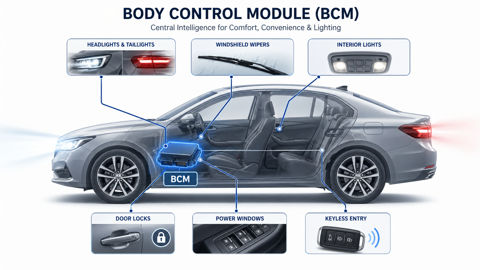
A body control module is an electronic control unit that manages many comfort, convenience, lighting, access, and body-related functions in a vehicle. It does not usually control engine combustion or transmission shifting. Instead, it coordinates systems such as power windows, door locks, interior lights, exterior lights, wipers, keyless entry, alarm functions, and sometimes parts of climate control or immobilizer logic.
What Is a Body Control Module?
A body control module, often shortened to BCM, is a vehicle electronic control unit responsible for managing body electronics. It receives input signals from switches, sensors, remote keys, door modules, and other ECUs. Then it processes those signals and sends commands to actuators, lights, motors, locks, and other electrical loads.
For example, when a driver presses the lock button on a key fob, the BCM receives the signal, verifies the command, communicates with other modules if needed, and then activates the door lock circuit. When a door opens, the BCM may turn on the interior light, send a door-open message to the instrument cluster, and monitor whether the alarm system should respond.
In modern vehicles, the BCM is usually connected to communication networks such as CAN, LIN, or other in-vehicle buses.
What Does a Body Control Module Do?
A body control module controls and coordinates many electrical functions that drivers use every day. These functions may look simple from the outside, but they require stable signal processing, software logic, and reliable PCB-level power control inside the module.
Common BCM-controlled functions include:
| Function Area | Typical BCM Role |
|---|---|
| Lighting | Controls interior lamps, headlights, turn signals, brake lights, fog lamps, and courtesy lights |
| Door system | Controls central locking, door ajar signals, trunk release, and sometimes power sliding doors |
| Window and mirror system | Coordinates power windows, mirror adjustment, mirror folding, and defrost signals |
| Wiper system | Manages windshield wipers, washer pumps, and intermittent wiper timing |
| Security system | Supports anti-theft alarm, keyless entry, immobilizer communication, and remote control logic |
| Cabin convenience | Controls seat memory, sunroof signals, interior dimming, and accessory power |
| Vehicle communication | Sends and receives data from other ECUs through CAN, LIN, or similar networks |
Instead of running separate hardwired circuits for every function, the vehicle can use network communication between modules. This improves design flexibility and allows more advanced features to be controlled through software.
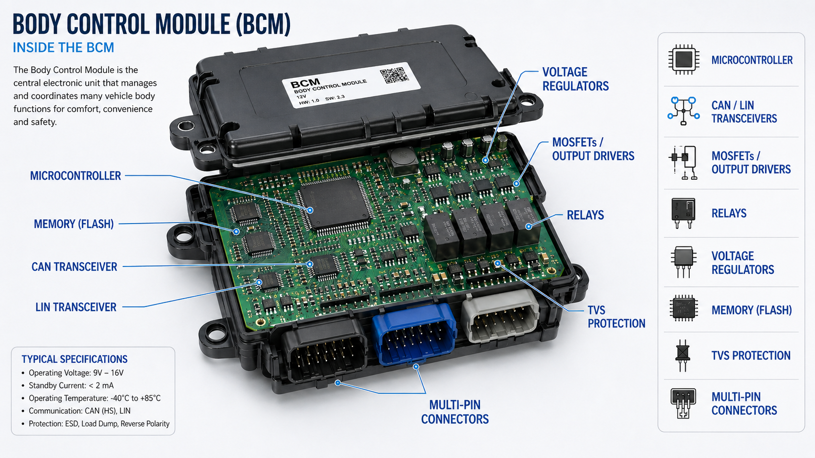
What Is Inside a Body Control Module PCB?
Inside a body control module, the PCB is the foundation of the entire system. It provides mechanical support, electrical connection, signal routing, power distribution, grounding, thermal paths, and communication integrity.
A typical body control module PCB may include:
| PCB/PCBA Element | Function |
|---|---|
| Microcontroller unit | Processes input signals and runs BCM software logic |
| Power management ICs | Regulate voltage for MCU, memory, communication circuits, and driver stages |
| CAN/LIN transceivers | Enable communication with other vehicle control modules |
| MOSFETs or relay drivers | Switch lamps, locks, motors, and other electrical loads |
| EEPROM or flash memory | Stores configuration, vehicle coding, fault data, or learned settings |
| TVS diodes and ESD protection | Protect circuits from voltage spikes and electrostatic discharge |
| Crystal oscillator | Provides timing reference for the microcontroller |
| Connectors | Link the BCM to vehicle wiring harnesses |
| Current sensing circuits | Monitor load condition, short circuits, or abnormal current |
| Relays or solid-state switches | Control higher-current body functions |
The PCB inside a BCM often uses FR-4 or high-Tg FR-4 material, depending on thermal and reliability requirements. In higher-reliability designs, the manufacturer may need controlled impedance routing, wider copper traces for power paths, stronger solder joint reliability, and protective coating against moisture or contamination.
How Does the PCB in a Body Control Module Control Vehicle Electronics?
The PCB in a body control module works as the electrical and logical platform for the whole unit. It routes low-voltage signals from switches and sensors to the microcontroller. It also carries higher-current paths that drive lights, locks, motors, and relays.
The process usually works like this:
1. Input detection
A switch, sensor, key fob receiver, or another ECU sends a signal to the BCM.
2. Signal conditioning
The PCB circuit filters noise, protects against surge voltage, and converts the signal into a level the microcontroller can read.
3. Software decision
The microcontroller checks the command, vehicle status, safety logic, and stored configuration.
4. Output driving
The BCM activates a MOSFET, relay, or driver IC to control the required load.
5. Network feedback
The BCM may send status information to the instrument cluster, gateway, alarm system, or diagnostic tool.
Because of this workflow, BCM PCB design must balance signal integrity, power integrity, EMC protection, thermal performance, and connector durability. A weak PCB layout may lead to unstable signals, false triggers, communication errors, or early component failure.
What Components Are Used in a Body Control Module PCBA?
A body control module PCBA uses both signal-level and power-level components. The exact design depends on the vehicle platform, OEM requirements, and electrical architecture.
Common components include:
Microcontroller
This is the main processing device. It runs firmware, reads input signals, controls outputs, manages diagnostics, and communicates with other modules.
CAN and LIN transceivers
These components allow the BCM to exchange information with the instrument cluster, door modules, gateway, engine ECU, HVAC module, and other control units.
MOSFETs and driver ICs
Many body loads require current switching. MOSFETs are often used for lamps, motors, solenoids, and lock actuators. Driver ICs improve control stability and protection.
Relays
Some BCM designs still use relays for certain high-current or isolated switching functions, although many newer designs use solid-state power devices.
Voltage regulators
The vehicle battery voltage is unstable compared with consumer electronics power rails. Regulators convert the input voltage into stable levels for ICs and logic circuits.
Protection devices
TVS diodes, ESD suppressors, fuses, current-limiting parts, and reverse-polarity protection are used to protect the PCBA from harsh automotive electrical events.
Connectors
BCM connectors must withstand vibration, insertion force, humidity, temperature cycling, and long-term vehicle use.
Passive components
Resistors, capacitors, inductors, and filters help stabilize signals, reduce noise, and support EMC performance.
For PCB assembly, component selection should consider AEC-Q qualification, temperature rating, traceability, long-term availability, and solder joint reliability.
Where Is the Body Control Module Located on a Car?
The body control module location depends on the vehicle brand, model, year, and architecture. It is commonly installed inside the cabin because it needs access to many interior wiring harnesses and body electronics.
Common BCM locations include:
| Possible Location | Why It Is Used |
|---|---|
| Under the dashboard | Close to switches, instrument panel, and cabin wiring |
| Behind the glove box | Protected location with space for module mounting |
| Driver-side kick panel | Near fuse box and body harness connections |
| Near the interior fuse box | Easy integration with power distribution |
| Center console area | Convenient for cabin electronics routing |
| Under a seat | Used in some vehicle platforms, but moisture protection becomes important |
The exact location should always be checked in the vehicle service manual. Removing trim panels without correct guidance may damage connectors, clips, or wiring harnesses.
How to Test a Body Control Module?
Testing a body control module should be systematic. Many symptoms that look like a bad BCM may actually come from a weak battery, blown fuse, damaged wiring, poor ground, water ingress, or a failed actuator.
A practical BCM testing process includes:
1. Check the battery and charging system
Low voltage can cause communication errors, false warning lights, and intermittent BCM behavior.
2. Inspect fuses and relays
A blown fuse may disable one function and make the BCM appear faulty.
3. Scan for diagnostic trouble codes
A professional scan tool can read BCM-related DTCs, communication errors, input status, and output commands.
4. Check power and ground at the BCM connector
The BCM needs stable battery feed, ignition feed, and ground. Voltage drop testing is useful here.
5. Inspect connectors and wiring harnesses
Look for corrosion, loose pins, bent terminals, water marks, burnt areas, or previous repair damage.
6. Test input and output functions
Use a scan tool to monitor switch inputs and command outputs such as locks, lights, and wipers.
7. Check network communication
CAN or LIN communication problems can make the BCM lose contact with other modules.
8. Confirm software coding or programming
Some BCMs need vehicle-specific programming after replacement. An unprogrammed module may not work correctly even if the hardware is good.
What Testing Is Required for Body Control Module PCB Assembly?
For body control module PCBA manufacturing, testing must be much more rigorous than ordinary consumer electronics testing. Automotive electronics operate under vibration, electrical noise, temperature variation, humidity, and long service life expectations.
Common BCM PCBA testing may include:
| Test Method | Purpose |
|---|---|
| AOI inspection | Checks solder joints, component placement, polarity, and missing parts |
| X-ray inspection | Inspects hidden solder joints under QFN, BGA, or other bottom-terminated components |
| ICT test | Verifies circuit connectivity, resistance, capacitance, and basic component values |
| Functional test | Confirms actual BCM input, output, communication, and control behavior |
| Programming test | Loads firmware and verifies successful MCU programming |
| CAN/LIN communication test | Confirms stable vehicle network communication |
| High-low temperature test | Evaluates operation under automotive temperature stress |
| Burn-in test | Screens early-life failures before shipment |
| Vibration-related validation | Helps verify solder joint and connector durability |
| Conformal coating inspection | Confirms coating coverage and protects against moisture or contamination |
A body control module PCB assembly should also follow strict traceability. Component lot numbers, PCB batch data, process records, test results, and repair history should be documented. This is especially important for automotive projects that require IATF 16949-based quality management.
What Causes a BCM to Fail?
A BCM can fail due to electrical, mechanical, environmental, software, or manufacturing-related factors. Since the BCM connects to many circuits, it is exposed to more risk than a simple single-function module.
Common causes include:
Water ingress
Moisture can corrode connectors, damage PCB traces, create leakage paths, and cause intermittent faults.
Voltage spikes
Load dump, jump-start mistakes, alternator problems, or poor grounding can create harmful voltage transients.
Short circuits in connected loads
A shorted lock actuator, lamp circuit, motor, or harness may overload BCM output drivers.
Connector corrosion
Even if the PCB is intact, poor connector contact can interrupt signals or power supply.
Solder joint fatigue
Thermal cycling and vibration can weaken solder joints over time, especially around large components and connectors.
PCB contamination
Flux residue, ionic contamination, or poor cleaning can reduce insulation resistance and create leakage issues.
Software or programming issues
Incorrect coding, failed updates, or incompatible replacement modules can cause abnormal behavior.
Manufacturing defects
Poor soldering, weak component placement, insufficient inspection, or unqualified components may shorten service life.
For PCB manufacturers, these failure causes show why automotive PCBA needs strong process control, stable materials, and complete test coverage.
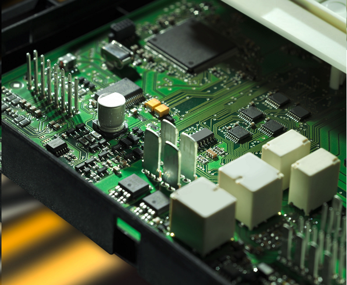
What Are Common PCB Failure Points in a Body Control Module?
Inside a body control module, several PCB areas are more vulnerable than others because they handle current, heat, vibration, or external wiring stress.
Common PCB failure points include:
| Failure Point | Possible Result |
|---|---|
| Connector solder joints | Intermittent power, ground, or signal loss |
| MOSFET output stage | Failed lights, locks, wipers, or motor control |
| Power regulation area | No communication, random reset, or complete module failure |
| CAN/LIN transceiver circuit | Communication loss with other ECUs |
| Protection components | Reduced surge protection after severe electrical events |
| Ground plane or power trace | Voltage drop, heating, or unstable operation |
| Relay solder joints | Intermittent output control |
| Contaminated PCB surface | Leakage current, false input signal, or corrosion |
Many BCM failures are not caused by the microcontroller itself. They often come from power supply instability, corroded connectors, damaged output drivers, poor solder joints, or PCB contamination.
What Happens When the Body Control Module Goes Bad?
When the body control module goes bad, the vehicle may show multiple electrical symptoms at the same time. Since the BCM manages many body functions, failure symptoms can appear unrelated at first.
Common bad BCM symptoms include:
- Power windows stop working or behave inconsistently
- Door locks fail, cycle randomly, or do not respond to the key fob
- Interior lights stay on, flicker, or fail to turn on
- Headlights, turn signals, or brake lights act abnormally
- Windshield wipers work at the wrong speed or fail to park correctly
- Alarm system triggers unexpectedly
- Keyless entry stops working
- Instrument cluster shows warning messages
- Battery drains overnight due to a module staying awake
- Vehicle fails to recognize the key in some systems
- Communication codes appear during scan tool diagnosis
One important point: these symptoms do not always prove the BCM itself is defective. A wiring fault, water-damaged connector, weak battery, or failed actuator can create similar problems. Proper diagnosis should come before replacement.
Why Is PCB Design Important for Body Control Module Reliability?
PCB design is critical in a body control module because the board must manage low-level logic signals and higher-current body loads in the same assembly. It must also survive automotive electrical noise, heat, humidity, vibration, and long working cycles.
Important BCM PCB design considerations include:
Power integrity
The PCB must distribute stable voltage to the microcontroller, communication ICs, memory, and output stages. Poor power routing may cause resets or unstable logic.
Grounding strategy
A strong ground design reduces noise, improves EMC behavior, and keeps sensing circuits stable.
Thermal design
MOSFETs, voltage regulators, and relays can generate heat. Copper area, thermal vias, and component spacing help control temperature rise.
EMC and EMI control
BCM circuits must avoid generating excessive interference and must resist external electromagnetic noise.
Protection design
Automotive PCBs need protection against ESD, surge, reverse polarity, load dump, and transient voltage events.
Connector reinforcement
Connectors face mechanical stress from harness movement and vibration. PCB pad design and solder joint quality are important.
Moisture protection
Conformal coating, solder mask quality, enclosure design, and cleanliness help reduce corrosion and leakage current.
A reliable BCM PCB is not only about connecting components. It is about creating a stable electrical platform for the complete vehicle body control system.
How Does Automotive PCBA Manufacturing Affect BCM Performance?
Automotive PCBA manufacturing has a direct influence on BCM performance because small process variations can become long-term reliability risks.
For example, insufficient solder paste may cause weak solder joints. Excessive voiding under power components may increase thermal resistance. Poor cleaning may leave ionic contamination on the PCB surface. Uncontrolled component sourcing may introduce parts with inconsistent quality or uncertain traceability.
For BCM projects, a capable automotive PCBA manufacturer should provide:
- Automotive-grade component sourcing
- PCB fabrication with stable material control
- Accurate SMT placement
- AOI and X-ray inspection
- Reflow profile control
- ICT and functional testing
- Firmware programming support
- Conformal coating when required
- Full traceability for components, PCB batches, and process data
- Engineering support for DFM, DFA, and DFT review
For vehicle electronics, the PCBA must be manufactured as a controlled engineering product, not just assembled as a common circuit board. This is especially important for BCMs because they connect to many user-facing and safety-adjacent vehicle functions.
How Much Does a BCM Cost to Replace?
The cost to replace a body control module depends on the vehicle model, module type, labor rate, programming requirement, and whether the part is new, remanufactured, or used. As a general market reference, RepairPal estimated the average BCM replacement cost at $666 to $725, with labor estimated at $115 to $169 and parts around $551 to $556. RepairPal also lists body control system diagnosis and testing at $49 to $72 on average. These ranges do not include taxes, fees, location differences, or related repairs.
How Do I Reset the Body Control Module?
A body control module reset may help in some cases, especially when the issue is caused by temporary software lockup or low-voltage confusion. However, resetting the BCM will not repair damaged hardware, corroded connectors, shorted circuits, or failed PCB components.
Common reset methods may include:
Battery disconnect reset
Some technicians disconnect the negative battery terminal for a period of time, then reconnect it. This may clear temporary module states in some vehicles.
Scan tool reset
A professional diagnostic tool may perform a BCM reset, relearn, or initialization procedure.
Fuse removal reset
In some vehicles, removing the BCM fuse for a short time may reset the module. This must be done according to the service manual.
Software relearn or programming
After replacement, the BCM may require coding, programming, immobilizer relearn, or key matching.
Before resetting a BCM, it is better to record diagnostic trouble codes. Clearing or resetting the module too early may erase useful diagnostic information.
For modern vehicles, always follow the OEM service procedure. Incorrect reset or programming may create more electrical problems.
How to Choose a Reliable Body Control Module PCB Manufacturer?
Choosing a reliable body control module PCB manufacturer requires more than checking price and lead time. BCM electronics are used in a demanding automotive environment, so the supplier should understand both PCB fabrication and automotive PCBA requirements.
A good BCM PCB or PCBA supplier should offer:
| Selection Factor | Why It Matters |
|---|---|
| Automotive experience | Helps avoid design and process risks specific to vehicle electronics |
| IATF 16949 quality mindset | Supports automotive process control and traceability |
| DFM review | Finds PCB manufacturability issues before production |
| DFT support | Improves test coverage and reduces hidden defects |
| Component traceability | Reduces counterfeit and lifecycle risks |
| Functional testing capability | Verifies real BCM behavior before shipment |
| Conformal coating process | Improves moisture and contamination resistance |
| Engineering communication | Helps solve layout, material, thermal, and assembly problems faster |
For BCM PCB projects, EBest PCB can support PCB fabrication, component sourcing, PCBA assembly, inspection, functional testing coordination, and engineering review. This is useful for automotive electronics teams that need one supplier to manage both circuit board quality and assembly reliability.
FAQs About Body Control Module
1. What is a body control module in simple words?
A body control module is a vehicle computer that controls many electrical body functions, such as lights, door locks, windows, wipers, keyless entry, and alarm systems.
2. Is the BCM the same as the ECU?
No. The BCM is one type of ECU, but it is not usually the engine ECU. The engine ECU controls engine operation, while the BCM controls many body and cabin electronics.
3. Can a bad BCM drain the battery?
Yes. A faulty BCM may keep circuits awake when the vehicle is parked. This can create parasitic current draw and drain the battery overnight.
4. Can a BCM be repaired instead of replaced?
Sometimes, yes. If the issue is caused by a damaged relay, solder joint, connector, or power component, repair may be possible. However, many professional workshops replace and program the module for reliability and warranty reasons.
5. Does a used BCM need programming?
In many vehicles, yes. A used BCM may need coding, immobilizer matching, key relearn, or software configuration before it works correctly.
6. What PCB material is used in a body control module?
Many BCM PCBs use automotive-grade FR-4 or high-Tg FR-4. The final material depends on thermal requirements, reliability targets, copper weight, operating environment, and OEM specifications.
7. Why does a BCM PCB need conformal coating?
Conformal coating helps protect the PCB against moisture, dust, flux residue risk, and corrosion. It is especially useful when the module may be exposed to humidity or condensation.
8. What is the most common BCM failure symptom?
There is no single symptom for all vehicles. Common signs include abnormal lights, failed locks, keyless entry problems, wiper issues, communication codes, and unexplained battery drain.
You may also like


Tags: Body Control Module, Body Control Module PCB, body control module symptoms