





Choosing the right soldering temperature is not as simple as setting an iron to one number and using it for every joint. For most electronics work, a soldering iron tip is commonly set somewhere around 315–350°C (599–662°F) for leaded solder and 340–370°C (644–698°F) for common lead-free solder. These are practical starting ranges rather than universal limits.
The correct setting also depends on solder alloy, PCB copper area, tip geometry, component size, flux activity, and how quickly the soldering station can replace lost heat. A small SMD pad may solder cleanly near the lower end of the range, while a connector tied to a large ground plane may need a larger tip, preheating, or a modest temperature increase.
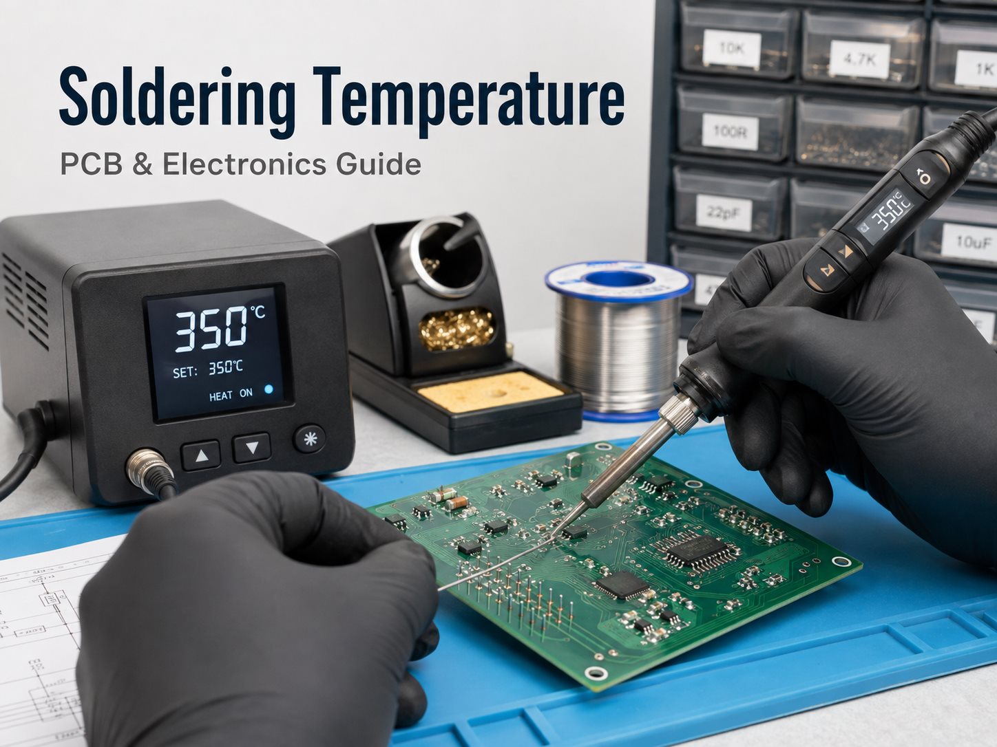
What Is the Best Soldering Temperature for Electronics?
For general electronics soldering, about 320–350°C is a useful starting range for leaded solder, while 340–370°C is more typical for lead-free solder.
The temperature should be high enough to heat the pad, component lead, and solder quickly, but not so high that flux burns away before the joint forms.
A practical starting point is:
- Fine electronic wiring or small pads: 300–330°C
- General PCB work with leaded solder: 320–350°C
- General PCB work with lead-free solder: 340–370°C
- Large connectors or high-copper areas: often near the upper end of the range, preferably with a larger tip or PCB preheating
The best soldering temperature is therefore the lowest setting that can bring the entire joint to soldering temperature within a short, controlled contact time.
If the iron must remain on the joint for a long time, simply using a lower temperature is not necessarily gentler. Extended heating can transfer more total energy into the PCB and component than a slightly hotter tip used briefly.
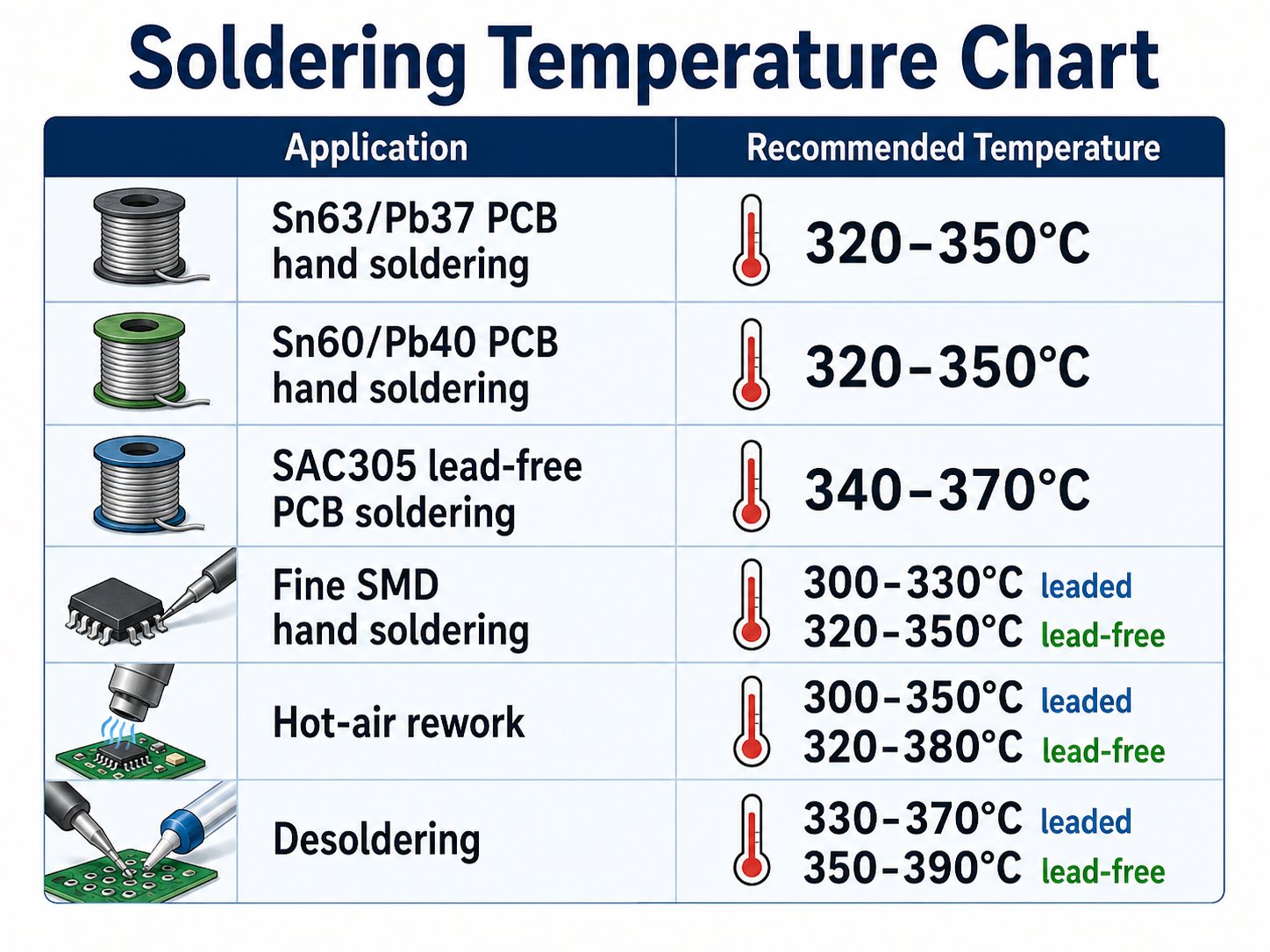
Soldering Temperature Chart for PCB and Electronics
The following soldering temperature chart provides practical starting values for common electronics work.
| Application | Solder / Process | Melting or Liquidus Temperature | Practical Starting Setting |
| General PCB hand soldering | Sn63/Pb37 | 183°C | 320–350°C |
| General PCB hand soldering | Sn60/Pb40 | About 183–190°C | 320–350°C |
| Lead-free PCB soldering | SAC305 | About 217–220°C | 340–370°C |
| Fine SMD hand soldering | Leaded | About 183°C | 300–330°C |
| Fine SMD hand soldering | Lead-free | About 217–220°C | 320–350°C |
| Large PCB connector | Leaded | About 183–190°C | 340–370°C* |
| Large PCB connector | Lead-free | About 217–220°C | 350–380°C* |
| Leaded hot-air rework | Process dependent | — | About 300–350°C display setting* |
| Lead-free hot-air rework | Process dependent | — | About 320–380°C display setting* |
| Leaded desoldering | SnPb | About 183–190°C | 330–370°C* |
| Lead-free desoldering | SAC-type alloy | About 217–220°C | 350–390°C* |
*These values depend strongly on thermal mass, equipment calibration, nozzle or tip size, airflow, and preheating.
The table should be treated as a setup reference rather than a process specification. The actual solder joint temperature is different from the temperature shown on the soldering station.
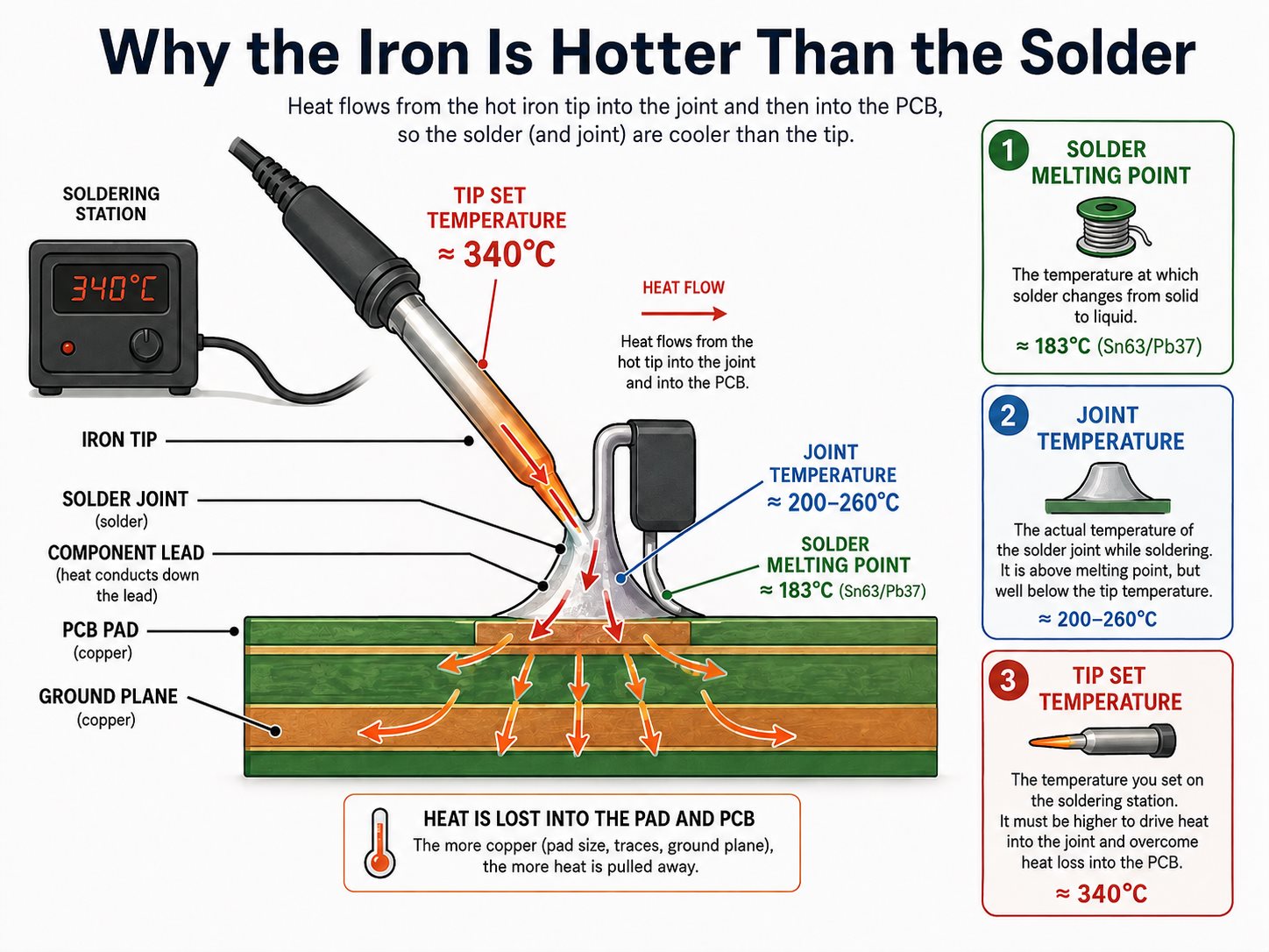
Why Is Soldering Iron Temperature Higher Than the Solder Melting Point?
A soldering iron is normally set far above the solder’s melting point because heat must travel from the heater through the tip and into the complete joint.
For example, Sn63/Pb37 solder melts at 183°C, but setting an iron to 183°C would usually provide very little thermal margin. As soon as the tip touches a copper pad, heat begins flowing into:
- the copper track,
- plated through-hole barrel,
- component lead,
- nearby copper planes,
- and the PCB laminate.
The tip surface can cool substantially during this transfer.
This is why melting temperature and soldering iron temperature are not interchangeable measurements.
Three temperatures are especially easy to confuse:
- Solder melting temperature: where the alloy changes state.
- Joint temperature: the temperature actually reached by the pad, lead, and solder.
- Tip set temperature: the value selected on the soldering station.
A good soldering station compensates quickly when the tip loses heat. A weak station may show 350°C on the display yet struggle on a large ground connection because its heater cannot restore tip temperature fast enough.
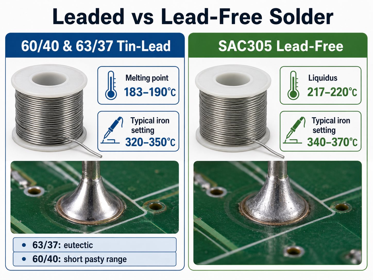
What Soldering Temperature Should You Use for 60/40 and 63/37 Solder?
For 60/40 and 63/37 tin-lead solder, approximately 320–350°C is a practical hand-soldering starting range for normal PCB work.
The two alloys behave slightly differently.
Sn63/Pb37 is eutectic. It changes from solid to liquid at approximately 183°C without a significant pasty range. This makes the joint relatively easy to form and inspect during hand soldering.
Sn60/Pb40 begins melting at approximately 183°C and becomes fully liquid at around 190°C. It passes through a short plastic or pasty range during cooling.
For both alloys:
- Small pads can normally use the lower end of the temperature range.
- Larger terminals may require 340–350°C or slightly more.
- Large ground planes should first be addressed with a larger tip or preheater rather than excessive temperature.
- Good flux activity can reduce the time required to achieve complete wetting.
The difference between 60/40 and 63/37 is important, but PCB thermal mass usually has a greater effect on the required iron setting.
What Is the Best Soldering Temperature for Lead-Free Solder?
For common lead-free electronics solder such as SAC305, 340–370°C is a practical starting range for hand soldering.
Lead-free solder typically has a higher melting temperature than traditional SnPb solder. SAC305, for example, has a liquidus temperature around 217–220°C.
However, its higher working temperature does not mean every lead-free joint should automatically be soldered at 380°C or 400°C.
A better approach is to start around 340–350°C and increase only when the joint cannot reach temperature quickly enough.
Lead-free soldering also benefits from:
- an appropriately sized chisel or bevel tip,
- a station with good thermal recovery,
- active flux,
- clean and well-tinned tip surfaces,
- and PCB preheating for large thermal masses.
Lead-free processes can oxidize tips faster, so continuously increasing temperature to compensate for a poorly wetted or oxidized tip usually makes the situation worse.
What Soldering Iron Temperature Should You Use for PCB Work?
For most PCB hand soldering, about 320–350°C for SnPb solder and 340–370°C for lead-free solder provides a useful starting window.
The PCB construction determines how much heat the joint absorbs.
A small pad on a standard two-layer FR-4 board may reach soldering temperature almost immediately. The same component lead connected to a multilayer ground plane can pull heat away from the tip much faster.
Pay particular attention to:
- Ground and power planes: internal copper spreads heat away from the joint.
- Heavy copper PCB: thicker copper requires more thermal energy.
- Large plated through-holes: the barrel conducts heat through the board thickness.
- Large connectors: metal housings and thick pins act as heat sinks.
- Thermal vias: arrays of vias can transfer heat into internal or opposite-side copper.
- Metal-core boards: heat can leave the soldering area rapidly.
When a PCB joint is difficult to solder, using a larger tip with better contact area is often more effective than immediately turning the station hotter.
What Is the Proper SMD Soldering Temperature?
For small SMD hand soldering, about 300–330°C for leaded solder and 320–350°C for lead-free solder is often sufficient when the tip size and flux are appropriate.
Small components have little thermal mass, so they normally do not require the same thermal input as a large connector.
For packages such as 0402, 0603, SOIC, or fine-pitch IC leads, temperature control matters because the pad area is small and repeated heating can weaken the pad-to-laminate bond.
For cleaner SMD work:
- Use a tip that matches the pad geometry.
- Apply flux before touching the joint.
- Keep contact time short.
- Avoid pressing the tip into the pad.
- Allow the joint to cool before repeated rework.
- Use hot air or controlled reflow methods when a package cannot be heated evenly with an iron.
A high temperature is not automatically faster if the tip is too small to transfer heat efficiently.
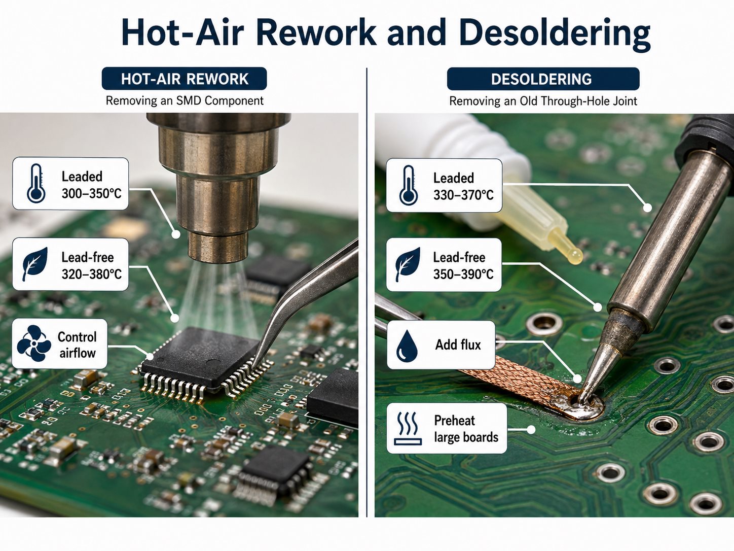
What Hot Air Soldering Temperature Should You Use for PCB Rework?
For PCB hot-air rework, roughly 300–350°C for leaded assemblies and 320–380°C for lead-free assemblies can be used as initial station settings, but airflow and PCB preheating are equally important.
A hot-air station does not behave like a soldering iron. The displayed temperature is the heater or calibrated air temperature, not necessarily the temperature at the solder joint.
Actual heating depends on:
- nozzle diameter,
- airflow,
- nozzle-to-board distance,
- component size,
- board thickness,
- copper distribution,
- surrounding components,
- and whether the PCB is preheated.
A thick multilayer PCB may require a higher displayed air temperature than a thin board, even when the target solder joint temperature is similar.
For large BGAs, QFNs, shielded modules, or high-copper boards, preheating the PCB reduces the temperature difference between the rework area and the rest of the board. This generally allows gentler top-side heating and reduces local thermal stress.
What Desoldering Temperature Should You Use?
For desoldering, about 330–370°C for leaded joints and 350–390°C for lead-free joints is a reasonable starting range, depending on board construction and the removal method.
Old solder can be more difficult to remove because of oxidation, contamination, or poor remaining flux activity.
Before raising the temperature, try:
- applying fresh flux,
- adding a small amount of fresh solder,
- using a wider desoldering tip,
- improving contact with the joint,
- preheating large multilayer boards,
- or using a powered desoldering tool for plated through-holes.
Adding fresh solder may seem counterintuitive, but it introduces active flux and improves heat transfer into an old joint.
Extra care is required on plated through-holes. Excessive temperature combined with prolonged heating can damage pad adhesion or the connection between the hole barrel and internal copper layers.
What Factors Change the Proper Soldering Temperature?
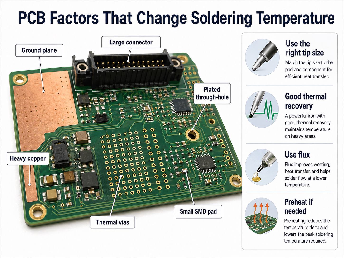
The proper soldering temperature is primarily determined by how efficiently heat moves from the tool into the solder joint.
The most important variables are:
- Solder alloy: lead-free alloys generally require higher process temperatures than SnPb alloys.
- Copper area: large pads, planes, and heavy copper remove heat rapidly.
- Tip geometry: a larger contact surface transfers energy more efficiently.
- Station power and recovery: higher heater capacity helps maintain tip temperature under load.
- Flux condition: active flux improves wetting and reduces the time needed to form the joint.
- Component thermal mass: connectors, switches, shields, and large terminals absorb more heat.
- PCB thickness: thick multilayer boards usually require more thermal energy.
- Preheating: raising the overall PCB temperature can reduce the heat demanded from the soldering tool.
- Contact time: temperature and dwell time must be considered together.
A station temperature therefore cannot be selected from solder alloy alone. Two assemblies using SAC305 may require noticeably different settings because one has small SMD pads while the other has a large connector tied to a power plane.
How Can You Tell If the Soldering Temperature Is Too High or Too Low?
The condition of the joint often shows whether the soldering temperature or heat-transfer setup needs adjustment.
| Temperature Too Low / Heat Transfer Too Weak | Temperature Too High / Heating Too Aggressive |
| Solder does not wet the pad easily | Flux burns or smokes excessively |
| Joint looks dull, uneven, or incomplete | Tip oxidizes quickly |
| Solder forms a ball instead of spreading | PCB surface discolors |
| Long contact time is required | Pads may loosen or lift |
| Large joints refuse to flow | Plastic connectors may deform |
| Excessive pressure is needed with the iron | Components experience unnecessary thermal stress |
A cold-looking joint does not always mean the temperature setting is too low. An oxidized tip, insufficient flux, a very small tip, or a large ground plane can produce similar symptoms.
Likewise, a joint that takes too long at 350°C may be improved by switching from a fine conical tip to a larger chisel tip instead of increasing the iron to 400°C.
FAQs About Soldering Temperature
Is 350°C too hot for PCB soldering?
No. Around 350°C is a common working temperature for many PCB soldering operations, particularly lead-free work or joints with moderate thermal mass. For small heat-sensitive pads, a lower setting may be more appropriate.
What is the normal soldering temperature for electronics?
A typical starting range is approximately 320–350°C for leaded solder and 340–370°C for lead-free solder. The final setting should be adjusted according to joint size, tip geometry, copper area, and contact time.
What temperature should I use for 60/40 solder?
For normal PCB hand soldering with Sn60/Pb40, start around 320–350°C. The alloy melts over approximately 183–190°C, but the iron must be hotter to transfer sufficient heat into the complete joint.
What temperature should I use for lead-free solder?
For common lead-free solder such as SAC305, around 340–370°C is a practical hand-soldering range. Large copper areas may require more thermal capacity, but a larger tip or preheater should usually be considered before using substantially higher temperatures.
Why won’t solder melt even when my iron is hot?
The tip may be oxidized, too small, poorly wetted, or unable to transfer enough heat into the joint. Large ground planes and connectors can also draw heat away faster than the soldering station can replace it.
Can too much heat lift PCB pads?
Yes. Excessive temperature, prolonged contact, repeated rework, and mechanical force can weaken pad adhesion and increase the risk of pad lifting. Controlled temperature, suitable tip geometry, flux, and short contact time reduce this risk.
How Can EBest Circuit Support Your PCB Assembly Project?
If you are preparing a PCB or PCBA project and need support with soldering process requirements, assembly manufacturability, or production planning, send your Gerber files, BOM, and assembly requirements to sales@bestpcbs.com. Our engineering team can review the project before production and help identify process conditions that may affect solder-joint quality, component reliability, or assembly yield.
You may also like



Tags: hot air soldering temperature, smd soldering temperature, soldering temperature, soldering temperature chart, soldering temperature for electronics