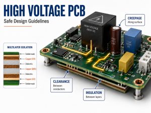
Choosing the right current sensor depends on more than the ampere range. Engineers also need to consider isolation, accuracy, bandwidth, response time, temperature drift, insertion loss, and PCB layout. These factors determine whether the sensor performs as expected once it is integrated into the final circuit.
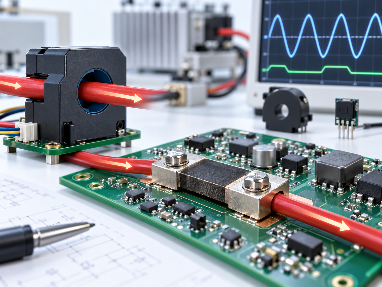
What Is a Current Sensor and What Does It Measure?
A current sensor detects the magnitude, and sometimes the direction, of current flowing through a conductor.
The measured current is converted into an electrical signal that can be read by a controller, ADC, protection circuit, or monitoring system. Depending on the sensor, the output may be analog, digital, current-based, or frequency-based.
Current sensors are commonly used for:
- Overcurrent protection
- Battery charge and discharge monitoring
- Motor current control
- Power measurement
- Load detection
- Power supply regulation
- Fault monitoring
A current sensor measures current, while a voltage sensor measures the potential difference between two points. In power-monitoring systems, both are often used together.
How Do Current Sensors Work?
Current sensors work by measuring either the voltage produced by current flow or the magnetic field created around the conductor.
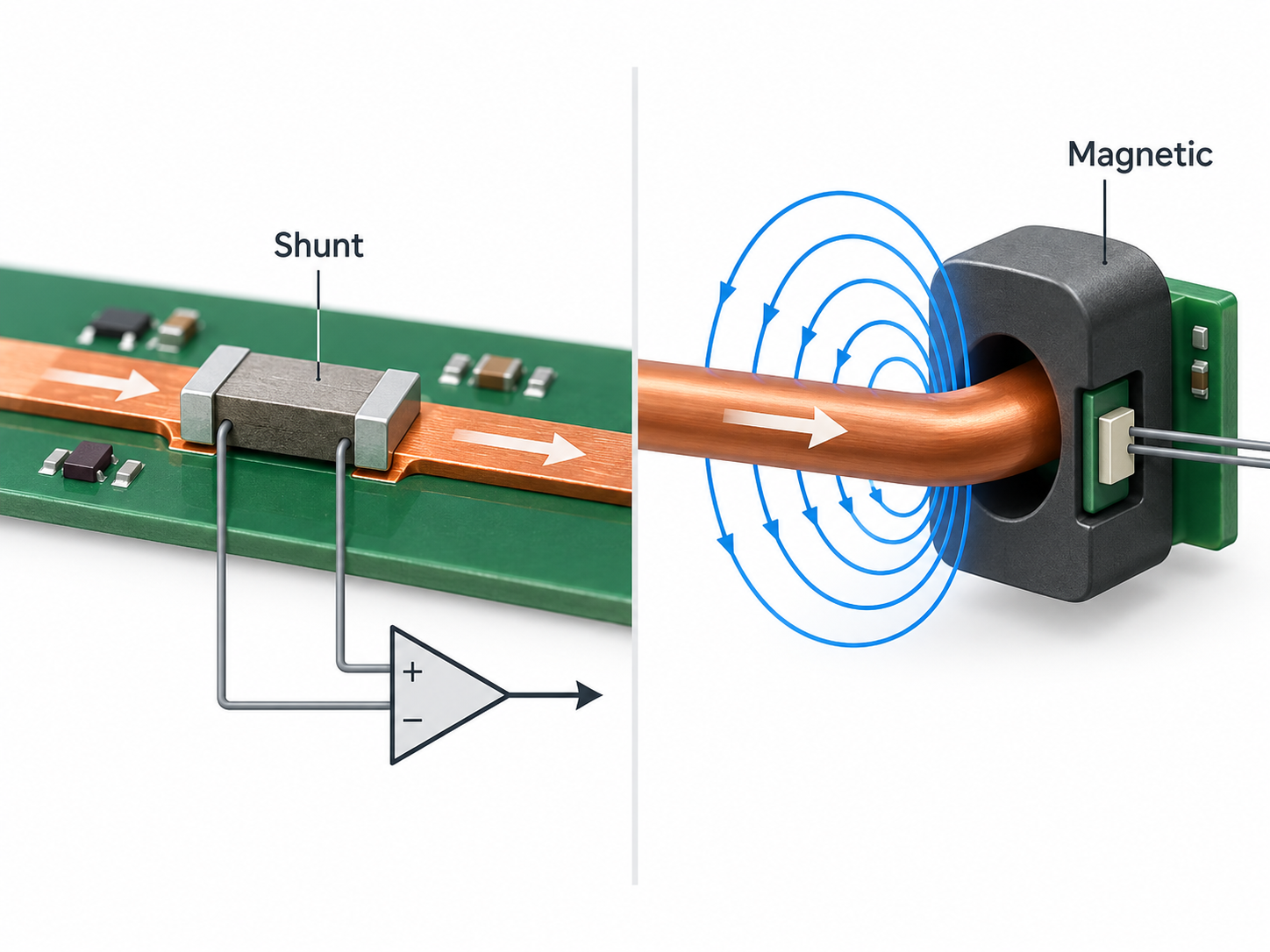
There are two basic sensing approaches.
Direct sensing
A low-value resistor is placed in series with the current path. The voltage across it follows Ohm’s law:
V = I × R
The circuit measures this voltage and calculates the current.
This approach is simple and accurate, but the resistor creates some power loss:
P = I²R
That loss becomes more important as current increases.
Magnetic sensing
Current flowing through a conductor creates a magnetic field. A magnetic current sensor detects this field without relying on a measurable voltage drop across a series resistor.
Common magnetic sensing methods include:
- Hall effect sensing
- Current transformers
- Rogowski coils
- Fluxgate sensing
- Magnetoresistive sensing
The sensing principle determines whether the device can measure AC, DC, or both.
What Are the Main Types of Current Sensors?
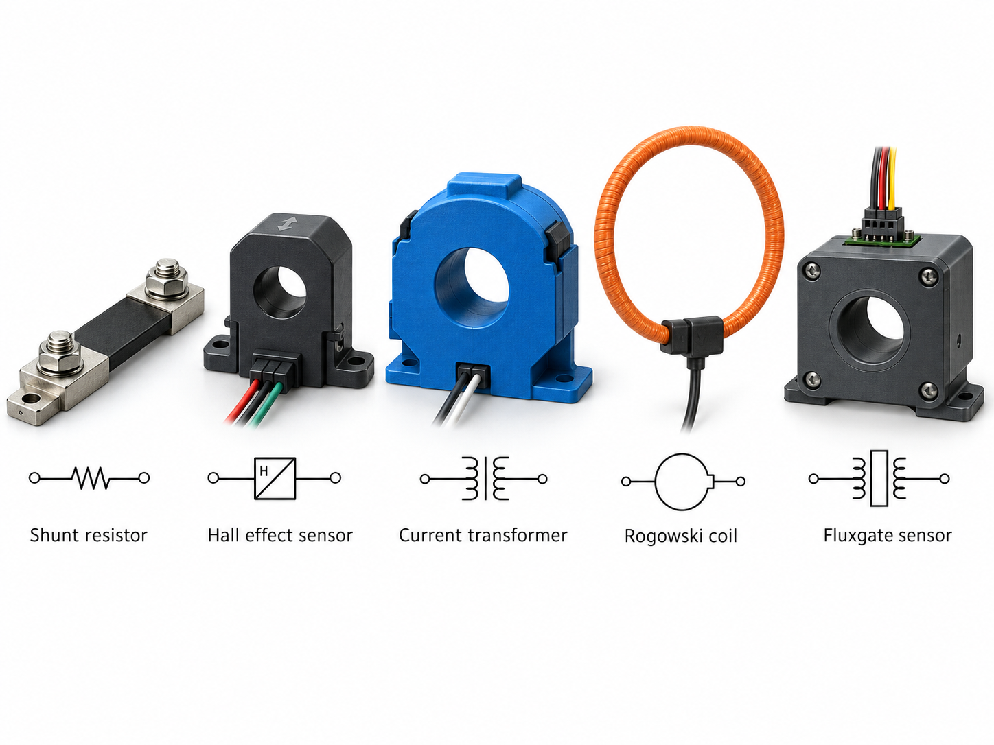
The main types of current sensors are shunt resistors, Hall effect sensors, current transformers, Rogowski coils, and fluxgate sensors.
| Current Sensor Type | AC | DC | Isolation | Main Advantage | Main Limitation |
|---|---|---|---|---|---|
| Shunt resistor | Yes | Yes | No inherent isolation | Accurate and simple | Power loss |
| Hall effect sensor | Yes | Yes | Available | AC/DC sensing with isolation | Offset and temperature drift |
| Current transformer | Yes | No | Yes | Efficient AC sensing | Cannot measure steady DC |
| Rogowski coil | Yes | No | Yes | Handles very high AC current | Requires signal integration |
| Fluxgate sensor | Yes | Yes | Yes | High DC accuracy | Higher cost and complexity |
Shunt resistor
A precision resistor creates a small voltage proportional to current. It is widely used in battery circuits, power supplies, and low-voltage power electronics.
Hall effect sensor
A Hall sensor measures the magnetic field around the conductor. It is widely used where AC/DC measurement and isolation are both required.
Current transformer
A current transformer reproduces AC current in a secondary winding. It is common in power monitoring, protection, and mains-connected equipment.
Rogowski coil
A Rogowski coil measures changing current without using a conventional magnetic core. It is well suited to high AC currents and fast current waveforms.
Fluxgate sensor
Fluxgate sensing is used when low offset, good linearity, and accurate DC measurement are important.
The correct type depends mainly on current waveform, isolation needs, accuracy, bandwidth, and current range.
How Do Hall Effect Current Sensors Work?
Hall effect current sensors measure the magnetic field generated by current flowing through a conductor.
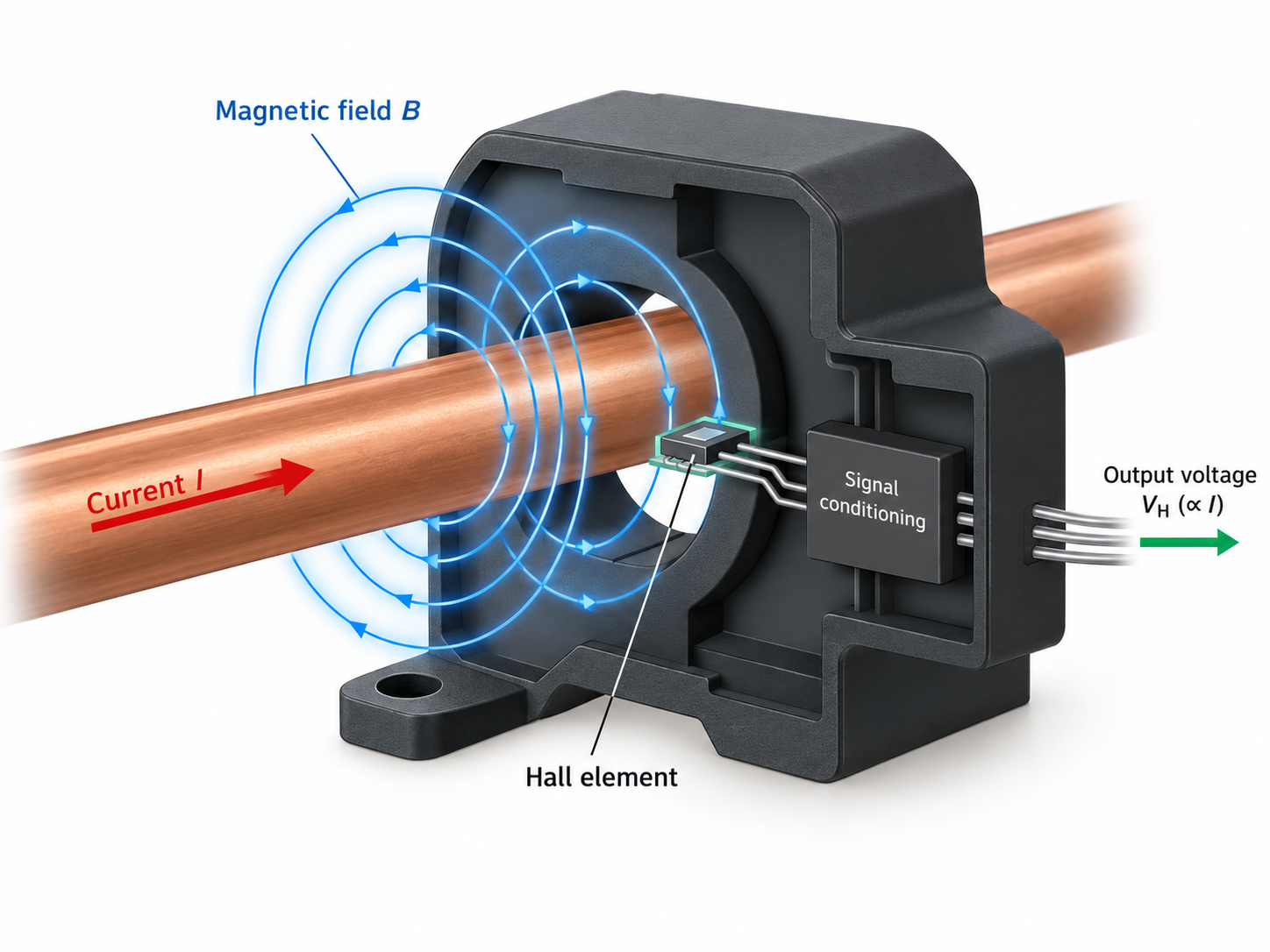
As current passes through the conductor, a magnetic field forms around it. A Hall element detects this field and produces a signal related to the magnetic flux density. Internal circuitry then amplifies and conditions the signal into a usable current measurement.
Hall sensors are commonly divided into two architectures.
Open-loop Hall sensors
These measure the magnetic field directly. They are relatively simple, compact, and cost-effective.
Closed-loop Hall sensors
These generate a compensation current that opposes the magnetic field from the primary conductor. The compensation current is then used as the measurement signal.
Closed-loop designs can provide better:
- Linearity
- Accuracy
- Response time
- Temperature stability
Hall effect current sensors can measure both AC and DC because the Hall element responds directly to magnetic field strength.
Integrated Hall current sensor ICs are widely used in PCB-mounted designs because the sensing element, signal conditioning, and current path can be combined in one package.
Which Current Sensors Can Measure DC Current?
Shunt resistors, Hall effect sensors, fluxgate sensors, and magnetoresistive sensors can measure DC current. Standard current transformers and Rogowski coils cannot measure steady DC.
| Sensor Type | DC | AC |
|---|---|---|
| Shunt resistor | Yes | Yes |
| Hall effect sensor | Yes | Yes |
| Fluxgate sensor | Yes | Yes |
| Magnetoresistive sensor | Yes | Yes |
| Current transformer | No | Yes |
| Rogowski coil | No | Yes |
For DC current sensing:
- Shunt resistors are simple and accurate but introduce resistance and heat.
- Hall effect sensors are useful when isolation and higher-current capability are required.
- Fluxgate sensors suit precision DC measurement where low offset and drift matter.
Current transformers cannot measure steady DC because they rely on changing magnetic flux. Rogowski coils have the same basic limitation and are therefore used for AC or transient current measurement.
What Specifications Matter When Choosing a Current Sensor?
The most important current sensor specifications are current range, AC/DC capability, accuracy, bandwidth, isolation, temperature drift, and output type.
The main parameters to check are:
- Current range: Include nominal current, peak current, startup current, and possible fault current.
- AC or DC capability: Confirm that the sensing principle supports the required waveform.
- Bidirectional sensing: Battery and regenerative systems often need positive and negative current measurement.
- Accuracy: Consider gain error, offset, nonlinearity, and noise.
- Bandwidth: Higher bandwidth is needed for switching converters, inverters, and fast control loops.
- Response time: Protection circuits may need very fast current detection.
- Isolation voltage: Check this carefully in high-voltage or mains-connected circuits.
- Temperature drift: Offset and sensitivity may change as temperature rises.
- Insertion loss: Shunt-based methods add resistance to the current path.
- Output type: Analog voltage, current output, PWM, SPI, I²C, and other interfaces are available.
- Package size: The package must suit the required current, thermal load, and PCB spacing.
A sensor with a suitable current range is not automatically the right choice. The total measurement error across temperature and operating conditions matters just as much.
Where Are Current Sensors Used?
Current sensors are widely used in systems that need to measure, control, or protect electrical power.
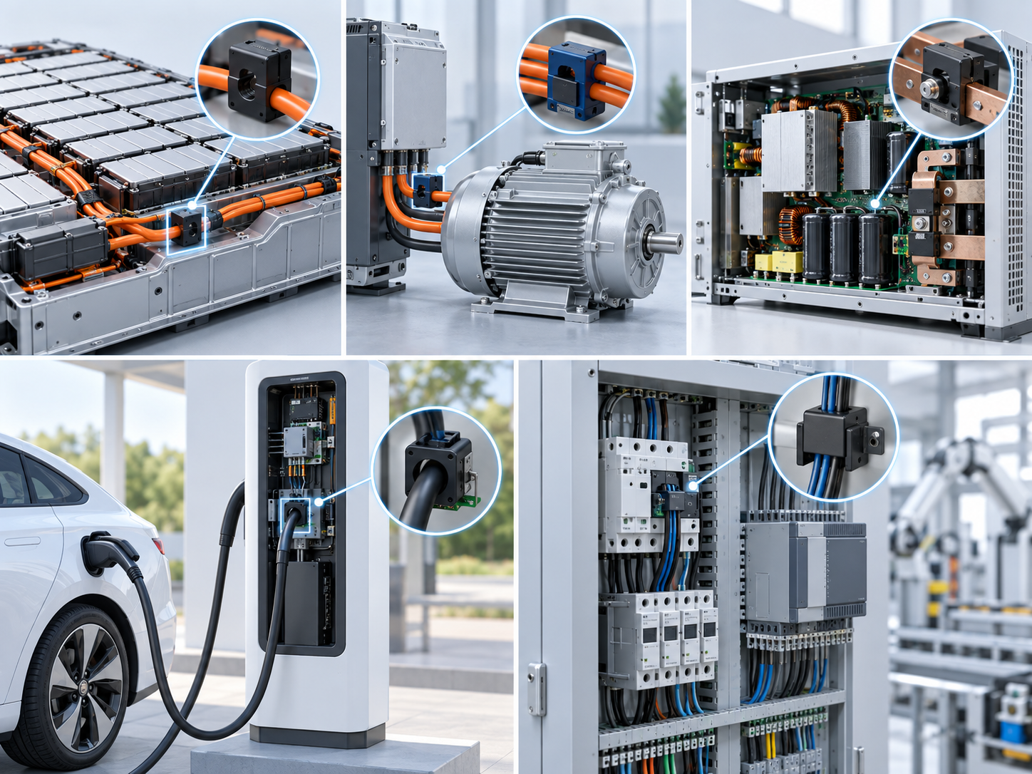
Typical applications include:
- Battery management systems: Measure charge and discharge current and support overcurrent protection.
- Motor drives: Monitor phase current for torque control, feedback, and fault protection.
- Power supplies: Support current regulation, current limiting, and output monitoring.
- Solar inverters: Measure current on DC input stages, conversion stages, or AC output.
- Energy storage systems: Track bidirectional battery current during charging and discharging.
- Industrial equipment: Detect overloads, abnormal loads, and changes in machine operation.
- EV charging systems: Monitor power conversion and charging current.
Different current sensors may be used within the same product because low-current control circuits and high-current power stages often have different requirements.
How Does PCB Design Affect Current Sensor Accuracy?
PCB layout can directly affect current sensor accuracy through trace resistance, heat, magnetic interference, grounding, and signal routing.
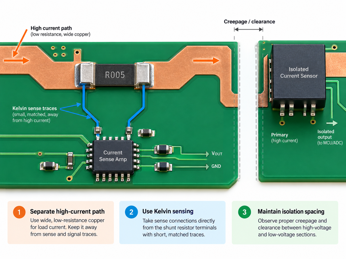
For shunt-based current sensing, Kelvin connections are especially important. The sense traces should measure voltage directly across the shunt rather than including voltage drops from the high-current copper path.
Good shunt layout usually includes:
- Separate Kelvin sense traces
- Short differential routing to the amplifier
- Minimal coupling from switching nodes
- Controlled high-current copper paths
- Careful ground routing
- Limited temperature gradients around the shunt
Hall effect sensors have a different set of layout concerns.
Nearby magnetic fields from components such as these can distort the measurement:
- Inductors
- Transformers
- Busbars
- High-current PCB traces
- Adjacent power conductors
For isolated current sensors, PCB creepage and clearance must also be maintained around the isolation barrier. Vias, copper pours, test pads, and nearby components should not reduce the intended spacing.
How Do You Choose the Right Current Sensor for Your Circuit?
Choose a current sensor by matching the sensing technology to the current waveform, isolation requirement, current range, accuracy, and response speed.
A practical selection process starts with five questions.
1. Do you need AC, DC, or both?
For DC or bidirectional current, common options include:
- Shunt resistor
- Hall effect sensor
- Fluxgate sensor
- Magnetoresistive sensor
For AC-only measurement, current transformers and Rogowski coils are also available.
2. Do you need galvanic isolation?
If the control circuit must be electrically separated from the power path, isolated Hall, current transformer, Rogowski, or fluxgate solutions are more suitable.
3. What is the maximum current?
Do not design around nominal current alone. Include:
- Startup current
- Motor stall current
- Regenerative current
- Switching peaks
- Fault current
4. How much accuracy and bandwidth are required?
Energy metering, battery monitoring, motor control, and overcurrent protection all have different measurement requirements.
5. Can the PCB support the sensor properly?
Check:
- Current-carrying copper
- Thermal rise
- Isolation spacing
- Magnetic interference
- Shunt routing
- Package footprint
A useful starting comparison is:
| Requirement | Common Starting Point |
|---|---|
| Low-cost AC/DC sensing | Shunt resistor |
| Isolated AC/DC sensing | Hall effect sensor |
| High-current AC sensing | Current transformer |
| Very high AC current | Rogowski coil |
| Precision isolated DC sensing | Fluxgate sensor |
| Compact PCB-level sensing | Integrated current sensor IC |
The final choice should meet the complete system requirement rather than simply matching the current rating.
FAQ About Current Sensors
1. What are the main types of current sensors?
The main types are shunt resistors, Hall effect sensors, current transformers, Rogowski coils, and fluxgate sensors. They differ in AC/DC capability, isolation, accuracy, bandwidth, and current range.
2. Can a current sensor measure both AC and DC?
Yes. Hall effect, shunt, fluxgate, and magnetoresistive sensors can measure both AC and DC. Standard current transformers and Rogowski coils cannot measure steady DC.
3. What is a Hall effect current sensor?
A Hall effect current sensor measures the magnetic field generated by current flowing through a conductor. It can measure AC and DC and can provide galvanic isolation.
4. What is the difference between a current sensor and a current transformer?
A current transformer is one type of current sensor used mainly for AC measurement. Current sensor is a broader term that also includes Hall, shunt, Rogowski, fluxgate, and other sensing methods.
5. What is the difference between a current sensor and a voltage sensor?
A current sensor measures current flowing through a conductor. A voltage sensor measures the electrical potential difference between two points.
6. Can current sensors be used with Arduino?
Yes. Current sensors with a compatible analog or digital output can connect to Arduino boards. Check the sensor’s supply voltage, output range, interface, and maximum current before use.
Ready to Review Your Current-Sensing PCB or PCBA?
Current sensor performance can be affected by high-current routing, Kelvin connections, copper thickness, isolation spacing, heat, and component placement. These details are easier to correct during PCB review than after assembly.
EBest Circuit supports PCB fabrication and PCBA for battery systems, motor drives, industrial controls, power supplies, chargers, and other current-sensing applications. Send your Gerber files, BOM, stackup, current requirements, and assembly specifications to sales@bestpcbs.com for DFM and manufacturing review.