BCM most often means Body Control Module in an automotive context. It is an electronic control unit that reads switches, sensors, and vehicle-network messages, runs body-control logic, and drives loads such as lamps, door locks, windows, mirrors, wipers, and interior convenience systems.
A BCM is not just a processor board. Its PCB must place low-voltage logic, vehicle communications, protected power inputs, and higher-current load drivers in one compact assembly while handling electrical transients, heat, electromagnetic interference, vibration, and long service life. This guide opens the module and follows the signal path from an input to a physical vehicle function.

What Is a BCM on a Car?
A BCM on a car is the electronic control unit responsible for body and convenience functions rather than combustion, traction, or transmission control. The exact boundary varies by vehicle: one platform may use a central BCM, while another divides the same work among front, rear, door, or zone controllers.
The search phrase what is a bcm module usually refers to the same device. “Module” describes the complete unit: the populated PCB, connector interface, housing, firmware, and calibration data. Replacing only the circuit board may not restore operation if the vehicle also requires coding, key matching, or configuration.
| Module | Primary responsibility | Typical inputs and outputs |
| BCM | Body, access, lighting, and cabin convenience functions | Door switches, locks, lamps, windows, mirrors, wipers, network messages |
| ECM | Engine operation | Engine sensors, fuel injection, ignition, emissions actuators |
| PCM | Powertrain control; on some vehicles it combines engine and transmission control | Engine and transmission sensors, injectors, ignition, shift control |
BCM, ECM, and PCM names are not perfectly standardized across automakers. The vehicle service information and electrical architecture remain the authority for a specific model.
What Does a BCM Control in a Car?
A BCM commonly controls exterior and interior lights, central locking, power windows, mirrors, wipers, washers, retained accessory power, and selected heaters or motors. It also coordinates these functions with door modules, gateways, and other ECUs when the vehicle architecture distributes the load control.
- Exterior lighting: headlamps, daytime running lamps, turn indicators, brake lamps, and welcome-light sequences.
- Access: central locking, keyless-entry requests, trunk or tailgate release, and anti-theft status exchange.
- Doors and glass: window motors, mirror fold or heating, door-ajar inputs, and child-lock functions.
- Wipers and washers: stalk requests, intermittent timing, rain-sensor messages, and pump or motor control.
- Cabin functions: interior lamps, retained accessory power, seat or steering-wheel heaters, and wake/sleep coordination.
Not every vehicle assigns every function to the BCM. Some loads are driven by door or zone modules after receiving BCM commands over CAN or LIN; the model-specific wiring diagram identifies the responsible controller and output stage.
How Does a BCM Work?
A BCM works through five blocks: it receives an input, protects and conditions the signal, evaluates the request in a microcontroller, commands a driver, and monitors the resulting load. For example, a door-switch transition can be debounced by the input circuit, interpreted by firmware, transmitted to another ECU if required, and used to switch a courtesy lamp through a protected high-side output.
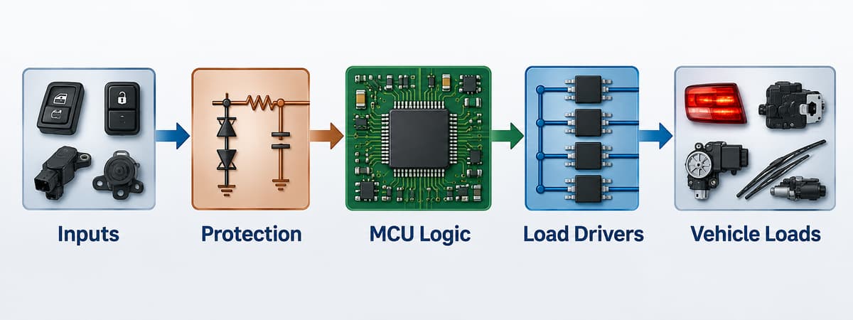
The complete path normally includes:
- Input acquisition: switches, Hall sensors, analog sensors, and messages from CAN or LIN nodes.
- Protection and conditioning: filtering, voltage clamping, reverse-polarity protection, level shifting, and transient-tolerant interfaces.
- Decision logic: an MCU applies timing, state-machine, safety, diagnostic, and energy-management rules.
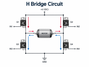
- Load actuation: smart high-side switches, low-side drivers, half bridges, full bridges, or relays operate lamps, heaters, solenoids, and motors.
- Feedback: current sense, fault flags, temperature status, position signals, and bus messages confirm whether the command succeeded.
Sleep behavior is another core function. When the vehicle is parked, the BCM must reduce its own current and coordinate network sleep without missing legitimate wake events such as a key request or door opening.
What Is Inside a BCM Module?
Inside a BCM module are a microcontroller, regulated power rails, CAN or LIN transceivers, protected input circuits, load drivers, nonvolatile memory, clocks, connectors, and thermal paths. Exact parts depend on the vehicle architecture, but real automotive reference designs make the functional split concrete.
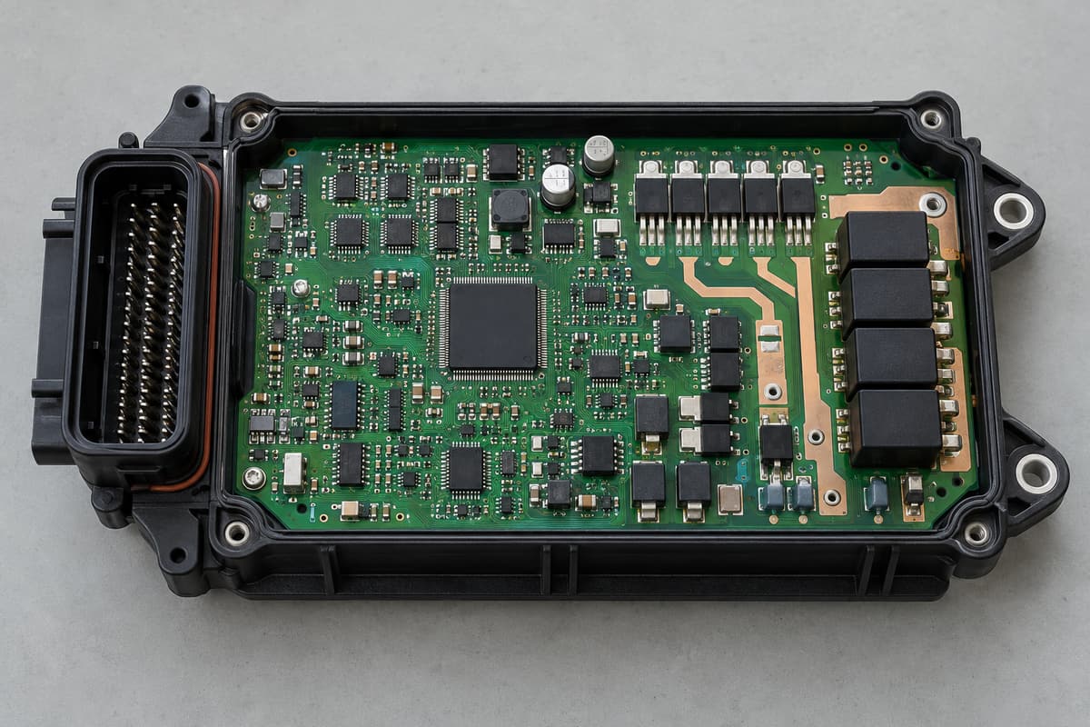
| Circuit function | Representative automotive device | Role in a BCM-class design |
| Microcontroller | TI AM263P4-Q1 | Runs control logic, diagnostics, timing, and network software in a recent zone-controller reference design |
| Power-management IC | TI TPS65386x-Q1 family | Generates and supervises regulated rails for the processor and peripheral circuits |
| CAN/CAN FD transceiver | TI TCAN1043A-Q1 | Converts MCU logic-level data to the differential vehicle bus and supports wake/sleep behavior |
| LIN transceiver | TI TLIN1021A-Q1 | Connects lower-cost local nodes such as switches, small actuators, or door electronics |
| Smart high-side switch | TI TPS1HC30-Q1 | Switches a protected body load and provides diagnostic feedback |
| Motor driver | TI DRV8245S-Q1 | Controls bidirectional DC loads such as selected window, latch, or seat mechanisms |
These are examples, not a universal BCM bill of materials. A more integrated approach is also possible: Infineon’s TLE9560-3QX system basis chip combines a 5 V regulator, CAN FD and LIN communication, two half-bridge drivers, high-side outputs, and SPI control in one device. The final choice depends on current, channel count, diagnostic coverage, thermal limits, software architecture, and the automaker’s component requirements.
How Does a BCM Communicate With Other ECUs?
A BCM communicates with other ECUs through vehicle networks, most commonly CAN or CAN FD for coordinated control and LIN for lower-cost local devices. Some newer centralized or zonal architectures also use automotive Ethernet for higher-bandwidth links, but not every BCM includes every interface.
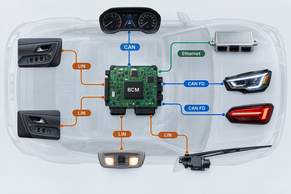
- CAN: robust multi-node communication for status, commands, diagnostics, and coordination among body, gateway, powertrain, and instrument modules.
- CAN FD: retains CAN arbitration while allowing a larger payload and faster data phase when the network and transceivers support it.
- LIN: a lower-cost single-master network suited to local switches, small motors, lighting nodes, and door electronics.
- Automotive Ethernet: a higher-bandwidth link increasingly associated with gateways and zone controllers rather than a universal requirement for conventional BCMs.
The PCB must keep these communication paths away from noisy switching nodes, preserve their return paths, and implement the termination, common-mode filtering, ESD protection, and connector pinout required by the actual interface design.
What Makes a BCM PCB Different From a General Control Board?
A BCM PCB differs from a general control board because it combines battery-connected power, sensitive digital logic, network interfaces, and multiple switched loads in a harsh electrical and mechanical environment. A circuit that works on a bench can still fail in a vehicle if the layout cannot handle a load dump, inductive switching, reverse battery, ground offset, thermal cycling, or conducted and radiated noise.
- Power partitioning: battery inputs, regulators, high-current outputs, logic rails, and communication grounds require a deliberate placement and return-path strategy.
- Current and heat: copper width, copper weight, via arrays, thermal spreading, connector pins, and driver packages must be checked against actual current and ambient temperature.
- Transient protection: suppressors, filters, reverse-polarity circuits, and protected drivers must be placed so surge current does not flow through the logic-ground path.
- EMC control: fast driver edges, motor currents, and DC/DC converters must not corrupt CAN, LIN, crystal, reset, or sensor signals.
- Mechanical reliability: connector insertion force, mounting points, enclosure support, vibration, moisture exposure, and coating keep-outs affect the PCB layout and assembly process.
Standard FR-4 PCB manufacturing may suit many body-control designs, but “FR-4” alone does not define a finished material system. The laminate grade, glass-transition temperature, CAF performance, copper construction, solder mask, coating, and validation plan should be matched to the specified environment rather than chosen from a generic layer-count rule.
Which PCB and PCBA Checks Matter for BCM Hardware?
The most important checks are power-path verification, network-layout review, assembly inspection, programming control, and functional testing under representative loads. They should be agreed before the design is released because a fixture, connector breakout, firmware image, or diagnostic interface may affect both PCB layout and production cost.
- PCB review: confirm stackup, copper weight, high-current trace temperature rise, thermal vias, creepage and clearance, test-point access, connector support, and coating keep-outs.
- Signal-integrity and EMC review: examine CAN/CAN FD differential routing, LIN protection, clock and reset nets, switching loops, power-plane discontinuities, and return-current paths.
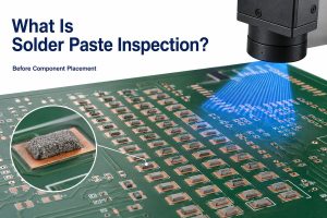
- Assembly controls: use solder paste inspection where applicable, AOI for visible joints, and X-ray for hidden-pad packages or thermal-pad voiding when required by the design.
- Programming and traceability: control firmware version, calibration data, serial or lot records, approved component alternatives, and the relationship between each assembly and its test result.
- Functional testing: exercise wake/sleep behavior, CAN and LIN communication, input thresholds, load outputs, current sensing, fault reporting, and quiescent current with defined limits.
A capable PCB assembly process should connect inspection records to the released BOM, placement data, firmware, and test procedure. Our quality and inspection overview explains the broader controls available for PCB and PCBA projects; the exact automotive test matrix still needs to be defined by the customer’s product requirements.
FAQ About BCM Hardware
Is a BCM the same as an ECU?
A BCM is one type of ECU. “ECU” is the broad category for electronic control units; “BCM” identifies the unit assigned to body and convenience functions.
Can one car have more than one BCM?
Yes. A vehicle can distribute body functions across a central BCM, door modules, a smart junction box, gateway, or front and rear zone controllers. The physical module count depends on the electrical architecture.
Does every BCM use CAN and LIN?
No. CAN is common, and LIN is widely used for local low-cost nodes, but the actual mix can include CAN FD, Ethernet, direct hardwired inputs, or proprietary interfaces.
Can a BCM switch loads without mechanical relays?
Yes. Smart high-side or low-side semiconductor switches can replace some relays and add current sensing, short-circuit protection, and diagnostic feedback. Relays may remain where load, isolation, cost, or fail-safe requirements favor them.
Why does a BCM need low sleep current?
The BCM remains connected to the vehicle battery while parked. Excess quiescent current can discharge the battery, so the design must place the MCU, transceivers, regulators, and output drivers into defined low-power states while preserving valid wake sources.
Where can I find BCM failure and reset information?
For symptoms, test methods, common failure causes, reset considerations, and repair-oriented questions, read our separate guide to Body Control Module testing and failure symptoms. Keeping that troubleshooting topic separate avoids mixing service procedures with this hardware-architecture guide.
How Can We Support Your BCM PCB and PCBA Project?
We can manufacture and assemble customer-released BCM and automotive control-board designs, with engineering review focused on manufacturability, stackup, materials, component availability, assembly, inspection, and test preparation. At EBest Circuit, our listed quality certifications include ISO 9001:2015 and IATF 16949; we confirm the applicable facility, process scope, and project requirements before quotation.
Our support can combine PCB fabrication, component sourcing, SMT and through-hole assembly, AOI, X-ray inspection where applicable, and functional-test coordination. Send your Gerber files, BOM, pick-and-place data, stackup or copper requirements, quantities, coating specification, firmware instructions, and test limits to sales@bestpcbs.com. We will review the package against the required automotive environment instead of treating it as a generic control board.