PCB manufacturing PCB manufacturing
Home > Blog

104J Capacitor Value, Code and Uses Explained

June 15th, 2026

104J capacitor is a capacitor marked with the code “104J,” which usually means it has a capacitance value of 100,000 pF, or 100 nF, or 0.1 µF, with a J tolerance of ±5%. This guide explains the 104J capacitor value, code meaning, unit conversion, material types, voltage ratings, common uses, replacement rules, and testing methods in a clear and practical way.

If you are checking an old circuit board, reading a capacitor marking, repairing an electronic device, or choosing a replacement part, the marking “104J” can be confusing at first. The good news is that this code follows a simple rule. Once you understand how to read it, you can quickly identify what a 104J capacitor does and whether it fits your circuit.

Here is the quick answer before we go deeper:

MarkingCapacitanceToleranceCommon Unit
104J100,000 pF±5%0.1 µF / 100 nF

In short, a 104J capacitor is most commonly a 0.1 µF capacitor. The “104” tells you the capacitance value, while the “J” tells you the tolerance.

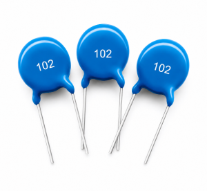
104J Capacitor

What Is a 104J Capacitor?

A 104J capacitor is an electronic component used to store and release electrical energy in a circuit. It is commonly used for decoupling, bypassing, filtering, noise suppression, coupling, timing, and general signal conditioning.

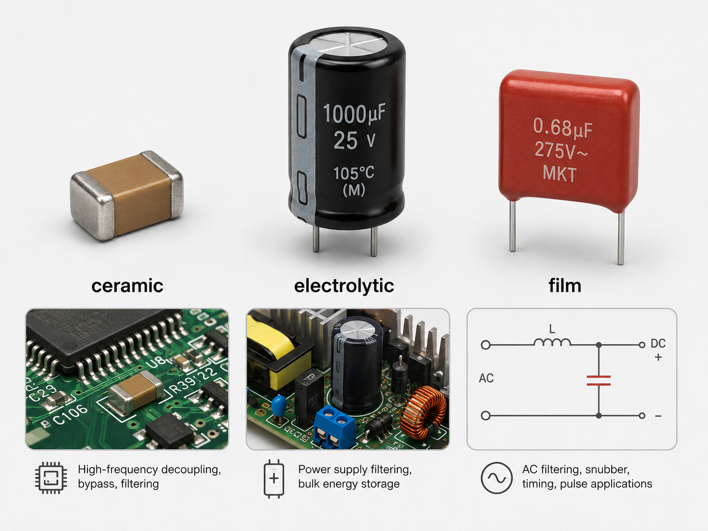
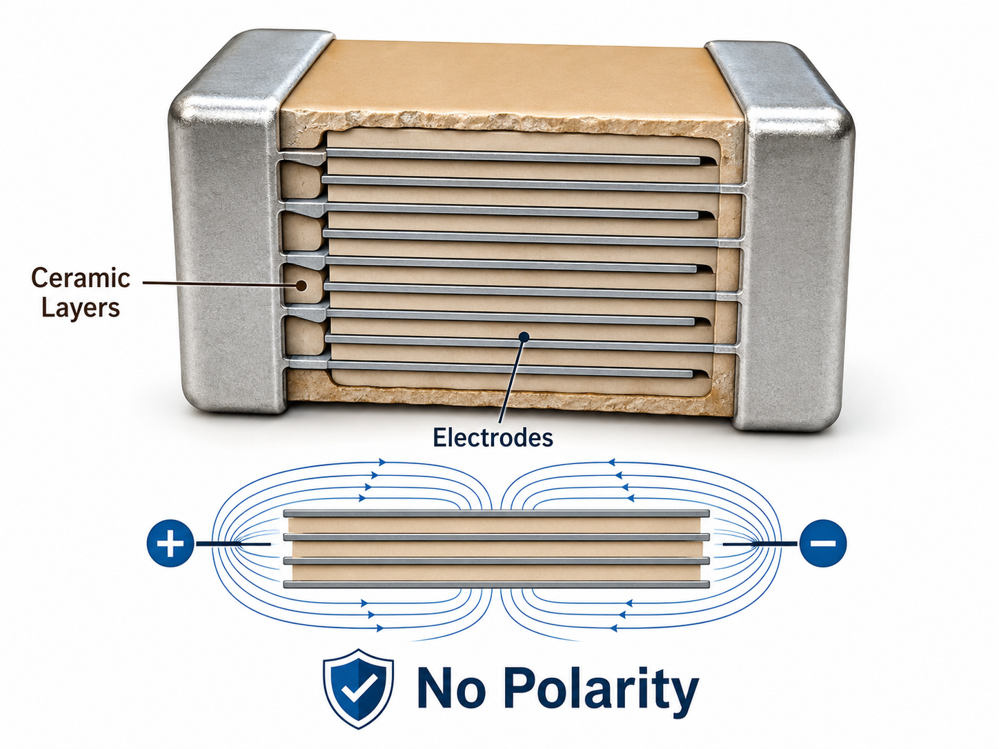
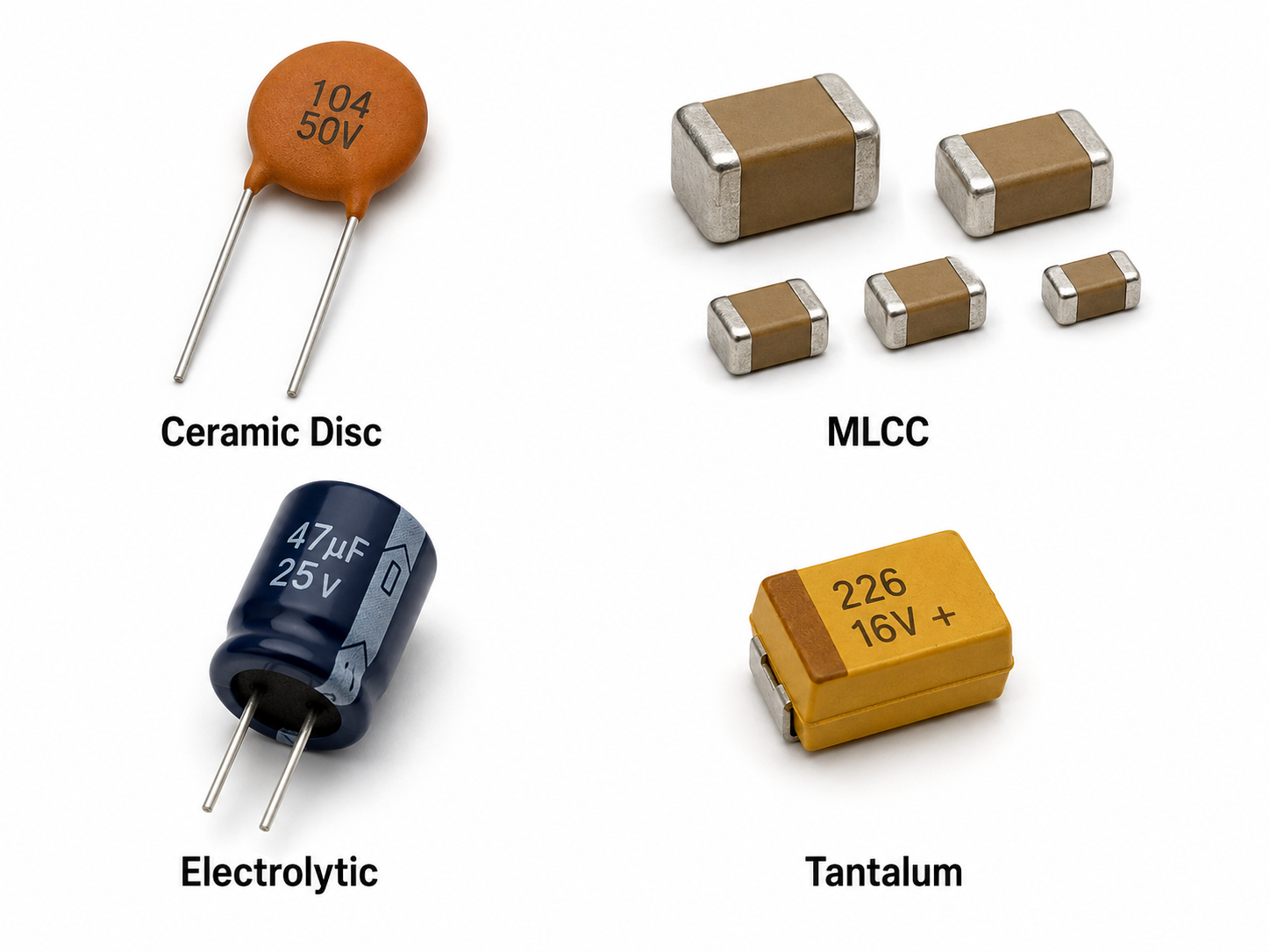
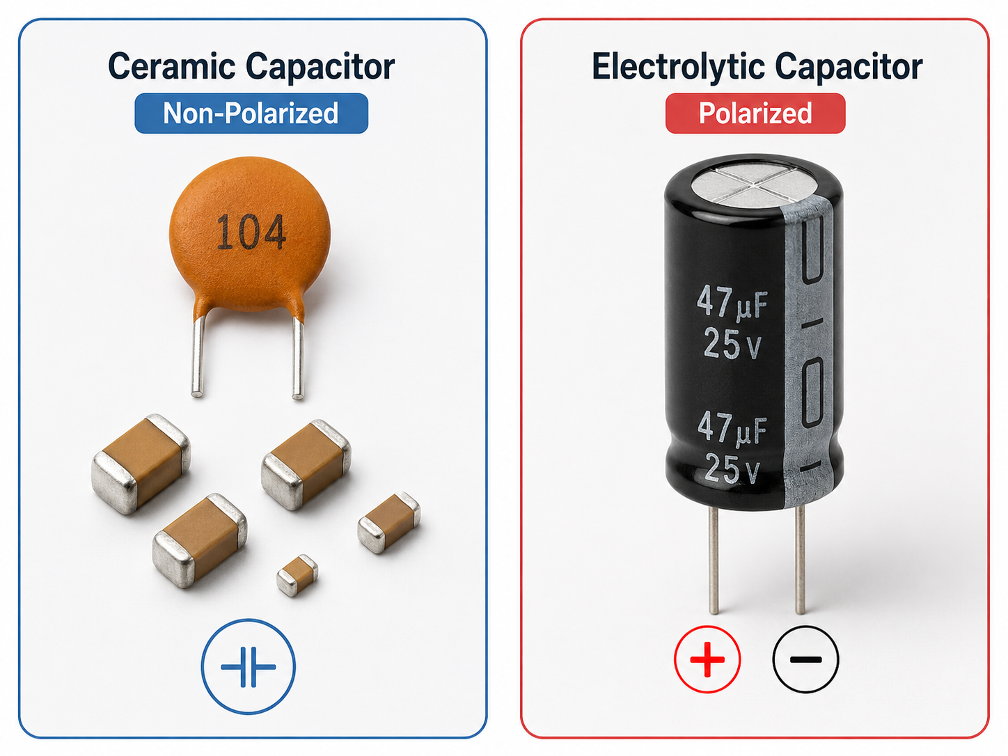
The marking “104J” appears on many capacitor types, especially ceramic capacitors and film capacitors. In many practical circuits, a 104J capacitor is selected because 0.1 µF is a very common capacitance value.

A 104J capacitor may appear in:

  • Power supply filter circuits
  • PCB decoupling networks
  • Audio circuits
  • Motor control circuits
  • LED driver circuits
  • Consumer electronics
  • Industrial control PCB boards
  • Automotive electronic modules

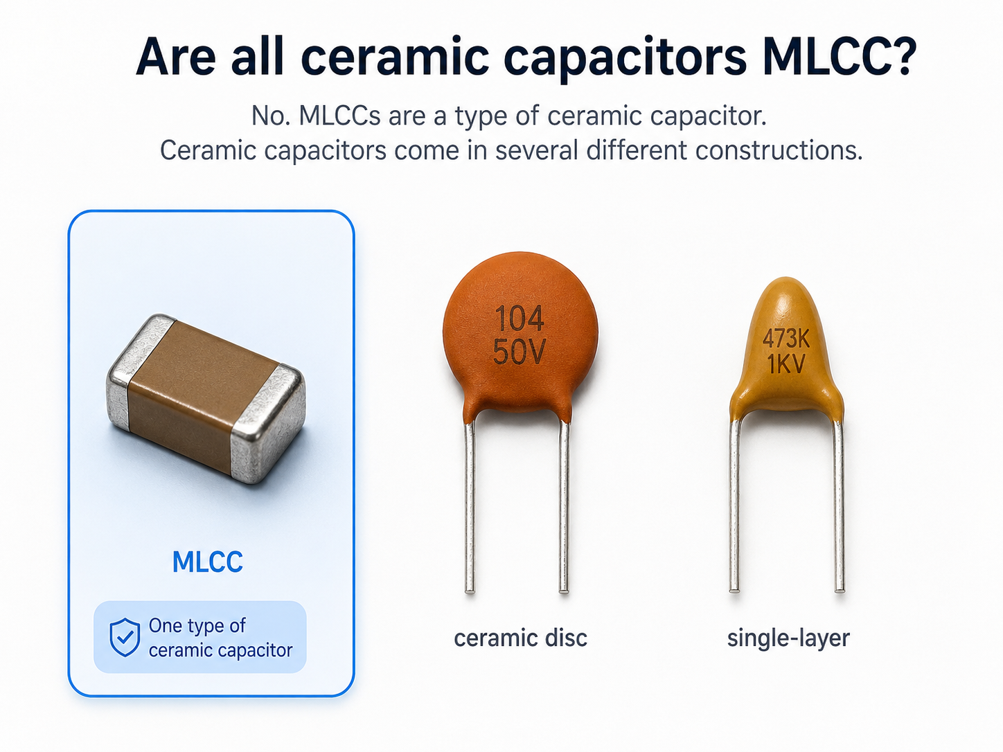
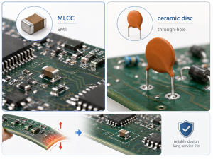
The capacitor may look different depending on its material and package. Some are small ceramic disc capacitors. Some are yellow or green polyester film capacitors. Some are box-type polypropylene capacitors. The appearance may change, but the value code follows the same basic reading method.

For example, a 104J capacitor marked on a small disc part and a 104J capacitor marked on a film capacitor may both have the same capacitance value of 0.1 µF. However, their voltage rating, temperature behavior, size, dielectric material, and application may not be the same.

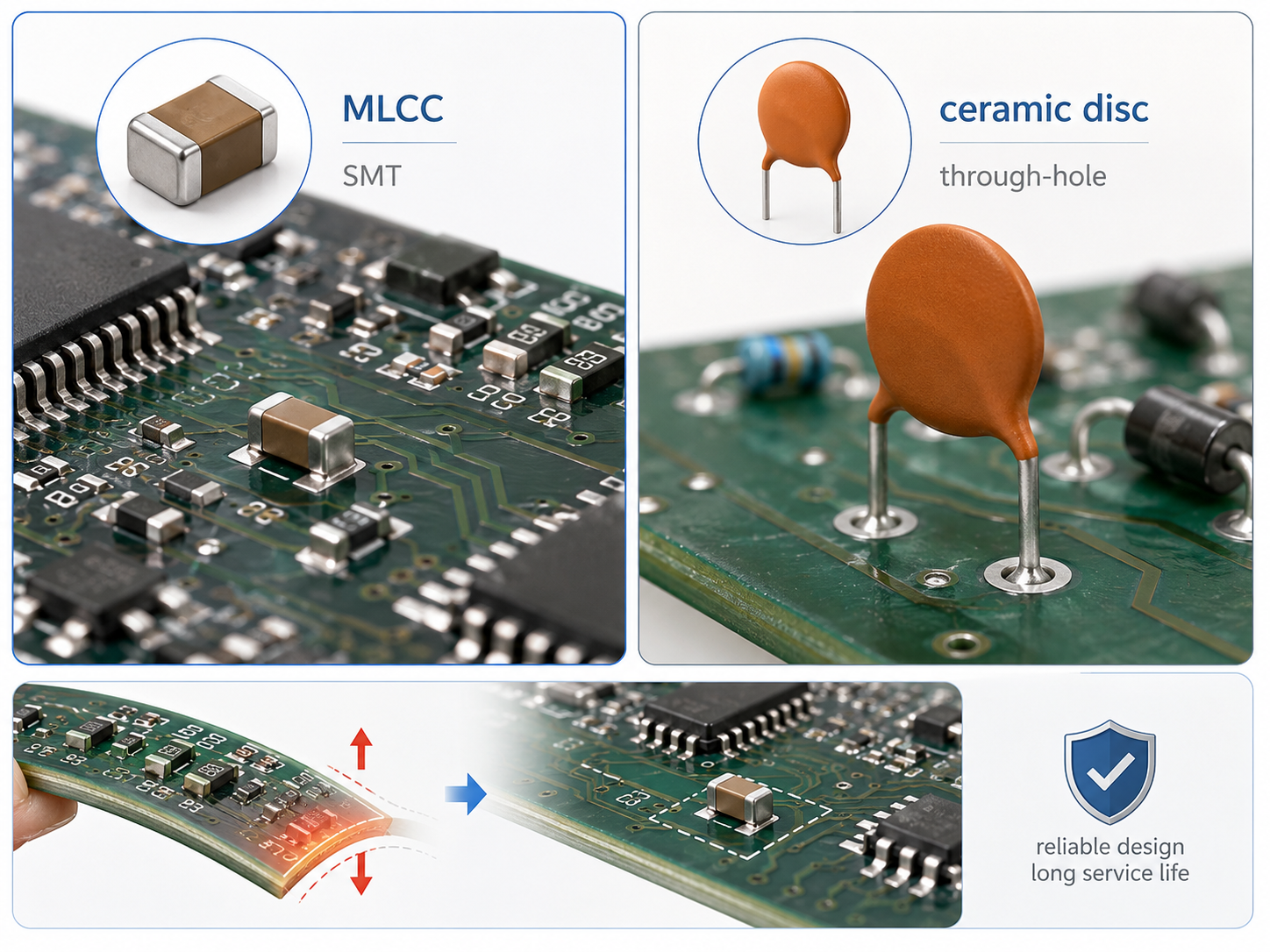
That is why reading only “104J” is not enough for final replacement. You should also check the voltage rating, material type, package size, lead spacing, temperature rating, and circuit function.

What Is the Value of a 104J Capacitor?

The value of a 104J capacitor is 100,000 pF, which equals 100 nF or 0.1 µF. This is the most important point for anyone searching for 104J capacitor value.

The code “104” uses the standard three-digit capacitor code system:

  • The first digit is 1.
  • The second digit is 0.
  • The third digit is 4.
  • The third digit means “add four zeros.”
  • So, 104 = 10 + four zeros = 100,000 pF.

So the capacitance is:

100,000 pF = 100 nF = 0.1 µF

This value is widely used because 0.1 µF capacitors are useful in many electronic circuits. They are especially common near IC power pins, where they help reduce noise and stabilize the local power supply.

A simple way to remember it is:

  • 101 = 100 pF
  • 102 = 1,000 pF
  • 103 = 10,000 pF
  • 104 = 100,000 pF
  • 105 = 1,000,000 pF

So when you see “104,” you can read it as 100 nF or 0.1 µF.

If the capacitor is marked as 104J, the capacitance value is still 0.1 µF. The letter “J” does not change the capacitance value. It only describes the tolerance.

What Does 104J Mean on a Capacitor?

The marking 104J has two parts: “104” and “J.” Each part gives a different piece of information.

The meaning is:

  • 104 = capacitance code
  • J = tolerance code

The “104” means the capacitor value is 100,000 pF. The “J” means the capacitance tolerance is ±5%.

Tolerance tells you how much the actual capacitance may vary from the marked value. For a 104J capacitor, the ideal value is 0.1 µF, but the real measured value may be slightly higher or lower.

For example:

  • Nominal value: 0.1 µF
  • Tolerance: ±5%
  • Acceptable range: about 0.095 µF to 0.105 µF

This means a 104J capacitor does not have to measure exactly 0.100 µF to be acceptable. If it is within the tolerance range, it is normally considered correct.

Common capacitor tolerance letters include:

LetterTolerance
J±5%
K±10%
M±20%

So, the difference between 104J and 104K is not the capacitance value. Both are usually 0.1 µF. The difference is tolerance. A 104J capacitor is more precise than a 104K capacitor.

This is important when choosing replacements. For general filtering, a 104K capacitor may sometimes work. For more sensitive timing, audio, or signal circuits, it is safer to keep the same tolerance or use a better one.

What Is the 104J Capacitor Value in pF, nF and µF?

The 104J capacitor value can be written in three common units: pF, nF, and µF. These units all describe the same capacitance, but they are used in different datasheets, drawings, and circuit diagrams.

The conversion is:

Unit104J Capacitor Value
pF100,000 pF
nF100 nF
µF0.1 µF

These three values are equal.

Many beginners become confused because one circuit diagram may show 0.1 µF, while another datasheet may show 100 nF, and the capacitor body may show 104J. In most cases, these are referring to the same capacitance value.

Here is a simple unit relationship:

  • 1 nF = 1,000 pF
  • 1 µF = 1,000 nF
  • 0.1 µF = 100 nF
  • 100 nF = 100,000 pF

So if you see “104J capacitor value in uF,” the answer is 0.1 µF. If you see “capacitor 104J 100n,” it means the same thing: 104J is a 100 nF capacitor.

For SEO and practical clarity, these expressions all point to the same value:

  • 104J capacitor value = 0.1 µF
  • capacitor 104J value = 100 nF
  • 104J capacitor value in uF = 0.1 µF
  • a 104J capacitor = 100,000 pF capacitor

This is why the 104J capacitor is often used as a quick reference example when learning capacitor codes.

How to Read a 104J Capacitor Code Correctly?

To read a 104J capacitor code correctly, separate the number code from the letter code. The number gives the capacitance value, and the letter gives the tolerance.

Use this method:

  • Read the first two digits as the base number.
  • Use the third digit as the number of zeros.
  • Treat the final result as pF.
  • Convert pF to nF or µF if needed.
  • Read the letter as the tolerance code.

For 104J:

  • First two digits: 10
  • Third digit: 4 zeros
  • Result: 100,000 pF
  • Converted value: 100 nF or 0.1 µF
  • Tolerance letter: J = ±5%

This method also works for many other capacitor markings.

Examples:

CodeValue in pFValue in nFValue in µF
101100 pF0.1 nF0.0001 µF
1021,000 pF1 nF0.001 µF
10310,000 pF10 nF0.01 µF
104100,000 pF100 nF0.1 µF
1051,000,000 pF1,000 nF1 µF

The same rule is often used on ceramic capacitors and film capacitors. However, larger capacitors may also print the capacitance directly, such as 0.1 µF, 100n, or 100nF.

One practical tip: if the capacitor has other markings, do not ignore them. Extra markings may show voltage, series, temperature grade, safety approval, or manufacturer code. For replacement, these details can matter as much as the capacitance value.

104J Capacitor

Is a 104J Capacitor Ceramic, Polyester or Polypropylene?

A 104J capacitor can be ceramic, polyester, polypropylene, or another dielectric type. The marking “104J” tells you capacitance and tolerance, but it does not always tell you the material.

This is a common misunderstanding. Some people think 104J always means ceramic. Others think it always means polyester film. In reality, 104J can appear on different capacitor families.

Common types include:

  • Ceramic 104J capacitor
    Often used for decoupling, bypassing, filtering, and general PCB circuits.
  • Polyester 104J capacitor
    Often used in audio, coupling, filtering, and general-purpose film capacitor applications.
  • Polypropylene 104J capacitor
    Often used where lower loss, better stability, or higher voltage performance is needed.
  • Safety-rated film capacitor
    Used in AC line filtering or interference suppression, but only when properly rated as X or Y safety capacitors.

The material affects important performance factors:

  • Temperature stability
  • Voltage rating
  • Size
  • ESR
  • Loss factor
  • Frequency behavior
  • Long-term reliability
  • Suitable application area

For example, a ceramic 104J capacitor may be excellent for compact PCB decoupling. A polypropylene 104J capacitor may be better for pulse circuits, snubber circuits, or applications that need lower dielectric loss. A polyester 104J capacitor may be suitable for general signal coupling or filtering.

So, when replacing a 104J capacitor, do not choose only by the 104J marking. Try to match the original capacitor type, voltage rating, package style, and working position in the circuit.

104J Capacitor Datasheet Overview

A 104J capacitor datasheet usually gives more than just the capacitance value. It helps engineers confirm whether the capacitor is suitable for the real circuit.

The most important datasheet items include:

ParameterTypical Meaning
Capacitance0.1 µF / 100 nF / 100,000 pF
ToleranceJ = ±5%
Rated Voltage50V, 100V, 250V, 400V, 630V or higher
DielectricCeramic, polyester, polypropylene, etc.
Temperature RangeDepends on series and material
PackageDisc, radial lead, box film, SMD, etc.
Lead SpacingImportant for through-hole replacement
Dissipation FactorLower is better for some AC or signal circuits
Insulation ResistanceImportant for leakage-sensitive circuits

The voltage rating is one of the most important specifications. A 104J 100V capacitor and a 104J 400V capacitor may have the same capacitance, but they are not the same component. The 400V part can handle a higher working voltage, while the 100V part may be smaller and cheaper.

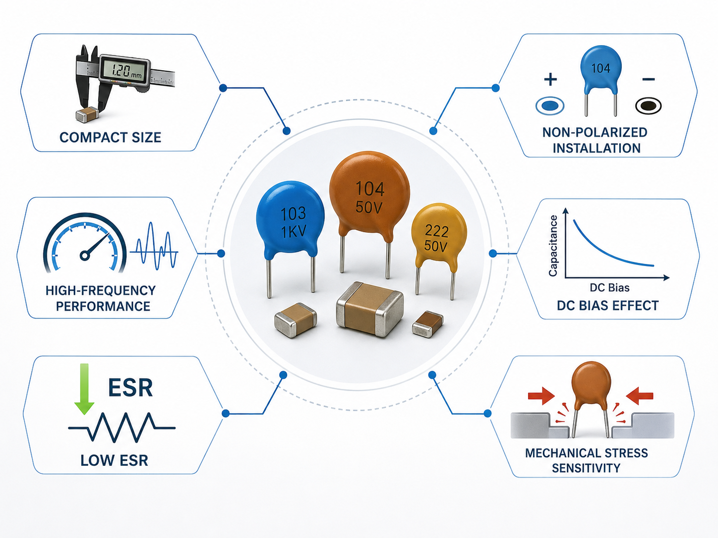
The dielectric material is also important. Ceramic capacitors can be small and economical, but their capacitance may change with voltage and temperature depending on the ceramic class. Film capacitors are often larger, but they can offer better stability in some applications.

A good 104J capacitor datasheet should help you answer these questions:

  • Is the capacitance 0.1 µF?
  • Is the tolerance ±5%?
  • What is the rated voltage?
  • What material is used?
  • What is the operating temperature range?
  • What is the package size?
  • Is it suitable for the circuit environment?

For repair work, try to match the original specifications as closely as possible. For new design work, select the capacitor according to the actual circuit function, voltage margin, temperature range, and reliability target.

What Is the Voltage Rating of a 104J Capacitor?

The voltage rating of a 104J capacitor tells you the maximum voltage the capacitor is designed to handle under specified conditions. It does not change the capacitance value.

This point is very important:

  • 104J 100V capacitor value = 0.1 µF
  • 104J 250V capacitor value = 0.1 µF
  • 104J 400V capacitor value = 0.1 µF
  • 104J 630V capacitor value = 0.1 µF

The capacitance stays the same. The voltage rating changes.

Common 104J capacitor voltage ratings include:

  • 50V
  • 100V
  • 250V
  • 400V
  • 630V
  • 1kV

A low-voltage 104J capacitor may be used in signal circuits, low-voltage power rails, microcontroller boards, and small electronic products. A high-voltage 104J capacitor may be used in power supplies, motor circuits, lighting drivers, snubber circuits, and high-voltage filtering applications.

When choosing voltage rating, do not select a capacitor with a voltage rating lower than the circuit voltage. In many designs, engineers use voltage margin. For example, a 12V circuit may use a 25V or 50V capacitor. A 100V circuit may require a 250V or higher rated capacitor, depending on spikes, ripple, and safety margin.

A higher voltage rating usually means:

  • Larger physical size
  • Higher cost
  • Better voltage margin
  • Different dielectric or package options

It is usually acceptable to replace a capacitor with the same capacitance and a higher voltage rating, as long as the package size, lead spacing, material type, and circuit requirements are suitable. However, replacing a high-voltage capacitor with a lower-voltage part is risky and should be avoided.

What Is the Difference Between 104J 100V, 250V, 400V and 630V Capacitors?

The main difference between 104J 100V, 250V, 400V, and 630V capacitors is voltage rating. Their capacitance value is the same: 0.1 µF. Their ability to handle voltage is different.

Here is a simple comparison:

MarkingCapacitanceToleranceVoltage Rating
104J 100V0.1 µF±5%100V
104J 250V0.1 µF±5%250V
104J 400V0.1 µF±5%400V
104J 630V0.1 µF±5%630V

A 104J 100V capacitor is often used in low-voltage or moderate-voltage electronic circuits. A 104J 250V capacitor may be used in higher voltage signal or filtering circuits. A 104J 400V capacitor may appear in power supplies, lighting circuits, or industrial boards. A 104J 630V capacitor is often used when more voltage margin is needed.

The voltage choice depends on:

  • Working voltage
  • Peak voltage
  • Ripple voltage
  • Surge voltage
  • Circuit location
  • Safety requirement
  • Temperature
  • Reliability target

For example, if the original part is a 104J 400V capacitor, using a 104J 100V capacitor as a replacement is usually not safe. The capacitance may match, but the voltage rating does not.

On the other hand, replacing a 104J 250V capacitor with a 104J 400V capacitor may be acceptable in many cases if the size and material are suitable. Still, you should check the circuit function before making the change.

A practical rule is simple: match the capacitance, match the tolerance when possible, and never go lower on voltage rating unless the circuit has been reviewed by a qualified engineer.

104J Capacitor

Where Is a 104J Capacitor Commonly Used?

A 104J capacitor is commonly used in circuits that need 0.1 µF capacitance for noise reduction, filtering, bypassing, coupling, or timing. Because 0.1 µF is a very useful value, 104J capacitors appear in many electronic products.

Common uses include:

  • Power supply decoupling
    A 104J capacitor is often placed near IC power pins to reduce high-frequency noise.
  • Bypass circuits
    It can provide a low-impedance path for unwanted AC noise.
  • Signal coupling
    In some circuits, it can pass AC signals while blocking DC voltage.
  • Filter circuits
    It can work with resistors or inductors to reduce noise or shape signals.
  • Audio circuits
    Polyester or film 104J capacitors may be used for coupling or tone control.
  • Motor and power circuits
    Higher-voltage film capacitors may be used for noise suppression or snubber functions.
  • LED drivers and lighting circuits
    104J capacitors may support filtering, EMI reduction, or control circuit stability.
  • Industrial control boards
    They can help stabilize control signals and reduce electrical noise.

In capacitor PCB design, 0.1 µF capacitors are often used as local decoupling capacitors. They are placed close to IC power pins to help reduce voltage disturbance. In this role, the physical placement of the capacitor can be as important as the capacitor value.

In repair work, you may find a 104J capacitor on power boards, control boards, amplifiers, adapters, LED lamps, small appliances, and automotive electronics. Before replacing it, check the voltage rating and material type carefully.

104J Capacitor

How to Choose the Right 104J Capacitor Replacement?

To choose the right 104J capacitor replacement, you need to match more than the printed code. The replacement should fit the circuit electrically, mechanically, and thermally.

Use this checklist:

  • Match the capacitance
    The replacement should be 0.1 µF, 100 nF, or 100,000 pF.
  • Match or improve the tolerance
    Replace 104J with ±5% when possible. A tighter tolerance may be acceptable, but a looser tolerance may not be suitable for sensitive circuits.
  • Match or exceed the voltage rating
    Do not replace a 400V part with a 100V part. Higher voltage may be acceptable if size and material fit.
  • Match the dielectric type
    Replace ceramic with ceramic when the circuit needs that behavior. Replace film with film when stability, AC performance, or pulse handling matters.
  • Check the package style
    Confirm through-hole, SMD, disc, box film, radial lead, or axial package.
  • Check lead spacing and body size
    The part must physically fit the PCB.
  • Check the circuit function
    Decoupling, coupling, filtering, timing, snubber, and safety circuits may require different capacitor types.
  • Check safety rating if used across AC lines
    Do not replace a safety capacitor with a normal capacitor. Use proper X or Y safety-rated parts.

A 104J capacitor replacement may look correct by value, but still fail in the circuit if the voltage rating, material, or safety classification is wrong.

For example, a 104J 630V polypropylene film capacitor may be used in a power or pulse circuit. Replacing it with a small ceramic capacitor marked 104J may not provide the same performance. The capacitance value may match, but the electrical behavior may be different.

When in doubt, use the original datasheet, circuit diagram, or manufacturer specification as the main reference.

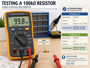
How to Test a 104J Capacitor With a Multimeter?

You can test a 104J capacitor with a digital multimeter if the meter has a capacitance measurement function. A basic resistance test can also help detect short circuits, but it cannot accurately measure capacitance.

Follow these steps:

  • Turn off power completely
    Never test a capacitor in a live circuit.
  • Discharge the capacitor safely
    Use a suitable resistor to discharge it before handling.
  • Remove one leg if needed
    In-circuit readings may be affected by other components.
  • Set the multimeter to capacitance mode
    Choose the capacitor measurement function.
  • Connect the probes to the capacitor leads
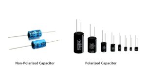
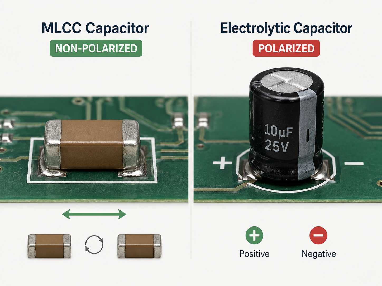
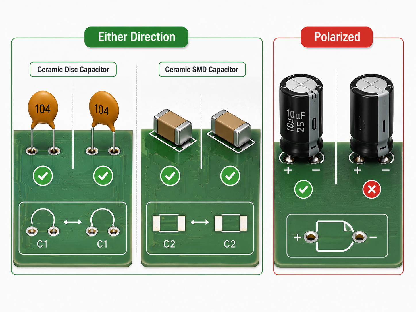
    Observe polarity only if the capacitor type is polarized. Most 104J ceramic or film capacitors are non-polarized.
  • Read the measured value
    A 104J capacitor should measure near 0.1 µF.
  • Compare with tolerance
    For 104J, a normal reading is usually around 0.095 µF to 0.105 µF, depending on meter accuracy and test conditions.
104J Capacitor

If the capacitor reads open, shorted, unstable, or far outside the expected value, it may be damaged. However, testing small capacitors can be affected by meter quality, lead contact, circuit connection, and dielectric behavior.

For more accurate testing, an LCR meter is better than a basic multimeter. An LCR meter can measure capacitance under more controlled test conditions and may also show ESR or loss factor.

For high-voltage capacitors, safety is critical. Some capacitors can hold charge after the circuit is turned off. Always discharge them properly before testing.

FAQs About 104J Capacitor

What Is a 104J Capacitor?

A 104J capacitor is usually a 0.1 µF capacitor with ±5% tolerance. The “104” means 100,000 pF, and the “J” means ±5%.

What Is the Value of a 104J Capacitor?

The value of a 104J capacitor is 100,000 pF, 100 nF, or 0.1 µF.

What Does 104J Mean on a Capacitor?

“104” is the capacitance code. It means 10 followed by four zeros in pF. “J” is the tolerance code, which means ±5%.

Is a 104J Capacitor the Same as 0.1 µF?

Yes. A 104J capacitor is normally the same capacitance value as 0.1 µF or 100 nF.

Is a 104J Capacitor Polarized?

Most 104J ceramic and film capacitors are non-polarized. However, always check the capacitor type and datasheet if you are not sure.

What Is the Difference Between 104J and 104K Capacitors?

Both are usually 0.1 µF capacitors. The difference is tolerance. 104J means ±5%, while 104K means ±10%.

Can I Replace a 104J Capacitor With a 104K Capacitor?

Sometimes, but not always. For general filtering, it may work. For precise timing, audio, or sensitive signal circuits, it is better to keep the same tolerance or use a tighter one.

Can I Use a Higher Voltage 104J Capacitor?

Yes, in many cases you can use a higher voltage 104J capacitor if the capacitance, package, material, and lead spacing are suitable. Do not use a lower voltage replacement unless the circuit has been reviewed.

What Is a 104J 100V Capacitor?

A 104J 100V capacitor is a 0.1 µF capacitor with ±5% tolerance and a 100V voltage rating.

What Is a 104J 400V Capacitor?

A 104J 400V capacitor is a 0.1 µF capacitor with ±5% tolerance and a 400V voltage rating. The higher voltage rating does not change the capacitance value.

Is a 104J Capacitor Ceramic or Film?

It can be ceramic or film. The marking “104J” tells the value and tolerance, but the capacitor material should be confirmed by appearance, datasheet, or part number.

Why Do 104J Capacitors Come in Different Colors?

104J capacitors may appear in different colors, such as red, green, yellow, blue, brown, or orange, because manufacturers use different coating materials, product series, voltage ratings, dielectric types, or visual designs. In most cases, the color itself does not directly define the capacitance value. A red 104J capacitor, a green 104J capacitor, and a yellow 104J capacitor can all have the same 0.1 µF value if they are marked “104J.” To identify the capacitor correctly, always check the printed code, voltage rating, dielectric material, package size, and datasheet instead of relying only on color.

Where Is a 104J Capacitor Used?

It is commonly used in decoupling, bypassing, filtering, coupling, audio circuits, power supplies, LED drivers, industrial boards, and control circuits.

How Do I Test a 104J Capacitor?

Use a multimeter with capacitance mode or an LCR meter. A good 104J capacitor should measure close to 0.1 µF, usually within the allowed tolerance range.

To summarize, 104J capacitor is a 0.1 µF capacitor, also written as 100 nF or 100,000 pF, and the “J” marking usually means ±5% tolerance. Understanding this code helps you read capacitor markings, compare voltage ratings, identify material types, choose replacements, and test parts more confidently.

For most users, the key is simple: “104” gives the value, “J” gives the tolerance, and the voltage rating must be checked separately. A 104J 100V capacitor, 104J 250V capacitor, 104J 400V capacitor, and 104J 630V capacitor may all share the same capacitance value, but they are not interchangeable in every circuit.

When replacing a 104J capacitor, match the capacitance, tolerance, voltage rating, dielectric type, package size, and circuit function. That is the safest way to avoid choosing a part that looks correct but performs poorly in the real application.

You may also like

How to Identify, Test and Replace a Fusible Resistor?

June 12th, 2026

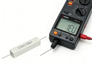
A fusible resistor is a protective resistor that provides normal resistance control while adding a controlled open-circuit function under overload. When current or heat exceeds its rated limit, it disconnects the circuit path instead of continuing to burn, drift, or damage nearby components.

To use a fusible resistor correctly, it is important to understand its working principle, material structure, resistance value, markings, color code, datasheet parameters, identification method, testing process, selection rules, and replacement steps. This guide explains each part in a clear order, so the correct fusible resistor can be identified, verified, selected, and replaced with fewer mistakes.

Fusible Resistor, https://www.bestpcbs.com/blog/2026/06/fusible-resistor/

What Is a Fusible Resistor?

A fusible resistor is a protective resistor that combines resistance control and fail-safe circuit protection in one component. Under normal operation, it works like a resistor by limiting current, dividing voltage, or supporting circuit stability. When abnormal current exceeds its rated limit, it opens the circuit safely like a fuse.

This component is widely used in power supplies, adapters, LED drivers, chargers, home appliances, audio equipment, and IoT circuit board assemblies. Its main function is not only to provide a resistance value, but also to reduce the risk of overheating, burning, or secondary circuit damage.

A fusible resistor may look similar to a normal resistor, but its internal structure and safety behavior are different. It is usually designed to fail in a controlled open-circuit mode instead of burning continuously or creating a short circuit.

Why Is a Fusible Resistor Important?

A fusible resistor is important because it helps protect circuits from overcurrent, short-circuit faults, surge stress, and abnormal load conditions. In compact electronic products, one failed component can affect the whole board, so controlled failure is critical.

In many power input sections, the fusible resistor is placed near the AC input, DC input, rectifier circuit, or switching power area. When a fault occurs, it can disconnect the current path before heat spreads to surrounding components.

It also helps reduce board-level risk in high-density assemblies. For IoT circuit board products, compact layouts, wireless modules, power ICs, sensors, and charging circuits often share limited space. A properly selected fusible resistor improves safety and product reliability without taking much board area.

How Does a Fusible Resistor Work?

A fusible resistor works in two stages: normal resistance mode and protection open-circuit mode.

  1. During normal operation, current flows through the resistor element.
  2. The resistor provides its rated resistance value, such as 1 Ω, 10 Ω, 47 Ω, or 100 Ω.
  3. If current rises above the safe limit, the resistor heats rapidly.
  4. The fusible element reaches its failure point.
  5. The resistor opens the circuit and stops current flow.
  6. The circuit is protected from further overheating or component damage.

The key point is that a fusible resistor is designed to fail safely. A normal resistor may overheat, discolor, crack, or continue burning under severe fault conditions. A fusible resistor is made to open the circuit under defined overload conditions.

What Are Fusible Resistors Made Of?

Fusible resistors are usually made from metal oxide film, wire wound elements, ceramic cores, flame-retardant coatings, and conductive end caps. The exact construction depends on power rating, package type, and application.

A metal oxide fusible resistor is common in power circuits because it has stable resistance, good heat tolerance, and reliable overload behavior. It is often used in adapters, power boards, and control circuits.

A fusible wire wound resistor uses resistance wire wound around a ceramic or insulating core. This type is suitable for higher power applications and surge-prone circuits. It is often found in power supplies, industrial boards, and equipment with stronger current loads.

An SMD fusible resistor uses a compact surface-mount structure. It is suitable for space-limited PCB assemblies, including IoT circuit board modules, compact chargers, sensor products, and communication boards.

What Is the Value of a Fusible Resistor?

The value of a fusible resistor refers to its resistance rating, usually measured in ohms (Ω). Common values include 1 ohm fusible resistor, 10 ohm fusible resistor, 47 ohm fusible resistor, and 100 ohm fusible resistor.

The correct value depends on the circuit position and protection target. A low-value fusible resistor may be used for current sensing, inrush limitation, or input protection. A higher-value fusible resistor may be used in signal paths, startup circuits, or voltage-dropping sections.

When selecting a fusible resistor value, the following parameters should match the original circuit requirement:

  • Resistance value
  • Power rating
  • Tolerance
  • Voltage rating
  • Fusing behavior
  • Package size
  • Temperature rating
  • Flame-retardant grade

Replacing only by resistance value is not enough. For example, a 10 ohm normal resistor and a 10 ohm fusible resistor may show the same resistance on a multimeter, but their overload behavior is different.

What Are the Markings on a Fusible Resistor?

Fusible resistor markings help identify resistance value, tolerance, package type, and sometimes safety characteristics. Through-hole fusible resistors often use color bands, while SMD fusible resistors commonly use printed numeric codes.

Common marking types include:

  • Color bands for axial through-hole fusible resistors
  • Three-digit SMD code for standard surface-mount values
  • Four-digit SMD code for higher precision values
  • Letter suffixes for tolerance or series information
  • Body color or coating type for flame-retardant identification
  • Datasheet part number for exact electrical behavior

Some fusible resistors may not have a clear “fusible” label on the body. Therefore, visual appearance alone is not reliable. The safest method is to confirm the part number, board position, circuit function, and datasheet details.

Fusible Resistor Markings, https://www.bestpcbs.com/blog/2026/06/fusible-resistor/

What Is the Color Code for a Fusible Resistor?

The fusible resistor color code usually follows standard resistor color code rules. The first bands show resistance value, the multiplier band shows the number of zeros, and the tolerance band shows allowable variation.

Common examples include:

Color CodeValueTolerance
Brown Black Gold Gold1 Ω±5%
Brown Black Black Gold10 Ω±5%
Yellow Violet Black Gold47 Ω±5%
Brown Black Brown Gold100 Ω±5%

However, color code alone does not confirm fusible function. A normal resistor and a fusible resistor may share the same color bands. The circuit location, datasheet, flame-retardant coating, and original BOM information should be checked before replacement.

How to Calculate Fusible Resistor Color Codes?

Fusible resistor color code calculation can be done with the same method used for standard resistors. The key is to calculate resistance first, then confirm whether the component is truly fusible.

Step-by-step method:

  • Identify the first color band.
  • Identify the second color band.
  • Check the multiplier band.
  • Multiply the first two digits by the multiplier.
  • Read the tolerance band.
  • Confirm the part type from datasheet or circuit position.

    Example:
    A resistor marked brown, black, black, gold means:

    • Brown = 1
    • Black = 0
    • Black multiplier = ×1
    • Gold tolerance = ±5%
    • Final value = 10 Ω ±5%

    For SMD fusible resistor parts, use the printed marking instead of color bands. For example, 100 usually means 10 Ω, while 101 means 100 Ω. Always verify the marking rule from the component series because some manufacturers use special codes.

    What Are the Types of Fusible Resistors?

    Fusible resistors are classified by structure, package, and circuit use. The right type depends on power rating, surge stress, board space, and mounting method.

    • Metal Oxide Fusible Resistor
      Provides stable resistance, heat resistance, and flame-retardant performance. It is commonly used in adapters, LED drivers, power input circuits, and control boards.
    • Fusible Wire Wound Resistor
      Uses resistance wire wound around an insulating core. It supports higher power and stronger surge conditions, making it suitable for power supplies and industrial circuits.
    • Fusible Film Resistor
      Offers stable performance in a compact structure. It is used in consumer electronics, compact modules, and PCB assemblies requiring controlled open-circuit failure.
    • SMD Fusible Resistor
      Designed for surface-mount assembly and space-saving layouts. It is suitable for IoT circuit board assemblies, chargers, sensor modules, and communication boards.
    • Through-Hole Fusible Resistor
      Uses leaded terminals and is easier to inspect, test, and replace. It is often used in power boards, appliances, and repairable electronic products.
    • Low-Ohm Fusible Resistor
      Values such as 1 ohm fusible resistor and 10 ohm fusible resistor are used for input protection, current limiting, startup paths, and surge-related circuits.
    • Medium-Value Fusible Resistor
      Values such as 47 ohm fusible resistor and 100 ohm fusible resistor are used in control circuits, voltage-dropping paths, and protection networks.

    What Is a Fusible Resistor Used For?

    A fusible resistor is used in circuits where resistance control and fault protection are both required. It is commonly placed in positions where overcurrent may occur due to short circuits, surge voltage, component failure, or wrong input conditions.

    Common applications include:

    • Power supply input protection
    • AC/DC adapter circuits
    • LED driver protection
    • Battery charger circuits
    • Home appliance control boards
    • Audio amplifier circuits
    • IoT circuit board power sections
    • Industrial control modules
    • Sensor and communication boards

    In these applications, the fusible resistor helps protect the circuit before a fault spreads. It is especially valuable in boards where compact size, stable operation, and controlled failure behavior are required.

    What Is the Difference Between a Fusible Resistor and a Normal Resistor?

    A fusible resistor provides resistance and opens the circuit during abnormal overload. A normal resistor mainly controls current or voltage and does not provide the same controlled protection.

    The key difference is failure behavior. A fusible resistor is designed to fail as an open circuit under overload. A normal resistor may overheat, burn, drift, crack, or continue conducting under fault conditions.

    ItemFusible ResistorNormal Resistor
    Main FunctionResistance + circuit protectionResistance only
    Failure ModeOpens circuit under overloadMay overheat, burn, or drift
    Protection RoleUsed in safety-related positionsUsed in general circuit paths
    Common LocationPower input, startup circuit, surge path, protection circuitSignal path, divider circuit, bias circuit, general load
    Replacement RuleMatch resistance, power, package, and fusible behaviorMatch resistance, tolerance, and power
    Overcurrent ResponseDisconnects under abnormal currentNo guaranteed protection response
    Flame-Retardant ConstructionCommon in fusible seriesDepends on resistor type
    Selection RiskWrong type weakens protectionWrong value affects circuit function

    A normal resistor should not replace a fusible resistor in protection positions. Even if the resistance value is the same, the overload behavior may be completely different.

    What Are the Advantages of Fusible Resistors?

    Fusible resistors offer practical benefits in board-level protection and production reliability.

    • Two functions in one component: Provides resistance and fault protection.
    • Controlled failure behavior: Opens the circuit under abnormal current.
    • Space saving: Reduces extra protection components in compact boards.
    • Wide value range: Available in 1 Ω, 10 Ω, 47 Ω, 100 Ω, and many other values.
    • Multiple packages: Available in SMD and through-hole formats.
    • Improved safety: Helps reduce overheating and secondary damage.
    • Useful for compact products: Suitable for IoT circuit board and small electronic assemblies.

    These advantages make fusible resistors suitable for protection circuits where board space, safety, and stable operation must be balanced.

    What Are the Limitations of Fusible Resistors?

    Fusible resistors also have limits. They should be selected according to real circuit conditions instead of being treated as universal protection parts.

    • One-time protection: Once blown, the part must be replaced.
    • Limited current range: Not suitable for every high-current fault condition.
    • Selection sensitivity: Wrong power rating may cause false failure or weak protection.
    • Heat influence: Poor thermal layout can affect reliability.
    • Not a full fuse replacement: It cannot replace every fuse application.
    • Datasheet matching required: Fusing time and overload behavior vary by series.

    A fusible resistor should be treated as a safety-related component. The resistance value, power rating, overload curve, mounting method, and circuit position should all be checked before final selection.

    Fusible Resistor Datasheet Overview

    A fusible resistor datasheet should be checked before selection, replacement, or production approval. It confirms the electrical value, package, safety behavior, and overload performance.

    Datasheet ItemWhat to Check
    Resistance Value1 Ω, 10 Ω, 47 Ω, 100 Ω, or required custom value
    Tolerance±1%, ±2%, ±5%, ±10%
    Rated Power1/8W, 1/4W, 1/2W, 1W, 2W or higher
    Maximum Working VoltageRated voltage limit
    Fusing CharacteristicFusing current, overload level, and fusing time
    Overload RatingShort-time overload capacity
    Temperature RangeOperating and storage temperature
    Temperature CoefficientResistance change under temperature variation
    Package SizeSMD size, body size, or lead spacing
    Mounting TypeSMD or through-hole
    Coating MaterialFlame-retardant coating, ceramic body, or insulated coating
    Soldering ConditionReflow, wave soldering, or hand soldering limits
    Safety ApprovalUL, RoHS, or other applicable compliance
    Failure ModeOpen-circuit behavior under overload
    Manufacturer SeriesExact product family and datasheet series

    The most important items are resistance value, rated power, fusing characteristic, package size, and failure mode. Two fusible resistors with the same ohm value may behave differently during overload, so datasheet comparison is required before using an alternative part.

    How to Identify a Fusible Resistor?

    A fusible resistor should be identified through circuit position, markings, appearance, and datasheet confirmation. Visual inspection alone is not enough because many fusible resistors look similar to normal resistors.

    1. Check the PCB Reference Designator
    Look near the component label on the board. Fusible resistors may be marked as FR, RF, F-R, R-F, fusible resistor, or similar codes. However, markings vary by manufacturer, so the reference designator should be used as a clue, not final proof.

    2. Check the Circuit Location
    Fusible resistors are often placed near power input areas, rectifier circuits, switching power supplies, startup circuits, LED driver inputs, or charger protection sections. If the resistor is close to the input power path, it may have a protection role.

    3. Read the Body Marking
    Through-hole types may use color bands. SMD fusible resistors may use 3-digit or 4-digit codes. Record the marking clearly before removal because burned components may become harder to read later.

    4. Inspect the Component Body
    Many fusible resistors use flame-retardant coating, ceramic bodies, or special insulating layers. Some may appear gray, blue, green, or white depending on series. Body color can help, but it cannot confirm the part alone.

    5. Compare with BOM or Schematic
    The BOM or schematic is the most reliable identification source. Check whether the part description includes fusible resistor, flameproof resistor, safety resistor, metal oxide fusible resistor, or fusible wire wound resistor.

    6. Search the Part Number
    If a manufacturer code or series number is visible, compare it with the datasheet. Confirm resistance, tolerance, power rating, package, and fusing behavior.

    7. Check Failure Condition
    A failed fusible resistor may show cracks, discoloration, burn marks, or open-circuit behavior. Some fail internally with no visible damage, so electrical testing is still required.

    8. Confirm Before Replacement
    Do not replace the part only by size or resistance. Confirm that the replacement has the same fusible function and suitable safety behavior.

      How to Test a Fusible Resistor?

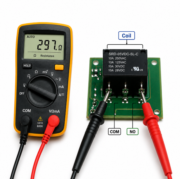
      A fusible resistor is usually tested with a digital multimeter. The purpose is to confirm whether it is normal, open, drifted, or damaged. Before testing, power must be fully removed from the circuit.

      1. Disconnect Power Completely
      Remove all power sources before testing. For power supply boards, chargers, and high-voltage circuits, wait until the circuit is safe to handle.

      2. Discharge Capacitors
      Large capacitors may hold charge after power is removed. Discharge them safely before touching the board or measuring resistance.

      3. Inspect the Resistor Visually
      Check for cracks, burn marks, coating damage, lifted pads, darkened PCB areas, or damaged nearby components. Visible damage often indicates overload or a downstream short.

      4. Set the Multimeter to Resistance Mode
      Select the appropriate ohm range. For low-value parts such as 1 ohm fusible resistor, use a low-resistance range if available.

      5. Measure Across Both Terminals
      Place probes on both ends of the resistor. A normal part should read close to its rated resistance within tolerance.

      6. Compare with the Rated Value
      Compare the measured value with the marking or datasheet. For example, a 10 ohm fusible resistor with ±5% tolerance should be close to 10 Ω.

      7. Check for Open Circuit
      If the meter shows OL, infinite resistance, or no continuity, the fusible resistor is likely blown.

      8. Check for Resistance Drift
      If the value is much higher than rated, the resistor may be heat-damaged or aged. Drifted parts should be replaced because protection and circuit performance may be unreliable.

      9. Lift One Side if the Reading Is Unclear
      In-circuit measurement may be affected by parallel components. If the reading does not make sense, desolder one side and test again.

      10. Check Downstream Components
      If the fusible resistor is blown, test rectifier diodes, MOSFETs, capacitors, ICs, load circuits, and power rails. A blown fusible resistor is often caused by another failed component.

      11. Test After Replacement
      After installing a new fusible resistor, check resistance again. Then power the circuit carefully, preferably with current limitation, and monitor temperature and voltage.

        Fusible Resistor Test, https://www.bestpcbs.com/blog/2026/06/fusible-resistor/

        How to Choose the Right Fusible Resistor?

        Choosing the right fusible resistor requires matching electrical value, protection behavior, package, and operating environment. Resistance value alone is not enough.

        • Match the Resistance Value
          Use the same resistance value as the original part, such as 1 Ω, 10 Ω, 47 Ω, or 100 Ω. A different value may change current flow, voltage drop, startup behavior, or protection response.
        • Match the Power Rating
          The rated power must support normal operation without overheating. A lower power rating may fail too early. A much higher rating may delay protection and reduce safety performance.
        • Confirm the Fusible Characteristic
          The replacement must be a true fusible resistor. It should open safely under overload instead of burning or shorting.
        • Check the Fusing Time
          Different series open at different overload levels and time ranges. Choose a part with fusing behavior close to the original datasheet.
        • Match the Package Type
          Use the correct package, such as SMD or through-hole. For SMD parts, match pad size and package code. For through-hole parts, match lead spacing and body size.
        • Check the Working Voltage
          The resistor must support the circuit voltage under normal use. Insufficient voltage rating can cause breakdown or unsafe operation.
        • Check the Temperature Rating
          Select a resistor that can operate under the product’s thermal conditions. High-temperature environments require stronger thermal stability.
        • Review Tolerance Requirements
          Tolerance affects circuit accuracy. For protection positions, ±5% or ±10% may be common, but the original circuit requirement should be followed.
        • Confirm Flame-Retardant Construction
          For input power and safety-related positions, flame-retardant coating or certified safety construction is important.
        • Check Assembly Compatibility
          Confirm reflow, wave soldering, or hand soldering conditions. Wrong soldering temperature can damage the resistor before the product is used.
        • Avoid Unknown Substitutes
          Unknown parts may have unstable fusing behavior. Use verified parts with clear datasheets and consistent supply.
        • Confirm Application Fit
          Power supplies, LED drivers, chargers, industrial boards, and IoT circuit board assemblies may require different resistor structures. Select the type based on actual circuit stress, not only part appearance.

        How to Replace Fusible Resistors?

        A fusible resistor should be replaced only after checking the cause of failure. If the original fault remains, the new resistor may blow immediately.

        1. Turn Off and Isolate Power
        Disconnect the board from all power sources. For high-voltage circuits, confirm that no dangerous voltage remains.

        2. Discharge Stored Energy
        Discharge capacitors safely before touching the circuit. This is especially important for power supply boards and charger circuits.

        3. Record the Original Part Information
        Take a photo of the resistor position, marking, body color, and nearby components. Record resistance value, package type, and board reference code.

        4. Confirm the Original Specification
        Check the BOM, schematic, or datasheet. Confirm resistance, power rating, tolerance, package, voltage rating, and fusible behavior.

        5. Inspect the Surrounding Circuit
        Look for damaged diodes, capacitors, MOSFETs, ICs, dark PCB areas, cracked solder joints, or shorted loads.

        6. Test for Short Circuits
        Before removing the resistor, check downstream resistance to ground or across power rails. A shorted circuit must be repaired before installing a new part.

        7. Remove the Failed Resistor
        Use proper soldering or desoldering tools. Avoid pulling the part by force because this may lift pads or damage traces.

        8. Clean the Pads
        Remove old solder and residue. Inspect the pads and copper traces for heat damage or lifting.

        9. Install the Correct Replacement
        Use a replacement with the same fusible function and matching electrical specifications. Do not use a normal resistor in a protection position.

        10. Control Soldering Heat
        Apply suitable soldering temperature and time. Excessive heat may damage the resistor or weaken the pads.

        11. Inspect the Solder Joints
        Check for solder bridges, cold joints, poor wetting, or misalignment. For SMD parts, confirm both terminals are properly soldered.

        12. Measure the Installed Resistor
        Check resistance after installation. The reading should match the expected value unless parallel circuit paths affect the measurement.

        13. Power Up Carefully
        Use current-limited power when possible. Monitor input current, output voltage, and resistor temperature.

        14. Confirm Stable Operation
        If the new fusible resistor heats abnormally or fails again, stop testing and inspect the fault circuit again.

        15. Document the Replacement
        Record the replacement part number and test result. This helps maintain consistency during repair, production, or future sourcing.

          Fusible Resistor Replacement, https://www.bestpcbs.com/blog/2026/06/fusible-resistor/

          FAQs About Fusible Resistors

          Q1: Is a power resistor the same as a fusible resistor?
          A1: No. A power resistor is made to handle higher power dissipation, while a fusible resistor is made to open the circuit under abnormal overload. Some fusible resistors can also be power-rated, but the two terms are not the same.

          Q2: Can I replace a fusible resistor with a normal resistor?
          A2: No, not in safety-related positions. A normal resistor may match the same ohm value, but it does not provide the same controlled open-circuit protection. The replacement should match resistance, power rating, package, and fusible behavior.

          Q3: What is the difference between fusible resistor and fuse?
          A3: A fuse is mainly used to break the circuit during overcurrent. A fusible resistor provides resistance during normal operation and also opens during overload. It combines current control and fault protection in one component.

          Q4: How do I know if a fusible resistor is blown?
          A4: Use a multimeter in resistance mode. If the reading shows OL, infinite resistance, or a value far above the rated range, the fusible resistor is likely blown or damaged.

          Q5: Can a fusible resistor fail without visible burn marks?
          A5: Yes. Some fusible resistors open internally without obvious body damage. Visual inspection is useful, but resistance testing is more reliable.

          Q6: Are fusible resistor color codes the same as normal resistor color codes?
          A6: Usually yes for resistance value. However, color bands only show resistance and tolerance. They do not always confirm fusible behavior. Datasheet confirmation is recommended.

          Q7: What does a 1 ohm fusible resistor do?
          A7: A 1 Ω fusible resistor may be used for input protection, inrush limitation, or current-related protection paths. Its exact role depends on the circuit position and power rating.

          Q8: What should be checked before replacing a blown fusible resistor?
          A8: Check for shorted diodes, MOSFETs, capacitors, ICs, damaged traces, and wrong input voltage. A blown fusible resistor often indicates another fault in the circuit.

          Conclusion

          A fusible resistor is a small but important safety component in electronic products. It provides resistance during normal operation and opens the circuit during abnormal overload. Correct identification, testing, and replacement help improve board reliability, reduce repeat failures, and protect surrounding components.

          EBest Circuit provides component sourcing and PCB assembly service with fusible resistors. For stable quality, matching specifications, and reliable order support, contact sales@bestpcbs.com to get a professional quotation and start your fusible resistor order with EBest.

          You may also like

          10k Resistor Color Code: What Is the Correct Answer?

          June 12th, 2026

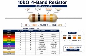
          The standard 10k resistor color code is brown-black-orange for a 3-band value reading. A common 4-band 10k resistor is brown-black-orange-gold, meaning 10,000 ohms with ±5% tolerance.

          4-band 10k resistor

          A common 5-band 10k resistor is brown-black-black-red-brown, meaning 10,000 ohms with ±1% tolerance.

          5-Band 10k Resistor Color Code

          A 10k resistor equals 10,000 ohms, or 10 kΩ. It is one of the most widely used resistor values in PCB circuits for pull-up, pull-down, voltage dividers, sensor inputs, timing networks, biasing circuits, and signal conditioning.

          What Is a 10k Resistor?

          A 10k resistor is a passive electronic component with a resistance value of 10,000 ohms. The letter k means kilo, so 10kΩ = 10 × 1,000Ω = 10,000Ω. In a circuit, a 10k resistor limits current, divides voltage, sets logic levels, or stabilizes input signals.

          Why Is the 10k Resistor Color Code Important?

          The 10k resistor color code is crucial to identify the resistor value before soldering, testing, repair, or replacement. Wrong resistor values can cause incorrect voltage levels, unstable sensor readings, MCU boot failure, weak pull-up signals, timing errors, or excessive current.

          How Does a Resistor Color Code Work?

          A resistor color code works by using colored bands to represent digits, multipliers, tolerance, and sometimes temperature coefficient.

          ColorDigitMultiplierCommon Tolerance
          Black0×1
          Brown1×10±1%
          Red2×100±2%
          Orange3×1,000
          Yellow4×10,000
          Green5×100,000±0.5%
          Blue6×1,000,000±0.25%
          Violet7×10,000,000±0.1%
          Gray8×100,000,000±0.05%
          White9×1,000,000,000
          Gold×0.1±5%
          Silver×0.01±10%

          What Is the 4-Band 10k Resistor Color Code?

          The 4-band 10k resistor color code is brown, black, orange, gold for a ±5% resistor. Calculation: 10 × 1,000 = 10,000Ω = 10kΩ.

          4-Band 10k Resistor Color Code

          What Is the 5-Band 10k Resistor Color Code?

          The 5-band 10k resistor color code is brown, black, black, red, brown for ±1% precision. Calculation: 100 × 100 = 10,000Ω = 10kΩ.

          10k Resistor Color Bands Compared: 4-Band vs 5-Band

          TypeColor BandsValueToleranceBest Use
          4-bandBrown-black-orange-gold10kΩ±5%General pull-up, pull-down, LED signal circuits
          5-bandBrown-black-black-red-brown10kΩ±1%Precision sensor, reference voltage, industrial control
          6-bandValue bands + tolerance + TCR band10kΩDependsTemperature-sensitive circuits

          How to Read a 10k Resistor Color Code Correctly?

          Place the tolerance band on the right, read left to right. For brown-black-orange-gold, brown=1, black=0, orange=×1,000, gold=±5%, resulting in 10kΩ ±5%.

          What Is the 10k Surface Mount Resistor Code?

          Common SMD markings: 103 (10+3 zeros = 10kΩ) or 1002 (100+2 zeros = 10kΩ).

          Materials, Features, and Advantages

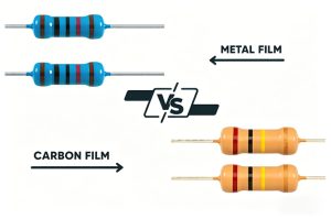
          10k resistors may be carbon film, metal film, thick film SMD, thin film SMD, or wirewound. Features: 10kΩ value, ±5% or ±1% tolerance, through-hole or SMD packages, moderate power rating, widely applicable.

          Applications in PCB Design

          Used for pull-up/pull-down circuits, voltage dividers, sensor interfaces, timing, transistor bias, communication line biasing, and general PCB logic stabilization.

          Procurement and Manufacturing Tips

          Check BOM, package, tolerance, power rating, and source reliability. Use AOI and electrical testing in mass production. Confirm resistor value to avoid wrong placements or rework.

          Testing and Quality Standards

          Verify with multimeter, LCR meter, flying probe, or functional testing. Factory quality standards include component inspection, IPC workmanship, solder joint inspection, and traceability.

          Common Failures and How to Avoid Them

          Failures include wrong value, cracked body, poor solder, overheating, color misreading. Avoid by BOM confirmation, correct reel loading, process verification, and first-article inspection.

          FAQs About 10k Resistor Color Code

          What is the 10k ohm resistor color code? Brown-black-orange for 3-band; brown-black-orange-gold for 4-band ±5%.

          What is the 4 band 10k resistor color code? Brown, black, orange, gold; 10 × 1,000 = 10kΩ ±5%.

          What is the 5 band 10k resistor color code? Brown, black, black, red, brown; 100 × 100 = 10kΩ ±1%.

          What does brown black orange gold resistor mean? 10kΩ ±5%, standard 4-band through-hole resistor.

          What are the 10k resistor colors? Brown, black, orange for value; gold for ±5% tolerance; 5-band: brown-black-black-red-brown.

          How do you read a 10k resistor color code? Place tolerance band right, read left-to-right, convert colors to digits, apply multiplier.

          What is the 10k surface mount resistor code? 103 or 1002 markings; 10kΩ SMD resistor.

          Is a 103 resistor the same as a 10k resistor? Yes, 103 = 10kΩ.

          What is a 10k linear potentiometer pinout? Three pins: two ends of resistive track, middle wiper; wiper output changes as shaft rotates.

          Can I replace a 10k resistor with another value? Only after circuit verification; different values may alter voltage, bias, timing.

          Conclusion

          The 10k resistor color code varies with 4-band or 5-band type: 4-band is brown-black-orange-gold, 5-band is brown-black-black-red-brown. SMD markings include 103 or 1002. For precision applications, choose appropriate tolerance and material type.

          If you need keywords-related products or services, EBest PCB can support PCB manufacturing, PCB assembly, OEM production, ODM development, sample builds, batch production, and custom engineering solutions.

          If you’re sourcing reliable PCB/PCBA manufacturing — OEM, ODM, prototyping, mass production, or custom engineering solutions — reach out to our engineering team for technical support and a quote at sales@bestpcbs.com.

          You may also like

          What Is the Value of a 106 Capacitor? How to Test It?

          June 11th, 2026

          A 106 capacitor has a capacitance value of 10 uF, which equals 10,000 nF or 10,000,000 pF. The number “106” follows the standard three-digit capacitor code rule: the first two digits are the base number, and the third digit shows how many zeros are added in picofarads.

          This guide explains the 106 capacitor value, capacitor code 106, voltage rating, tolerance, polarity, package size, datasheet parameters, testing method and replacement rules. It also adds practical PCB assembly advice, so the capacitor can be selected, mounted and tested correctly in real electronic products.

          106 Capacitor, https://www.bestpcbs.com/blog/2026/06/106-capacitor/

          What Does 106 Mean on a Capacitor?

          A 106 capacitor means the capacitor has a value of 10 uF. In the standard capacitor marking system, “10” is the significant number, and “6” means six zeros are added after it in picofarads.

          The calculation is 10 × 10⁶ pF = 10,000,000 pF. After unit conversion, this becomes 10,000 nF or 10 uF. This is why a capacitor marked 106 is not 106 pF, but a much larger 10 uF capacitor.

          The 106 marking appears on ceramic capacitors, tantalum capacitors, electrolytic capacitors and SMD capacitors. However, this marking only identifies capacitance. Voltage rating, tolerance, polarity, dielectric material and package size must be checked separately before replacement or PCB assembly.

          What Is the Value of a 106 Capacitor in uF, nF and pF?

          The value of a 106 capacitor is 10 uF, equal to 10,000 nF and 10,000,000 pF. This conversion is the first thing to confirm when reading capacitor code 106 on a PCB or component body.

          CodeuFnFpF
          10610 uF10,000 nF10,000,000 pF

          A 10 uF capacitor is commonly used for power decoupling, voltage smoothing, noise filtering and local energy storage. In power rails, it helps reduce voltage drops when ICs, modules or sensors suddenly draw current.

          However, capacitance alone does not decide final performance. A 106 ceramic capacitor, 106 tantalum capacitor and 106 electrolytic capacitor can behave differently because ESR, leakage current, polarity, temperature performance and voltage derating are different.

          How to Read a 106 Capacitor Code?

          A 106 capacitor code is read by using the first two digits as the base number and the third digit as the multiplier in picofarads. For 106, the value is 10 × 1,000,000 pF, which equals 10 uF.

          If a letter appears after 106, it may show tolerance, voltage code, dielectric series or manufacturer-specific information. The meaning depends on capacitor type, so the datasheet should be checked when the marking is not fully clear.

          MarkingCommon Meaning
          10610 uF capacitance
          106J10 uF, often ±5% tolerance
          106K10 uF, often ±10% tolerance
          106M10 uF, often ±20% tolerance
          106C10 uF, may indicate a voltage code on some SMD tantalum capacitors
          106E10 uF, may indicate a voltage code on some SMD tantalum capacitors

          For PCB assembly, never approve a component only by the printed code. The full manufacturer part number should be used in the BOM to avoid wrong voltage, wrong package or wrong capacitor type.

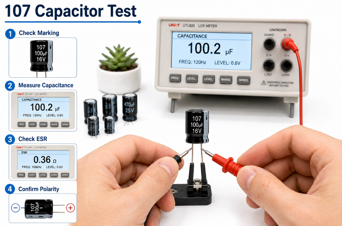
          Difference Between 105, 106 and 107 Capacitor

          The difference between 105, 106 and 107 capacitors is capacitance value. 105 = 1 uF, 106 = 10 uF, and 107 = 100 uF.

          CodeValueConversionCommon Use
          1051 uF1,000 nFSmall decoupling, timing, signal coupling
          10610 uF10,000 nFPower filtering, module decoupling, voltage smoothing
          107100 uF100,000 nFBulk filtering, power input smoothing, energy storage

          Each code increases by 10 times. A 105 capacitor has lower energy storage than a 106 capacitor, while a 107 capacitor has much higher capacitance and may change startup current, charging time and PCB space.

          In repairs, replacing 106 with 105 can reduce filtering capacity and cause ripple or reset problems. Replacing 106 with 107 may work in some power circuits, but it may also affect regulator stability, inrush current and cost.

          What Types of 106 Capacitors Are Common?

          Common 106 capacitors include ceramic, tantalum, aluminum electrolytic and SMD capacitors. They all provide 10 uF capacitance, but their electrical performance, polarity and assembly risks are different.

          • Ceramic type: low ESR, compact size, good for high-frequency decoupling near ICs.
          • Tantalum type: stable capacitance, compact package, usually polarized and sensitive to surge.
          • Electrolytic type: cost-effective for bulk filtering, usually larger and polarized.
          • SMD type: suitable for automated SMT PCB assembly and compact electronic products.
          • Through-hole type: used where manual assembly, mechanical strength or repairability matters.

          For high-density PCB assembly, ceramic and SMD tantalum 106 capacitors are common. For power input filtering or low-cost products, electrolytic capacitors may be selected when board space allows.

          Does a 106 Capacitor Have Polarity?

          A 106 capacitor may or may not have polarity. Ceramic 106 capacitors are usually non-polarized, while tantalum and electrolytic 106 capacitors are usually polarized.

          Non-polarized ceramic capacitors can be mounted in either direction. Polarized capacitors must be installed with the correct positive and negative orientation. Reverse installation can cause leakage current, overheating, short circuit, swelling or complete capacitor failure.

          This is especially important in PCB assembly. Many SMD tantalum capacitors mark the positive terminal with a stripe, while many aluminum electrolytic capacitors mark the negative terminal with a stripe. Because marking rules are not always the same, the datasheet, PCB silkscreen and assembly drawing should be checked before production.

          What Voltage Is a 106 Capacitor?

          A 106 capacitor does not have one fixed voltage. The code 106 only identifies capacitance, while voltage rating depends on the actual capacitor series, package, dielectric material and manufacturer part number.

          MarkingCapacitanceVoltage
          106 6.3V10 uF6.3V
          106 10V10 uF10V
          106 16V10 uF16V
          106 25V10 uF25V
          106 35V10 uF35V
          106 50V10 uF50V

          For stable circuit operation, the voltage rating should be higher than the actual working voltage. In many PCB designs, a practical rule is to choose a capacitor with enough derating margin, especially when ripple, voltage spikes, high temperature or long service life are involved.

          For example, a 10 uF 16V capacitor may be acceptable on a 5V rail, while a 10 uF 6.3V capacitor may be risky if the rail has spikes or poor transient control.

          106 Capacitor, https://www.bestpcbs.com/blog/2026/06/106-capacitor/

          What Is the Tolerance of a 106 Capacitor?

          The tolerance of a 106 capacitor depends on the tolerance letter and component type. Common tolerance codes include J = ±5%, K = ±10% and M = ±20%.

          MarkingValueToleranceNormal Range
          106J10 uF±5%9.5 uF–10.5 uF
          106K10 uF±10%9 uF–11 uF
          106M10 uF±20%8 uF–12 uF

          Tolerance affects the real capacitance value under standard test conditions. For power decoupling, ±10% or ±20% may be acceptable in many circuits. For timing, filtering, sensing or analog applications, tighter tolerance can improve circuit consistency.

          Ceramic capacitors may also lose effective capacitance under DC bias. Therefore, a 10 uF ceramic capacitor may measure lower in actual operation, especially in small packages or higher-voltage circuits.

          What Size Is a 106 Capacitor?

          The size of a 106 capacitor depends on capacitor type, voltage rating, dielectric material, package code and temperature grade. A 10 uF low-voltage SMD ceramic capacitor may be small, while a 10 uF high-voltage electrolytic capacitor may be much larger.

          TypeCommon Size
          SMD ceramic capacitor0402, 0603, 0805, 1206
          SMD tantalum capacitorA, B, C, D, E case
          Aluminum electrolytic capacitor4 mm to 8 mm diameter or larger
          Through-hole ceramic capacitorvaries by voltage and lead spacing

          Higher voltage ratings usually require larger packages. Higher reliability grades, wider temperature ranges and lower ESR versions may also increase size and cost.

          In PCB assembly, the selected capacitor must match the land pattern, height limit, polarity mark, pick-and-place capability and reflow soldering process. A wrong size can cause mounting failure, solder bridging, tombstoning or mechanical interference.

          106 Capacitor Datasheet Overview

          A 106 capacitor datasheet should be reviewed before replacement, purchasing or PCB assembly. The marking 106 confirms 10 uF, but the datasheet confirms whether the part can work safely in the target circuit.

          ParameterTypical Information
          Capacitance10 uF
          Voltage rating6.3V, 10V, 16V, 25V, 35V, 50V
          Tolerance±5%, ±10%, ±20%
          Temperature range-55°C to +85°C or +125°C
          ESRtype and series dependent
          Leakage currentmaterial and voltage dependent
          PackageSMD, radial, axial, case code
          Polaritypolarized or non-polarized
          DielectricX5R, X7R, tantalum, aluminum electrolytic
          ComplianceRoHS, REACH, halogen-free options

          For mass production, the datasheet also helps confirm soldering profile, storage condition, MSL level, shelf life, reel packaging, ripple current and reliability rating.

          A complete BOM should include the manufacturer part number, value, voltage, tolerance, package, dielectric type and approved alternatives. This reduces purchasing mistakes and improves PCB assembly yield.

          Where Is a 106 Capacitor Commonly Used?

          A 106 capacitor is commonly used for power filtering, decoupling, voltage stabilization, ripple reduction and short-term energy storage. Its 10 uF value is large enough for many local power rails while still available in compact packages.

          • MCU power rails: reduces voltage drops and random reset problems.
          • Wireless modules: supports current peaks in Wi-Fi, Bluetooth, GPS and IoT devices.
          • Power supplies: smooths ripple and improves transient response.
          • Sensor circuits: stabilizes analog and digital supply lines.
          • LED drivers: helps reduce flicker and supply fluctuation.
          • Automotive electronics: supports stable operation under vibration and temperature change.
          • Industrial control PCB: improves noise immunity and long-term reliability.

          In PCB layout, a 106 capacitor is often placed near IC power pins, regulators, connectors, sensors and communication modules. Short traces and good grounding improve its filtering effect.

          How to Test a 106 Capacitor with a Multimeter?

          To test a 106 capacitor with a multimeter, first confirm that the circuit is powered off and the capacitor is safely discharged. A 106 capacitor should normally measure close to 10 uF, but the acceptable range depends on its tolerance.

          • Turn off the power first
            Disconnect the device from the power source before testing. Testing a charged capacitor may damage the multimeter or cause unsafe discharge.
          • Discharge the capacitor safely
            Use a suitable resistor to discharge the capacitor before measurement. Do not short the terminals directly, especially for larger capacitors or power supply circuits.
          • Check whether it is still on the PCB
            If the capacitor remains soldered on the PCB, nearby components may affect the reading. For a more accurate result, remove one terminal or test the capacitor after desoldering it.
          • Set the multimeter to capacitance mode
            Select the capacitance function on the multimeter. Then connect the probes to the capacitor terminals. For polarized 106 capacitors, keep the probe direction correct if required by the meter.
          • Compare the measured value with 10 uF
            A normal 106 capacitor should read close to 10 uF. For example, a 106K capacitor has ±10% tolerance, so a reading between 9 uF and 11 uF is usually acceptable.
          • Watch for abnormal readings
            If the reading is 0 uF, extremely low, unstable, or overloaded, the capacitor may be shorted, open, aged, cracked or damaged.
          • Check ESR when capacitance looks normal
            Some failed capacitors still show normal capacitance but have high ESR. In power circuits, high ESR can cause ripple, startup failure, voltage drop or unstable operation.
          • Inspect the capacitor body
            Look for cracks, bulging, leakage, burn marks or broken terminals. Physical damage is often a clear sign that the capacitor should be replaced.

          For PCB repair and production testing, capacitance measurement is only the first check. If the capacitor is used in a power rail, ESR, leakage current, polarity and circuit waveform should also be reviewed.

          106 Capacitor, https://www.bestpcbs.com/blog/2026/06/106-capacitor/

          How to Replace a 106 Capacitor?

          To replace a 106 capacitor, do not choose a new part only by the “106” marking. The replacement must match 10 uF capacitance, voltage rating, tolerance, polarity, package size, capacitor type and circuit requirement.

          • Match the capacitance value
            A 106 capacitor equals 10 uF. The replacement should normally keep the same capacitance unless the circuit design allows a different value.
          • Choose the same or higher voltage rating
            The replacement voltage should be equal to or higher than the original part. For example, a 10 uF 25V capacitor can often replace a 10 uF 16V capacitor if the size and type match.
          • Do not reduce the voltage rating casually
            Replacing a 25V capacitor with a 16V capacitor may reduce reliability, especially in circuits with ripple, voltage spikes or high temperature.
          • Check polarity before soldering
            Ceramic 106 capacitors are usually non-polarized, but tantalum and electrolytic 106 capacitors are usually polarized. Reverse mounting can cause leakage, overheating or failure.
          • Match the package size and footprint
            The new capacitor must fit the PCB pad, height limit and assembly process. A wrong package may cause soldering defects, poor contact or mechanical interference.
          • Confirm the capacitor type
            A 106 ceramic capacitor, 106 tantalum capacitor and 106 electrolytic capacitor may all be 10 uF, but their ESR, leakage current, polarity and stability are different.
          • Check ESR requirements
            Some voltage regulators require a specific ESR range for stable output. Replacing tantalum with ceramic or electrolytic without checking ESR may cause oscillation or unstable voltage.
          • Review temperature and reliability grade
            For industrial, automotive or outdoor PCB applications, choose parts with suitable temperature ratings such as -40°C to +105°C or -55°C to +125°C.
          • Use the full manufacturer part number
            For PCB assembly, the BOM should include the full part number, voltage, tolerance, package, dielectric and approved alternatives. Listing only “106 capacitor” can cause purchasing mistakes.
          • Test the board after replacement
            After soldering, check polarity, solder joints, capacitance and power rail behavior. Then run functional testing to confirm that the circuit starts and operates normally.

          In PCB assembly, a correct replacement should not only match the 106 capacitor value. It should also support the circuit’s voltage, temperature, ESR, layout, sourcing and long-term reliability requirements.

          How to Choose the Right 106 Capacitor for PCB Assembly?

          Choose the right 106 capacitor by matching circuit performance, assembly process, reliability target and sourcing stability. The best capacitor is the one that works reliably after soldering, testing and long-term operation.

          • Confirm circuit function: use ceramic for local decoupling, tantalum for stable compact filtering, and electrolytic for bulk smoothing.
          • Check voltage margin: select a voltage rating higher than the actual rail voltage to reduce failure risk.
          • Review tolerance: choose tighter tolerance for timing, analog and sensitive filtering circuits.
          • Match package: confirm footprint, height, polarity and pick-and-place compatibility.
          • Check ESR: regulator output capacitors may require a specific ESR range for stability.
          • Consider temperature: use wider temperature grades for industrial, automotive and outdoor products.
          • Control sourcing: list full manufacturer part numbers and approved alternates in the BOM.
          • Verify production quality: use AOI, polarity inspection, ICT and functional testing to catch assembly defects.

          For turnkey PCB assembly, the 106 capacitor should be checked during BOM review, incoming inspection and first-article testing. This prevents wrong-value mounting, reverse polarity, soldering defects and field reliability problems.

          106 Capacitor, https://www.bestpcbs.com/blog/2026/06/106-capacitor/

          FAQs About 106 Capacitor

          Q1: Is a 106 capacitor always 10 uF?
          A1: Yes. In the standard three-digit capacitor code, 106 means 10 uF. It also equals 10,000 nF and 10,000,000 pF. However, the number 106 does not show voltage, tolerance, polarity or package size.

          Q2: Is a 106 capacitor the same as a 106 pF capacitor?
          A2: No. A 106 capacitor is not 106 pF. The third digit is a multiplier, so 106 means 10 × 10⁶ pF, which equals 10 uF. This is one of the most common capacitor code reading mistakes.

          Q3: What does 106K mean on a capacitor?
          A3: 106K usually means 10 uF with ±10% tolerance. Under standard test conditions, the measured capacitance may be around 9 uF to 11 uF. For purchasing or PCB assembly, the datasheet should still be checked.

          Q4: What does 106J mean on a capacitor?
          A4: 106J usually means 10 uF with ±5% tolerance. This tolerance is tighter than 106K and can be useful in circuits where capacitance accuracy affects timing, filtering or analog signal behavior.

          Q5: What does 106C capacitor mean?
          A5: A 106C capacitor usually means 10 uF, while “C” may be a voltage code or series code on some SMD tantalum capacitors. Since marking systems vary, confirm the exact voltage and case size from the datasheet.

          Q6: What does 106E capacitor mean?
          A6: A 106E capacitor usually indicates 10 uF, while “E” may represent a voltage code in some capacitor marking systems. It should not be treated as a universal rule because different manufacturers may use different coding methods.

          Q7: Can I replace a 106 16K capacitor with a 106 25K capacitor?
          A7: Usually yes, if the package, polarity, ESR and temperature rating match. Both are 10 uF ±10%, while 25V has a higher voltage rating than 16V. The main concern is whether the new capacitor fits the PCB footprint.

          Q8: Can I replace a 106 25K capacitor with a 106 16K capacitor?
          A8: Only if the circuit voltage is safely below 16V with enough margin. If the original capacitor was 25V, using 16V may reduce reliability under voltage spikes, ripple or high temperature. For production, avoid lowering voltage without approval.

          Q9: Why does my 106 ceramic capacitor measure less than 10 uF?
          A9: Ceramic capacitors, especially MLCC types, can lose effective capacitance under DC bias. A marked 10 uF capacitor may show a lower value in real operation, especially when the package is small or the applied voltage is high.

          Q10: Does a 106 capacitor have positive and negative terminals?
          A10: It depends on the capacitor type. Ceramic 106 capacitors are usually non-polarized, while tantalum and electrolytic 106 capacitors are usually polarized. For polarized capacitors, wrong orientation can cause overheating, leakage or failure.

          Q11: What happens if a 106 capacitor is installed backwards?
          A11: If the capacitor is polarized, reverse installation can cause serious failure. The capacitor may heat up, leak, short circuit or fail during power-on testing. This is a major risk for 106 tantalum capacitors and 106 electrolytic capacitors.

          Q12: Which is better, 106 ceramic capacitor or 106 tantalum capacitor?
          A12: A 106 ceramic capacitor is better for low ESR and high-frequency decoupling. A 106 tantalum capacitor may provide more stable capacitance in compact power rails. The better choice depends on voltage, ESR, polarity, ripple and reliability requirements.

          Q13: Can a wrong 106 capacitor cause PCB failure?
          A13: Yes. A wrong 106 capacitor can cause unstable voltage, ripple, regulator oscillation, startup failure, repeated resets or wireless module dropouts. During PCB testing, engineers should check value, voltage, ESR, polarity, soldering and waveform behavior.

          Q14: What should buyers check before ordering 106 capacitors?
          A14: Buyers should check 10 uF value, voltage rating, tolerance, package, polarity, dielectric type, manufacturer part number, compliance and lifecycle status. For PCB assembly, the BOM should never list only “106 capacitor.”

          Q15: Is a 106 capacitor suitable for industrial PCB assembly?
          A15: Yes, if the part matches the working environment. Industrial PCB projects often require higher voltage margin, wide temperature range, stable sourcing, strong soldering control and strict inspection for long-term reliability.

          Conclusion

          A 106 capacitor has a value of 10 uF, equal to 10,000 nF or 10,000,000 pF. The code 106 only confirms capacitance, while voltage rating, tolerance, polarity, package size, material type, ESR and temperature range must be checked separately. For PCB projects, the right choice should match circuit voltage, filtering purpose, assembly footprint, reliability target and approved sourcing requirements.

          EBest Circuit is a China source factory and global PCB assembly manufacturer. We support BOM review, component sourcing, custom PCB assembly, quality inspection and bulk production for electronic projects using 106 capacitors and related components. Send your BOM, Gerber files and project requirements to sales@bestpcbs.com for a fast quotation and practical assembly support.

          You may also like

          What Is a 105 Capacitor? 105 Capacitor Value, Code and Conversion Guide

          June 11th, 2026

          A 105 capacitor is a capacitor marked with the code 105, and its capacitance is 1 uF. It is the same value as 1,000 nF or 1,000,000 pF. The number 105 is a standard capacitor marking code, not a direct 105 pF value.

          This guide explains the 105 capacitor value, code calculation, voltage rating, polarity, common types, replacement rules and PCB assembly risks. It also helps buyers and engineering teams avoid unclear BOM data, wrong component substitution, package mismatch and quality problems during production.

          105 Capacitor, https://www.bestpcbs.com/blog/2026/06/105-capacitor/

          What Is a 105 Capacitor?

          A 105 capacitor is a capacitor with a capacitance value of 1 uF, equal to 1,000 nF or 1,000,000 pF. The marking 105 is commonly used on ceramic, SMD, film, tantalum and electrolytic capacitors.

          The code follows the standard three-digit capacitor marking rule. The first two digits are 10, and the third digit 5 means five zeros are added in picofarads. So 105 means 10 × 10⁵ pF.

          In PCB assembly, this marking only confirms the nominal capacitance. It does not confirm voltage rating, tolerance, dielectric, package size, polarity or reliability grade. Therefore, two parts marked 105 may not perform the same in a real circuit.

          A 105 capacitor is often used for power decoupling, noise filtering, signal coupling, timing circuits and local energy storage. It is a common value in consumer electronics, industrial control boards, IoT modules, power circuits and communication PCBs.

          What Does 105 Mean on a Capacitor?

          105 on a capacitor means 10 followed by five zeros in pF, so the final value is 1,000,000 pF. After unit conversion, it becomes 1,000 nF or 1 uF.

          The first two digits form the base number, and the third digit is the multiplier. For the capacitor value 105, the base number is 10 and the multiplier is 10⁵. This gives the final capacitance value.

          If a letter appears after 105, it usually shows tolerance. For example, 105J usually means 1 uF with ±5% tolerance, 105K usually means ±10%, and 105M usually means ±20%.

          However, the marking does not tell the full story. A complete part check should include capacitance, voltage, tolerance, package, dielectric type, temperature rating and polarity.

          What Value Is a 105 Capacitor in pF, nF and uF?

          The value of a 105 capacitor is 1,000,000 pF, 1,000 nF or 1 uF. These are the same capacitance value written in three different units.

          CodepFnFuFF
          1051,000,000 pF1,000 nF1 uF0.000001 F

          This conversion is important because different documents use different formats. A schematic may show 1 uF, a supplier page may show 1000 nF, and a calculator may show 1,000,000 pF.

          The 105 capacitor value in nF is 1,000 nF. The 105 capacitor value in uF is 1 uF. The 105 capacitor value in microfarad is also 1 microfarad.

          For purchasing and PCB Assembly, value matching is only the first step. The correct component must also match voltage rating, tolerance, dielectric material, package size, polarity and operating environment.

          How to Read the 105 Capacitor Code?

          The 105 capacitor code is read as 10 × 10⁵ pF, which equals 1 uF. This is the standard three-digit capacitor code value.

          MarkingMeaningValue
          10510 × 10⁵ pF1 uF
          105J1 uF, ±5%1 uF
          105K1 uF, ±10%1 uF
          105M1 uF, ±20%1 uF

          The first two digits show the base number. The third digit shows how many zeros are added after that number in picofarads. This rule is the same method used in many ceramic and film capacitor markings.

          For PCB production, reading the code is not enough. A 105 ceramic capacitor and a 105 tantalum capacitor can have the same capacitance but different polarity, ESR, leakage current, surge tolerance and failure behavior.

          To avoid sourcing errors, the BOM should list manufacturer part number, voltage, tolerance, dielectric, package size and approved alternatives, not only the printed marking.

          How to Calculate the Value of a 105 Capacitor?

          The value of a 105 capacitor is calculated by using this rule: first two digits × 10 to the power of the third digit, measured in pF.

          For 105, the first two digits are 10. The third digit is 5. Therefore, the calculation is 10 × 10⁵ pF, which equals 1,000,000 pF.

          Then convert the unit. Since 1,000 pF equals 1 nF, 1,000,000 pF equals 1,000 nF. Since 1,000 nF equals 1 uF, the final result is 1 uF.

          A 105 capacitor value calculator will show the same result. The key point is that the third digit is a multiplier. This is why 105 does not mean 105 pF.

          105 Capacitor Datasheet Overview

          A 105 capacitor datasheet should be checked for capacitance, marking code, tolerance, voltage rating, dielectric, package size, temperature range, ESR, leakage current, insulation resistance and soldering condition. The code 105 only confirms the value, while the full datasheet confirms whether the part is suitable for the circuit and PCB Assembly process.

          ItemData
          Marking code105, 105J, 105K, 105M
          Capacitance1 uF
          Capacitance in pF1,000,000 pF
          Capacitance in nF1,000 nF
          105J1 uF, ±5%
          105K1 uF, ±10%
          105M1 uF, ±20%
          Voltage rating6.3V, 10V, 16V, 25V, 50V, 100V, 250V, 500V
          DielectricX5R, X7R, Y5V, film, tantalum
          Package0402, 0603, 0805, 1206, radial, axial
          Temperature range-55°C to +85°C or +125°C
          PolarityNon-polar for ceramic and film; polarized for tantalum and electrolytic
          ESRDepends on type, package and frequency
          Leakage currentLower for ceramic and film; higher for some electrolytic types
          Insulation resistanceChecked for leakage and dielectric quality
          Soldering methodSMT reflow, wave soldering or hand soldering
          Common useDecoupling, filtering, coupling, timing, power stability

          Is a 105 Capacitor the Same as a 105 pF Capacitor?

          No, a 105 capacitor is not the same as a 105 pF capacitor. A 105 capacitor equals 1,000,000 pF, while 105 pF is only 105 pF.

          This mistake usually happens when the marking is read as a direct value. In capacitor code rules, the third digit is not a normal number. It is the multiplier that tells how many zeros should be added.

          If a 105 pF capacitor is used instead of a 105 capacitor, the capacitance becomes far too small. This can cause weak filtering, unstable power rails, wrong timing, poor coupling or circuit malfunction.

          In PCB Assembly, this issue often comes from unclear BOM descriptions, manual replacement, mixed component storage or poor incoming inspection. Clear part numbers and first-article inspection can prevent this problem before mass production starts.

          What Are Common 105 Capacitor Types?

          Common 105 capacitor types include ceramic, SMD MLCC, film, tantalum and electrolytic versions. They may share the same value, but they are not automatically interchangeable.

          • 105 ceramic capacitor: Common for bypassing, decoupling and noise filtering.
          • 105 SMD capacitor: Common in SMT Assembly and compact PCB layouts.
          • 105 film capacitor: Better for stable signal, timing and low-loss circuits.
          • 105 tantalum capacitor: Compact and stable, but usually polarized.
          • 105 electrolytic capacitor: Used when larger size and polarity are acceptable.

          The 105 ceramic capacitor value is 1 uF. The 105 SMD capacitor value is also 1 uF. However, the real performance may change with dielectric type, voltage rating, package size and DC Bias.

          For most modern PCB projects, a 105 ceramic capacitor or SMD MLCC is the first choice for local decoupling. For power hold-up, timing, audio or harsh environments, material selection should be reviewed more carefully.

          Does a 105 Capacitor Have Polarity?

          A 105 capacitor may be polarized or non-polarized. Ceramic and film 105 capacitors are usually non-polarized, while tantalum and electrolytic 105 capacitors are usually polarized.

          A non-polar ceramic or film capacitor can be installed in either direction. This makes it suitable for general decoupling, bypassing, AC coupling and signal filtering.

          A polarized tantalum or electrolytic capacitor must follow the positive and negative direction. Reverse installation can cause leakage current, overheating, swelling, short circuit or PCB damage.

          For PCB Assembly, polarity should be confirmed from schematic symbols, PCB silkscreen, component datasheet and placement files. This is especially important when replacing a ceramic capacitor with a tantalum capacitor or when reviewing alternative parts.

          What Voltage Is a 105 Capacitor?

          A 105 capacitor does not have one fixed voltage. Common voltage ratings include 6.3V, 10V, 16V, 25V, 50V, 100V, 250V, 500V or higher.

          Circuit VoltageSuggested Rating
          3.3V6.3V or higher
          5V10V or higher
          12V25V or higher
          24V50V or higher
          48V100V or higher

          The voltage rating should be higher than the actual circuit voltage. Using a lower voltage rating can cause leakage, dielectric breakdown, overheating or shortened service life.

          For ceramic MLCC parts, voltage also affects usable capacitance. A higher-voltage or larger-package capacitor may keep more effective capacitance under DC Bias. This is why two 1 uF parts with different voltage ratings may behave differently in the same circuit.

          For replacement, choose equal or higher voltage rating, matching footprint and suitable dielectric behavior.

          Where Are 105 Capacitors Commonly Used?

          A 105 capacitor is commonly used in power decoupling, noise filtering, signal coupling, timing circuits, sensor modules, communication boards and industrial control PCBs.

          • Power rails: Helps stabilize voltage near ICs and modules.
          • MCU circuits: Reduces switching noise and random reset issues.
          • IoT devices: Supports wireless modules, sensors and low-voltage rails.
          • Audio circuits: Helps with signal coupling and noise reduction.
          • Power supplies: Smooths ripple and transient noise.
          • Automotive electronics: Supports stable operation under temperature and vibration.

          In PCB Assembly, placement affects performance. A 105 SMD capacitor should usually be placed close to the load, with short traces and a clean ground path.

          If the capacitor is placed too far away from the IC or power pin, the filtering effect may be reduced. Good layout practice can improve stability without changing the component value.

          105 Capacitor Application, https://www.bestpcbs.com/blog/2026/06/105-capacitor/

          105 vs 103 vs 104 vs 106 Capacitors: What Is the Difference?

          The difference between 105, 103, 104 and 106 capacitors is the capacitance value. 105 equals 1 uF, 103 equals 0.01 uF, 104 equals 0.1 uF, and 106 equals 10 uF.

          CodepFnFuF
          10310,000 pF10 nF0.01 uF
          104100,000 pF100 nF0.1 uF
          1051,000,000 pF1,000 nF1 uF
          10610,000,000 pF10,000 nF10 uF

          These capacitors are often used together rather than replacing each other. A 104 capacitor may respond better to higher-frequency noise, while a 105 capacitor provides more local energy storage. A 106 capacitor may be used for larger power smoothing.

          Therefore, these codes should not be treated as simple substitutes. The correct value depends on circuit function, noise frequency, load current and stability requirement.

          105 vs 103 vs 104 vs 106 Capacitors, https://www.bestpcbs.com/blog/2026/06/105-capacitor/

          How to Choose the Right 105 Capacitor for Your Circuit?

          Choose the right 105 capacitor by matching capacitance, voltage, tolerance, dielectric, package, polarity, temperature range and circuit function.

          • Confirm the circuit role.
            Decoupling, filtering, coupling and timing circuits have different requirements. A general ceramic capacitor may work for power rails, while a timing circuit may need tighter tolerance and better stability.
          • Select enough voltage margin.
            The voltage rating should be higher than the real working voltage. For a 12V circuit, 25V or higher is often safer than 16V.
          • Check dielectric stability.
            X7R is usually more stable than Y5V. For MLCCs, DC Bias can reduce real capacitance, especially in smaller packages.
          • Match the PCB footprint.
            0402, 0603, 0805 and 1206 packages affect placement accuracy, solder joint quality, voltage options and capacitance stability.
          • Confirm polarity before substitution.
            A non-polar ceramic capacitor should not be replaced with a polarized tantalum capacitor unless the circuit direction and surge condition are reviewed.
          • Control approved alternatives.
            In mass production, use a clear AVL to prevent random changes in brand, dielectric, voltage rating or package.

          For B2B PCB projects, the BOM should include capacitance, voltage, tolerance, dielectric, package and manufacturer part number. This makes sourcing, inspection and assembly more reliable.

          How to Replace a 105 Capacitor Without Causing Circuit Problems?

          To replace a 105 capacitor safely, match 1 uF capacitance, equal or higher voltage rating, same footprint, suitable dielectric, correct tolerance and correct polarity.

          • Identify the original capacitor type.
            Check whether it is ceramic, film, tantalum or electrolytic. The same marking can appear on different capacitor structures.
          • Confirm the real circuit function.
            A capacitor near an IC power pin may be for decoupling. A capacitor in a signal path may affect frequency response. A timing capacitor may affect delay or oscillation.
          • Match voltage and package.
            Do not use a lower voltage rating. Do not choose a different package unless the PCB footprint and soldering process allow it.
          • Check polarity and surge risk.
            Polarized tantalum or electrolytic capacitors must match the PCB direction. Surge current should be reviewed in power circuits.
          • Test the PCB after replacement.
            Check startup behavior, ripple voltage, temperature rise, signal performance and long-term operation.

          This process avoids hidden issues that visual inspection may not reveal. A wrong replacement may pass a simple power-on test but fail later under heat, load or vibration.

          How to Test a 105 Capacitor Before or After PCB Assembly?

          A 105 capacitor can be tested through incoming inspection, capacitance measurement, visual inspection, in-circuit testing and functional PCB testing. The goal is to confirm that the correct 1 uF capacitor is used and that it works safely after assembly.

          • Check the part before PCB Assembly.
            Confirm the reel label, manufacturer part number, package size, voltage rating, tolerance and dielectric type. This prevents wrong reel loading before SMT production starts.
          • Measure capacitance with an LCR meter or capacitance meter.
            A correct 105 capacitor should read close to 1 uF within its tolerance range. For example, a ±10% part may normally measure from 0.9 uF to 1.1 uF under proper test conditions.
          • Check ESR and leakage when required.
            For power filtering, tantalum or electrolytic capacitors, ESR and leakage current may affect circuit stability. Ceramic capacitors usually have low ESR, but the exact value still depends on type, package and frequency.
          • Inspect soldering after PCB Assembly.
            Use AOI or visual inspection to check solder joints, tombstoning, cracks, wrong position, missing parts and polarity errors. This is important for small SMD packages such as 0402, 0603 and 0805.
          • Use ICT or flying probe testing when available.
            ICT and flying probe testing can help detect wrong value, open circuit, short circuit or placement problems. In-circuit readings may be affected by nearby components, so results should be reviewed carefully.
          • Run functional PCB testing.
            Power on the board and check startup stability, ripple voltage, reset behavior, signal performance and temperature rise. This confirms whether the capacitor works correctly in the real circuit.
          • Perform first-article inspection before batch production.
            Before mass PCB Assembly, verify that the correct 105 capacitor is placed at the correct location. This reduces batch failure caused by wrong material loading or incorrect placement files.
          105 Capacitor Test, https://www.bestpcbs.com/blog/2026/06/105-capacitor/

          How to Avoid 105 Capacitor Selection Mistakes in PCB Assembly?

          Avoid selection mistakes by controlling BOM clarity, AVL approval, package footprint, sourcing channel, polarity check and first-article inspection.

          • Do not read the code as 105 pF.
            The correct value is 1 uF, not 105 pF.
          • Do not ignore voltage rating.
            Low voltage margin can lead to leakage, overheating, breakdown or early failure.
          • Do not replace X7R with Y5V blindly.
            The nominal value may be the same, but effective capacitance and temperature stability can be very different.
          • Do not mix polarized and non-polarized parts.
            A reversed tantalum capacitor can fail quickly and damage the PCB.
          • Do not approve unclear substitutes.
            Random alternatives may change package size, dielectric material, tolerance, voltage or reliability grade.
          • Do not skip production inspection.
            Wrong reels, wrong feeder setup and wrong placement can happen during SMT Assembly.

          Most capacitor problems in PCB Assembly are caused by incomplete specifications, not by the capacitor code itself. A clear BOM and controlled inspection process reduce rework, delay and batch failure.

          What Factors Affect 105 Capacitors Price?

          The price of a 105 capacitor is affected by material, voltage rating, tolerance, package size, brand, certification, order quantity and market supply. For PCB Assembly purchasing, the lowest unit price is not always the lowest total cost.

          • Material affects base price.
            Ceramic capacitors are usually lower cost. Film and tantalum versions may cost more because of material structure, stability or application requirements.
          • Voltage rating affects cost.
            A 50V or 100V part usually costs more than a 6.3V or 10V part. Higher voltage can also require a larger case size or better dielectric design.
          • Tolerance affects availability.
            ±10% and ±20% parts are usually easier to source. ±5% parts may cost more, especially when combined with higher voltage or special material.
          • Package size affects sourcing and SMT cost.
            Common packages such as 0603, 0805 and 1206 are usually easier to buy. Very small packages or compact high-voltage parts may cost more during shortages.
          • Brand and certification affect reliability cost.
            Automotive, medical and industrial projects may require traceable brands, stable batches and compliance documents. These parts cost more but reduce rework and field risk.
          • Order quantity affects unit price.
            Full reel orders usually reduce unit cost. Small trial orders, urgent orders or mixed sourcing can increase the total assembly cost.

          For procurement, compare total project cost instead of unit price only. A low-cost capacitor may create higher cost through unstable supply, wrong substitution, SMT rework or field failure.

          FAQs About 105 Capacitors

          Q1: Can a 1 uF capacitor replace a part marked 105?
          A1: Yes, but only when the replacement also matches voltage rating, tolerance, dielectric, package size and polarity. The value alone is not enough for a safe replacement. In PCB Assembly, a correct equivalent should match both electrical and mechanical requirements.

          Q2: Why do some 1 uF capacitors look much smaller than others?
          A2: Size depends on package, voltage rating, dielectric material and capacitor type. A small SMD MLCC may be tiny, while a film or electrolytic capacitor with the same value can be much larger. Higher voltage ratings often require a larger body.

          Q3: Can a 105 capacitor fail even when the value is correct?
          A3: Yes. Failure can happen because of wrong voltage rating, poor soldering, PCB bending, reverse polarity, overheating or DC Bias issues. In production, value matching is only one part of quality control. Assembly process and part selection both matter.

          Q4: Why is DC Bias important for small 1 uF ceramic capacitors?
          A4: DC Bias can reduce the effective capacitance of MLCC capacitors when voltage is applied. A part marked 1 uF may deliver less capacitance in the real circuit. This matters in power rails, filtering circuits and compact PCB designs.

          Q5: Should I choose X7R or Y5V for a 1 uF capacitor?
          A5: X7R is usually preferred when better temperature stability and more reliable capacitance are required. Y5V may be cheaper, but its capacitance can change more with voltage and temperature. For stable PCB performance, X7R is often safer.

          Q6: Why does a 105 capacitor show lower capacitance after soldering?
          A6: Measurement conditions, DC Bias, temperature, tolerance and surrounding in-circuit components can affect the reading. If the capacitor was overheated, cracked or mechanically stressed during assembly, its performance may also change or fail.

          Q7: Can several smaller capacitors replace one 1 uF capacitor?
          A7: Sometimes yes. Several capacitors in parallel can create a combined capacitance close to 1 uF. However, ESR, layout, frequency response and available PCB space must be checked. This substitution should be reviewed before production.

          Q8: Is a 105 capacitor suitable for high-frequency noise filtering?
          A8: It can help, but it is often used together with smaller values such as 0.1 uF or 0.01 uF. Different capacitor values respond better at different frequency ranges. PCB layout and ground path also affect filtering performance.

          Q9: What causes a 105 SMD capacitor to tombstone during SMT Assembly?
          A9: Tombstoning can be caused by uneven solder paste volume, unbalanced pad design, poor placement accuracy or uneven heating during reflow. Small packages are more sensitive. Good stencil design and reflow control help reduce this defect.

          Q10: How should 105 capacitors be stored before assembly?
          A10: They should be stored in a dry, clean and controlled environment according to supplier requirements. Moisture, damaged reels, mixed labels and poor storage control can increase assembly risk. Reel label management is important for mass production.

          Q11: Can a 105 capacitor be used in automotive electronics?
          A11: Yes, but the part should meet the project’s reliability requirements. Automotive projects usually require suitable temperature rating, stable dielectric, traceable sourcing and controlled quality documents. Generic parts should not be used without approval.

          Q12: Why does the same 105 capacitor price vary between suppliers?
          A12: Price can vary because of brand, voltage rating, package, dielectric, stock condition, certification and order quantity. Some low-price parts may not provide stable traceability or consistent production batches, which can increase assembly risk.

          Q13: What should be checked before approving an alternative 105 capacitor?
          A13: Check capacitance, voltage, tolerance, dielectric, package, temperature rating, ESR, polarity, lifecycle status and supplier reliability. For PCB Assembly, the alternative should also fit the footprint and pass first-article inspection.

          Q14: How can EBest reduce capacitor sourcing risk in PCB Assembly?
          A14: EBest can review BOM data, check capacitor specifications, suggest approved alternatives, inspect incoming materials and control SMT Assembly quality. This helps reduce wrong substitutions, package mismatch, polarity errors and production delays.

          Q15: When should I send my BOM for capacitor review?
          A15: Send the BOM before PCB Assembly or before mass production sourcing. Early review helps identify missing voltage ratings, unclear package sizes, risky alternatives and obsolete parts. This reduces rework cost and shortens production preparation time.

          Conclusion

          A 105 capacitor means 1 uF, equal to 1,000 nF or 1,000,000 pF. Correct selection should match voltage rating, tolerance, dielectric, package size, polarity and PCB assembly requirements.

          If your project needs reliable component sourcing and PCBA service, EBest can help review your BOM, source suitable capacitors and complete PCB assembly from our China source factory. For component procurement and PCBA service quotation, contact EBest Circuit today: sales@bestpcbs.com.

          You may also like

          What is the Value of a 101 Capacitor? How to Read it?

          June 10th, 2026

          A 101 capacitor has a capacitance value of 100 pF, which equals 0.1 nF or 0.0001 µF. It is commonly used in RF circuits, timing circuits, oscillator circuits, signal filtering, sensor circuits and some high-voltage PCB applications.

          The marking “101” follows the standard three-digit capacitor code. The first two digits form the base number, and the third digit shows how many zeros to add in picofarads. Therefore, 101 means 10 with one zero, which equals 100 pF.

          However, the code only tells capacitance. Before using or replacing a 101 capacitor, you should also check voltage rating, tolerance, dielectric material, package size, operating temperature and circuit function. These details decide whether the part can work reliably in the actual PCB assembly.

          101 Capacitor, https://www.bestpcbs.com/blog/2026/06/101-capacitor/

          What is the Value of a 101 Capacitor?

          The value of a 101 capacitor is 100 pF. In other units, it equals 0.1 nF and 0.0001 µF. This value is read from the standard three-digit capacitor marking system used on many ceramic capacitors.

          To read it, take the first two digits, “10,” as the base number. Then use the third digit, “1,” as the multiplier. This means one zero is added after 10, giving 100 pF.

          The most common mistake is reading 101 as 101 pF, 101 nF or 101 µF. That is incorrect. In normal capacitor code reading, the correct result is 100 pF, unless the part uses a special manufacturer-specific marking system confirmed by its datasheet.

          What Does 101 Mean on a Capacitor?

          The marking “101” on a capacitor means 100 pF capacitance. It is a coded value, not a direct decimal number. This marking is common on ceramic disc capacitors, MLCC capacitors and some high-voltage ceramic capacitors.

          CodeBaseMultiplierValue
          101101 zero100 pF

          This code does not show whether the capacitor is 50 V, 100 V, 1 kV or 3 kV. It also does not confirm tolerance, dielectric material or package size. Two capacitors may both be marked 101, but they may be designed for very different circuit conditions.

          For correct selection, the marking should be checked together with the part number, datasheet, BOM and circuit position.

          What Is the 101 Capacitor Value in pF, nF and µF?

          The 101 capacitor value is 100 pF, 0.1 nF and 0.0001 µF. These values describe the same capacitance in different units.

          UnitValue
          pF100 pF
          nF0.1 nF
          µF0.0001 µF
          F0.0000000001 F

          In practical PCB circuits, 100 pF is a small capacitance value. It is usually used for high-frequency signals, RF paths, timing adjustment, signal coupling and noise control.

          It should not be confused with 104, which is 0.1 µF. This is a common replacement error because both parts may look like small ceramic capacitors, but their capacitance differs by 1,000 times.

          How to Read a 101 Capacitor Code Correctly?

          A 101 capacitor code is read in picofarads. The first two digits show the starting number, and the third digit shows how many zeros are added. So 101 means 10 × 10¹ pF = 100 pF.

          If a letter appears after the number, such as 101J, 101K or 101M, the letter usually shows tolerance. Tolerance tells how far the actual capacitance may vary from the rated value.

          MarkingValueTolerance
          101J100 pF±5%
          101K100 pF±10%
          101M100 pF±20%

          For RF, oscillator and timing circuits, tolerance can affect performance. A 101J capacitor may be better than 101K when tighter capacitance control is required. For general high-frequency noise filtering, wider tolerance may be acceptable if the circuit design allows it.

          101 Capacitor Code, https://www.bestpcbs.com/blog/2026/06/101-capacitor/

          What Is the Capacitance of a 101 Ceramic Capacitor?

          A 101 ceramic capacitor has a capacitance of 100 pF. Ceramic is commonly used for this value because it supports compact size, low cost, fast response and good high-frequency behavior.

          The actual performance depends on the dielectric material. C0G/NP0 ceramic capacitors offer better stability across temperature, voltage and time. They are suitable for RF circuits, oscillator circuits, timing networks and precision signal paths.

          Other ceramic materials, such as X7R, Y5P or Z5U, may be used in less critical filtering circuits. However, their capacitance can change more under voltage and temperature. For RF tuning, sensor signals or timing-related applications, dielectric selection should be checked carefully.

          101 Capacitor Datasheet Overview

          A 101 capacitor datasheet confirms whether the part can work safely in the target circuit. The marking “101” only means 100 pF. It does not confirm voltage rating, tolerance, dielectric, package size, temperature range, insulation performance or reliability grade.

          ItemCommon Detail
          Capacitance100 pF
          Unit Conversion0.1 nF / 0.0001 µF
          Capacitance Code101
          Tolerance±5%, ±10%, ±20%
          Voltage Rating50 V, 100 V, 500 V, 1 kV, 2 kV, 3 kV
          DielectricC0G, NP0, X7R, Y5P, Z5U
          Temperature Range-55°C to 125°C, series-dependent
          Capacitor TypeMLCC, ceramic disc, high-voltage ceramic
          Mounting TypeSMD, through-hole
          Package Size0402, 0603, 0805, 1206, disc type
          Insulation ResistanceSeries-dependent
          Dissipation FactorSeries-dependent
          Temperature CoefficientDielectric-dependent
          Rated FrequencySeries-dependent
          Operating EnvironmentConsumer, industrial, high-voltage, RF
          ComplianceRoHS, REACH, UL, safety rating when applicable
          Typical UseRF, timing, filtering, coupling, snubber

          What Is the Voltage Rating of a 101 Capacitor?

          The voltage rating of a 101 capacitor is not defined by the “101” code. The code only means 100 pF. The actual voltage may be 50 V, 100 V, 500 V, 1 kV, 2 kV or 3 kV, depending on the capacitor series.

          For low-voltage signal circuits, a 50 V or 100 V part is often enough. For high-voltage supplies, pulse circuits, snubber paths, flyback circuits or surge-related designs, a 101 1kV capacitor or 101 3kV capacitor may be required.

          The safe replacement rule is clear: never use a lower voltage rating than the original capacitor. A higher voltage rating may be acceptable, but only if the package size, lead spacing, dielectric type and circuit performance remain suitable.

          Voltage margin matters in mass production. If the circuit regularly operates close to the capacitor’s maximum rating, long-term reliability may drop, especially under heat, vibration or voltage spikes.

          What Is the Difference Between 101 1kV and 101 3kV Capacitors?

          A 101 1kV capacitor and a 101 3kV capacitor both have 100 pF capacitance. The main difference is voltage withstand capability. A 3kV capacitor is designed for higher electrical stress and usually has stronger insulation or a larger body.

          TypeValueVoltageCommon Use
          101 1kV capacitor100 pF1,000 VHigh-voltage signal, power filtering, snubber circuits
          101 3kV capacitor100 pF3,000 VSurge circuits, pulse circuits, high-voltage applications

          A 3kV capacitor can often replace a 1kV capacitor if physical size and circuit behavior allow. However, a 1kV capacitor should not replace a 3kV part. The lower voltage rating may cause dielectric breakdown, leakage current increase, overheating or early field failure.

          In PCB assembly, this difference should be confirmed during BOM review. If the voltage rating is missing, wrong sourcing becomes more likely.

          Where Is a 101 Capacitor Commonly Used?

          A 101 capacitor is used in circuits that require small capacitance, fast response and high-frequency behavior. Because its value is only 100 pF, it is not used as the main energy storage capacitor.

          Common applications include:

          • RF circuits: used for antenna matching, tuning and signal coupling.
          • Oscillator circuits: helps adjust frequency and timing behavior.
          • Signal filtering: removes high-frequency noise from sensitive lines.
          • Sensor circuits: stabilizes small analog signals and reduces interference.
          • Snubber circuits: helps control voltage spikes in selected high-voltage designs.
          • Communication modules: supports RF paths, clock lines and impedance-sensitive circuits.
          • PCB repair: replaces damaged ceramic capacitors when value, voltage and package match.

          For best performance, placement matters. A 101 capacitor used for filtering should be close to the related IC pin, connector, signal trace or noise source. Long traces add parasitic inductance and reduce filtering effectiveness.

          How to Choose the Right 101 Capacitor Replacement?

          To choose the right 101 capacitor replacement, match capacitance, voltage rating, tolerance, dielectric, package size and circuit function. The marking “101” alone is not enough.

          Use these practical checks:

          • Match capacitance: choose 100 pF, equal to 0.1 nF or 0.0001 µF.
          • Match voltage: use the same or higher rating when size and performance allow.
          • Match tolerance: keep ±5%, ±10% or ±20% according to the circuit requirement.
          • Match dielectric: use C0G/NP0 for RF, oscillator and precision circuits.
          • Match package: confirm SMD size, body diameter or lead spacing.
          • Check circuit role: filtering, timing, coupling and snubber use may require different specifications.
          • Avoid unsafe substitution: do not replace high-voltage or safety-rated parts with common ceramic capacitors.
          • Approve equivalents early: prevent sourcing delays during mass production.

          For PCB repair, the safest method is to identify the original part number or compare it with the schematic and BOM. For PCBA production, replacement should be approved before purchasing.

          How to Test a 101 Capacitor with a Multimeter?

          A 101 capacitor is 100 pF, so the reading is easily affected by test leads and nearby components. A multimeter can be used for quick checking, but an LCR meter is better for accurate testing.

          • Power off the PCB
            Disconnect power before testing. If the 101 capacitor is used in a high-voltage circuit, discharge the circuit first to avoid meter damage or safety risk.
          • Confirm the marking
            Check whether the part is marked 101, 101J, 101K or 101M. The code confirms 100 pF, while the letter shows tolerance.
          • Avoid in-circuit testing when accuracy matters
            Nearby components and PCB traces can affect the result. Remove the capacitor or lift one lead before measuring if the reading must be accurate.
          • Set the meter to capacitance mode
            Use the capacitance function on the multimeter or Fluke 101. Connect the probes to both terminals and wait for the value to stabilize.
          • Keep the leads short
            Long probes add stray capacitance. Keep the leads short and do not touch the metal probe tips during measurement.
          • Check the reading against tolerance
            A good 101 capacitor should read close to 100 pF. 101J is usually ±5%, 101K is usually ±10%, and 101M is usually ±20%.
          • Check for short or open failure
            Near-zero resistance may indicate a short. No capacitance reading or a value far below 100 pF may indicate an open or damaged capacitor.
          • Use an LCR meter for precise testing
            For RF circuits, oscillator circuits, sensor circuits or PCBA inspection, use an LCR meter instead of a basic multimeter.
          • Do not rely only on capacitance
            In high-voltage circuits, also check leakage, insulation resistance and voltage withstand performance.
          • Replace with matching specifications
            If the capacitor is abnormal, replace it with a 100 pF part that matches the original voltage rating, tolerance, dielectric, package size and safety requirement.
          101 Capacitor Test, https://www.bestpcbs.com/blog/2026/06/101-capacitor/

          101 vs 102, 103, 104 and 105 Capacitors: What Is the Difference?

          The difference between 101, 102, 103, 104 and 105 capacitors is capacitance value. They use the same three-digit code rule, but the multiplier is different.

          CodepFnFµF
          101100 pF0.1 nF0.0001 µF
          1021,000 pF1 nF0.001 µF
          10310,000 pF10 nF0.01 µF
          104100,000 pF100 nF0.1 µF
          1051,000,000 pF1,000 nF1 µF

          The key warning is simple: 102 is 10 times larger than 101, 103 is 100 times larger, and 104 is 1,000 times larger. These parts should not be treated as direct replacements.

          In real circuits, this difference can change filtering cutoff, timing delay, RF matching and signal response. Always confirm the schematic or BOM before replacing one code with another.

          101 Capacitors, https://www.bestpcbs.com/blog/2026/06/101-capacitor/

          FAQs About 101 Capacitor Value, Code and Marking

          Q1: Can a 102 capacitor replace a 101 part?
          A1: Usually not. A 101 part is 100 pF, while a 102 capacitor is 1,000 pF. That is 10 times higher. In RF, timing, oscillator or filter circuits, this change may shift frequency, slow response or reduce signal quality. Only use 102 if the circuit design clearly allows it.

          Q2: Can I replace a 101 marking with a 100 pF capacitor?
          A2: Yes, if the other specifications match. The 101 marking is the coded form of 100 pF. The replacement part should also match the original voltage rating, tolerance, dielectric type, package size and safety requirement. For PCBA production, the substitute should be approved before purchasing.

          Q3: Can I use a 104 capacitor instead of a 101 coded part?
          A3: No in most cases. A 104 capacitor is 0.1 µF, while a 101 coded part is 0.0001 µF. The 104 value is 1,000 times larger. This can completely change filtering, timing or RF behavior and may cause circuit malfunction.

          Q4: Why do some 101 capacitors have letters after the number?
          A4: Extra letters usually show tolerance, temperature characteristic or manufacturer series information. For example, 101J often means 100 pF ±5%, and 101K often means 100 pF ±10%. The number shows capacitance, while the letters help confirm accuracy or stability.

          Q5: Do 101 ceramic parts have polarity?
          A5: Most 101 ceramic parts are non-polarized, so they can be installed in either direction. This is different from many electrolytic capacitors. However, non-polarized does not mean universal. The part still must match the correct voltage, dielectric, tolerance and package.

          Q6: Why is one 100 pF ceramic capacitor larger than another?
          A6: Physical size depends on voltage rating, dielectric material, package type and construction. A 3kV 100 pF ceramic capacitor is usually larger than a low-voltage version because it needs stronger insulation and wider spacing. Same capacitance does not always mean same body size.

          Q7: Can 101 capacitors be used in high-voltage circuits?
          A7: Yes, but only if the voltage rating is suitable. A normal low-voltage 100 pF part should not be used in a high-voltage circuit. For high-voltage use, select a 1kV, 2kV or 3kV version according to the circuit requirement.

          Q8: Why does a replacement part fail after assembly?
          A8: Common reasons include wrong voltage rating, wrong dielectric, poor soldering, package mismatch or using a non-approved equivalent. If the original component was a high-voltage or C0G/NP0 part, replacing it with a general ceramic capacitor may cause instability or early failure.

          Q9: Can this 100 pF component be tested while still on the PCB?
          A9: It can be checked quickly in-circuit, but the result may not be accurate. Nearby traces, IC pins and other capacitors can affect the reading. For a reliable test, remove the part or lift one lead. For 100 pF parts, an LCR meter gives better accuracy than a basic multimeter.

          Q10: Why does my multimeter not show 100 pF exactly?
          A10: A 100 pF capacitor has a very small value, so test leads and stray capacitance can affect the reading. Also, tolerance allows variation. For example, 101K may vary by ±10%. A small difference from 100 pF is normal if it stays within the rated tolerance.

          Q11: What happens if the wrong 100 pF part is used in an RF circuit?
          A11: RF circuits are sensitive to capacitance value, dielectric loss and layout. A wrong replacement may cause poor antenna matching, weak signal, frequency shift or unstable communication. For RF use, C0G/NP0 dielectric is often preferred because it gives better stability and lower loss.

          Q12: What should be checked before buying 101 capacitors in bulk?
          A12: Before bulk purchasing, confirm 100 pF value, voltage rating, tolerance, dielectric, package size, approved brand, datasheet and lead time. For PCBA orders, also confirm reel packaging, traceability and substitute part approval. This reduces wrong sourcing and production delays.

          Q13: Is this small-value capacitor suitable for power supply decoupling?
          A13: It can help suppress very high-frequency noise, but it is not enough for normal power rail decoupling. The value is only 100 pF. Most power supply decoupling designs use larger capacitors such as 0.1 µF, 1 µF or 10 µF, depending on the circuit.

          Q14: Why should a PCBA supplier review this capacitor before assembly?
          A14: A PCBA supplier should check it because the marking alone is not enough. The same code may appear on different voltage ratings, dielectrics and packages. BOM review helps prevent wrong part sourcing, assembly mismatch, functional failure and rework cost.

          Q15: What files help a supplier source the correct 100 pF part?
          A15: The best files include the BOM, schematic, PCB layout, part number, datasheet and quantity requirement. If the original part is unavailable, the supplier can use these files to recommend an equivalent component with matching voltage, dielectric, tolerance and package.

          EBest Circuit provides one-stop PCBA service, including BOM review, component sourcing, PCB fabrication, SMT assembly, through-hole assembly and functional testing. For capacitor selection, replacement or custom PCBA production, send your project files to sales@bestpcbs.com for a fast quotation.
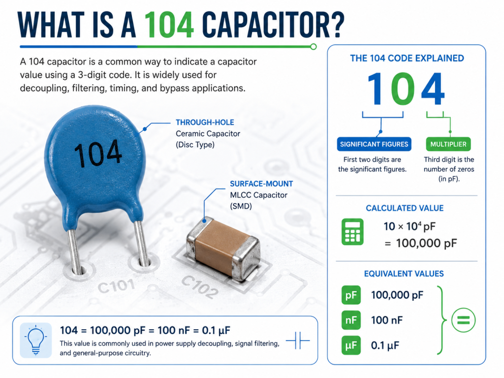
          You may also like

          Tantalum Capacitor vs Electrolytic: Which One Should You Use?

          June 9th, 2026

          When comparing tantalum capacitor vs electrolytic, the key choice is whether your PCB needs compact stability or stronger bulk power filtering. Tantalum capacitors are better for small, stable, low-voltage rails, while aluminum electrolytic capacitors are better for high capacitance, high ripple current, and cost-sensitive power circuits.

          For PCB and PCBA projects, do not select a capacitor by capacitance value only. Check ESR, leakage current, rated voltage, voltage derating, ripple current, temperature grade, package size, polarity, soldering process, and supply stability before approving the part.

          Tantalum Capacitor vs Electrolytic.

          What Is a Tantalum Capacitor?

          A tantalum capacitor is a polarized electrolytic capacitor made with a tantalum anode and tantalum pentoxide dielectric. It is used when a PCB needs high capacitance in a small package.

          Tantalum capacitors are common in compact PCB assemblies, IoT modules, communication boards, medical electronics, portable devices, and stable low-voltage power rails. Their main strengths are small size, stable capacitance, low leakage current, and good performance density.

          The main risk is electrical stress. Tantalum capacitors are sensitive to reverse polarity, voltage spikes, surge current, hot-plug input, and poor derating. They work best on regulated rails, not directly on unstable raw power inputs.

          What Is an Electrolytic Capacitor?

          An electrolytic capacitor is a polarized capacitor used for high capacitance, filtering, smoothing, and energy storage. In most PCB discussions, it usually refers to an aluminum electrolytic capacitor.

          Aluminum electrolytic capacitors are widely used in power supplies, LED drivers, adapters, motor control boards, chargers, inverters, audio circuits, and industrial electronics. Their main strengths are large capacitance, higher voltage options, strong bulk filtering, and lower cost per µF.

          Their limits are also clear. Aluminum electrolytic capacitors are usually larger, and their ESR, leakage current, capacitance stability, and lifetime can be affected by heat, ripple current, electrolyte drying, and long operating time.

          Are Tantalum Capacitors the Same as Electrolytic Capacitors?

          Tantalum capacitors are a type of electrolytic capacitor, but they are not the same as common aluminum electrolytic capacitors. In practical comparison, tantalum capacitor vs electrolytic usually means tantalum capacitor vs aluminum electrolytic capacitor.

          Both types are usually polarized and can be used for filtering, smoothing, decoupling, and energy storage. The differences are material, dielectric structure, electrolyte system, ESR, leakage current, ripple current, size, cost, and failure mode.

          The simple conclusion is this: tantalum is usually smaller and more stable, while aluminum electrolytic is usually cheaper and better for high capacitance and high ripple current applications.

          Tantalum Capacitor vs Electrolytic: What Is Difference?

          The main difference in tantalum capacitor vs electrolytic selection is compact stability versus bulk power capacity. Tantalum capacitors fit compact low-voltage rails, while aluminum electrolytic capacitors fit larger capacitance and power filtering positions.

          The values below are common engineering ranges. Actual values depend on brand, series, voltage rating, case size, temperature grade, and application conditions.

          ParameterTantalumAluminum Electrolytic
          Capacitance Range0.1µF–1,500µF common0.47µF–100,000µF+ common
          Rated Voltage2.5V–50V common6.3V–450V common
          ESR10mΩ–5Ω depending on type20mΩ–several Ω depending on size
          Leakage CurrentOften below 0.01CVOften 0.01CV–0.03CV
          Ripple CurrentTens of mA to several AHundreds of mA to several A+
          Temperature Range-55°C to +125°C common-40°C to +105°C / +125°C common
          LifetimeLong with proper derating1,000–10,000+ hours rated
          Package SizeCompact SMD commonRadial, SMD, snap-in, larger sizes
          Surge ToleranceSensitive to surge currentBetter in many input circuits
          CostHigher per µFLower per µF

          Do not choose by capacitance value alone. A capacitor near an IC pin, DC input, switching regulator, or bulk power rail may require different ESR, ripple current, voltage margin, and package limits.

          Tantalum Capacitor vs Electrolytic: Which One Is More Stable?

          Tantalum capacitors are usually more stable in capacitance, leakage current, and long-term electrical behavior. They are better for stable low-voltage rails, compact layouts, and low-leakage circuits.

          Aluminum electrolytic capacitors are less stable over long use because heat and ripple current can dry the electrolyte and increase ESR. However, they can handle rough input filtering better when rated correctly.

          For stable regulated rails, choose tantalum. For rough input filtering, high capacitance, or high ripple current, choose aluminum electrolytic. This is one of the most important engineering rules in a tantalum capacitor vs electrolytic decision.

          Tantalum Capacitor vs Electrolytic: ESR, Leakage Current and Electrical Performance

          Tantalum capacitors usually have lower ESR and lower leakage current than standard aluminum electrolytic capacitors. This helps reduce ripple and improve local power rail stability.

          ESR affects ripple voltage, heat, transient response, and regulator stability. Lower ESR is not always safer. Some regulators require a specific ESR range, and the wrong capacitor can cause oscillation or unstable startup.

          ParameterTantalumAluminum Electrolytic
          ESR Range10mΩ–5Ω common20mΩ–several Ω common
          Leakage CurrentOften ≤0.01CVOften 0.01CV–0.03CV
          Ripple CurrentTens of mA to several AHundreds of mA to several A+
          Capacitance Tolerance±10%, ±20% common±20% common
          Frequency UseLocal rail filteringBulk smoothing, low-frequency ripple
          Voltage Derating50% margin often used20%–30% margin common
          Temperature Grade+85°C, +105°C, +125°C+85°C, +105°C, +125°C
          Impedance RangeLow to mediumMedium to high

          For replacement, capacitance and voltage are not enough. Check ESR, leakage current, ripple current, impedance curve, temperature rating, and regulator requirements before changing capacitor type.

          Tantalum Capacitor vs Electrolytic

          Tantalum Capacitor vs Electrolytic: Which Is Better for Power Filtering?

          Aluminum electrolytic capacitors are usually better for bulk power filtering and high ripple current. They are common at DC inputs, rectifier outputs, power supply outputs, LED drivers, motor control boards, and DC bus circuits.

          Their larger case size supports higher capacitance and better heat dissipation. If ripple current is too high, the capacitor can overheat, dry out faster, lose capacitance, or fail early.
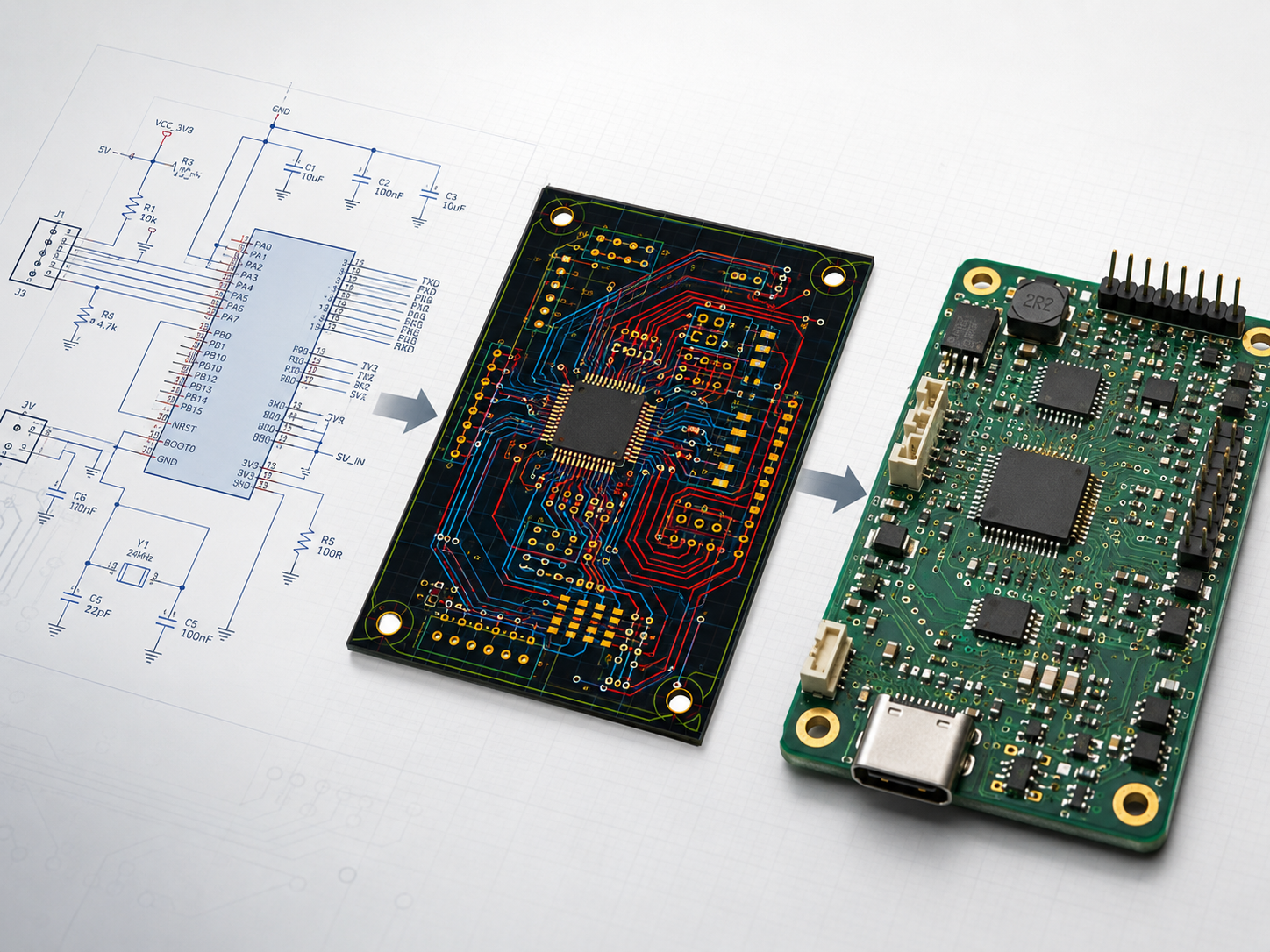
          Use this rule:

          • Choose aluminum electrolytic for bulk capacitance, high ripple current, and lower cost.
          • Choose tantalum for compact size, stable local rails, and lower leakage.
          • Use ceramic capacitors for high-frequency decoupling near IC pins.
          • Check regulator ESR requirements before replacement.
          • Confirm ripple current with temperature rise testing.

          Tantalum Capacitor vs Electrolytic: Which One Lasts Longer?

          Tantalum capacitors can last longer in stable and well-derated circuits because solid tantalum types do not dry out like many aluminum electrolytic capacitors.

          Aluminum electrolytic capacitors can also last long if selected with 105°C or 125°C rating, enough ripple current margin, and reliable brand quality. Their lifetime depends heavily on working temperature, ripple current, and rated hours.

          The failure risks are different. Tantalum is more sensitive to surge current, voltage derating, and polarity mistakes. Aluminum electrolytic is more affected by heat, ripple current, electrolyte drying, and operating hours.

          For stable compact circuits, tantalum usually lasts longer. For power circuits, aluminum electrolytic can be reliable if ripple and temperature margins are correct.

          Tantalum Capacitor vs Ceramic vs Electrolytic: Which One Should You Choose?

          Choose the capacitor by function: ceramic for high-frequency decoupling, tantalum for compact stable rails, and aluminum electrolytic for bulk filtering.

          The values below are common engineering ranges. Actual values depend on dielectric, DC bias, package size, voltage rating, and series.

          ParameterCeramicTantalumAluminum Electrolytic
          Capacitance Range1pF–100µF common0.1µF–1,500µF common0.47µF–100,000µF+ common
          Rated Voltage6.3V–3kV common2.5V–50V common6.3V–450V common
          ESRVery low, mΩ range10mΩ–5Ω common20mΩ–several Ω common
          Leakage CurrentVery lowLowMedium to high
          Temperature Range-55°C to +125°C common-55°C to +125°C common-40°C to +105°C / +125°C common
          DC Bias EffectSignificant in MLCCLowLow
          Ripple CapabilityGood for high frequencyMediumGood for low frequency
          PackageSMD, radial discSMD, molded caseRadial, SMD, snap-in
          Common PositionIC pins, high-frequency nodesLocal regulated railsPower input, bulk filtering

          A practical PCB power network often uses ceramic capacitors near IC pins, tantalum capacitors for local rails, and aluminum electrolytic capacitors for bulk power filtering.

          Tantalum Capacitor vs Ceramic vs Electrolytic

          Can I Use an Electrolytic Capacitor Instead of a Tantalum Capacitor?

          Yes, an aluminum electrolytic capacitor can replace a tantalum capacitor in some circuits, but only if capacitance, voltage rating, ESR, leakage current, ripple current, polarity, size, temperature rating, and lifetime are acceptable.

          This replacement may work in low-frequency filtering or non-critical decoupling. It may fail if the original tantalum capacitor was chosen for low ESR, low leakage, compact size, or stable capacitance.

          Before replacement, check:

          • PCB footprint and height clearance.
          • ESR range for regulator stability.
          • Leakage current for battery or precision circuits.
          • Ripple current rating.
          • Polarity marking.
          • Temperature and lifetime rating.
          • Startup, ripple, and heating after sample testing.

          Do not replace tantalum with aluminum electrolytic only by matching capacitance and voltage.

          Can I Replace an Electrolytic Capacitor with a Tantalum Capacitor?

          Yes, but replacing an electrolytic capacitor with a tantalum capacitor is safe only in selected circuit positions. The circuit should have stable voltage, controlled surge current, correct derating, compatible ESR, and acceptable ripple current.

          This replacement is more suitable after a regulator, LDO, or DC-DC output where the voltage is controlled. It is less suitable at raw DC input, adapter input, rectifier output, or high-ripple power positions.

          Before using tantalum as a replacement, confirm these points:

          • Use enough voltage derating, often 50% or more in sensitive designs.
          • Check surge current and hot-plug risk.
          • Compare ESR with the original circuit requirement.
          • Confirm ripple current rating.
          • Match polarity and footprint.
          • Test startup, ripple voltage, and temperature rise.

          What Are the Risks of Replacing Tantalum and Electrolytic Capacitors Incorrectly?

          Incorrect replacement can cause unstable power output, higher ripple voltage, overheating, short-circuit failure, poor startup, reduced battery life, or early field failure. The biggest mistake is replacing a capacitor only by capacitance and voltage while ignoring ESR, leakage current, ripple current, size, polarity, and circuit position.
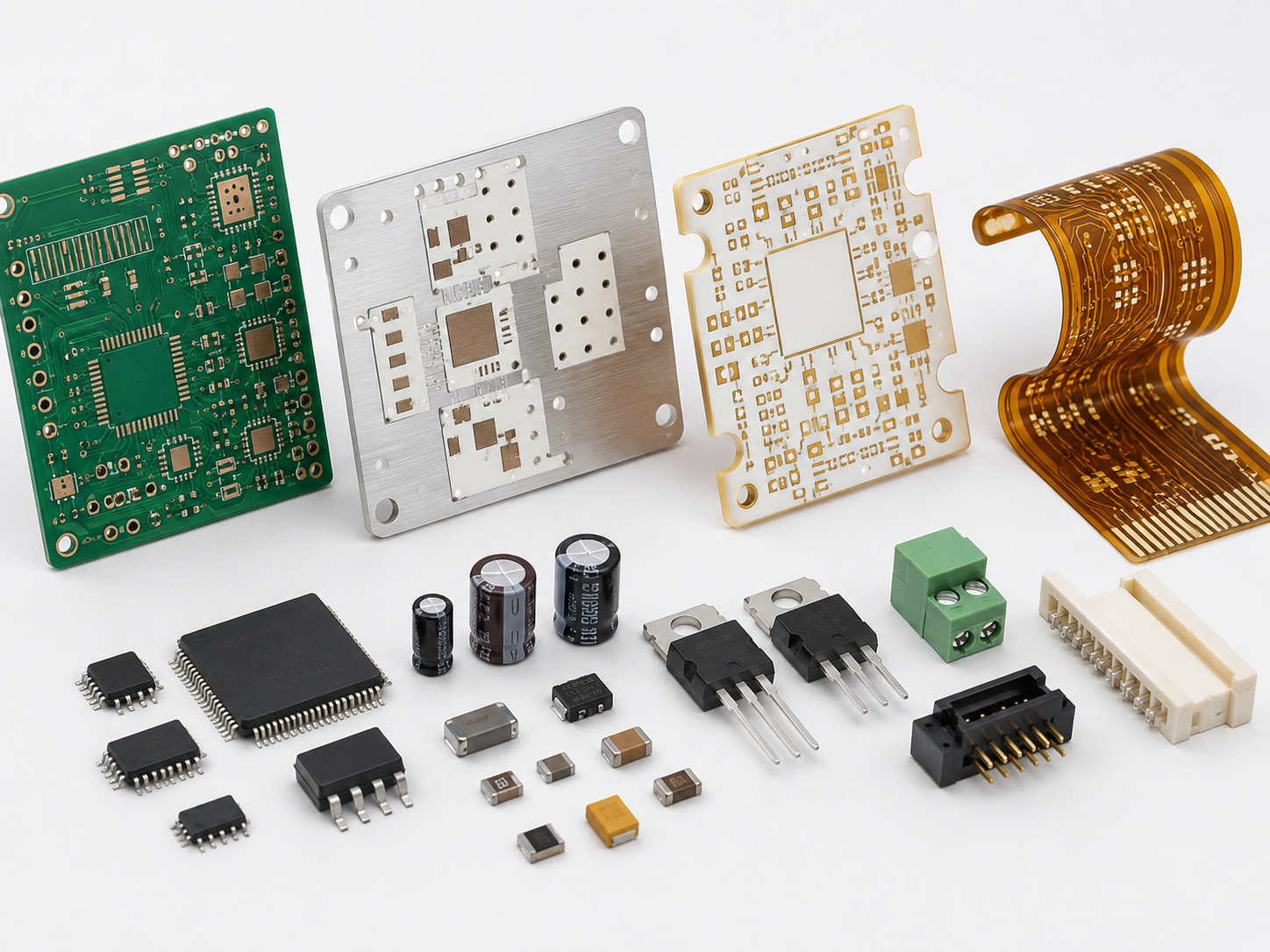
          Common risks include:

          • Wrong ESR causing regulator instability
            Some LDOs and switching regulators require a specific ESR range. If the replacement capacitor has much lower or higher ESR, the output may oscillate, create noise, or fail during startup.
          • Insufficient ripple current causing overheating
            Aluminum electrolytic capacitors usually handle bulk ripple better than standard tantalum capacitors. If a tantalum capacitor is placed in a high-ripple power position without checking the rating, it may overheat or fail early.
          • Higher leakage current affecting battery products
            Replacing tantalum with a standard aluminum electrolytic capacitor may increase leakage current. This can reduce standby time in IoT devices, portable equipment, and low-power control boards.
          • Surge current causing tantalum failure
            Tantalum capacitors are more sensitive to surge current and voltage spikes. Using them at raw DC inputs, adapter inputs, or hot-plug positions without derating can lead to short-circuit failure.
          • Package size causing assembly problems
            Aluminum electrolytic capacitors may be taller or wider than tantalum capacitors. Even if the electrical value matches, the replacement may conflict with enclosure height, nearby components, or automated assembly clearance.
          • Polarity mistakes causing immediate damage
            Most tantalum and aluminum electrolytic capacitors are polarized. Wrong polarity during repair, redesign, or PCBA assembly can cause leakage, heating, venting, or short failure.

          For production projects, do not approve replacement parts from the datasheet only. Confirm the change through sample assembly, power-on testing, ripple measurement, temperature rise testing, and functional verification.

          When Should You Choose a Tantalum Capacitor Instead of an Electrolytic Capacitor?

          Choose a tantalum capacitor when the circuit requires small size, stable capacitance, low leakage current, and reliable local low-voltage filtering. It is a better choice for compact regulated rails, but not for every power input position.
          Good situations include:

          • When PCB space is limited
            Tantalum capacitors provide high capacitance in a compact SMD package. They are suitable for dense PCB layouts, slim products, modules, and boards with strict height limits.
          • When the circuit uses a stable regulated voltage rail
            Tantalum capacitors work well after a DC-DC converter, LDO, or regulated power stage. In this position, voltage spikes and surge current are usually lower than at the raw input.
          • When low leakage current matters
            Tantalum capacitors usually have lower leakage current than many standard aluminum electrolytic capacitors. This is useful for battery-powered devices, standby circuits, sensors, and low-power IoT products.
          • When capacitance stability is important
            Tantalum capacitors offer more stable capacitance than many electrolytic capacitors over normal operating conditions. This helps in timing circuits, local power rails, communication modules, and precision control boards.
          • When long-term drying risk should be reduced
            Solid tantalum capacitors do not dry out like many aluminum electrolytic capacitors. They can be useful in compact products where field repair is difficult.
          • When high-density SMT assembly is required
            Tantalum capacitors are widely available in molded SMD packages. They fit automated SMT assembly better than many through-hole aluminum electrolytic capacitors.
          • When the circuit is a compact communication or IoT module
            Wireless modules, GNSS boards, NB-IoT devices, Bluetooth modules, and control boards often benefit from stable local filtering in limited space.

          Avoid standard tantalum capacitors on raw power inputs unless surge current, hot-plug voltage spikes, reverse polarity risk, and voltage derating are properly controlled.

          When Should You Choose an Aluminum Electrolytic Capacitor Instead of Tantalum?

          Choose an aluminum electrolytic capacitor when the circuit requires high capacitance, higher voltage, stronger ripple current handling, better surge tolerance, or lower cost. It is usually the better choice for power input, bulk filtering, and cost-sensitive PCB or PCBA production.
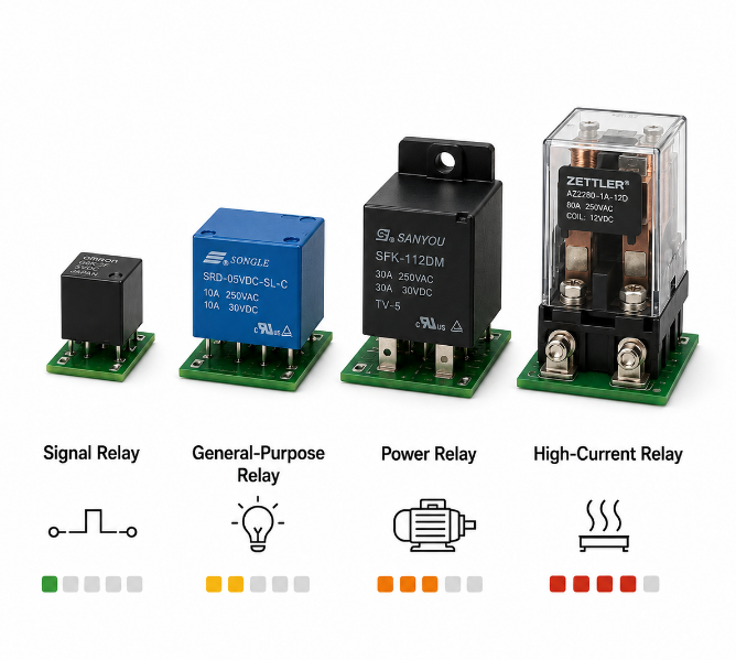
          Good situations include:

          • When the circuit needs large capacitance
            Aluminum electrolytic capacitors are better when the design requires hundreds or thousands of microfarads. They are commonly used for power smoothing, energy storage, and low-frequency ripple reduction.

          • When the voltage rating is higher
            Aluminum electrolytic capacitors are available in wider voltage ranges, commonly from 6.3V to 450V. This makes them more suitable for adapters, power supplies, inverters, and industrial power boards.
          • When ripple current is high
            Power supplies, LED drivers, motor control boards, and DC bus circuits often generate continuous ripple current. Aluminum electrolytic capacitors usually handle this better, especially in larger case sizes.
          • When the capacitor is close to a raw power input
            Input power lines may face hot-plugging, adapter overshoot, inrush current, or voltage spikes. Aluminum electrolytic capacitors are often more practical than standard tantalum capacitors in these positions.
          • When BOM cost matters
            Aluminum electrolytic capacitors usually offer lower cost per µF. For mass production, they are often the better option when PCB space allows a larger component.
          • When the design needs easier sourcing
            Aluminum electrolytic capacitors are widely available in many capacitance, voltage, lifetime, and temperature grades. This helps reduce sourcing risk during bulk production.

          For industrial PCBA production, check rated lifetime, ripple current, ESR, operating temperature, package size, polarity, brand reliability, and supply stability before approval.

          How to Choose the Right Capacitor for Your PCBA Project?

          Choose the right capacitor by matching circuit function, electrical stress, PCB space, operating temperature, lifetime target, cost, and supply stability. The safest method is to start from the capacitor’s job in the circuit, not only from its capacitance value.

          Use this selection guide:

          • For bulk input filtering
            Choose aluminum electrolytic or polymer aluminum capacitors. They are better for large capacitance, low-frequency ripple reduction, and power input smoothing.
          • For compact low-voltage rails
            Choose tantalum or polymer tantalum capacitors when the rail is stable and PCB space is limited. They work well after DC-DC converters, LDOs, and regulated power stages.
          • For high-frequency decoupling
            Choose ceramic capacitors near IC power pins. They provide low impedance at high frequency and help reduce switching noise, digital noise, and local voltage disturbance.
          • For battery-powered products
            Check leakage current first. Tantalum capacitors or selected low-leakage parts may be better than standard aluminum electrolytic capacitors in standby and low-power circuits.
          • For switching regulators
            Check the regulator datasheet for ESR and output capacitance requirements. Wrong ESR may cause oscillation, unstable startup, high ripple, or poor transient response.
          • For high-temperature products
            Use capacitors with proper temperature grade, such as 105°C or 125°C, and confirm rated lifetime. Aluminum electrolytic capacitors need special attention because heat accelerates electrolyte aging.
          • For replacement or BOM alternatives
            Do not approve parts only because capacitance and voltage match. Compare ESR, leakage current, ripple current, tolerance, lifetime, temperature grade, package size, reflow profile, and compliance.

          Before mass production, confirm the capacitor through sample assembly, power-on testing, ripple measurement, temperature rise testing, and functional verification.

          Tantalum Capacitor vs Ceramic vs Electrolytic

          FAQs About Tantalum Capacitor vs Electrolytic

          Q1: How do you identify the polarity of a tantalum capacitor?
          A1: Most SMD tantalum capacitors mark the positive terminal with a stripe, bar, or “+” sign. This is different from many aluminum electrolytic capacitors, where the stripe usually marks the negative terminal. Always confirm the PCB marking before soldering.

          Q2: Why do tantalum and aluminum electrolytic capacitors use different polarity markings?
          A2: The marking convention is different because package structures and industry practices are different. The safest method is not guessing by shape. Check the component datasheet, PCB polarity symbol, and original circuit direction before replacement or repair.

          Q3: Can tantalum capacitors be used in audio circuits?
          A3: Yes, but they are not always the first choice for the audio signal path. Tantalum capacitors can be used in power filtering, but for coupling or tone circuits, check distortion, leakage current, ESR, and sound quality preference before selection.

          Q4: Are tantalum capacitors suitable for high-frequency circuits?
          A4: Tantalum capacitors are useful for local rail filtering, but ceramic capacitors are usually better for very high-frequency decoupling. A common layout uses ceramic capacitors near IC pins and tantalum capacitors slightly farther away for stable bulk support.

          Q5: Do tantalum capacitors need special storage conditions?
          A5: Tantalum capacitors should be stored in a dry, clean, controlled environment and kept away from high humidity, corrosive gas, and excessive heat. For SMT production, storage control helps reduce solderability issues and batch variation.

          Q6: Can old tantalum capacitors be reused from removed circuit boards?
          A6: Reuse is not recommended for production or reliable repair. Old capacitors may have hidden damage from heat, surge stress, soldering, aging, or unknown operating history. For PCBA repair, use new parts from traceable suppliers.

          Q7: What happens if a polarized capacitor is installed backwards?
          A7: Reverse installation can cause high leakage current, heating, venting, short circuit, or complete failure. Tantalum capacitors may fail quickly under reverse voltage, while aluminum electrolytic capacitors may bulge, leak, or vent depending on stress level.

          Q8: Are polymer tantalum capacitors better than standard tantalum capacitors?
          A8: Polymer tantalum capacitors usually have lower ESR, better ripple performance, and improved high-frequency behavior than traditional manganese dioxide tantalum capacitors. They are useful where compact size and low ESR are important.

          Q9: Are polymer aluminum capacitors a better alternative to electrolytic capacitors?
          A9: Polymer aluminum capacitors can be better when the circuit needs low ESR, higher ripple current, and longer stable performance. However, they may have different leakage current, voltage limits, cost, and availability compared with standard aluminum electrolytic capacitors.

          Q10: Can capacitor color or body shape identify the correct replacement?
          A10: No. Color and body shape are not reliable replacement rules. The correct replacement should be based on capacitance, voltage rating, ESR, leakage current, ripple current, temperature grade, package size, and polarity, not appearance.

          Q11: How do you test ESR on a capacitor during repair?
          A11: ESR is usually checked with an ESR meter or LCR meter at the proper test frequency. In-circuit readings may be affected by nearby components, so suspicious results should be confirmed after removing one lead or testing the capacitor separately.

          Q12: Why does a capacitor pass capacitance testing but still fail in the circuit?
          A12: A capacitor can pass capacitance testing but still fail because of high ESR, excessive leakage current, poor ripple rating, bad solder joints, or temperature-related degradation. Capacitance value alone does not prove the part is suitable for operation.

          Q13: What certificates or compliance items should buyers check for capacitors?
          A13: Buyers should check RoHS, REACH, halogen-free status, brand authorization, batch traceability, datasheet consistency, and project-specific compliance. For export PCBA orders, supplier traceability is important for quality control and customer audits.

          Q14: How should capacitor alternatives be approved in a BOM?
          A14: BOM alternatives should be approved by engineering review, not only by purchasing. Compare series, capacitance, voltage, ESR, leakage current, ripple current, package, temperature rating, lifetime, reflow profile, and test results before release.

          Q15: Why do some capacitor replacements work in samples but fail in mass production?
          A15: Sample success does not always prove production reliability. Failures can appear because of batch variation, soldering heat, ripple current, operating temperature, supplier changes, or weak derating margin. Mass production parts should pass controlled PCBA testing.

          Conclusion

          Tantalum capacitors are better for compact, stable, low-voltage circuits, while aluminum electrolytic capacitors are better for bulk filtering, high ripple current, and cost-sensitive production.

          As a one-stop PCBA service provider, EBest supports component selection, BOM review, PCB fabrication, SMT assembly, through-hole assembly, testing, and mass production. For tantalum capacitor vs electrolytic selection, capacitor replacement, or PCBA reliability review, our team can help reduce production risk.

          If you are looking for reliable OEM manufacturing, ODM production, sample development, mass production, or custom engineering solutions, please contact EBest Circuit for technical support and a quote: sales@bestpcbs.com.

          You may also like

          What Value Is a 102 Capacitor? Code, Marking and Replacement Guide

          June 9th, 2026

          A 102 capacitor equals 1000 pF, 1 nF, or 0.001 µF. The number “102” is a standard capacitor code, where “10” is the base number and “2” means two zeros are added in picofarads.

          This guide explains the 102 capacitor value, capacitor 102 marking, ceramic capacitor 102 value, datasheet checks, common types, circuit use, replacement rules, failure problems, cost factors, and supplier selection.

          102 Capacitor

          What Is a 102 Capacitor?

          A 102 capacitor is a capacitor marked with the code “102,” and its capacitance is 1000 pF. This value is also written as 1 nF or 0.001 µF, depending on the unit format used in a datasheet, BOM, or repair document.

          The part is commonly found in ceramic disc capacitors, SMD ceramic capacitors, and small signal filtering circuits. Because the value is small, it is usually used for high-frequency noise control, signal coupling, bypassing, timing, and EMI reduction.

          The key point is simple: 102 is a capacitance code, not a voltage rating or part number. Other specifications must still be checked before replacement or bulk purchasing.

          What Is the 102 Capacitor Value in pF, nF and µF?

          The 102 capacitor value is 1000 pF, 1 nF, or 0.001 µF. These three values are exactly the same capacitance expressed in different units.

          CodepFnFµF
          1021000 pF1 nF0.001 µF

          This conversion matters because different documents may use different units. A datasheet may list 1 nF, a BOM may show 0.001 µF, and the physical capacitor may be marked 102.

          When checking capacitor value 102, always convert the unit before replacement. A wrong unit reading can lead to incorrect filtering, unstable timing, or circuit failure.

          How Do You Read the 102 Capacitor Code?

          The 102 capacitor code is read with the three-digit capacitor marking rule. The first two digits are the significant number, and the third digit is the multiplier based on picofarads.

          For capacitor code 102, the first two digits are 10. The third digit is 2, which means two zeros are added. So the calculation is 10 × 100 pF = 1000 pF.

          In other words, capacitor marking 102 means 1000 pF, not 102 pF. This same rule applies to many common ceramic capacitor codes, such as 101, 103, and 104. Therefore, code reading is the first step before any replacement decision.

          What Does 102 Marking Mean on a Ceramic Capacitor?

          The 102 marking on a ceramic capacitor means the ceramic capacitor value is 1000 pF. It only confirms capacitance and does not automatically confirm voltage rating, tolerance, dielectric material, package size, or safety certification.

          A 102 ceramic capacitor may also include extra letters or numbers. For example, 102K usually means 1000 pF with ±10% tolerance, while markings such as 1kV or 2kV show voltage rating.

          This distinction is important during repair and purchasing. A capacitor 102 may have the same capacitance as another part but a different voltage rating or material. For reliable selection, the marking should be checked together with the datasheet and original circuit requirement.

          102 Capacitor Datasheet Overview

          A 102 capacitor datasheet confirms the real specifications behind the 102 marking. The printed code only shows capacitance, while the datasheet confirms whether the part fits the circuit, soldering process, voltage stress, and quality requirement.

          ParameterWhat to CheckSelection Note
          Capacitance1000 pF / 1 nF / 0.001 µFConfirms the real 102 capacitor value
          Voltage Rating50V, 100V, 1kV, 2kV, or project ratingUse equal or higher voltage than the original part
          ToleranceJ, K, M, or custom toleranceTighter tolerance is better for timing and precision circuits
          DielectricC0G/NP0, X7R, Y5V, Z5UC0G/NP0 is more stable; X7R fits general filtering
          PackageSMD, disc, radial, through-holeMust match PCB pads, lead pitch, and assembly method
          Temperature RangeOperating and storage temperatureImportant for industrial, automotive, and outdoor electronics
          Insulation ResistanceLeakage and insulation dataCritical for high-voltage and low-leakage circuits
          Dissipation FactorLoss performanceLower loss is better for high-frequency signal circuits
          SolderabilityReflow, wave soldering, or hand solderingMust match the actual PCB assembly process
          ComplianceRoHS, REACH, UL, customer standardRequired for regulated markets and export projects
          PackingTape-and-reel, bulk, ammo pack, cut tapeAffects SMT automation, storage, and production efficiency

          For high-voltage, repair, or mass production projects, the datasheet should be checked before sample approval, BOM locking, and bulk purchasing.

          What Are Common Types of 102 Capacitors?

          A 102 capacitor can appear in different package types and voltage ratings, depending on the PCB design, assembly method, and working voltage.

          Common types include:

          • Ceramic capacitor type for filtering, bypassing, and signal circuits.
          • Disc capacitor type for through-hole PCB assembly and high-voltage use.
          • SMD capacitor type for compact electronics and automated SMT production.
          • 1kV rated type for medium high-voltage filtering and coupling.
          • 2kV rated type for stronger insulation and higher-voltage applications.
          • Safety-related ceramic type for approved protection circuits.

          Although these parts may share the same capacitance, they are not always interchangeable. The correct type depends on voltage stress, board space, soldering process, dielectric stability, and safety requirements.

          102 Capacitors

          How Does a 102 Capacitor Work in a Circuit?

          A 102 capacitor stores and releases a small electrical charge to control noise, signal flow, and voltage changes. Because its capacitance is only 1 nF, it responds well to high-frequency behavior rather than large energy storage.

          In a circuit, it may block DC while allowing certain AC signals to pass. It may also shunt high-frequency noise to ground, stabilize switching signals, or help form an RC timing network with a resistor.

          For example, a ceramic part with this value may be placed near an IC pin, sensor line, oscillator circuit, power stage, or communication interface. Its small value makes it useful when the circuit requires fast response and limited capacitance loading.

          What Is the Use of 102 Capacitor?

          A 102 capacitor is commonly used in circuits that require small capacitance and high-frequency response. It appears in both consumer electronics and industrial PCB assemblies.

          Common uses include:

          • Signal coupling in audio, sensor, and communication circuits.
          • Noise filtering in power lines and control boards.
          • High-frequency bypassing near ICs and switching devices.
          • RC timing circuits where 1 nF capacitance is suitable.
          • EMI reduction in selected signal and power paths.
          • High-voltage filtering when using properly rated 1kV or 2kV ceramic parts.
          • Industrial control boards where stable small-value ceramic capacitors are required.

          What Are the Advantages and Limitations of a 102 Capacitor?

          A 102 capacitor is useful for compact filtering and signal control, but it has clear limitations because its capacitance is small.

          Main advantages include:

          • Small size for compact PCB layout.
          • Fast response for high-frequency noise control.
          • Low cost for mass production.
          • Wide availability in ceramic disc and SMD packages.
          • Multiple voltage options for low-voltage and high-voltage circuits.
          • Easy identification through the standard code.

          Main limitations include:

          • Low capacitance, so it cannot replace larger capacitors.
          • Material sensitivity if low-grade ceramic dielectric is used.
          • Possible capacitance drift caused by temperature, aging, or DC bias.
          • Replacement risk if voltage rating and package are ignored.
          • Limited energy storage compared with electrolytic or film capacitors.

          How Can You Replace a 102 Capacitor Correctly?

          A 102 capacitor replacement should match capacitance first, then confirm voltage rating, tolerance, dielectric material, package size, and circuit position. Wrong replacement may cause unstable filtering, changed timing, leakage, or early failure.

          Step 1: Confirm the original marking.
          Check whether the old part is marked 102, 102K, capacitor 102 1kV, capacitor 102 2kV, or another extended code. The 102 marking confirms 1000 pF / 1 nF / 0.001 µF, but other letters and numbers may show tolerance or voltage rating.

          Step 2: Check the circuit function.
          Identify whether the capacitor is used for filtering, coupling, bypassing, EMI reduction, timing, or high-voltage protection. The same capacitance value may require different voltage ratings or dielectric materials in different circuit positions.

          Step 3: Match the voltage rating.
          Choose a replacement with the same or higher voltage rating than the original part. For example, a lower-voltage capacitor should not replace a 1kV or 2kV part in a high-voltage circuit.

          Step 4: Match tolerance and dielectric material.
          Check whether the original part uses J, K, M tolerance or a specific dielectric such as C0G/NP0, X7R, Y5V, or Z5U. Precision, timing, RF, and signal circuits usually require more stable dielectric material.

          Step 5: Confirm package and lead spacing.
          Match the SMD size, disc diameter, radial shape, lead pitch, and PCB pad layout. Even if the capacitance is correct, the part may not fit the board or pass assembly inspection if the package is wrong.

          Step 6: Install and inspect the replacement.
          After soldering, check the solder joints, body cracks, pad condition, and component position. Then measure capacitance when possible and power the circuit carefully to confirm stable operation.

          For repair, sample builds, or mass production, the safest replacement is the same value with equal or higher voltage rating, matching package, and approved datasheet support.

          What Should Be Checked Before Buying 102 Capacitors?

          Before buying 102 capacitors, the buyer should confirm electrical specifications, mechanical fit, compliance, and supply stability. A low price is not useful if the wrong part causes rework or production delay.

          Key checks include:

          • Capacitance value: confirm 1000 pF, 1 nF, or 0.001 µF.
          • Voltage rating: confirm 50V, 100V, 1kV, 2kV, or the required rating.
          • Tolerance: select J, K, M, or the tolerance required by the circuit.
          • Package: confirm SMD size, disc diameter, radial form, or lead pitch.
          • Dielectric: match C0G/NP0, X7R, Y5V, or Z5U according to stability needs.
          • Datasheet: check the approved datasheet before final order.
          • Compliance: confirm RoHS, REACH, UL, or project-specific standards.
          • Packing: choose tape-and-reel, bulk, ammo pack, or cut tape.

          For OEM and ODM manufacturing, the approved BOM should list exact specifications instead of only writing “102 capacitor.”

          How to Test a 102 Capacitor?

          Testing a 102 capacitor should confirm capacitance value, leakage risk, physical condition, and circuit stability. Because the value is only 1000 pF / 1 nF / 0.001 µF, a normal multimeter may not measure it accurately unless it has a small-capacitance range.

          Step 1: Inspect the capacitor body.
          Check for cracks, burn marks, broken leads, oxidation, discoloration, or damaged solder joints. Ceramic capacitors may fail after mechanical stress, overheating, or PCB bending, even when the marking still looks normal.

          Step 2: Measure capacitance with an LCR meter.
          Use an LCR meter or capacitance meter to check whether the reading is close to 1000 pF. The acceptable range depends on tolerance, such as ±5%, ±10%, or ±20%.

          Step 3: Check for short circuit.
          Use resistance mode to confirm the capacitor is not shorted. A shorted capacitor may show very low resistance and can cause power supply protection, signal failure, overheating, or circuit shutdown.

          Step 4: Check leakage or insulation resistance.
          For high-voltage types, leakage and insulation resistance are important. A capacitor may pass a basic capacitance test but still fail under voltage stress if the dielectric insulation is damaged.

          Step 5: Compare with circuit symptoms.
          If the circuit has noise, unstable signal, failed startup, timing error, or repeated fuse/power shutdown, compare the test result with the circuit function. A wrong value or damaged capacitor may affect performance even if it is not fully shorted.

          Step 6: Replace and verify when uncertain.
          For low-cost ceramic capacitors, replacement is often faster than repeated testing. After replacement, check solder joints, power behavior, signal stability, and measured output to confirm the fault is solved.

          For repair, incoming inspection, or production quality control, the best testing method is visual inspection plus LCR measurement, followed by insulation or voltage testing when the capacitor works in a high-voltage circuit.

          102 Capacitor Test

          What Common Failure Problems Occur with 102 Capacitors?

          A 102 capacitor can fail because of overvoltage, ceramic cracking, overheating, poor soldering, moisture, or incorrect replacement. These problems are common in repair work and mass production.

          Common failure problems include:

          • Open circuit caused by cracked ceramic body or damaged internal electrode.
          • Short circuit caused by dielectric breakdown or voltage overstress.
          • Capacitance drift caused by temperature change, aging, or DC bias.
          • Leakage current caused by insulation damage or contamination.
          • Poor solder joint caused by oxidation, wrong soldering profile, or pad pollution.
          • Wrong substitution when the value is confused with 102 pF or 0.01 µF.
          • Mechanical stress failure caused by PCB bending or rough handling.

          Reliable sourcing, correct derating, controlled soldering, and incoming inspection can greatly reduce these risks.

          How Do Cost Factors Affect 102 Capacitor Selection?

          The cost of a 102 capacitor is affected by voltage rating, dielectric material, tolerance, package, certification, and order quantity. A standard low-voltage SMD type is usually cheaper than a high-voltage ceramic disc type.

          For example, a 1kV or 2kV ceramic capacitor usually costs more because it requires stronger dielectric insulation and larger physical spacing. C0G/NP0 parts may also cost more than general-purpose ceramic materials because they provide better capacitance stability.

          In bulk purchasing, the lowest unit price may increase total cost if it causes unstable quality, assembly defects, or field returns. A better strategy is to compare performance, compliance, delivery stability, and approved alternatives together.

          How to Choose a Reliable 102 Capacitor Supplier?

          A reliable 102 capacitor supplier should provide correct value confirmation, datasheets, compliance support, stable quality, and engineering communication. This is especially important for OEM production, ODM projects, PCB assembly, and long-term supply.

          Good supplier selection should focus on:

          • Correct marking review to avoid confusion between 102, 103, and 104.
          • Datasheet support for voltage rating, tolerance, dielectric, and package.
          • Batch consistency for capacitance and soldering performance.
          • Compliance documents for RoHS, REACH, UL, or customer requirements.
          • Alternative part support when the original capacitor is unavailable.
          • Failure review ability for cracked, shorted, or drifting capacitors.
          • Global supply experience from a real China source factory without false overseas branches.

          For overseas buyers, direct factory communication helps reduce sourcing mistakes, sample approval delays, and repeated BOM revisions.

          102 Capacitor

          FAQs About 102 Capacitor

          Q1: Is a 102 capacitor 102 pF?
          A1: No. A 102 capacitor is 1000 pF, not 102 pF. The first two digits are “10,” and the third digit “2” means two zeros are added. Therefore, 102 means 10 × 100 pF = 1000 pF.

          Q2: What is the 102 capacitor value in microfarad?
          A2: The value in microfarad is 0.001 µF. The same capacitance can also be written as 1000 pF or 1 nF. These are only different unit formats for the same capacitor value.

          Q3: What does 102K mean on a capacitor?
          A3: 102K usually means 1000 pF with ±10% tolerance. The “102” shows capacitance, and “K” shows tolerance. If voltage is not printed on the body, check the datasheet, BOM, or original circuit information before replacement.

          Q4: Can I replace a 102 capacitor with a 103 capacitor?
          A4: Usually no. A 102 capacitor is 1 nF, while a 103 capacitor is 10 nF. That is a 10 times higher value. Using 103 instead of 102 may change filtering, timing, signal response, or circuit stability.

          Q5: Can I use a higher-voltage 102 capacitor?
          A5: Yes, a higher-voltage part can often replace a lower-voltage one if the package size, lead spacing, dielectric type, and board clearance are suitable. For example, a 2kV part may replace a 1kV part when space allows.

          Q6: Why does a 102 ceramic capacitor look different from another 102 capacitor?
          A6: Two capacitors with the same 1 nF value may look different because of voltage rating, dielectric material, tolerance, and package type. A 2kV ceramic part is usually larger than a low-voltage SMD capacitor.

          Q7: What should I check in a 102 capacitor datasheet?
          A7: Check capacitance, voltage rating, tolerance, dielectric material, package size, temperature range, insulation resistance, and compliance. The datasheet confirms whether the part fits the circuit, while the marking only confirms capacitance.

          Q8: Is a 102 capacitor polarized?
          A8: Most ceramic capacitors with this value are non-polarized and can be installed in either direction. However, the actual circuit position, package type, and product design should still be reviewed before replacement or assembly approval.

          Q9: How do I test a 102 capacitor with a multimeter?
          A9: A normal multimeter may not measure small capacitance accurately. Use an LCR meter or capacitance meter. The expected reading should be around 1000 pF, with variation depending on tolerance such as ±5%, ±10%, or ±20%.

          Q10: Why does a 102 capacitor fail in a power supply?
          A10: Common causes include overvoltage, heat, poor derating, soldering stress, ceramic cracking, and wrong replacement. In high-voltage circuits, using a lower-voltage substitute may cause leakage, breakdown, or short-circuit failure.

          Q11: What does 102 mean on an SMD capacitor?
          A11: If an SMD capacitor is marked 102, it usually means 1000 pF / 1 nF. Many small SMD capacitors have no visible marking, so the reel label, BOM, or component datasheet should be checked before use.

          Q12: What tolerance should I choose for a 102 capacitor?
          A12: Common tolerance codes include J = ±5%, K = ±10%, and M = ±20%. Precision circuits should use tighter tolerance, while general filtering circuits may accept wider tolerance if the design allows it.

          Q13: Can a 102 capacitor be used for EMI filtering?
          A13: Yes, this value can help reduce high-frequency noise. However, EMI performance also depends on placement, grounding, voltage rating, safety approval, and PCB layout. For mains-related circuits, use the correct safety-rated capacitor.

          Q14: What should I send to a supplier when buying 102 capacitors?
          A14: Send the value 1 nF, voltage rating, tolerance, package type, dielectric material, quantity, compliance requirement, and application. For PCB assembly, also provide the BOM, PCB files, approved manufacturer list, and sample requirement.

          Q15: Is 102 capacitor suitable for mass production?
          A15: Yes, this component value is common in mass production. For stable production, confirm approved manufacturer, package size, voltage rating, tolerance, packing method, datasheet, and incoming quality inspection standard before bulk purchasing.

          Conclusion

          A 102 capacitor equals 1000 pF, 1 nF, or 0.001 µF. The code is easy to read, but correct selection depends on voltage rating, tolerance, dielectric material, package size, datasheet confirmation, soldering process, and real circuit function.

          For replacement, match the original capacitance first, then confirm voltage and package details. For purchasing, avoid selecting parts by price alone. Stable quality, approved datasheets, batch consistency, and engineering support are more important for OEM manufacturing, ODM production, sample development, and mass production.

          If you are looking for reliable component sourcing and PCB assembly service, please contact EBest Circuit for technical support and a quote: sales@bestpcbs.com.

          You may also like

          High Pin MCU Selection Guide for Reliable OEM Electronics Projects

          June 5th, 2026

          A high pin MCU is a microcontroller selected for projects that need many usable I/O pins, multiple communication interfaces, large peripheral mapping flexibility, and stable PCB assembly in compact or function-dense electronics. In practical engineering, the term usually refers to high-pin-count microcontrollers in packages such as LQFP, QFN, BGA, TFBGA, or similar formats, often used in industrial control, automotive electronics, medical devices, smart instruments, communication equipment, robotics, and customized OEM products.

          Choosing a high pin MCU is not only about finding the device with the largest number of pins. The real decision involves usable GPIO count, pin multiplexing, ADC channels, PWM outputs, memory size, clock speed, package type, PCB routing density, soldering yield, long-term availability, firmware scalability, and test coverage. Official MCU product selectors commonly include pin count and package filters, which shows how important packaging and I/O planning are during component selection.

          What Is a High Pin MCU?

          A high pin MCU is a microcontroller with a larger package pin count than entry-level devices, giving designers more physical connections for sensors, displays, buttons, relays, motors, communication buses, memory interfaces, and control signals. In many projects, engineers start considering a high-pin-count MCU when a 32-pin, 48-pin, or 64-pin device cannot support the required number of interfaces without excessive I/O expansion.

          There is no single universal threshold for “high pin.” In embedded electronics, 80-pin, 100-pin, 128-pin, 144-pin, 176-pin, and 208-pin MCUs are often treated as higher-pin-count options, depending on the product category. For example, some STM32 families are offered across several package sizes, and one STM32F103 family datasheet describes package options from 36 pins to 100 pins, with peripheral availability depending on the selected device.

          High Pin MCU

          Why Does Pin Count Matter in MCU Design?

          Pin count affects more than the number of wires connected to the chip. It influences the whole electronic design, including schematic planning, PCB layer count, assembly process, firmware structure, test strategy, and future product upgrades.

          A high pin MCU can reduce the need for external I/O expanders, multiplexers, decoders, or secondary controllers. This can simplify firmware timing, reduce bus latency, and improve control precision. It also gives engineers more freedom to separate critical signals, add debug access, reserve spare pins, and support product variants from the same hardware platform.

          However, pin count must be reviewed together with the actual available GPIO. Some pins may be shared with oscillator circuits, boot mode settings, reset, power pins, analog references, debug interfaces, or special peripheral functions. A larger package does not always mean every pin is freely available as GPIO. TI engineering support also notes that the number of GPIOs depends on the MCU package, which is a key detail buyers and designers should check before final part approval.

          How Does a High Pin MCU Work?

          A high pin MCU works like any microcontroller: it integrates a CPU core, memory, timers, communication interfaces, analog blocks, clock circuits, interrupt controllers, and GPIO ports into one programmable device. The difference is that a larger package exposes more of those internal resources to the outside world.

          Most MCU pins support multiplexed functions. One physical pin may serve as GPIO, UART TX/RX, SPI signal, I2C line, ADC input, PWM output, timer capture input, CAN signal, Ethernet function, LCD segment, or external memory interface. The firmware configures the selected function through registers or software libraries.

          High Pin MCU Package Types

          Package selection has a direct impact on PCB design, SMT assembly, inspection, repairability, and product size. For high-pin-count MCUs, the most common package families include LQFP, TQFP, QFN, BGA, TFBGA, and LFBGA. ST’s product families, for example, include package variants such as LQFP and BGA across different pin-count options, while MCU suppliers often provide package-based ordering codes to distinguish pin count and memory configuration.

          High Pin MCU Package Types
          Package TypeCommon UseMain StrengthEngineering Consideration
          LQFP / TQFPIndustrial control, instruments, automotive modulesEasier visual inspection and reworkLarger PCB footprint
          QFNCompact devices, cost-sensitive boardsSmall size and good thermal pathRequires accurate stencil and solder control
          BGAHigh-density electronics, advanced productsStrong routing density and compact footprintNeeds X-ray inspection and controlled PCB design
          TFBGA / LFBGASpace-limited high-performance productsHigh pin density in small areaHigher PCB fabrication and assembly control needed
          WLCSPMiniaturized consumer or wearable productsExtremely compactMore demanding assembly and board reliability review

          For many industrial and OEM projects, LQFP remains a practical choice because it is easier to inspect, easier to prototype, and friendlier for low-to-mid-volume manufacturing. BGA becomes attractive when the product needs high density, small size, or advanced signal routing.

          How Many Pins Does a High Pin MCU Usually Have?

          A high pin MCU may have 80, 100, 128, 144, 176, 208, or more package pins. The exact number depends on the MCU family, package type, target application, and peripheral set.

          A 100-pin MCU is common in industrial controllers, display modules, motor control boards, and mid-range embedded systems. A 144-pin or 176-pin MCU is often selected when the design needs external memory, LCD control, many timers, parallel interfaces, Ethernet, multiple ADC inputs, or many product-variant options. Larger BGA packages may be used when the product requires higher performance and compact routing.

          The important question is not “How many package pins are available?” The better question is “How many pins remain usable after power, ground, boot, reset, debug, oscillator, analog reference, and dedicated peripheral pins are assigned?”

          High Pin MCU vs Low Pin MCU: What Is the Difference?

          A low pin MCU is suitable for simple control tasks, small sensors, basic power modules, compact IoT nodes, LED drivers, button panels, and cost-sensitive products. A high pin MCU is better for products with many interfaces, complex control logic, multiple sensors, display functions, industrial communication, or expansion requirements.

          Comparison ItemLow Pin MCUHigh Pin MCU
          Typical Pin Count8–64 pins80–208+ pins
          PCB SizeSmallerLarger or denser
          Design FlexibilityLimitedStronger
          Peripheral AccessFewer exposed functionsMore exposed functions
          Firmware ExpansionMore constrainedEasier to scale
          Assembly DifficultyLowerMedium to high
          BOM CostUsually lowerUsually higher
          Best FitSimple embedded productsComplex OEM electronics

          A low pin MCU can still be powerful, especially in compact products. A high pin MCU is selected when the product architecture needs more hardware access, not simply because a larger chip looks more advanced.

          Key Parameters to Check Before Choosing a High Pin MCU

          A reliable MCU selection process starts with the product architecture, not with the part number. Engineers should review the full signal map before approving the MCU.

          ParameterWhy It MattersWhat to Check
          Usable GPIO CountDetermines whether all signals can connect directlyExclude power, ground, reset, oscillator, boot, and debug pins
          Pin MultiplexingPrevents function conflictsConfirm UART, SPI, I2C, CAN, ADC, PWM, USB, Ethernet, and LCD mapping
          Flash MemorySupports firmware size and future updatesLeave enough margin for feature expansion
          RAMAffects real-time data handlingCheck buffers, RTOS, communication stacks, display data
          ADC / DAC ChannelsImportant for sensors and analog controlConfirm resolution, sampling speed, reference design
          Timer / PWM ResourcesNeeded for motors, LEDs, power controlCheck channel quantity and timer grouping
          Package TypeAffects PCB and assemblyMatch PCB supplier and SMT capability
          Operating TemperatureImportant for industrial and automotive useReview standard and extended temperature grades
          Lifecycle StatusReduces sourcing riskCheck active, NRND, EOL, and second-source options

          The best high pin MCU is the one that matches the product’s electrical, mechanical, firmware, supply chain, and production requirements at the same time.

          Common Applications of High Pin MCU

          High pin MCU devices are widely used in electronics that need many signals and stable embedded control. NXP describes its general-purpose Arm Cortex-M MCU portfolio as covering performance, efficiency, scalability, software tools, and development boards, which reflects how MCU selection is now closely tied to complete project development.

          ApplicationWhy High Pin MCU Is Used
          Industrial control boardsHandles sensors, relays, displays, communication, alarms, and safety signals
          Automotive electronicsSupports control modules, lighting control, motor control, sensors, and CAN communication
          Medical devicesConnects sensors, displays, buttons, alarms, memory, and communication interfaces
          Smart instrumentsSupports LCD, keypad, ADC channels, calibration, and data logging
          RoboticsControls motors, encoders, sensors, communication, and safety feedback
          Energy systemsManages voltage sensing, current sensing, relays, protection, and communication
          Communication equipmentSupports control logic, status monitoring, ports, and management interfaces
          LED control systemsProvides PWM channels, thermal feedback, dimming control, and fault detection

          For OEM and ODM projects, a high pin MCU can support multiple product versions on one hardware platform. This helps reduce redesign work when customers need different interface options.

          PCB Design Rules for High Pin MCU Projects

          High pin MCU PCB design needs careful planning because more pins usually mean higher routing density, more signal groups, and greater risk of layout congestion. The layout should start from power integrity, clock stability, programming access, and critical signal grouping.

          Power and Ground Planning

          Place decoupling capacitors close to each MCU power pin. Use short return paths, clean ground reference, and proper power plane design. High-pin-count MCUs often have multiple VDD and VSS pins, and every power group should be treated as part of the system’s reliability foundation.

          Clock and Reset Routing

          Crystal and clock traces should be short, clean, and protected from noisy switching signals. Reset and boot pins should include stable pull-up or pull-down design according to the MCU datasheet.

          Peripheral Grouping

          Group related pins logically. Motor control, ADC sensing, communication buses, display signals, and debug interfaces should be arranged to reduce trace crossing and improve testability.

          BGA Escape Routing

          If the MCU uses BGA packaging, PCB layer count, via-in-pad, microvia, solder mask registration, and X-ray inspection must be reviewed early. BGA packages can improve density, but they also require stronger PCB fabrication and assembly process control.

          Reserved Pins

          Reserve extra pins when the product roadmap is not fixed. Spare GPIO can support future sensors, new communication functions, production testing, or customer-specific versions.

          Manufacturing and Assembly Risks of High Pin MCU

          High pin MCU assembly requires accurate solder paste control, component placement, reflow profile management, and post-assembly inspection. For fine-pitch QFP, common process concerns include solder bridging, insufficient solder, lead coplanarity, and alignment. For BGA, hidden solder joints make X-ray inspection important.

          IPC-A-610 provides acceptance requirements for electronic assemblies, while IPC J-STD-001 covers requirements for soldered electrical and electronic assemblies. These standards are commonly referenced when defining workmanship, soldering quality, inspection expectations, and production acceptance levels.

          Moisture sensitivity also matters. IPC/JEDEC J-STD-020 is used to determine moisture-sensitivity-level classification for surface mount devices so they can be packaged, stored, and handled properly before reflow. This is especially important for high-pin-count ICs exposed to lead-free reflow temperatures.

          Testing Methods for High Pin MCU Boards

          Testing should be planned before PCB layout is finalized. A complex MCU board without test points can be difficult to debug, inspect, and validate during mass production.

          Test MethodPurpose
          AOIChecks visible solder joints, polarity, placement, and obvious defects
          X-rayInspects BGA solder joints, hidden pads, voiding, and internal solder defects
          ICTTests electrical connectivity, shorts, opens, and basic component values
          Flying ProbeUseful for prototypes and small batches when fixtures are not ready
          Functional TestConfirms firmware, I/O behavior, communication, sensor reading, and output control
          Boundary ScanUseful when supported by the MCU and connected ICs
          Programming TestVerifies firmware loading, boot mode, debug access, and memory response
          Burn-In / Aging TestSupports reliability screening for demanding products

          For high pin MCU projects, functional testing should include every important I/O group. A board may pass power-on testing but still fail in the field if one peripheral group is not verified under realistic load.

          Common Failure Modes in High Pin MCU Projects

          High pin MCU failures often come from system-level mismatches rather than the MCU itself. The most useful review is a combined engineering, PCB, firmware, and production review.

          Failure ModeTypical CausePractical Solution
          Missing GPIO during firmware developmentPin multiplexing conflictBuild a pin assignment table before schematic approval
          Communication failureWrong alternate function, pull-up issue, or layout problemValidate pin mapping and signal integrity
          ADC instabilityNoisy reference, poor grounding, long analog tracesSeparate analog routing and improve filtering
          Solder bridgingFine pitch, excessive paste, stencil issueOptimize stencil aperture and reflow profile
          BGA open jointWarpage, poor pad design, placement issueUse X-ray inspection and controlled PCB stack-up
          Boot failureWrong BOOT pin state or unstable resetAdd correct pull resistors and reset timing review
          Field resetPower dip, EMI, watchdog misconfigurationImprove power integrity and firmware fault handling
          Sourcing delayMCU lifecycle or allocation issueApprove alternatives early and monitor stock risk

          A high pin MCU should not be selected only by schematic needs. It should also be reviewed for manufacturability, testing, and long-term supply.

          How to Choose the Right High Pin MCU for Your Project?

          The right selection process begins with a complete I/O and peripheral map. Engineers should list every required signal, assign the preferred peripheral function, check package availability, and leave enough margin for future changes.

          Step One: Define the Product Architecture

          List sensors, outputs, communication interfaces, displays, memory, debug ports, power-control signals, safety signals, and factory test pins.

          Step Two: Build a Pin Assignment Table

          Create a table that includes signal name, MCU pin, alternate function, voltage level, pull-up/pull-down requirement, test point, and firmware owner.

          Step Three: Check Peripheral Conflicts

          A high pin MCU may still have conflicts when several functions share the same internal resources. Check timer channels, DMA mapping, ADC groups, communication ports, and interrupt priorities.

          Step Four: Review PCB Routing

          Confirm whether the selected package can be routed within the planned PCB size and layer count. A lower-cost MCU may increase PCB complexity if the package is too dense or poorly matched to the board.

          Step Five: Confirm Supply Chain Status

          Check lifecycle, stock, lead time, authorized channels, alternative models, and package compatibility. High pin MCU shortage or EOL risk can affect the whole product schedule.

          Step Six: Validate with Prototype Testing

          Prototype testing should include firmware, thermal behavior, EMC preparation, programming process, and full I/O verification.

          pcb design for high pin mcu

          Cost Factors for High Pin MCU Projects

          The total cost of a high pin MCU project is not limited to chip price. It includes PCB layer count, assembly yield, inspection method, test fixture, firmware development, procurement risk, and lifecycle management.

          Cost FactorHow It Affects the Project
          MCU Unit PriceHigher pin count and larger memory usually increase component cost
          Package TypeBGA and fine-pitch packages may require stronger assembly control
          PCB Layer CountMore pins can require more routing layers
          PCB TechnologyMicrovias, via-in-pad, impedance control, and fine lines increase fabrication cost
          Test FixtureMore I/O may require more test points and fixture complexity
          Firmware WorkMore peripherals increase configuration and validation time
          InspectionBGA packages may require X-ray inspection
          Supply ChainLimited stock or long lead time can increase procurement cost
          CertificationMedical, automotive, and industrial products may need stronger documentation

          A good cost strategy is not always choosing the smallest or cheapest MCU. In many OEM projects, a slightly larger MCU can reduce external components, simplify firmware, improve product scalability, and lower redesign cost.

          Procurement Tips for High Pin MCU Buyers

          Buyers should evaluate high pin MCU sourcing with both commercial and technical logic. A part may look available during prototype development but become difficult to source when the project moves into batch production.

          Before purchase, confirm the exact part number, package code, temperature grade, memory size, packaging method, MSL level, date code, traceability, and compliance documents. For products sold into Europe or other regulated markets, RoHS compliance may be required; the European Commission states that RoHS currently restricts ten substances in electrical and electronic equipment.

          Procurement teams should also avoid approving only one MCU model when the product has long lifecycle expectations. A better approach is to prepare at least one compatible alternative, review pin-to-pin migration possibility, and reserve firmware flexibility where possible.

          For OEM/ODM programs, early BOM review is valuable. It helps identify high-risk part numbers, long lead time components, end-of-life risk, and possible engineering alternatives before production is delayed.

          Quality Control for High Pin MCU Assembly

          Quality control starts before SMT production. The engineering team should review the datasheet, footprint, stencil design, PCB finish, reflow profile, handling condition, and inspection standard.

          For LQFP or TQFP packages, AOI and visual inspection can verify many solder joint conditions. For QFN and BGA packages, hidden joints require stronger process validation. X-ray inspection is often used for BGA and bottom-terminated components because external visual inspection cannot confirm every solder joint.

          Production control should include incoming component verification, MSL management, solder paste inspection, placement accuracy, reflow profiling, AOI, X-ray where needed, programming, and functional testing. For higher-reliability products, traceability records should connect the MCU batch, PCB lot, solder paste batch, production date, operator station, inspection result, firmware version, and shipment record.

          What Should Be Checked Before Placing a High Pin MCU Order?

          Before placing an order, engineers and buyers should align the technical and commercial requirements in one checklist.

          Checklist ItemRequired Review
          Exact MCU Part NumberConfirm series, memory, package, temperature grade
          Pin AssignmentConfirm no conflict between GPIO and alternate functions
          PCB FootprintMatch datasheet land pattern and assembly capability
          Package HandlingCheck MSL, storage, baking, and reflow requirement
          Firmware AccessConfirm SWD, JTAG, UART boot, or programming method
          Test PointsReserve access for key power rails and I/O signals
          ComplianceConfirm RoHS, REACH, and customer-specific requirements
          LifecycleCheck active status, lead time, and alternatives
          Production TestDefine programming, ICT, functional test, and inspection plan
          TraceabilityConfirm batch record, date code, and inspection documentation

          The safest time to solve MCU risk is before PCB layout is finalized. Once the PCB is already fabricated, every pin conflict becomes more expensive.

          FAQs

          What does high pin MCU mean?

          A high pin MCU means a microcontroller with many package pins and more exposed I/O resources. It is used when a product needs many sensors, outputs, communication interfaces, displays, test points, or future expansion options. The term is practical rather than fixed by one industry standard.

          Is a high pin MCU the same as a high GPIO MCU?

          Not always. Package pin count and usable GPIO count are related, but they are not identical. Some pins are used for power, ground, reset, oscillator, debug, boot, analog reference, or dedicated functions. Always check the datasheet and build a usable pin table.

          When should I choose a 100-pin MCU?

          A 100-pin MCU is suitable when 64-pin devices cannot provide enough GPIO, peripheral mapping, ADC channels, PWM outputs, or communication interfaces. It is common in industrial control boards, display control products, smart instruments, and mid-complexity OEM electronics.

          When should I choose a 144-pin MCU or larger?

          A 144-pin or larger MCU is useful when the product needs external memory, LCD control, Ethernet, many timers, multiple communication buses, or a scalable hardware platform. It is also helpful when one PCB must support several customer-specific versions.

          Is BGA better than LQFP for high pin MCU?

          BGA is better for compact, high-density routing, but LQFP is easier to inspect, prototype, and rework. For many industrial products, LQFP is practical. For smaller and more advanced electronics, BGA may be the better choice if the factory has proper PCB and X-ray capability.

          Does a high pin MCU increase PCB cost?

          It can increase PCB cost if the package requires more layers, finer traces, smaller vias, or via-in-pad design. However, it may reduce external components and redesign work. The final cost depends on the whole product architecture, not the MCU alone.

          Conclusion

          A high pin MCU is the right choice when a product needs many direct connections, flexible peripheral mapping, stable control functions, and enough room for future expansion. The strongest design approach is to check usable GPIO, package type, pin multiplexing, PCB routing, assembly process, test coverage, and supply chain status together.

          For engineers, the key selection advice is simple: do not choose by pin count alone. Build a complete signal map, confirm every alternate function, reserve test points, and validate the design through prototype testing. For buyers, the practical procurement advice is to confirm lifecycle, packaging, compliance, traceability, and alternative supply before volume production begins.

          You may also like

          100k Ohm Resistor Color Code: How to Read and Verify It?

          June 2nd, 2026

          The 100k ohm resistor color code is one of the most common resistor markings used in electronics, PCB assembly, repair work, prototyping, and circuit learning. For a standard 4-band resistor, the color code is Brown, Black, Yellow, and Gold. This represents 100,000 ohms with a tolerance of plus or minus 5%.

          For engineers, technicians, students, and buyers, knowing how to read this value correctly helps prevent wrong component placement, unstable circuit behavior, and unnecessary troubleshooting. A 100k resistor may look simple, but the wrong tolerance, package, power rating, or SMD code can still affect the final product.

          100k Ohm Resistor Color Code

          What Is the 100k Ohm Resistor Color Code?

          The 100k ohm resistor color code is the color-band marking used to identify a resistor with a resistance value of 100,000 ohms, also written as 100 kΩ. For the most common 4-band resistor, the color code is:

          Brown – Black – Yellow – Gold

          BandColorMeaning
          1st BandBrownFirst digit: 1
          2nd BandBlackSecond digit: 0
          3rd BandYellowMultiplier: ×10,000
          4th BandGoldTolerance: ±5%

          The calculation is:

          10 × 10,000 = 100,000 ohms = 100kΩ

          The gold band means the actual resistance may vary by ±5%. In real use, a 100kΩ resistor with gold tolerance can measure between 95kΩ and 105kΩ and still be acceptable.

          Why Is the 100kΩ Resistor Color Code Important?

          A 100kΩ resistor is widely used in bias circuits, pull-up and pull-down networks, voltage dividers, sensor inputs, feedback circuits, RC timing circuits, and low-current signal paths. Because it is a common value, it is also easy to confuse with nearby values such as 10kΩ, 120kΩ, 150kΩ, or 1MΩ.

          Reading the color bands correctly helps engineers, technicians, students, and buyers avoid wrong-value placement during prototyping, repair, PCB assembly, and incoming material inspection.

          Small axial resistors are commonly marked by color bands under the international resistor color-code system. Depending on the precision level, a resistor may use 3-band, 4-band, 5-band, or 6-band markings. The reading direction usually starts from the band closest to one end of the resistor body.

          How Do You Read a 4-Band 100k Ohm Resistor?

          A 4-band resistor uses two significant digits, one multiplier, and one tolerance band. For a standard 100kΩ ±5% resistor, the color bands are:

          Brown – Black – Yellow – Gold

          PositionColorValue
          First digitBrown1
          Second digitBlack0
          MultiplierYellow×10,000
          ToleranceGold±5%

          The first two bands form the number 10. The third band, yellow, adds the multiplier ×10,000. The final result is:

          10 × 10,000 = 100,000Ω

          The fourth band shows tolerance. Gold represents ±5%, brown represents ±1%, red represents ±2%, green represents ±0.5%, and silver represents ±10%.

          What Is the 5-Band 100k Resistor Color Code?

          A 5-band resistor gives three significant digits instead of two. This format is common on precision resistors. For a 100kΩ 5-band resistor, the first four bands are usually:

          Brown – Black – Black – Orange

          The fifth band shows tolerance.

          BandColorMeaning
          1st BandBrownFirst digit: 1
          2nd BandBlackSecond digit: 0
          3rd BandBlackThird digit: 0
          4th BandOrangeMultiplier: ×1,000
          5th BandBrown / Red / Green / GoldTolerance

          The calculation is:

          100 × 1,000 = 100,000Ω

          ResistanceTolerance5-Band Color Code
          100kΩ±1%Brown – Black – Black – Orange – Brown
          100kΩ±2%Brown – Black – Black – Orange – Red
          100kΩ±0.5%Brown – Black – Black – Orange – Green
          100kΩ±5%Brown – Black – Black – Orange – Gold

          If the resistor has six bands, the sixth band usually indicates temperature coefficient, often shown in ppm/°C. This matters in precision analog circuits, measurement devices, automotive electronics, and temperature-sensitive designs.

          100k Ohm Resistor Color Code Chart

          Resistor TypeColor CodeResistanceTolerance
          4-band 100kΩBrown – Black – Yellow – Gold100kΩ±5%
          4-band 100kΩBrown – Black – Yellow – Brown100kΩ±1%
          5-band 100kΩBrown – Black – Black – Orange – Brown100kΩ±1%
          5-band 100kΩBrown – Black – Black – Orange – Red100kΩ±2%
          5-band 100kΩBrown – Black – Black – Orange – Green100kΩ±0.5%
          5-band 100kΩBrown – Black – Black – Orange – Gold100kΩ±5%

          For quick checking, remember this:

          4-band 100kΩ = Brown Black Yellow + tolerance

          5-band 100kΩ = Brown Black Black Orange + tolerance

          How Is a 100kΩ Resistor Different from 10kΩ, 1kΩ, and 1MΩ?

          Many mistakes happen because similar resistor values use similar-looking color bands. The multiplier band is often the key difference.

          how to reading resistor color codes
          Resistance4-Band Color CodeCalculation
          1kΩBrown – Black – Red – Gold10 × 100
          10kΩBrown – Black – Orange – Gold10 × 1,000
          100kΩBrown – Black – Yellow – Gold10 × 10,000
          1MΩBrown – Black – Green – Gold10 × 100,000

          The first two colors may stay the same, while the multiplier changes. That is why the third band is critical when reading 4-band resistors.

          For 100kΩ, the multiplier band must be yellow in a standard 4-band code. If the third band is orange, the part is 10kΩ. If it is green, the part is 1MΩ.

          Where Are 100kΩ Resistors Commonly Used?

          A 100kΩ resistor is useful when a circuit needs a high resistance value with low current flow. It is not usually selected for power-heavy circuits. Instead, it is common in signal control, biasing, logic-level management, and sensing applications.

          ApplicationHow 100kΩ Is Used
          Pull-up / pull-down circuitsSets a default logic state with low current consumption
          Voltage dividersHelps scale voltage for ADC, MCU, or sensing circuits
          Transistor biasingSets base or gate bias in low-current circuits
          RC timing circuitsWorks with capacitors to create delay or filtering behavior
          Sensor circuitsSupports signal conditioning and input impedance control
          Feedback networksHelps define gain, reference level, or response behavior
          Battery-powered devicesReduces standby current in low-power designs

          In PCB design, 100kΩ resistors often appear around microcontrollers, op-amps, MOSFET gates, reset pins, feedback loops, and analog input circuits.

          What Materials Are Used for 100kΩ Resistors?

          A 100kΩ resistor can be made with different resistor technologies. The right type depends on tolerance, stability, noise, cost, package size, and operating environment.

          Resistor TypeTypical StrengthCommon Use
          Carbon FilmEconomical and widely availableGeneral-purpose circuits
          Metal FilmBetter tolerance and lower noiseAnalog and precision circuits
          Thick Film Chip ResistorCost-effective for SMT assemblyConsumer, industrial, and control boards
          Thin Film Chip ResistorHigh precision and stable performanceMeasurement, medical, instrumentation
          High-Voltage ResistorBetter voltage handlingPower supplies, sensing, industrial equipment

          For most PCBA projects, a 100kΩ resistor is selected as a through-hole axial resistor or an SMD chip resistor. Through-hole parts often use color bands. SMD resistors usually use printed numeric codes, reel labels, or manufacturer part numbers.

          How Do You Identify a 100kΩ SMD Resistor?

          SMD resistors usually do not use color bands. Instead, they often use numeric markings. Common SMD markings for 100kΩ include:

          MarkingMeaningResistance
          10410 + 4 zeros100,000Ω
          1003100 × 1,000100,000Ω
          1002100 × 10010,000Ω
          10510 + 5 zeros1,000,000Ω

          For a 3-digit code, the first two digits are significant figures, and the third digit is the multiplier. So 104 means 10 × 10,000 = 100kΩ.

          For a 4-digit code, the first three digits are significant figures, and the fourth digit is the multiplier. So 1003 means 100 × 1,000 = 100kΩ.

          On modern small packages such as 0402 or 0201, markings may be absent. In that case, the BOM, reel label, manufacturer datasheet, and measurement process become more important.

          How Do You Test a 100kΩ Resistor?

          The simplest way to verify a 100kΩ resistor is to use a digital multimeter in resistance mode.

          1. Set the multimeter to resistance mode.
          2. Touch the probes to both resistor leads or pads.
          3. Read the measured value.
          4. Compare the result with the tolerance range.

          For a 100kΩ ±5% resistor, the acceptable range is:

          95kΩ to 105kΩ

          For a 100kΩ ±1% resistor, the acceptable range is:

          99kΩ to 101kΩ

          When the resistor is already soldered onto a PCB, the reading may be affected by parallel circuit paths. If the measured value looks lower than expected, it does not always mean the resistor is defective. For accurate confirmation, remove one leg from the circuit or check the schematic first.

          How Do You Test a 100kΩ Resistor?

          What Common Mistakes Happen When Reading a 100kΩ Resistor?

          The most common mistake is reading the resistor from the wrong direction. The tolerance band is usually separated from the other bands by a slightly larger gap or positioned closer to one end. If the resistor is read backward, the value can be misidentified.

          MistakeResult
          Confusing yellow and orange100kΩ may be mistaken for 10kΩ
          Confusing brown and red tolerance±1% may be mistaken for ±2%
          Reading a 5-band resistor as 4-bandPrecision value may be decoded incorrectly
          Measuring in-circuitParallel components may lower the reading
          Ignoring power ratingThe resistor may overheat in operation
          Using only color bands for procurementPackage, tolerance, and voltage rating may be missed

          A good engineering habit is to confirm the resistor value from three sources when possible: color code, BOM, and measurement.

          What Failure Problems Can Happen with 100kΩ Resistors?

          A 100kΩ resistor usually carries low current, but failures can still occur in real products. In PCB assembly and field operation, the issue is often not the nominal value itself. It is usually wrong placement, wrong tolerance, environmental stress, contamination, or circuit-level overstress.

          Failure ModePossible CausePractical Check
          Wrong resistance valueMixed reels, wrong BOM, manual placement errorCheck BOM, reel label, AOI, and DMM reading
          Open circuitMechanical crack, thermal stress, poor solder jointInspect solder joints and measure continuity
          Resistance driftHeat, humidity, aging, material instabilityCompare with tolerance and datasheet limits
          Noise in analog signalLow-grade resistor technologyUse metal film or thin film type
          OverheatingPower or voltage rating exceededRecalculate power dissipation
          Leakage or unstable readingFlux residue or contaminationClean PCB and inspect surface insulation

          For mass production, the best control method is not only checking the color bands. It is to lock the approved part number, verify reel labels, use first-article inspection, and apply electrical testing when the circuit is value-sensitive.

          How Should Engineers Choose a 100kΩ Resistor?

          Selecting a 100kΩ resistor should not stop at resistance value. The circuit requirement decides the final specification.

          ParameterWhat to Confirm
          Resistance100kΩ / 100,000Ω
          Tolerance±5%, ±1%, ±0.5%, or ±0.1%, depending on circuit need
          Power Rating1/8W, 1/4W, 1/2W, or SMD package power rating
          PackageAxial, 1206, 0805, 0603, 0402, 0201
          Temperature CoefficientImportant for precision and temperature-sensitive circuits
          Voltage RatingImportant in high-voltage dividers and industrial circuits
          Resistor TechnologyCarbon film, metal film, thick film, thin film
          ComplianceRoHS, REACH, AEC-Q200 when required
          Operating EnvironmentTemperature, humidity, vibration, coating, and lifespan

          For a simple pull-up resistor, ±5% may be enough. For analog feedback, sensing, medical electronics, or industrial measurement circuits, ±1% or better is often more suitable.

          What Should Buyers Check Before Ordering 100kΩ Resistors?

          For purchasing teams, the color code is useful for identification, but it is not enough for sourcing. A purchase specification should include the complete electrical and mechanical requirement.

          • Exact resistance value: 100kΩ
          • Tolerance requirement
          • Package size or through-hole body size
          • Power rating
          • Temperature coefficient
          • Voltage rating
          • Resistor technology
          • Manufacturer part number
          • Approved alternative brands
          • RoHS / REACH compliance
          • AEC-Q200 requirement for automotive projects
          • Packaging format: tape and reel, cut tape, bulk, ammo pack
          • MOQ, lead time, and lot traceability
          • Required test report or CoC if needed

          In OEM and ODM production, resistor substitution should be controlled. A 100kΩ part from another brand may look equivalent, but tolerance, TCR, voltage rating, noise, and reliability grade can still affect performance.

          FAQs

          What is the color code for a 100k ohm resistor?

          The standard 4-band 100k ohm resistor color code is Brown – Black – Yellow – Gold. Brown means 1, black means 0, yellow means multiply by 10,000, and gold means ±5% tolerance. The final value is 100,000 ohms, or 100kΩ.

          What is the 5-band color code for a 100kΩ resistor?

          A common 5-band 100kΩ resistor uses Brown – Black – Black – Orange – Brown for ±1% tolerance. The first three bands form 100, the orange band means ×1,000, and the final brown band means ±1%. Other tolerance colors may be used depending on the part.

          Is 100kΩ the same as 100,000 ohms?

          Yes. 100kΩ means 100 kilo-ohms, and one kilo-ohm equals 1,000 ohms. So 100kΩ equals 100,000 ohms. In schematics and BOMs, it may also appear as 100K, 100 k, 100kR, or 100,000Ω.

          What does the gold band mean on a 100k resistor?

          The gold band usually means the resistor has ±5% tolerance. For a 100kΩ resistor, ±5% means the real measured value can range from 95kΩ to 105kΩ. This is acceptable for many general-purpose circuits, but precision circuits may need tighter tolerance.

          How can I tell the reading direction of a resistor?

          Start from the band closest to one end of the resistor body. The tolerance band is often slightly separated from the other bands and may be gold or silver. If the resistor has five or six bands, check the spacing carefully before decoding the value.

          Can I measure a 100kΩ resistor while it is still on the PCB?

          You can measure it, but the result may not be accurate because other components may be connected in parallel. If the measured value is lower than expected, check the schematic first. For reliable confirmation, lift one resistor lead or remove the part from the board.

          What is the SMD code for a 100kΩ resistor?

          A common 3-digit SMD marking for 100kΩ is 104. This means 10 followed by four zeros, or 100,000 ohms. A common 4-digit marking is 1003, meaning 100 × 1,000. Very small SMD resistors may have no visible marking.

          Is a 100kΩ resistor suitable for pull-up circuits?

          Yes, 100kΩ can be used as a pull-up or pull-down resistor when low current consumption is important. However, it may be too weak for noisy environments or fast signal transitions. Engineers should check the input leakage current, signal speed, and circuit noise margin.

          Does resistor color code show power rating?

          No. The color bands show resistance value and tolerance, and sometimes temperature coefficient on 6-band resistors. Power rating is determined by the resistor size, construction, package, and datasheet. A 100kΩ resistor must still be checked for power and voltage stress.

          Why does my 100kΩ resistor measure 98kΩ?

          A 98kΩ reading can be normal if the resistor tolerance allows it. For a ±5% 100kΩ resistor, any value from 95kΩ to 105kΩ is acceptable. For a ±1% resistor, 98kΩ would be outside the normal range and should be checked further.

          What resistor type is best for precision 100kΩ circuits?

          For precision analog, sensing, or feedback circuits, metal film or thin film resistors are usually better choices. They offer tighter tolerance, lower noise, and better stability than many general-purpose carbon film or thick film parts. Always confirm TCR and long-term drift in the datasheet.

          Can a wrong 100kΩ resistor cause a PCB assembly failure?

          Yes. A wrong value can affect timing, bias voltage, feedback ratio, signal level, and standby current. In mass production, even a small value mistake may create unstable startup, inaccurate sensing, or functional test failure. BOM control and first-article inspection help reduce this risk.

          Conclusion

          The 100k ohm resistor color code is simple once the band logic is clear. For a common 4-band resistor, Brown – Black – Yellow – Gold means 100kΩ ±5%. For a 5-band precision resistor, Brown – Black – Black – Orange gives the 100kΩ value, while the final band defines tolerance.

          For engineering use, do not judge the part only by color. Confirm tolerance, package, power rating, voltage rating, temperature coefficient, resistor technology, and compliance requirements. For purchasing and production, use the BOM, approved manufacturer list, reel label, inspection process, and electrical testing together to reduce wrong-value risks.

          If you are working on OEM manufacturing, ODM production, sample development, mass production, or custom engineering projects, resistor selection should be tied to the circuit function, product reliability target, and assembly quality plan.

          You may also like