

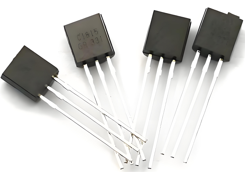
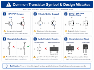
In modern electronics, the transistor symbol is one of the most frequently used elements in circuit schematics. It appears in almost every design, from simple switching circuits to complex multi-layer PCB systems. While the physical transistor is a semiconductor device, the symbol is what engineers rely on to interpret how that device behaves inside a circuit.
For engineers, designers, and even procurement teams reviewing schematics, understanding transistor symbols is essential. It helps you quickly identify signal paths, determine control logic, and verify whether a circuit is designed correctly. Without this knowledge, even a well-documented schematic can become difficult to interpret.
Transistor Symbol Meaning, Function, Types & How to Read it?
What Is a Transistor Symbol in Electronics?
A transistor symbol is a simplified graphical representation used in circuit diagrams to show how a transistor connects and behaves within an electronic system. It does not show the physical shape of the device. Instead, it highlights electrical terminals and signal flow direction so engineers can quickly understand circuit behavior.
In practical design work, the transistor symbol becomes a universal language. Whether you are reviewing a schematic or debugging a PCB, this symbol helps you identify amplification stages, switching paths, and control nodes without ambiguity.
At its core, the symbol communicates three essential things:
- The number of terminals (typically three)
- The direction of current flow
- The type of transistor (NPN or PNP)
Because modern electronics rely heavily on transistor-based circuits, understanding this symbol is not optional. It is a foundational skill for anyone working in PCB design, embedded systems, or hardware development.
Is a Transistor Current or Voltage?
A transistor is both a current-controlled device and a voltage-controlled device, depending on the type and how it is used in a circuit. This dual nature is what makes it extremely versatile in electronics.
For BJT (Bipolar Junction Transistor) devices:
- The transistor is mainly current-controlled
- A small base current controls a larger collector current
- This behavior is ideal for amplification
For FET (Field Effect Transistor) devices:
- The transistor is mainly voltage-controlled
- The gate voltage controls current flow between drain and source
- This makes it efficient for switching applications
In real-world PCB applications, engineers often choose between these behaviors depending on the design goal. If precise current amplification is needed, BJT is preferred. If low power control is required, FET becomes the better choice.
Transistor Symbol Function in Circuit Design
The transistor symbol plays a critical role in circuit design because it defines how signals move and interact. It is not just a drawing. It is a compact representation of functionality.
In circuit schematics, the symbol helps engineers:
- Identify switching points in digital circuits
- Understand amplification paths in analog designs
- Trace signal direction quickly during debugging
- Design logic gates and control systems
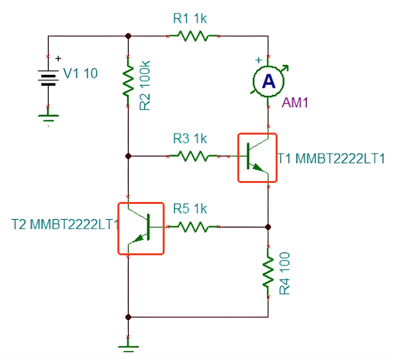
For example, in a switching circuit, the transistor symbol clearly shows whether current will flow when a signal is applied. In an amplifier, it helps determine gain direction and biasing requirements.
Without a clear symbol, interpreting a circuit would be slow and error-prone. That is why every PCB layout begins with a well-structured schematic using standard transistor symbols.
What Does a Transistor Symbol Represent in a Circuit?
A transistor symbol represents the internal structure and electrical behavior of the device. Even though the internal semiconductor layers are not shown, the symbol gives enough information to understand how it works.
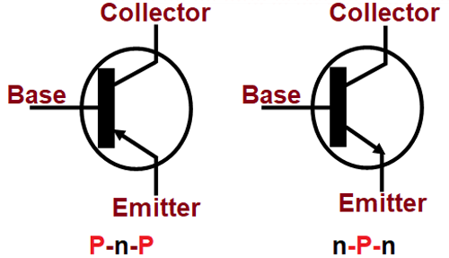
The three terminals shown in a typical BJT symbol are:
- Emitter (E) – where current exits
- Base (B) – control terminal
- Collector (C) – where current enters
The arrow on the emitter is the most important visual element. It indicates current direction and identifies the transistor type.
What the symbol conveys:
- Direction of conventional current
- Control relationship between terminals
- Type of charge carriers (indirectly)
- Switching or amplification role in the circuit
In short, the transistor symbol acts as a bridge between physical semiconductor behavior and practical circuit design.
How to Read a Transistor Symbol Step by Step?
Reading a transistor symbol becomes simple when you follow a structured approach. This avoids confusion, especially when working with complex schematics.
Step-by-step method:
- Identify the three terminals
- Look for base, collector, and emitter
- The base is usually the middle line
- Locate the arrow
- The arrow is always on the emitter
- It shows current direction
- Determine transistor type
- Arrow pointing out → NPN
- Arrow pointing in → PNP
- Check connections
- See how each terminal connects to other components
- This reveals the transistor’s role
- Understand function in context
- Is it switching?
- Is it amplifying?
- Is it part of a logic circuit?
This method works reliably across most circuit diagrams, from simple educational circuits to high-density industrial PCBs.
Does a Transistor Follow Ohm’s Law?
A transistor does not strictly follow Ohm’s law because it is not a simple resistive device. Ohm’s law applies to linear components like resistors, where voltage and current have a direct relationship.
However, parts of a transistor circuit may still obey Ohm’s law. For example:
- The resistors connected to the transistor follow Ohm’s law
- Biasing networks are often calculated using Ohm’s law
- Load resistors determine current levels
Inside the transistor itself, behavior is nonlinear. The relationship between voltage and current depends on semiconductor physics rather than a fixed resistance.
So in practice:
- Use Ohm’s law for surrounding components
- Use transistor equations or datasheets for device behavior
What are the Two Types of Transistors?
The two primary types of transistors used in electronics are:
- BJT (Bipolar Junction Transistor)
- FET (Field Effect Transistor)
Within BJT, there are two subtypes:
- NPN transistor
- PNP transistor
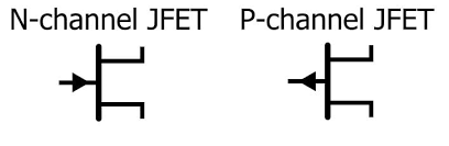
Within FET, common types include:
- MOSFET
- JFET
Each type serves different roles in circuit design.
Key differences:
- BJT uses current control
- FET uses voltage control
- FET typically offers higher input impedance
- BJT often provides stronger gain in analog circuits
In PCB assembly projects, the choice depends on performance targets such as speed, power consumption, and signal integrity.
How to Tell if a Transistor is NPN or PNP?
The easiest way to identify a transistor type is by looking at the arrow in the symbol.
- NPN transistor
- Arrow points outward
- Current flows out of the emitter
- PNP transistor
- Arrow points inward
- Current flows into the emitter
Another way is by analyzing circuit connections:
- NPN typically connects emitter to ground
- PNP often connects emitter to positive voltage
In real PCB troubleshooting, this visual identification saves time and prevents wiring mistakes.
NPN vs PNP Transistor Symbols: What Are the Key Differences?
Understanding the difference between NPN and PNP transistor symbols is essential for accurate circuit interpretation.
| Feature | NPN Transistor | PNP Transistor |
|---|---|---|
| Arrow Direction | Outward | Inward |
| Current Flow | Emitter to ground | From supply to emitter |
| Control Signal | Positive base voltage | Negative base voltage |
| Common Use | Switching, amplification | High-side switching |
| Popularity | More widely used | Less common |
This comparison highlights why NPN transistors are more frequently used in modern designs. They are easier to integrate with standard logic levels.
Which Transistor is Faster, NPN or PNP?
In most cases, NPN transistors are faster than PNP transistors.
This is due to the mobility of charge carriers:
- NPN uses electrons, which move faster
- PNP uses holes, which move slower
Because of this:
- NPN transistors switch faster
- They are preferred in high-speed circuits
- They are widely used in digital electronics
For applications like signal processing or fast switching, NPN devices are often the first choice.
What is a Transistor Used For?
Transistors are the backbone of modern electronics. They serve multiple roles across different types of circuits.
Common applications include:
- Signal amplification
- Electronic switching
- Voltage regulation
- Logic gate construction
- Power control
In PCB manufacturing, transistors are used in:
- Power supply circuits
- Communication modules
- Automotive electronics
- Industrial control systems
Their ability to control large currents with small signals makes them indispensable in both simple and complex designs.
How to Tell If a Transistor is Bad?
A faulty transistor can cause circuit failure or unstable performance. Identifying a bad transistor is a key diagnostic skill.
Common signs include:
- No switching action
- Overheating
- Unexpected voltage readings
- Signal distortion
Basic testing steps:
- Use a multimeter in diode mode
- Check base-emitter junction
- Check base-collector junction
- Compare readings with expected values
If the readings are inconsistent or show short circuits, the transistor may be damaged.
In production environments, more advanced testing methods like curve tracing or functional testing are used to ensure reliability.
FAQs
1. What is the meaning of a transistor symbol?
A transistor symbol shows how the device connects and how current flows. It simplifies complex semiconductor behavior into a clear diagram.
2. Why is the arrow important in a transistor symbol?
The arrow indicates current direction and helps identify whether the transistor is NPN or PNP.
3. Can a transistor work without a symbol in a diagram?
In practice, no. Without the symbol, it becomes difficult to interpret circuit function and connections.
4. Is the transistor symbol the same worldwide?
Yes, standard symbols are used globally to ensure consistency across designs and documentation.
5. Do all transistors have three terminals?
Most common transistors have three terminals, but some specialized devices may differ.
Conclusion
From identifying NPN and PNP types to understanding signal flow and functionality, mastering this symbol unlocks deeper insight into electronic systems. It also reduces design errors and speeds up development cycles.
If you are working on PCB design, assembly, or electronic product development, having a clear understanding of transistor symbols will directly improve your efficiency and accuracy.
For professional PCB fabrication and PCBA support, feel free to reach out to our engineering team at sales@bestpcbs.com.
You may also like


Tags: bjt transistor symbol, npn transistor symbol, transistor symbol, transistor symbol and function, transistor symbol meaning