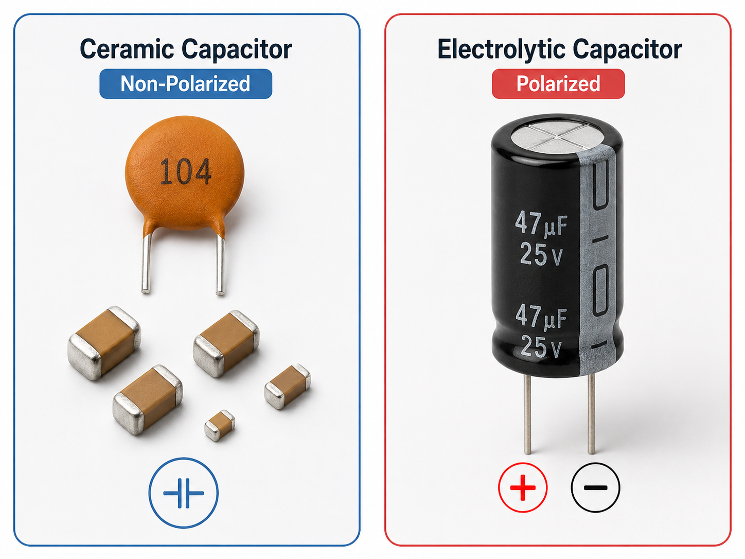
Do ceramic capacitors have polarity? In most cases, ceramic capacitors do not have polarity. A standard ceramic disc capacitor, multilayer ceramic capacitor, or ceramic SMD capacitor is a non polarized ceramic capacitor. It does not have a fixed positive or negative terminal, so it can usually be installed in either direction. This is different from aluminum electrolytic capacitors and tantalum capacitors, which normally require correct polarity during PCB assembly.
However, the answer should not stop at “yes” or “no.” In real PCB design and PCBA production, engineers still need to confirm the capacitor type, value, voltage rating, dielectric material, package size, and assembly data. A ceramic capacitor may not need polarity control, but it still needs correct selection and accurate placement. Wrong capacitance, wrong voltage rating, or wrong package can still affect circuit performance.
Does ceramic capacitor have polarity?
A standard ceramic capacitor does not have polarity. It has two terminals, but neither terminal is permanently positive or negative. In most circuits, either side can be connected to the higher voltage node or the lower voltage node, as long as the capacitor is used within its rated electrical conditions.
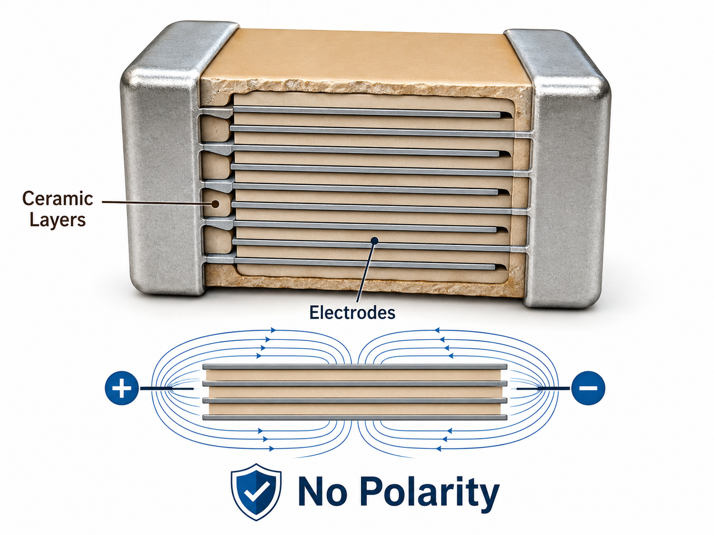
This applies to most ceramic disc capacitors and multilayer ceramic capacitors, often called MLCCs. These capacitors use ceramic material as the dielectric between conductive electrodes. The dielectric structure does not depend on a chemically formed positive or negative layer, so the part can work with voltage applied in either direction.
For ceramic SMD capacitor polarity, the rule is the same. Common SMD ceramic capacitors in packages such as 0402, 0603, 0805, 1206, and 1210 are normally non-polarized. During SMT assembly, they do not need to be placed according to a positive or negative terminal.
This feature is useful in PCB layout. Designers can place ceramic capacitors in the shortest and most effective path, especially near IC power pins. For decoupling and bypassing, close placement is often more important than visual orientation. A 100 nF ceramic capacitor near a microcontroller, power management IC, memory chip, or RF module can usually face either direction without changing its basic function.
Still, “no polarity” does not mean the capacitor can be used without limits. The voltage rating must fit the circuit. The capacitance tolerance must match the design target. The dielectric class, such as C0G/NP0, X7R, X5R, or Y5V, should be selected according to stability, temperature range, DC bias behavior, and application requirements. The PCB footprint must also match the package.
So, does ceramic capacitor have polarity? For normal ceramic disc capacitors and ceramic SMD capacitors, the answer is no. They are non-polarized components. The main engineering task is not to identify positive and negative terminals, but to confirm that the capacitor specification is suitable for the circuit.
How to tell if a capacitor has polarity?
You can tell whether a capacitor has polarity by checking its body marking, package style, schematic symbol, BOM description, and datasheet. Polarized capacitors usually have a clear indication for the positive or negative terminal. Non-polarized capacitors usually do not have polarity marks.
Aluminum electrolytic capacitors are the most common polarized capacitors. A through-hole aluminum electrolytic capacitor often has a stripe on the body to mark the negative side. Before trimming, the longer lead usually indicates the positive terminal. SMD aluminum electrolytic capacitors may use a printed mark, a colored region, or a top-side polarity sign to show orientation.
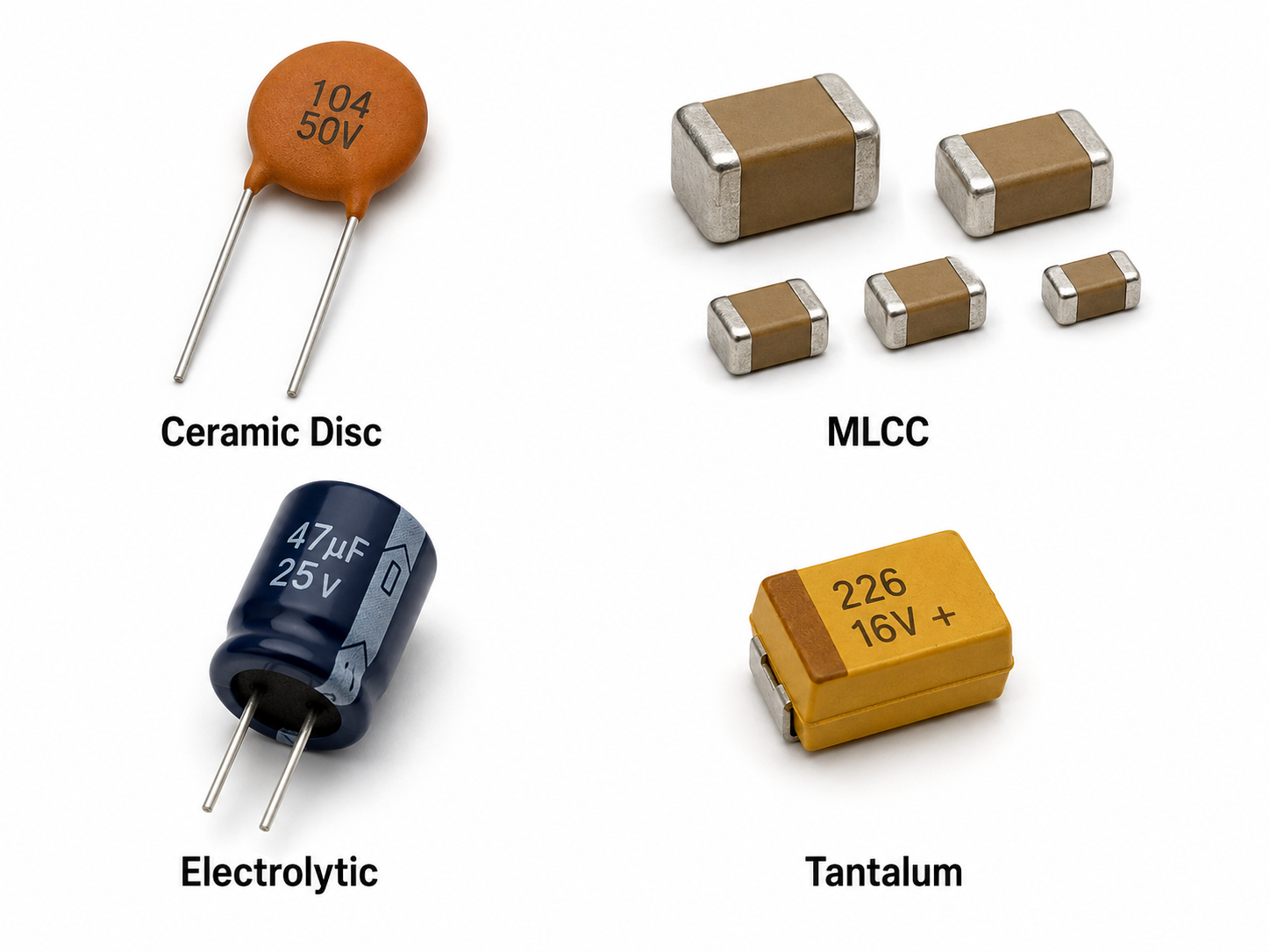
Tantalum capacitors are also polarized, but their marking style is different from many aluminum electrolytic capacitors. A tantalum capacitor often marks the positive side. This difference is important because assuming that all stripes indicate the same terminal can cause assembly errors.
Ceramic capacitors are different. A ceramic disc capacitor usually has two leads with no positive or negative mark. A ceramic SMD capacitor usually looks like a small rectangular chip with metal terminations on both ends. Most small MLCCs have no printed text or polarity sign. Their value and specification are confirmed through the reel label, BOM, part number, and datasheet.
| Capacitor Type | Polarity | Common Marking | Typical Use |
|---|---|---|---|
| Ceramic disc capacitor | No | Value code, usually no polarity mark | Filtering, coupling, general circuits |
| Ceramic SMD capacitor / MLCC | No | Usually no body marking on small sizes | Decoupling, bypassing, RF, digital circuits |
| Aluminum electrolytic capacitor | Yes | Negative stripe or PCB positive mark | Bulk filtering, power smoothing |
| Tantalum capacitor | Yes | Often positive-side marking | Compact power filtering |
| Film capacitor | Usually no | Value and voltage marking | AC coupling, audio, EMI circuits |
| Supercapacitor | Usually yes | Positive and negative marks | Backup power, energy storage |
The safest method is to check the BOM and manufacturer part number. For example, a BOM line that says “CAP CER 100nF 50V X7R 0603” describes a ceramic SMD capacitor and normally has no polarity. A BOM line that says “CAP ALUM 100µF 25V” describes an aluminum electrolytic capacitor, which normally requires polarity control.
The schematic can also help. Non-polarized capacitors are often shown as two equal parallel plates. Polarized capacitors may include a plus sign or a curved plate. PCB silkscreen may also show polarity marks for polarized capacitors. Since library symbols and footprint styles can vary, the datasheet should be treated as the final reference when there is any doubt.
In PCBA production, EBest Circuit recommends using complete BOM data, including capacitance, voltage rating, tolerance, dielectric type, package, manufacturer part number, and polarity notes when needed.
How to determine polarity of ceramic capacitor?
For a normal ceramic capacitor, there is no polarity to determine. The correct question is whether the component is truly a ceramic capacitor. Once the part is confirmed as a standard two-terminal ceramic capacitor, it can usually be installed in either direction.
Ceramic capacitor polarity identification should begin with the BOM. Descriptions such as “ceramic,” “MLCC,” “multilayer ceramic,” “C0G,” “NP0,” “X7R,” “X5R,” and “Y5V” usually indicate a non polarized ceramic capacitor. Descriptions such as “aluminum electrolytic,” “tantalum,” “polymer,” or “supercapacitor” suggest that polarity may apply.
For through-hole ceramic disc capacitors, printed codes such as 104, 103, 471, or 222 usually refer to capacitance value. For example, 104 means 100,000 pF, which equals 0.1 µF. These printed numbers are not polarity marks. If the capacitor is a standard ceramic disc type, either lead can normally go into either pad.
For ceramic SMD capacitors, there is often no printing on the component body. Small MLCCs are identified through packaging labels, reel information, purchase records, and assembly documentation. During manufacturing, the pick-and-place file may define a rotation angle, but this does not mean the capacitor has polarity. It simply tells the machine how to pick and place the part consistently.
A practical verification process can include the following steps:
- Check the BOM description and manufacturer part number.
- Confirm the dielectric type and package from the datasheet.
- Look for any polarity mark on the component body or PCB silkscreen.
- Compare the schematic symbol with the PCB footprint.
- Ask for engineering confirmation if the part description is unclear.
This process is useful because many SMD parts look similar after mounting. A ceramic capacitor, resistor, ferrite bead, small inductor, and certain protection components may have similar sizes. Reference designators help distinguish them. Capacitors are usually marked as C, resistors as R, inductors as L, and ferrite beads as FB or sometimes L depending on the company’s design standard.
What are the disadvantages of ceramic capacitors?
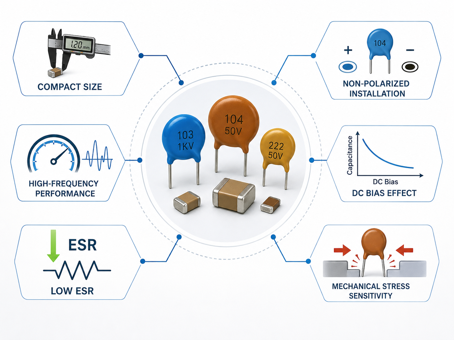
Ceramic capacitors have many practical advantages, including compact size, low ESR, good high-frequency behavior, and non-polarized installation. They are widely used for decoupling, bypassing, filtering, and signal coupling. At the same time, they have limitations that should be considered during design.
One important factor is DC bias. Many high-capacitance MLCCs lose part of their effective capacitance when DC voltage is applied. This effect is stronger in smaller package sizes and higher capacitance values.
Temperature behavior is another factor. C0G/NP0 ceramic capacitors are very stable across temperature and are often used in RF, timing, and precision circuits. X7R and X5R capacitors provide higher capacitance in smaller packages, but their capacitance changes more with temperature and voltage. This is not a defect. It simply means the dielectric type must match the circuit requirement.
Aging also matters for some ceramic dielectrics. Class 2 ceramic capacitors, such as X7R and X5R, can show capacitance reduction over time. For most decoupling applications, this is manageable when the design includes proper margin. For precision analog or timing circuits, a more stable dielectric such as C0G/NP0 is often preferred.
Mechanical stress should also be considered. MLCCs are made from hard ceramic material. Board bending, rough depaneling, connector insertion force, screw stress, or thermal shock may create cracks. Larger MLCC packages are more sensitive to board flex than smaller ones. In automotive, industrial, and high-reliability applications, soft termination MLCCs or improved layout placement may be used to reduce stress risk.
Ceramic capacitors may also produce acoustic noise in some power circuits. Under certain ripple conditions, MLCCs can vibrate due to piezoelectric behavior. This can create audible sound in products such as adapters, LED drivers, or compact power modules. Layout changes, package selection, voltage derating, or using a different capacitor type can help manage this issue.
| Design Factor | What It Means | Engineering Response |
|---|---|---|
| DC bias | Effective capacitance may drop under working voltage | Check manufacturer DC bias curves and use voltage margin |
| Temperature coefficient | Capacitance changes with dielectric type | Use C0G/NP0 for high stability; use X7R/X5R for compact capacitance |
| Aging | Some dielectrics lose capacitance over time | Add design margin for sensitive circuits |
| Mechanical stress | Ceramic body can crack under board flex | Avoid high-stress areas; consider soft termination parts |
| Acoustic noise | MLCCs may vibrate in some power circuits | Adjust layout, package, voltage rating, or capacitor type |
| Limited bulk energy storage | Very large capacitance may need other technologies | Combine ceramic with electrolytic or polymer capacitors when required |
The right approach is to use ceramic capacitors where their characteristics fit the circuit. They are often suitable near IC power pins because they respond well at high frequencies. Electrolytic or polymer capacitors may be better for larger bulk capacitance. Film capacitors may be selected for certain AC, audio, or precision circuits.
For PCB and PCBA projects, EBest Circuit (Best Technology) reviews capacitor selection together with PCB layout, stack-up, soldering process, and product environment.
How Can You Tell If a Capacitor Is Ceramic?
You can often recognize a ceramic capacitor by its body shape, package, color, marking style, circuit position, and BOM description. Visual inspection helps, but the BOM and datasheet provide the most reliable confirmation.
A through-hole ceramic disc capacitor is usually a flat disc with two radial leads. The body may be orange, yellow, blue, brown, or light tan. It often has a printed capacitance code, such as 104, 103, 472, or 221. These codes identify value, not polarity. Standard ceramic disc capacitor polarity is not marked because the component is normally non-polarized.
A ceramic SMD capacitor is usually a small rectangular chip with metal end terminations. Common package sizes include 0201, 0402, 0603, 0805, 1206, and 1210. The body is often beige, cream, gray, or light brown. Many small MLCCs have no printed value because the surface area is too small.
Circuit location can also provide clues. Ceramic capacitors are often placed near IC power pins for decoupling. They may appear in groups around microcontrollers, FPGAs, memory ICs, RF chips, sensors, and power management ICs. In these locations, they help reduce high-frequency noise and stabilize local power delivery.
Common signs that a capacitor is ceramic include:
- The BOM includes “ceramic,” “MLCC,” “C0G,” “NP0,” “X7R,” or “X5R.”
- The part is a small rectangular SMD chip with no polarity mark.
- The through-hole part has a disc-shaped body.
- The schematic uses a non-polar capacitor symbol.
- The component is placed near an IC power pin or in a filter network.
However, visual inspection alone can be misleading. Some resistors, ferrite beads, inductors, and small protection devices may look similar to ceramic capacitors. The reference designator gives an important clue. Capacitors are usually labeled C on the PCB and schematic. Resistors are labeled R, inductors are labeled L, and ferrite beads may be labeled FB.
Does polarity matter on a capacitor?
Polarity matters on some capacitors, but not on all capacitors. Whether polarity matters depends on the capacitor’s internal construction. A polarized capacitor must be installed in the correct direction. A non-polarized capacitor can be installed in either direction.
For ceramic capacitors, polarity usually does not matter. Most ceramic capacitors are non-polarized, so they can be used in DC circuits, AC circuits, coupling paths, decoupling networks, and filter circuits without positive and negative orientation. This is one reason ceramic capacitors are so common in PCB assembly.
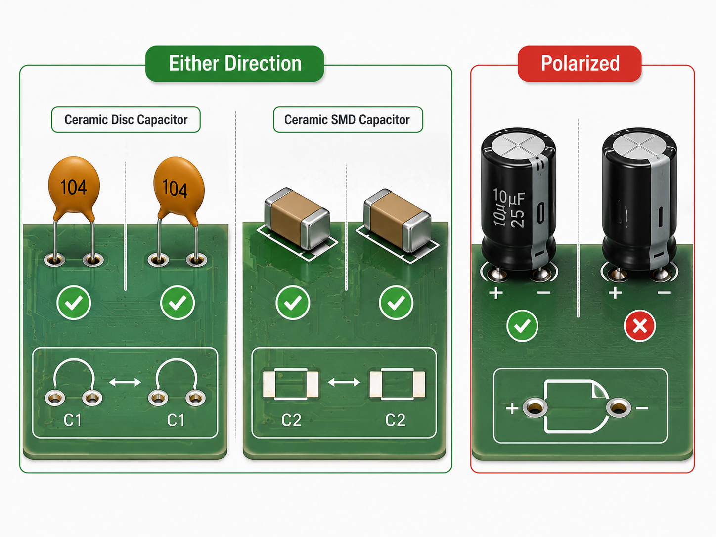
For aluminum electrolytic capacitors, tantalum capacitors, polymer capacitors, and supercapacitors, polarity normally matters. These components have a defined positive and negative terminal. If they are installed incorrectly, the circuit may not work as intended, and the capacitor may be damaged. PCB footprints for polarized capacitors usually include orientation marks to guide assembly.
| Question | Ceramic Capacitor | Aluminum Electrolytic Capacitor | Tantalum Capacitor |
|---|---|---|---|
| Does polarity matter? | Usually no | Yes | Yes |
| Can it be installed either way? | Usually yes | No | No |
| Common polarity mark | Usually none | Negative stripe or PCB plus mark | Often positive-side mark |
| Common use | Decoupling, filtering, RF, coupling | Bulk filtering, power smoothing | Compact power filtering |
| Main assembly check | Value, package, voltage, dielectric | Value, package, voltage, polarity | Value, package, voltage, polarity |
In short, polarity does not usually matter for ceramic capacitors, but it matters for many electrolytic, tantalum, polymer, and supercapacitor parts.
Why do ceramic capacitors have no polarity?
Ceramic capacitors have no polarity because of their internal dielectric and electrode structure. They use ceramic material as the insulating dielectric between conductive electrodes. This structure can store charge with voltage applied in either direction, as long as the capacitor remains within its rated voltage and operating range.
This is different from aluminum electrolytic capacitors. An electrolytic capacitor uses an oxide layer formed on a specific electrode. That structure is designed to operate with a defined positive and negative direction. Ceramic capacitors do not rely on that same electrochemical structure, so they do not need a fixed terminal orientation.
A multilayer ceramic capacitor contains many thin ceramic layers and electrode layers stacked together. Alternate electrode layers connect to opposite end terminations. When voltage is applied, electric fields form across the ceramic dielectric layers. Because the two-terminal MLCC structure is generally symmetrical for normal use, either terminal can be connected to the higher voltage side.
Even though ceramic capacitors have no polarity, voltage rating still matters. A non-polar component can be connected in either direction, but it should not be used above its specified voltage. Engineers often apply voltage derating, especially in industrial, automotive, medical, and power electronics applications. This improves design margin and helps manage DC bias effects in MLCCs.
Which capacitor has no polarity?
Ceramic capacitors are the most common non-polarized capacitors used in PCB assembly, but they are not the only ones. Film capacitors, mica capacitors, many safety capacitors, and some special non-polar electrolytic capacitors also have no fixed polarity.
A non-polarized capacitor is useful when the circuit voltage may reverse direction or when the signal is AC. These capacitors are common in coupling circuits, filters, RF networks, timing circuits, audio paths, EMI suppression, and general decoupling.
| Non-Polar Capacitor Type | Polarity | Main Strength | Common Application |
|---|---|---|---|
| Ceramic capacitor | No | Small size, high-frequency performance | Decoupling, bypass, RF, filtering |
| Film capacitor | No | Stability and AC performance | Audio, power, EMI suppression |
| Mica capacitor | No | High stability | RF and precision circuits |
| Safety capacitor | Usually no | Certified safety use | Mains EMI filtering |
| Non-polar electrolytic capacitor | No | Higher capacitance for AC use | Audio crossover and special AC circuits |
The choice depends on circuit requirements. A 100 nF ceramic capacitor is commonly used for IC decoupling. A film capacitor may be selected for AC coupling or EMI applications. A safety capacitor is required in line-related positions. A non-polar electrolytic capacitor may be used where higher capacitance is needed in an AC path.
For most PCB projects, ceramic capacitors are the first non-polar option engineers consider because they are compact, available, and compatible with SMT production. Still, the correct capacitor type should always be selected based on voltage, capacitance, frequency, tolerance, temperature, and reliability requirements.
Can a Ceramic Capacitor Be Installed in Either Direction?
Yes, a standard ceramic capacitor can be installed in either direction. This applies to most ceramic disc capacitors and ceramic SMD capacitors. Since they are non-polarized, rotating the component 180 degrees does not change its normal electrical function.
This feature simplifies both manual soldering and automated SMT assembly. A ceramic disc capacitor can usually be inserted into a through-hole footprint either way. A ceramic SMD capacitor can usually be placed without positive or negative orientation. The placement file may still define rotation for machine control, but that rotation is not usually related to capacitor polarity.
In repair work, this also makes replacement easier. If a technician replaces a standard MLCC or ceramic disc capacitor, the key points are value, voltage rating, package size, dielectric type, and solder quality. Direction is normally not the deciding factor.
However, the component must first be identified correctly. A part that looks similar may not be a ceramic capacitor. Tantalum capacitors, diodes, LEDs, TVS diodes, ferrite beads, and other small SMD components may require different handling. The safest approach is to check the reference designator, BOM, schematic, and datasheet before replacing or assembling parts.
Some special ceramic-based components may also have defined pin arrangements. Capacitor arrays, EMI filters, feedthrough capacitors, and integrated passive components should be checked through their datasheets. They may use ceramic materials, but they are not the same as a standard two-terminal MLCC.
In summary, most ceramic capacitors have no polarity and can be installed in either direction. Ceramic capacitor polarity identification mainly means confirming that the component is a standard ceramic capacitor and verifying its capacitance, voltage rating, dielectric, package, and application fit.
For PCB fabrication, SMT assembly, BOM review, component sourcing, and turnkey PCBA support, EBest Circuit (Best Technology) can help review these details before production. If you have a PCB or PCBA project that needs engineering support or quotation, contact sales@bestpcbs.com