A 2 pin PCB connector is a simple connection part used to link a PCB with wires, power input, batteries, sensors, LEDs, motors or external devices. Although it has only two positions, the wrong connector can cause loose contact, reverse polarity, overheating, solder joint cracking and unstable field performance.
For PCB assembly, the connector must match current rating, pitch, wire gauge, mounting method, PCB layout, soldering process and testing requirements. Therefore, selection should start from real electrical load and production conditions, not only size or price. This guide explains how to choose a reliable 2 pin connector for PCB projects and avoid common assembly risks.
What Is a 2 Pin PCB Connector?
A 2 pin PCB connector is a two-position electrical connector mounted on a PCB to create a connection between the circuit board and an external wire, cable, module or another PCB. It usually includes two metal contacts, an insulating housing and a PCB mounting structure.
In real projects, this part may be described as a 2 pin connector PCB, PCB connector 2 pin, 2 pin connector for PCB, two-pin PCB connector or two-position PCB connector. These terms usually refer to the same purpose: creating a compact and removable two-line electrical connection on a PCB.
Key takeaway: A 2 pin PCB connector is simple in structure, but its footprint, mating plug, current rating and soldering process must be confirmed before assembly.
What Is a 2 Pin PCB Connector Used For?
A 2 pin PCB connector is mainly used for two-line electrical connections. It can carry positive and negative power, simple signal input, sensor output, switch control or low-voltage communication lines. In addition, it helps make wiring, testing, repair and product assembly easier.
Common uses include:
- DC power input: Battery packs, adapters, chargers and control boards.
- LED wiring: LED strips, lighting modules and indicator boards.
- Motor and fan control: Two-wire motors, fans and actuators.
- Sensor connection: Temperature sensors, switches, alarms and small modules.
- Testing access: Temporary power or signal connection during PCB testing.
- Cable harness assembly: Plug-in wiring for finished PCBA products.
For power circuits, a 2 pin PCB power connector should have enough current margin. For signal circuits, the focus should be stable contact, clear polarity and secure mating.
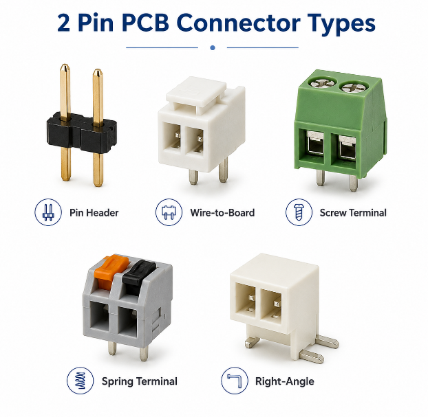
What Are the Common Types of 2 Pin PCB Connectors?
Common 2 pin PCB connector types are divided by connection style, mounting method and wiring method. Each type fits different product structures, cable handling methods and assembly conditions.
| Type | Use | Feature |
|---|---|---|
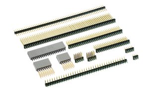
| Pin header | Signal, jumper, test port | Low cost and simple structure |
| Wire-to-board connector | Cable harness to PCB | Compact and secure mating |
| Screw terminal block | Field wiring and power input | Easy manual wire locking |
| Spring terminal block | Tool-free wiring | Fast wire insertion |
| Board-to-board connector | PCB module connection | Compact board stacking |
| Right-angle connector | Side cable entry | Saves product height |
| Vertical connector | Top cable entry | Easy plug-in access |
| PCB edge connector | Board edge interface | Uses PCB edge contact |
A 2 pin PCB connector header is usually used for low-current signals, jumpers or test points. A 2 pin PCB wire connector is better for cable harness assembly. Meanwhile, a screw or spring terminal is more suitable when users connect bare wires during installation.
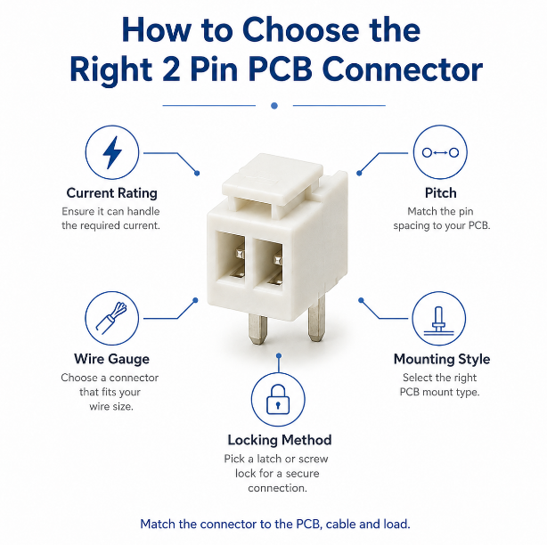
How to Choose the Right 2 Pin PCB Connector?
Choose a 2 pin PCB connector by checking electrical requirements first, then mechanical fit, mounting style, cable condition and production stability. This sequence helps avoid wrong footprint, poor mating, weak solder joints and sourcing problems.
- Confirm current and voltage: The connector should have safe margin above real working load.
- Check pitch and footprint: Pin spacing, hole size and pad shape must match the PCB design.
- Match wire gauge: The terminal must support the planned cable size and strip length.
- Choose mounting style: Through-hole gives stronger support; SMT saves PCB space.
- Review mating direction: Vertical, right-angle and side-entry designs affect enclosure clearance.
- Add polarity protection: Keyed housing, silkscreen marks and asymmetric layout reduce reverse insertion.
- Check connector supply: Common connector series reduce shortage risk in mass production.
- Confirm soldering method: Housing material must match reflow, wave soldering or hand soldering.
For a custom 2 pin connector PCB mount project, selection should balance electrical safety, mechanical strength, assembly yield and long-term availability.
What Pitch Options Are Common for 2 Pin PCB Connectors?
Pitch is the center-to-center distance between the two connector pins. For a 2 pin PCB connector, common pitch options include 1.25 mm, 2.0 mm, 2.54 mm, 3.5 mm, 3.81 mm, 5.0 mm and 5.08 mm.
| Pitch | Typical Use | Design Note |
|---|---|---|
| 1.25 mm | Miniature electronics | Small wire and low current |
| 2.0 mm | Battery and compact modules | Space-saving connection |
| 2.54 mm | Headers and test ports | Common PCB pitch |
| 3.5 mm | Control boards | Balanced size and wiring |
| 3.81 mm | Industrial modules | Common pluggable terminal pitch |
| 5.0 mm | Power input | Better spacing and wiring access |
| 5.08 mm | Industrial power wiring | Common terminal block pitch |
Smaller pitch saves board space, but it usually limits wire size, current rating and manual handling. Larger pitch improves insulation distance, wire insertion and assembly tolerance. Therefore, compact products may use JST-style 2 pin PCB connector options, while industrial boards often use larger terminal blocks.
How Much Current Can a 2 Pin PCB Power Connector Carry?
A 2 pin PCB power connector can carry less than 1A or more than 20A, depending on contact size, pitch, wire gauge, plating, housing material and PCB copper design. However, the datasheet rating should not be treated as the only decision point.
Connector ratings alone are not enough. PCB copper thickness, trace width, pad size, solder joint quality and ambient temperature also determine safe current capacity. For example, a connector may be rated for high current, but the PCB may still overheat if the copper path is too narrow.
For power input, battery charging, motor control and LED driver boards, choose a 2 pin PCB connector with current margin. In addition, perform real load testing before mass production. A safe design usually avoids running the connector at its absolute maximum rating.
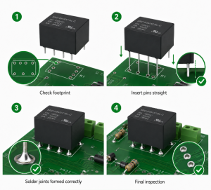
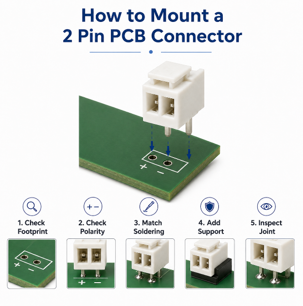
How Should a 2 Pin PCB Connector Be Mounted on a PCB?
A 2 pin PCB connector should be mounted according to its footprint, polarity, soldering method and mechanical load. Correct mounting improves solder quality, connector strength and long-term reliability, especially when the connector handles cable pulling or repeated plug-in use.
Step 1: Confirm the connector footprint.
Before assembly, check pin spacing, pad size, hole diameter, orientation and connector outline against the datasheet. This prevents wrong pitch, wrong pad design and connector tilt during production.
Step 2: Check polarity and assembly direction.
The PCB should clearly show “+”, “-”, pin 1 marks or connector outline. For a 2 pin PCB power connector, polarity control is critical because reverse wiring may damage the circuit immediately.
Step 3: Match the soldering process.
SMT connectors are assembled with solder paste printing, placement and reflow soldering. Through-hole connectors are inserted into plated holes and soldered by wave soldering, selective soldering or manual soldering. The housing material must tolerate the chosen soldering temperature.
Step 4: Add mechanical support when needed.
For a 2 pin PCB mount connector exposed to cable force, use larger pads, anchor pins, mounting posts, strain relief, enclosure support or thicker copper around connector pads. This reduces pad lifting and solder joint cracking.
Step 5: Inspect the mounted connector.
After soldering, check alignment, solder fillet, housing damage, pin exposure and connector height. If the connector must mate with a cable harness, perform a plug-in fit check before final approval.
Key takeaway: Connector mounting is not only a soldering task. It must control footprint accuracy, polarity, solder quality and mechanical stress together.
How Does PCB Layout Affect 2 Pin PCB Connector Reliability?
PCB layout directly affects 2 pin PCB connector reliability because the connector transfers current, heat and mechanical force into the PCB. A poor layout can cause voltage drop, pad lifting, solder cracks, overheating or wrong cable insertion.
Important layout rules include:
- Use wide traces for power: The copper path should match real load current.
- Increase pad copper area: Larger copper improves heat spreading and solder strength.
- Mark polarity clearly: Use “+”, “-”, pin 1 marks and connector outlines.
- Avoid weak board edges: Heavy connectors should not rely only on thin PCB edge support.
- Check cable direction: Leave space for insertion, removal and cable bending.
- Separate noisy paths: Keep sensitive signals away from high-current connector pads.
- Follow IPC-2221 design logic: Trace width, clearance and spacing should match voltage and current needs.
For a 2 pin PCB board connector, layout review should include connector datasheet, mating plug, cable route, enclosure space and assembly process. Good layout reduces both electrical failure and mechanical damage.
What Common Problems Happen During 2 Pin PCB Connector Assembly?
Common 2 pin PCB connector assembly problems include wrong direction, wrong pitch, poor solder wetting, tilted placement, melted housing, insufficient solder, reversed polarity and mismatched mating plugs. These issues often happen when the connector is selected late or the footprint is copied without datasheet review.
Typical risks include:
- Wrong footprint: Pin spacing, pad size or hole diameter does not match the actual connector.
- Connector tilt: The part moves during reflow, wave soldering or manual soldering.
- Weak solder joints: Pad size, solder amount or wetting is not enough.
- Plastic deformation: Soldering temperature exceeds housing tolerance.
- Reverse installation: PCB silkscreen and assembly drawing are unclear.
- Loose cable fit: Plug, crimp terminal or wire gauge does not match.
- Overheating: Current exceeds connector, wire or PCB copper capacity.
- Poor retention: No latch, screw, anchor or strain relief is used.
In mass production, many failures can be prevented by DFM review, incoming connector inspection, first-article assembly approval and functional testing. Therefore, connector checking should be completed before PCB assembly starts, not after finished boards fail testing.
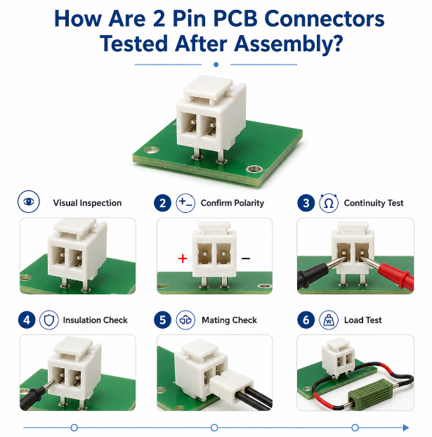
How Are 2 Pin PCB Connectors Tested After Assembly?
After assembly, a 2 pin PCB connector should be tested by inspection, electrical verification and functional checks. For power boards or products used in vibration, outdoor or industrial environments, pull force and load testing should also be considered.
Step 1: Perform visual inspection.
Check connector position, tilt, housing damage, pin alignment and solder fillet shape. For SMT connectors, AOI can help detect missing solder, bridging or poor wetting. For through-hole connectors, inspect both solder side and component side when possible.
Step 2: Confirm polarity.
Check whether the positive and negative pins match the schematic, PCB silkscreen and assembly drawing. This step is especially important for battery input, LED modules, DC power boards and motor control PCBA.
Step 3: Run continuity testing.
Use electrical testing to confirm that each connector pin is correctly connected to the target circuit. This helps detect open circuits, wrong routing, poor solder joints and broken traces.
Step 4: Check insulation between pins.
For power or higher-voltage applications, verify that the two pins are not shorted and that the spacing is suitable for the working voltage. If required, insulation resistance testing can be added.
Step 5: Verify mating and retention.
Insert the matching plug or cable harness to confirm fit, latch engagement, insertion direction and removal force. For a 2 pin PCB wire connector, the crimp terminal and wire gauge should also be checked.
Step 6: Run functional and load testing.
Power the board under real operating conditions and check voltage, current and temperature rise. For a 2 pin PCB power connector, load testing is more useful than visual inspection alone because overheating may only appear during operation.
IPC-A-610 and J-STD-001 workmanship expectations are often used to guide solder joint inspection. In addition, RoHS material control and UL-rated connector materials may be checked when the customer project requires them. Testing should always follow approved drawings, BOM notes and customer quality plans.
Key takeaway: Testing should confirm not only whether the connector is soldered correctly, but also whether it can carry real current, mate securely and remain stable during product use.
How Much Does 2 Pin PCB Connector Assembly Cost?
The cost of 2 pin PCB connector assembly depends on connector type, brand, pitch, mounting method, soldering process, inspection level, sourcing stability and order quantity. A simple header costs less, while a locking wire-to-board connector, pluggable terminal block or high-current terminal block costs more.
| Factor | Cost Impact |
|---|---|
| Connector type | Terminal blocks and locking types cost more |
| Pitch | Fine pitch may increase assembly difficulty |
| Mounting method | Through-hole may add soldering steps |
| Current rating | Higher rating increases material cost |
| Brand | Original branded parts may cost more |
| Inspection | More tests increase labor time |
| Quantity | Bulk orders reduce unit price |
| Lead time | Shortage parts increase sourcing risk |
| Cable matching | Harness verification adds labor cost |
The cheapest connector is not always the lowest-cost choice. A stable 2 pin PCB connector with good assembly yield can reduce rework, testing failure and after-sales risk. Therefore, buyers should compare total project cost instead of only unit price.
How Can EBest Support PCB Assembly with 2 Pin PCB Connectors?
EBest supports PCB assembly projects using 2 pin PCB connectors by reviewing connector selection, PCB footprint, polarity marking, soldering process, cable mating and final testing before production. This helps reduce wrong part selection, assembly rework and field connection failures.
EBest can support:
- PCB fabrication: FR4 PCB, aluminum PCB, HDI PCB, rigid-flex PCB and custom PCB structures.
- Component sourcing: 2 pin PCB connector sourcing, alternative review and BOM matching.
- SMT and through-hole assembly: Suitable soldering process for different connector types.
- Cable and mating check: Plug, crimp terminal and connector fit verification.
- Testing support: Continuity, polarity, functional and load testing.
- Quality control: IPC-based workmanship inspection and project-specific test plans.
- Global delivery: China source factory production with overseas shipment.
EBest is a China PCB and PCBA source factory, not an overseas warehouse or local branch. The value is direct manufacturing, custom assembly, controlled quality, flexible OEM/ODM support and global supply.
FAQs About 2 Pin PCB Connectors
Q1: Can a 2 pin PCB connector be used with battery packs?
A1: Yes. A 2 pin PCB connector is commonly used for battery positive and negative lines. However, battery circuits should use keyed housing, clear polarity marks and enough current margin. For rechargeable products, the connector, wire gauge and PCB copper path should also be checked under real charging and discharging load.
Q2: What is the difference between male and female 2 pin PCB connectors?
A2: A male connector usually has exposed pins, while a female connector uses receptacle contacts. In many cable assemblies, the PCB side may be male and the cable side may be female. The final choice depends on safety, mating direction and product structure. For power input, exposed live pins should be avoided when possible.
Q3: Is a locking 2 pin PCB connector better than a friction-fit type?
A3: A locking type is better when the cable may face vibration, movement or repeated handling. A friction-fit connector is simpler and often cheaper, but it may loosen more easily. For motors, fans, industrial modules and mobile devices, positive locking improves connection reliability and reduces field failure risk.
Q4: Can I use a 2 pin PCB connector for AC power?
A4: Yes, but only if the connector has the correct voltage rating, current rating, insulation distance and flame-retardant material. Many small two-position connectors are only suitable for low-voltage DC. For AC input, PCB creepage, clearance and safety requirements must be checked carefully before production approval.
Q5: Why does a 2 pin PCB connector become hot?
A5: Heat is usually caused by excessive current, poor mating, weak crimping, thin PCB copper, small pad area or oxidized contacts. The full current path should be reviewed, not only the connector datasheet. Check wire gauge, terminal contact, solder joint, trace width and temperature rise under real load.
Q6: What is a pluggable 2 pin PCB connector?
A6: A pluggable type allows the cable or terminal plug to be removed from the PCB header. It is common in industrial controls, power modules and maintenance-friendly devices. This design makes wiring easier during installation and service. However, the mating plug, pitch and locking method must match exactly.
Q7: Can a 2 pin PCB connector be waterproof?
A7: A normal PCB connector is not waterproof by default. Waterproof performance requires sealed housing, gasket, molded cable or protected enclosure design. For outdoor lighting, marine electronics or humid environments, check IP rating, connector sealing, conformal coating and enclosure protection together instead of relying on the connector alone.
Q8: What wire gauge should match a 2 pin PCB wire connector?
A8: The wire gauge must match the connector terminal range. If the wire is too small, clamping may be loose. If it is too large, the terminal may deform or fail to insert. Always confirm AWG range, strip length and crimp terminal specification before cable harness assembly.
Q9: Can I replace a screw terminal with a JST 2 pin PCB connector?
A9: Yes, but only when current, voltage, wire gauge and installation conditions are suitable. A screw terminal is better for field wiring and larger wires. A JST-style connector is better for compact products and controlled cable harness assembly. For high current, check temperature rise and retention force first.
Q10: What causes a 2 pin PCB connector to fall off the board?
A10: Common causes include weak SMT pad design, cable pulling, insufficient solder, wrong footprint, poor wetting and no mechanical support. For connectors exposed to stress, use through-hole pins, anchor tabs, support posts or strain relief. The PCB design should consider real cable force during use.
Q11: Is a 2 pin PCB edge connector the same as a normal header?
A11: No. A 2 pin PCB edge connector uses the PCB edge or plated contact area as part of the connection interface. A normal header is a separate component soldered to pads or holes. Edge connectors save height, but they require accurate board edge design and compatible mating slots.
Q12: What documents should buyers provide for connector assembly quotation?
A12: Buyers should provide Gerber files, BOM, connector part number, datasheet, assembly drawing, current requirement, mating plug details and order quantity. If the exact connector is not confirmed, provide pitch, mounting style, wire gauge and target current. These details help prevent wrong footprint and wrong sourcing.
Q13: Can EBest source alternative 2 pin PCB connectors?
A13: Yes. EBest can review alternatives based on pitch, footprint, current rating, height, mating plug, availability and cost. Before replacement, the alternative connector should be checked against PCB layout and cable harness. For mass production, sample approval and functional testing should be completed before batch use.
Q14: How can buyers reduce connector shortage risk?
A14: Buyers can reduce shortage risk by selecting common connector series, approving second sources early and avoiding rare parts with long lead times. For repeat orders, keeping the same connector family across related products can simplify sourcing. Before PCB assembly starts, confirm stock, lead time and approved alternatives.
Q15: What sample checks are recommended before mass production?
A15: Before mass production, check connector fit, mating plug insertion, polarity, solder joint quality, cable pull strength, enclosure clearance and functional performance. For a 2 pin PCB power connector, run a real load test and check temperature rise. Sample approval should confirm both electrical and mechanical reliability.
Conclusion
A reliable 2 pin PCB connector should be selected by current rating, pitch, wire gauge, mounting style, material, PCB layout, soldering process and final testing requirements. For low-current signal use, stable mating and clear polarity are important. For battery input, LED drivers, motor control and industrial wiring, current margin, copper design and mechanical support are more critical.
For procurement, do not choose a connector only by appearance or unit price. A qualified PCB assembly supplier should review the connector, footprint, mating cable, assembly process and test plan together before production. EBest Circuit is a China source PCB and PCBA manufacturer supporting custom connector assembly, OEM/ODM projects, bulk production and global delivery. Send your Gerber files, BOM and connector requirements to sales@bestpcbs.com for a fast quotation.