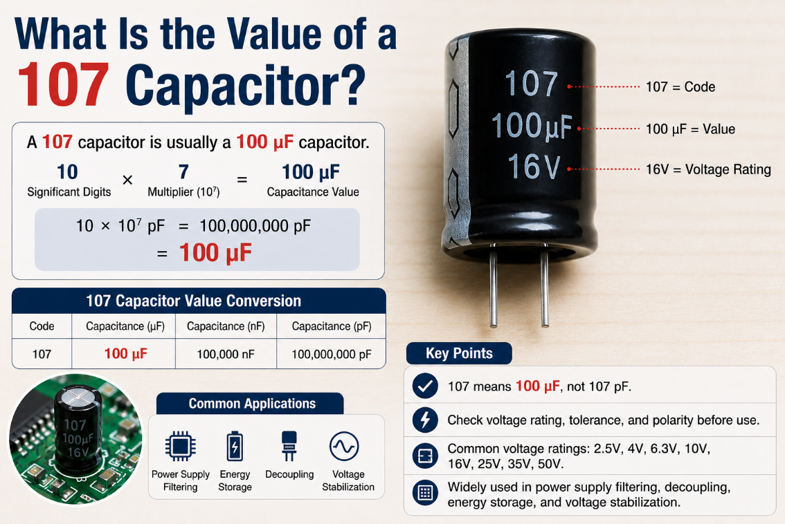
A 107 capacitor is usually a 100 uF capacitor when the marking follows the standard three-digit capacitor code. The first two digits are “10,” and the third digit “7” means seven zeros in pF, so the value is 10 × 10⁷ pF = 100,000,000 pF = 100 uF.
However, the marking alone does not confirm voltage, tolerance, dielectric material, polarity or package size. This component can be tantalum, aluminum electrolytic, ceramic, polymer or SMD. For safe replacement, engineers and buyers should check capacitance, voltage, polarity, ESR, temperature rating, package size and circuit function before placing an order.
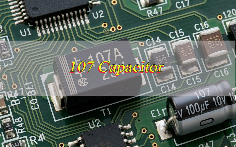
What Is a 107 Capacitor?
A 107 capacitor is a capacitor marked with the code “107,” which normally means 100 uF under the standard three-digit marking system. It is commonly used where a circuit requires energy storage, filtering, decoupling or voltage smoothing.
The same marking can appear on SMD tantalum capacitors, aluminum electrolytic capacitors, ceramic capacitors or polymer capacitors. Therefore, “107” explains the capacitance value, but it does not fully define the part.
In practical PCB repair and production, the 107 marking should be treated as the starting point, not the final specification. The full replacement also depends on voltage, tolerance, case size, polarity and reliability grade.
What Does It Mean If a Capacitor Says 107 On It?
If a capacitor says 107 on it, the marking usually means 100 uF. The code uses pF as the base unit, so 107 means 10 followed by 7 zeros in pF.
This marking is common on compact components because there is limited space for full printing. Instead of writing “100 uF,” the manufacturer may print “107,” sometimes followed by a letter such as A, C, D, E, J or K.
For example, 107A may mean a 100 uF capacitor with a specific voltage code, depending on the manufacturer. 107e capacitor code or 107a capacitor voltage must be checked against the actual datasheet because letter meanings can change between capacitor series.
How Do You Read a 107 Capacitor Code?
Read a 107 capacitor code by treating the first two digits as significant numbers and the third digit as the pF multiplier. In this case, “10” is the base number and “7” is the multiplier.
The calculation is simple:
10 × 10⁷ pF = 100,000,000 pF
100,000,000 pF = 100,000 nF
100,000 nF = 100 uF
This is why capacitor code 107 does not mean 107 pF. In most component marking systems, 107 is a coded capacitance value, not a direct number. When a capacitor says 107 on it, the correct first check is the capacitance code rule.
What Is the Value of a 107 Capacitor?
The 107 capacitor value is 100 uF when the marking follows the standard three-digit capacitor code. It equals 100,000 nF or 100,000,000 pF.
This value is often used in power filtering, bulk decoupling, voltage stabilization and low-frequency bypass circuits. In PCB assembly, 100 uF capacitors are often placed near power rails, DC input stages, regulators, motor drivers and embedded modules.
However, the value alone is not enough for replacement. A 100 uF 6.3 V tantalum capacitor cannot always replace a 100 uF 25 V electrolytic capacitor. The working voltage, ripple current, ESR and package size must match the circuit requirement.
Is a 107 Capacitor 107 pF or 100 uF?
A 107 capacitor is normally 100 uF, not 107 pF. This is one of the most common mistakes when reading capacitor markings.
The confusion happens because some users read the number as a direct value. For three-digit capacitor codes, the number must be decoded. The base unit is pF, and the last digit works as a multiplier.
A true 107 pF capacitor would usually be printed differently, such as “107 pF,” “107p,” or with another direct marking method. If the component is an SMD tantalum capacitor, ceramic capacitor or electrolytic capacitor marked “107,” it should usually be treated as 100 uF unless the datasheet says otherwise.
107 Capacitor Value in uF, nF and pF Conversion
The 107 capacitor conversion to uF is 100 uF. This conversion is useful when reading schematics, BOM files, datasheets, repair guides and PCB silkscreen notes.
| Code | uF | nF | pF |
|---|---|---|---|
| 107 | 100 uF | 100,000 nF | 100,000,000 pF |
A 107 capacitor value in uF is often written as 100 uF or 100MFD. In older documents, MFD usually means microfarad, not millifarad.
If a schematic shows capacitor 107 but the PCB footprint is small, confirm whether it is a tantalum, polymer or MLCC part. High-capacitance ceramic capacitors may lose effective capacitance under DC bias, so rated capacitance and actual in-circuit capacitance may differ.
What Types of 107 Capacitors Are Commonly Used?
A 100 uF capacitor with a 107 marking can be made in several common capacitor types, and each type has different performance, size and reliability behavior. The marking gives capacitance, while the type defines how the part behaves in a real circuit.
Common types include:
- Tantalum capacitor: compact, polarized, stable capacitance, common in SMD PCB assemblies.
- Aluminum electrolytic capacitor: polarized, cost-effective, common for power filtering and bulk storage.
- Polymer capacitor: low ESR, strong ripple performance, suitable for power rails.
- Ceramic capacitor: non-polarized, compact, but capacitance may drop under DC bias.
- Hybrid capacitor: combines stable ripple performance and improved reliability.
For replacement, match the original technology when the circuit is sensitive to ESR, leakage or ripple current.
Is a 107 Capacitor Polarized?
A 107 capacitor may be polarized or non-polarized, depending on its type. Tantalum, aluminum electrolytic and many polymer capacitors are polarized. Ceramic capacitors are usually non-polarized.
This matters because incorrect polarity can cause leakage, heating, swelling, short circuit or failure. On a tantalum capacitor, the polarity mark often indicates the positive side. On aluminum electrolytic capacitors, the stripe usually marks the negative side.
Before replacing a 107 SMD capacitor value part, check the PCB polarity mark, original component marking and schematic. If the capacitor sits across a DC power rail, polarity is usually critical. If it is used in a signal path, the circuit may require a non-polarized part.
What Voltage Ratings Are Available for 107 Capacitors?
Common voltage ratings for this 100 uF marking include 2.5 V, 4 V, 6.3 V, 10 V, 16 V, 20 V, 25 V, 35 V and 50 V, depending on capacitor type and series.
| Marking | Typical Meaning |
|---|---|
| 107A | 100 uF, often linked with 10 V in some tantalum series |
| 107C | 100 uF, often linked with 16 V in some tantalum series |
| 107D | 100 uF, often linked with 20 V in some tantalum series |
| 107E | 100 uF, often linked with 25 V in some tantalum series |
| 107J | 100 uF, often linked with 6.3 V in some tantalum series |
Letter codes are not universal. A 107a capacitor voltage or 107e capacitor code must always be verified by the manufacturer datasheet. For safer design, choose a voltage rating above the normal working voltage and consider derating for heat, surge and ripple.
107 Capacitor Datasheet Overview
A 107 capacitor datasheet should be checked before design, replacement or mass purchasing. The marking confirms capacitance, but the datasheet confirms whether the part fits the actual PCB application.
| Parameter | Typical Checkpoint |
|---|---|
| Capacitance | 100 uF |
| Tolerance | ±10%, ±20% or series-specific |
| Rated voltage | 2.5 V to 50 V range |
| Dielectric | Tantalum, ceramic, aluminum, polymer |
| Polarity | Polarized or non-polarized |
| ESR | Low ESR or standard ESR |
| Temperature | Often -55°C to +85°C or +125°C |
| Package | SMD case, radial, chip, molded |
| Ripple current | Series and size dependent |
| Qualification | RoHS, UL-related material check, customer standard |
For B2B procurement, the datasheet should match the BOM, approved vendor list, PCB footprint and reliability requirement before production.
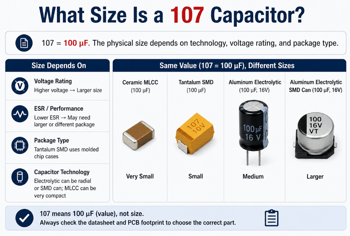
What Size Is a 107 Capacitor?
The size of a 107 capacitor depends on capacitance technology, voltage rating and package type. A 100 uF ceramic capacitor may be much smaller than a 100 uF electrolytic capacitor, while a higher-voltage part usually requires a larger case.
Common size factors include:
- Higher voltage rating usually increases body size.
- Lower ESR design may require a larger or different package.
- Tantalum SMD capacitors often use molded chip cases.
- Aluminum electrolytic capacitors may use radial or SMD can packages.
- Ceramic MLCC capacitors can be compact but may lose capacitance under DC bias.
If the question is “what size is a 107 capacitor,” the correct answer is: 100 uF is the value, but the physical size must be selected from the datasheet and PCB footprint.
What Is the Difference Between 106, 107 and 108 Capacitors?
106, 107 and 108 capacitors are different capacitance values. Each code follows the same first-two-digits plus multiplier rule.
| Code | Value | Common Reading |
|---|---|---|
| 106 | 10 uF | 10 × 10⁶ pF |
| 107 | 100 uF | 10 × 10⁷ pF |
| 108 | 1000 uF | 10 × 10⁸ pF |
A 107 capacitor has ten times the capacitance of a 106 capacitor and one-tenth the capacitance of a 108 capacitor.
In replacement work, do not change 106 to 107 unless the circuit allows higher capacitance. Larger capacitance can affect startup timing, inrush current, regulator stability and discharge behavior.
How to Choose the Right 107 Capacitor for Replacement?
Choose a 107 capacitor replacement by matching capacitance first, then checking voltage, polarity, package size, ESR, temperature rating and circuit function. A 100 uF value match is only the first requirement. The replacement part must also work safely in the same PCB position.
- Match the capacitance value:
A 107 capacitor normally equals 100 uF. Use the same capacitance unless the original circuit design allows a different value. Changing capacitance may affect startup timing, filtering performance or power stability. - Use equal or higher voltage rating:
Never replace the original part with a lower-voltage capacitor. If the circuit uses 12 V, a 16 V or 25 V capacitor is usually safer than a 10 V part, depending on size and design margin. - Confirm polarity before installation:
Tantalum, aluminum electrolytic and many polymer capacitors are polarized. Wrong polarity can cause leakage, overheating, short circuit or failure. Always check the PCB polarity mark before soldering. - Match the capacitor type:
Do not replace tantalum with ceramic or electrolytic parts without checking circuit behavior. Different capacitor types have different ESR, leakage current, ripple current and capacitance stability. - Check ESR and ripple current:
Power supply circuits may become unstable if ESR is too high or too low. For DC-DC converters, LED drivers and power rails, ESR and ripple current should be checked against the original datasheet. - Verify package size and footprint:
The replacement must fit the PCB pad, height limit and enclosure space. For SMD parts, confirm case code and polarity orientation. For radial parts, check lead spacing and body diameter. - Check temperature and reliability grade:
Industrial, automotive, LED and power applications may require 105°C or 125°C rated parts. Low-grade capacitors may pass initial testing but fail under heat, vibration or long operation. - Review datasheet before bulk replacement:
For production orders, confirm capacitance tolerance, rated voltage, ESR, leakage current, temperature range, package and compliance. Sample testing should be completed before mass PCB assembly.
What Applications Use 107 Capacitors?
A 100 uF capacitor marked 107 is commonly used in power filtering, decoupling, energy storage and voltage stabilization circuits. Its medium capacitance value makes it suitable for power support in many PCB assemblies.
Common applications include:
- DC-DC converter input and output filtering.
- MCU, IoT module and wireless module power rails.
- Automotive control boards and industrial PCB assemblies.
- LED driver circuits and power management boards.
- Battery-powered devices and charging circuits.
- Audio equipment, consumer electronics and embedded systems.
- Medical, communication and automation control PCB projects.
In these applications, capacitance value, voltage derating, ESR and ripple current directly affect stability. A wrong replacement may pass basic power-on testing but fail during load changes, temperature rise or long operation.
What Are Common 107 Capacitor Failure Problems?
Common failures include short circuit, capacitance loss, high ESR, leakage current, swelling, cracking and polarity damage. These problems often appear after heat stress, surge voltage or poor part selection.
Typical failure causes include:
- Voltage rating too close to the actual working voltage.
- Wrong polarity during PCB assembly or repair.
- Excessive ripple current in power circuits.
- High soldering temperature or long reflow exposure.
- Mechanical stress from PCB bending or poor placement.
- Low-quality parts from mixed or unverified sources.
- MLCC capacitance drop under DC bias in compact packages.
In factory production, incoming inspection, BOM control, soldering profile control and electrical testing reduce these risks before shipment.
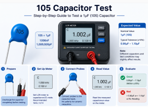
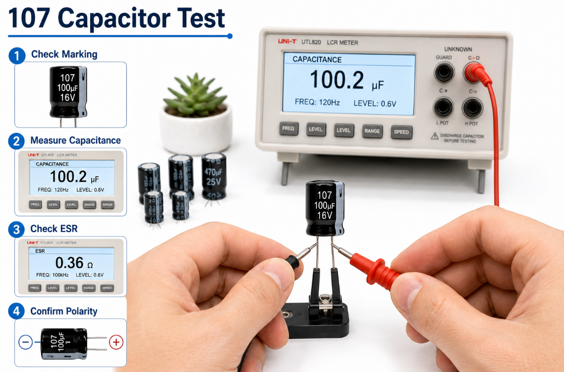
How Should 107 Capacitors Be Tested Before PCB Assembly?
107 capacitors should be tested before PCB assembly to confirm value, polarity, package, electrical performance and soldering reliability. This prevents wrong parts, unstable power rails and batch assembly defects.
Step 1: Check the part marking and label.
Confirm the reel label, part number, date code, manufacturer name and visible capacitor marking. The “107” marking should match the BOM, datasheet and approved vendor list.
Step 2: Confirm the capacitance value.
Use an LCR meter or capacitance meter to check whether the part is close to 100 uF within tolerance. The test condition should follow the datasheet, especially for ceramic or high-capacitance parts.
Step 3: Verify voltage rating and capacitor type.
Check whether the part is tantalum, ceramic, aluminum electrolytic or polymer. Then confirm the rated voltage is suitable for the actual PCB power rail and has enough design margin.
Step 4: Inspect polarity and package size.
For polarized capacitors, confirm the positive and negative marks before SMT placement. Also check case size, height, footprint match and orientation to avoid assembly errors.
Step 5: Test ESR and leakage current when required.
Power circuits, DC-DC converters and filtering circuits often require ESR control. High leakage current or wrong ESR can cause heating, unstable startup or poor voltage regulation.
Step 6: Check solderability and storage condition.
Inspect terminals, oxidation, moisture sensitivity, packaging condition and shelf life. Poor storage may reduce solderability and cause weak solder joints during PCB assembly.
Step 7: Run first-article PCB assembly verification.
Before batch production, assemble a small sample and check polarity, solder joints, reflow condition and power-on behavior. This step helps catch BOM, footprint or process issues early.
Step 8: Perform functional testing after assembly.
After soldering, test the PCB under normal load. Check input voltage, output ripple, startup behavior, temperature rise and stability. For critical boards, aging or burn-in testing can be added.
What Should Buyers Check Before Ordering 107 Capacitors in Bulk?
Bulk buyers should check datasheet consistency, original manufacturer, voltage rating, package size, shelf life, moisture control and compliance documents. This prevents production delay and field failure.
Important purchasing checks include:
- Confirm the exact part number, not only “107.”
- Match voltage code, tolerance and dielectric series.
- Request RoHS and material compliance when required.
- Check reel packaging, date code and storage condition.
- Avoid unknown substitutions without engineering approval.
- Confirm long-term supply stability for repeat PCB orders.
- Test samples before full batch assembly.
For cross-border buyers, a China source factory can support BOM review, alternative component sourcing, PCB assembly verification and global shipment without claiming local warehouses or overseas branches.
Case Study: Replacing a 107 Tantalum Capacitor in a Power Rail
A customer’s control PCB used a 107 tantalum capacitor near a 5 V power input. The original part was marked 107A, but the replacement supplier provided a different 100 uF part with lower voltage margin and different ESR.
During testing, several boards showed unstable startup and occasional heating. After review, the problem was not the capacitance value. The issue came from voltage derating, ESR mismatch and unclear polarity confirmation during repair.
The solution was to select a 100 uF capacitor with suitable voltage margin, correct case size, verified polarity marking and stable supply. Sample testing confirmed normal startup, lower heat and consistent load response before batch replacement.
Why Work With EBest for PCB Assembly and Component Sourcing?
EBest supports PCB manufacturing, PCB assembly and component sourcing for global buyers who require stable production, practical engineering support and controlled quality. We operate as a China source factory and global supply manufacturer, without false overseas warehouse or local branch claims.
For capacitor replacement projects, our team can help check BOM details, package compatibility, polarity risk, soldering process and component sourcing options before mass production. This reduces trial-and-error cost during PCB assembly.
We can support prototype builds, small-batch validation, volume production and sourcing review for industrial, IoT, LED, communication, medical and control electronics. Buyers can send Gerber files, BOM, assembly drawings and test requirements for engineering review and quotation.
FAQs About 107 Capacitors
Q1: Can I replace a 107 capacitor with a 100 uF capacitor?
A1: Yes. A 107 capacitor normally equals 100 uF, so a 100 uF capacitor can be used if the voltage rating, polarity, ESR, package size and temperature rating match the original circuit.
Q2: Why does my capacitor show 107 and 10K together?
A2: The “107” usually means 100 uF. The “10K” may refer to tolerance, voltage, date code or manufacturer-specific information. Always confirm the full marking through the datasheet.
Q3: What does 107 16K capacitor mean?
A3: It often indicates a 100 uF capacitor with a 16 V rating and a tolerance or series code. However, marking rules vary, so the exact manufacturer datasheet should be checked.
Q4: What does capacitor 107 20K mean?
A4: In many cases, it points to a 100 uF capacitor with a 20 V class or related voltage code. The “K” may indicate tolerance or series marking, depending on the brand.
Q5: Is 107 SEPC 220 16 capacitor the same as a normal 107 capacitor?
A5: Not exactly. “107” means 100 uF, while SEPC and 220 16 may indicate series, ESR, ripple rating or voltage details. These parameters affect power circuit performance.
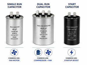
Q6: Is a 107-129 MFD start capacitor the same as a 107 capacitor code?
A6: No. A 107-129 MFD start capacitor usually means a motor start capacitor with a capacitance range from 107 uF to 129 uF. A 107 capacitor code normally means 100 uF.
Q7: What does capacitor 107-129 MFD mean on a motor start capacitor?
A7: It means the motor start capacitor is rated for a capacitance range of 107 to 129 microfarads. This is a range marking, not the same as the three-digit 107 capacitor code.
Q8: Can a 107 ceramic capacitor replace a 107 tantalum capacitor?
A8: Not always. Both may be 100 uF, but ceramic capacitors can lose capacitance under DC bias, while tantalum parts have polarity and ESR behavior that may suit the original design.
Q9: What does 107 marking mean on a tantalum capacitor?
A9: A 107 tantalum capacitor marking usually means 100 uF. Extra letters or numbers identify voltage, tolerance, case size or series. Because tantalum capacitors are usually polarized, polarity must be checked.
Q10: Is a 107 ceramic capacitor value always 100 uF?
A10: In standard three-digit marking, 107 equals 100 uF. However, ceramic capacitors may lose effective capacitance under DC bias, so actual working capacitance can be lower in live circuits.
Q11: What does 107 capacitor marking mean on SMD parts?
A11: On many SMD parts, 107 means 100 uF. Extra letters or numbers may show voltage, tolerance, series or manufacturing code. Package size must be checked before replacement.
Q12: Can I use a higher voltage 107 capacitor?
A12: Yes, a higher voltage rating is usually acceptable if the size, ESR, polarity and package fit. Do not use a lower voltage rating than the original design requirement.
Q13: Why did my replacement 107 capacitor fail quickly?
A13: Common reasons include wrong polarity, low voltage margin, high ripple current, poor ESR match, excessive heat or low-quality sourcing. The value 100 uF alone does not guarantee compatibility.
Q14: How do I test a 107 capacitor with a meter?
A14: Use a capacitance meter or LCR meter to check whether it is close to 100 uF. For power circuits, ESR and leakage testing provide a more reliable health check.
Conclusion
A 107 capacitor is normally a 100 uF capacitor, not a 107 pF capacitor. The marking explains capacitance, but a safe design or replacement must also confirm voltage rating, polarity, capacitor type, ESR, temperature range, package size and datasheet limits.
For engineering selection, do not replace a capacitor only by matching the “107” code. Check the circuit function, power rail voltage, ripple load, reflow process and PCB footprint before approving the part. For purchasing, confirm the exact manufacturer series, compliance documents, date code and supply stability before bulk orders.
EBest Circuit supports PCB manufacturing, PCB assembly, BOM review, component sourcing and global supply from our China source factory. For 107 capacitor replacement, PCB assembly projects or batch production quotation, send your files and requirements to sales@bestpcbs.com.