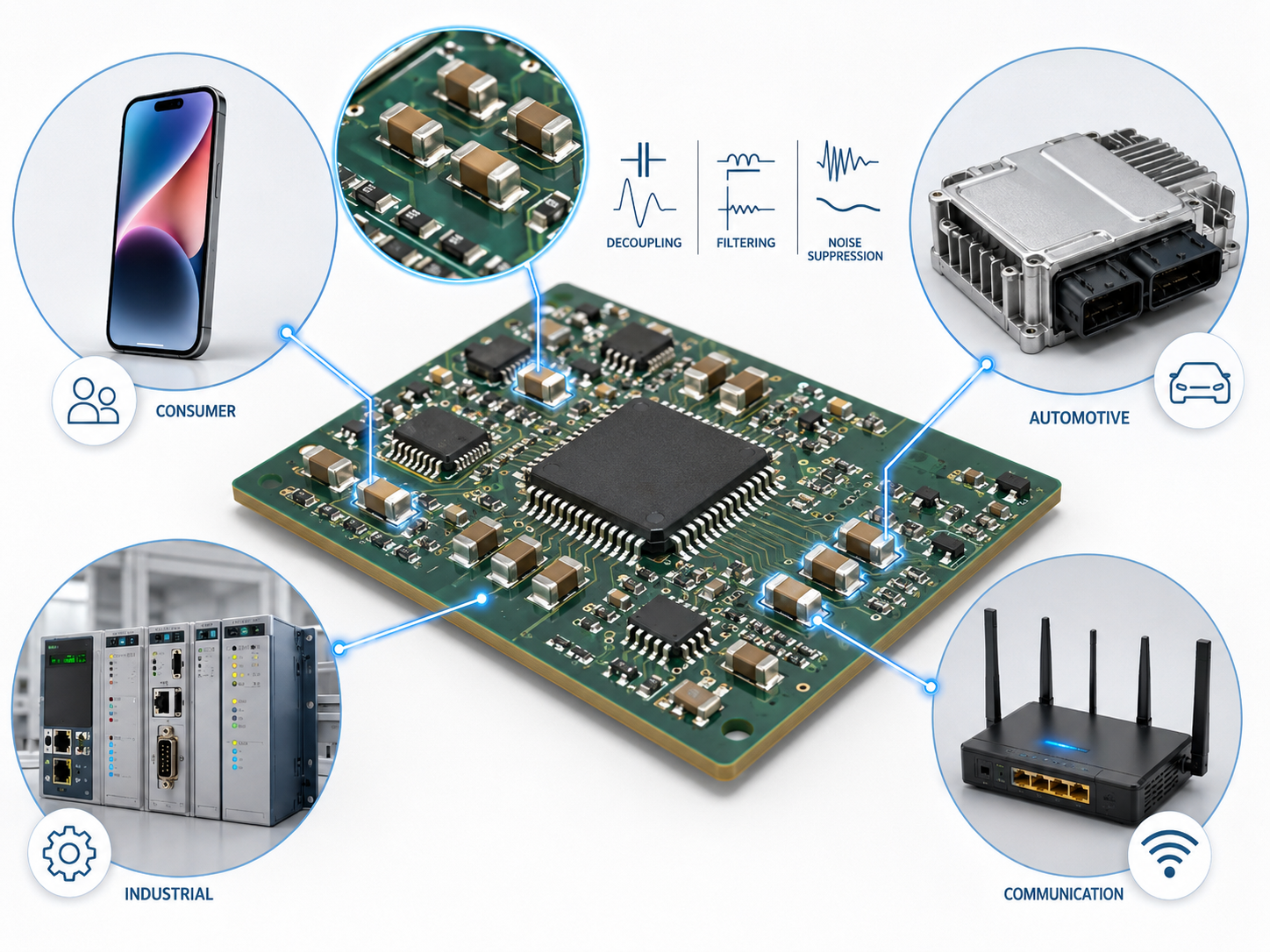
An MLCC capacitor is one of the most widely used passive components in modern electronics. It is small, stable, fast, and suitable for many PCB designs, from consumer devices to automotive control modules, industrial power supplies, communication equipment, medical electronics, and high-density embedded systems.
The full form of MLCC is multilayer ceramic chip capacitor. In many datasheets, it is also described as a multilayer ceramic capacitor MLCC or MLCC multilayer ceramic capacitor. The name already explains its structure: several ceramic dielectric layers and metal electrode layers are stacked inside one compact chip.
What Is a MLCC Capacitor?
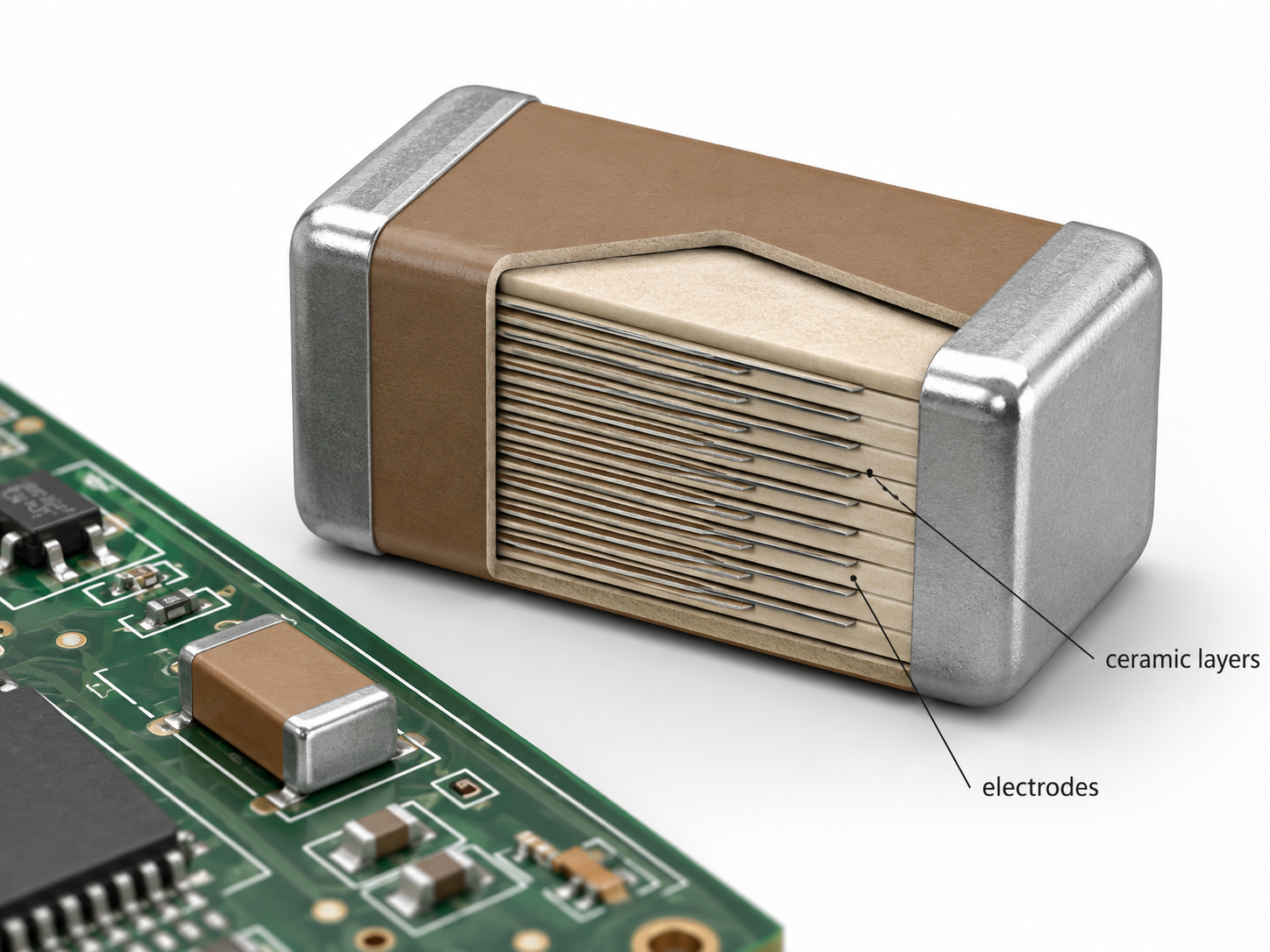
Unlike normal ceramic capacitor like 104 capacitor, or 103 capacitor, a MLCC capacitor is made by stacking many thin ceramic dielectric layers and internal metal electrodes. These layers are pressed, sintered, terminated, plated, tested, and packed into a surface-mount component.
Its main job is to store and release electrical energy in a circuit. In real PCB design, MLCCs are commonly used for decoupling, bypassing, filtering, timing, coupling, noise suppression, and power rail stabilization.
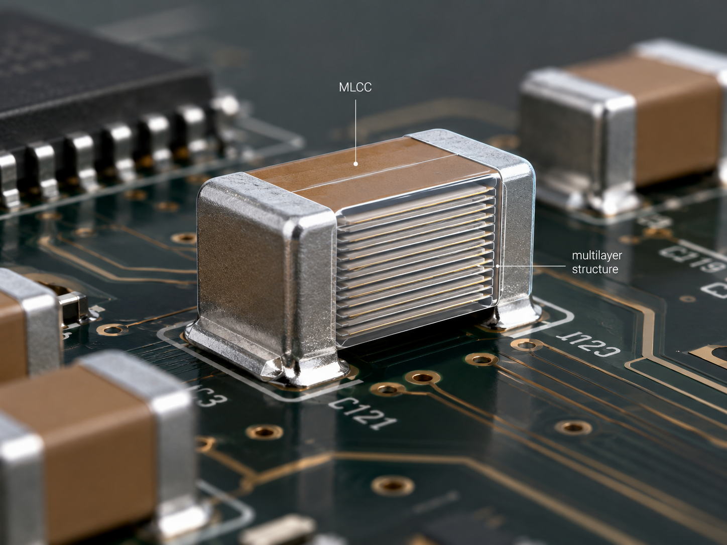
Compared with many older capacitor styles, MLCCs offer high capacitance density in a very small footprint. TDK notes that advanced MLCC manufacturing can use precise multilayer structures with very thin dielectric layers and many stacked layers, which helps achieve compact size and high capacitance.
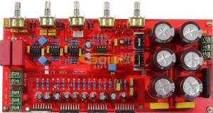
What Do MLCC Capacitors Look Like?
Most mlcc capacitors on modern PCBs are small rectangular surface-mount chips. They usually have a light beige, cream, brown, or grey ceramic body with metal terminations on both ends.
A typical surface-mount MLCC has:
- A rectangular ceramic body
- Nickel or tin-plated end terminals
- No printed polarity mark
- No long lead wires
- Standard chip sizes such as 0402, 0603, 0805, 1206, and larger packages
Some MLCCs are extremely small and may be difficult to identify without magnification. On a dense PCB, they often sit close to IC power pins, connectors, oscillators, RF circuits, and power management devices.
- Inductor on PCB: Placement, Selection, Footprint and EMI Guidelines
- PCB Prototype Service: Quick PCB and PCBA Prototyping
- Silicone Encapsulants for Electronics | PCB Potting Guide
- Parts of a PCB: Components, Functions, and Identification
- HDI PCB Design Review: Stackup, Microvia and DFM Checks
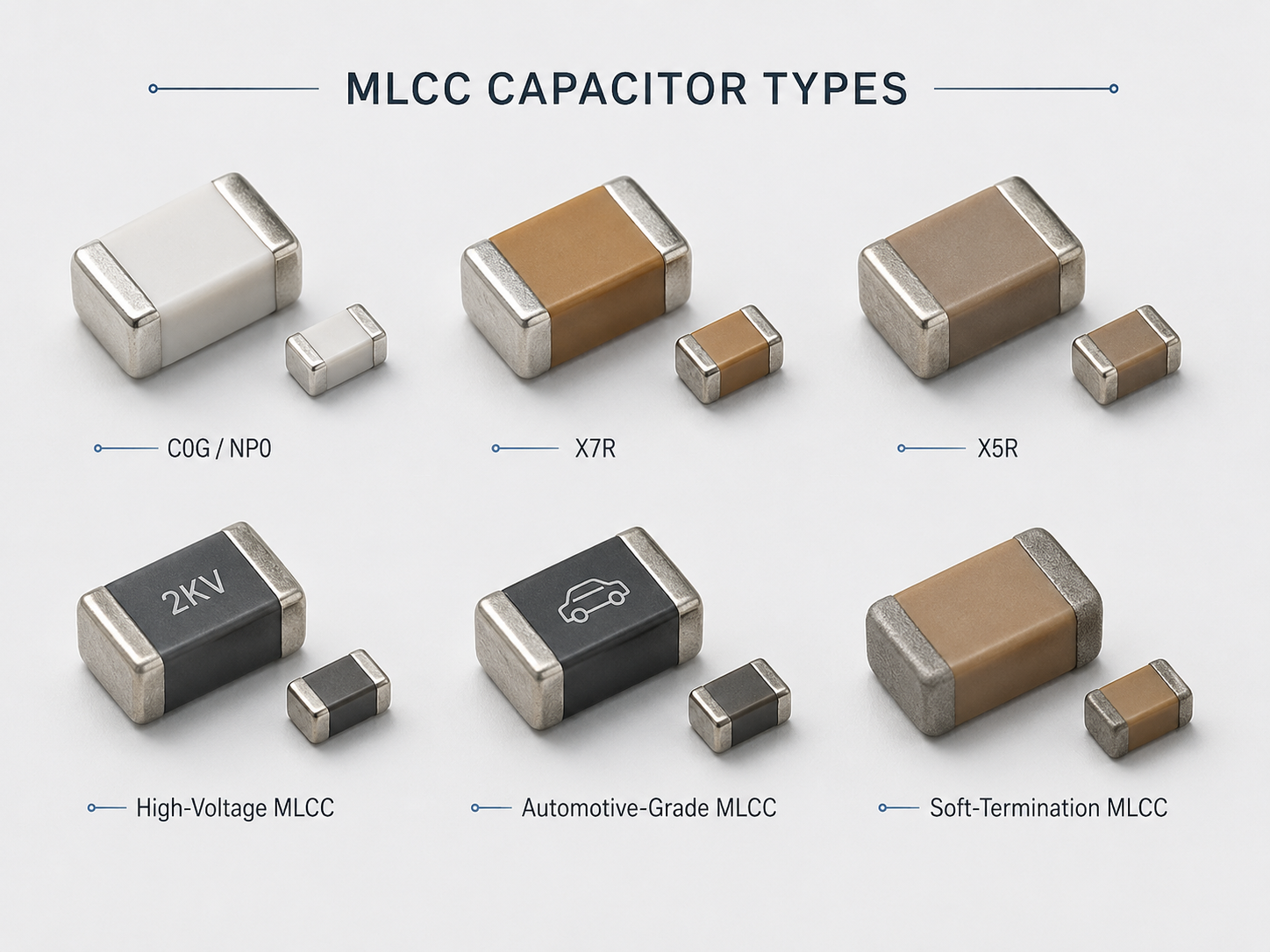
MLCC Capacitor Types
MLCC capacitor types are often classified by dielectric material, application grade, termination structure, voltage rating, and package size. Among these, dielectric type is one of the most important selection factors because it affects capacitance stability, temperature behavior, aging, DC bias performance, and circuit accuracy. Common MLCC dielectric types including:
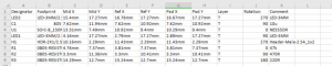
| Dielectric Type | General Class | Main Feature | Typical Use |
|---|---|---|---|
| C0G / NP0 | Class I | Very stable, low loss, low aging | RF circuits, filters, oscillators, timing |
| X7R | Class II | Good capacitance density, moderate stability | Decoupling, bypassing, general electronics |
| X5R | Class II | High capacitance in compact size | Power rail decoupling, portable devices |
| X7S / X8R | Class II | Wider temperature options depending on type | Automotive, industrial, high-temperature areas |
| Y5V / Z5U | Class III | High capacitance, lower stability | Low-cost, non-critical applications |
For precision circuits, C0G/NP0 is usually preferred because it has better temperature stability and lower loss. For power decoupling, X7R and X5R are common because they provide higher capacitance in compact packages.
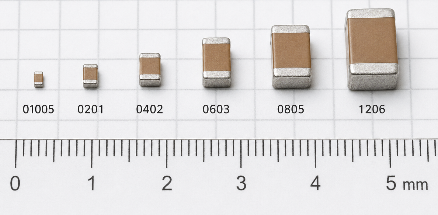
MLCC Capacitor Sizes
MLCC capacitor sizes are usually described by EIA case codes. The code represents the length and width of the component in inches. For example, 0603 means approximately 0.06 inch × 0.03 inch.
| EIA Size | Metric Approx. | Typical Use |
|---|---|---|
| 008004 | 0.25 × 0.125 mm | Ultra-miniature mobile and wearable devices |
| 01005 | 0.4 × 0.2 mm | Smartphones, compact modules |
| 0201 | 0.6 × 0.3 mm | High-density electronics |
| 0402 | 1.0 × 0.5 mm | General compact PCB design |
| 0603 | 1.6 × 0.8 mm | Common decoupling and filtering |
| 0805 | 2.0 × 1.25 mm | Higher capacitance and easier assembly |
| 1206 | 3.2 × 1.6 mm | Power circuits, industrial boards |
| 1210 | 3.2 × 2.5 mm | Higher capacitance or voltage |
| 1812 / 2220 | Larger packages | High-voltage, high-capacitance, special applications |
Smaller MLCCs save PCB space, but they are not always better. Very small packages may have lower effective capacitance under DC bias, tighter assembly requirements, and higher sensitivity to placement and soldering process control.
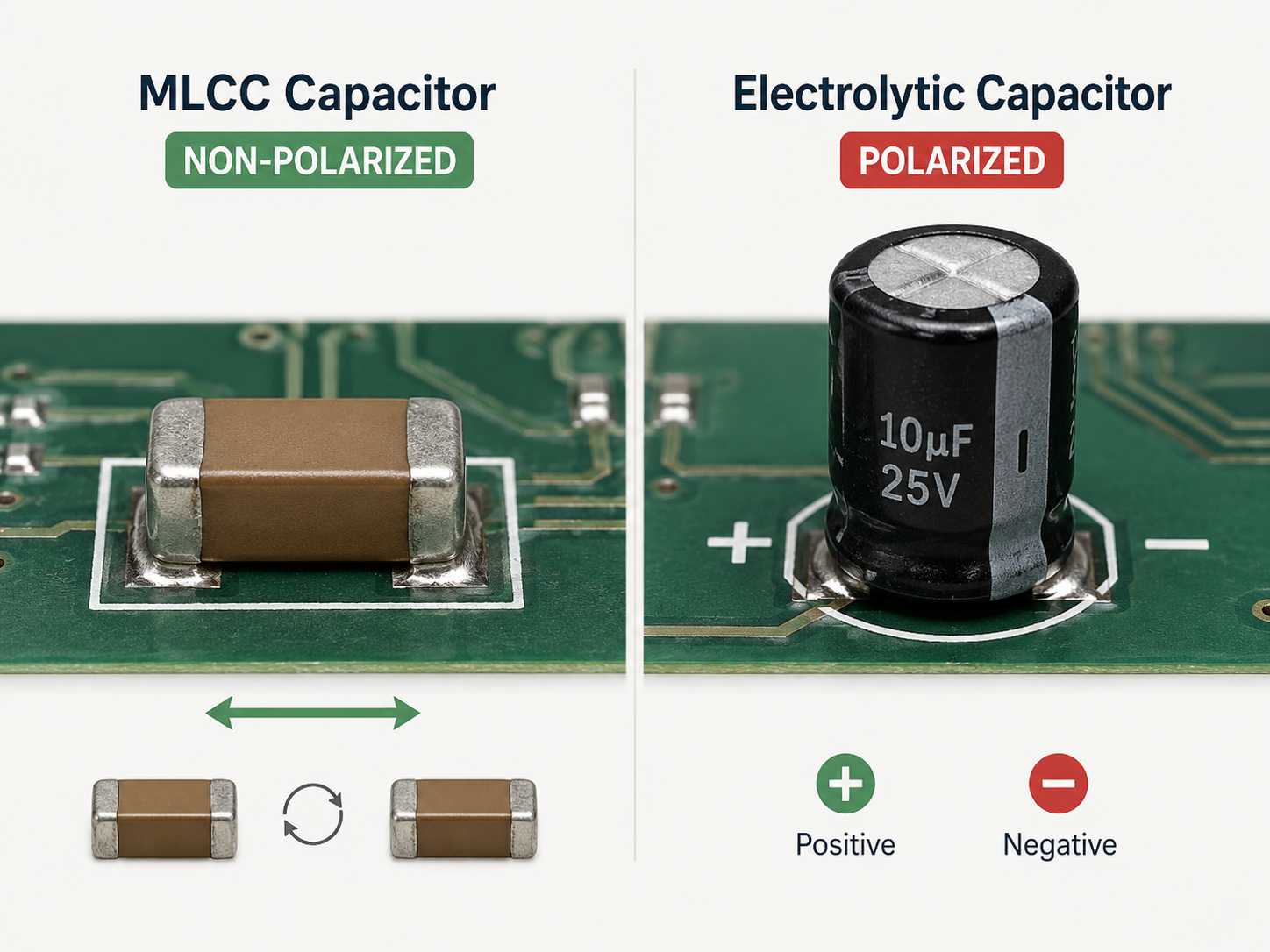
Do MLCC Have Polarity?
No. Standard MLCC capacitors are non-polarized. They can usually be mounted in either direction because their internal structure does not have a fixed positive or negative terminal. However, non-polarized does not mean “no design limits.” An MLCC still has:
- Rated voltage
- Capacitance tolerance
- Temperature range
- Insulation resistance
- Ripple current limit
- Mechanical stress limit
- Soldering process requirements
So, while polarity is not a concern, electrical and mechanical derating still matters.
How Does MLCC Work?
An MLCC works by storing energy in an electric field between internal electrode layers. The ceramic dielectric separates the electrodes and allows the capacitor to hold charge.
Inside the component, alternating electrode layers are connected to opposite end terminations. This creates many small capacitors connected in parallel within one chip. The multilayer structure increases the total effective electrode area, which helps achieve useful capacitance in a compact package.
A simple working principle is:
1. Voltage is applied across the two terminals.
2. Charge builds up on the internal electrode plates.
3. The ceramic dielectric stores energy in the electric field.
4. The capacitor releases charge when the circuit requires it.
5. High-frequency noise can be bypassed through the capacitor path.
In power circuits, MLCCs are often placed near IC power pins to reduce supply ripple and transient voltage dips. In signal circuits, they may be used for filtering, coupling, or timing, depending on capacitance value and dielectric type.
What Are the Advantages of Using MLCCs?
MLCCs are popular because they offer a strong combination of size, performance, reliability, and cost efficiency. Key advantages include:
- Small size and high capacitance density
- Low ESR and low ESL
- Non-polarized mounting
- Good reliability when properly selected
- Wide product range
- Suitable for automated SMT assembly
What Are the Disadvantages of MLCCs?
MLCCs are powerful components, but they have limitations. These limits are important in practical PCB and PCBA work, for example:
1. Capacitance drops under DC bias
For many Class II MLCCs, the actual capacitance can decrease when DC voltage is applied. This means a 10 µF capacitor may deliver much less effective capacitance in the real circuit, depending on package size, voltage rating, dielectric, and applied voltage. Infineon describes MLCC DC bias as capacitance change caused by applied DC voltage.
2. Aging in Class II dielectrics
X7R, X5R, and similar dielectrics can lose capacitance over time due to dielectric aging. TDK explains that this aging is a reversible capacitance decrease in EIA Class II capacitors.
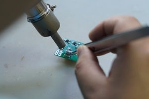
3. Risk of cracking
MLCCs are ceramic and can crack under PCB bending, thermal shock, poor depanelization, excessive solder, or mechanical stress. Murata states that mechanical stress and thermal stress during or after mounting are main causes of chip MLCC cracking.
How Are MLCC Capacitors Made?
MLCC manufacturing is a precision ceramic and metallization process. Although each manufacturer has its own process details, the common production flow is similar.A simplified process is:
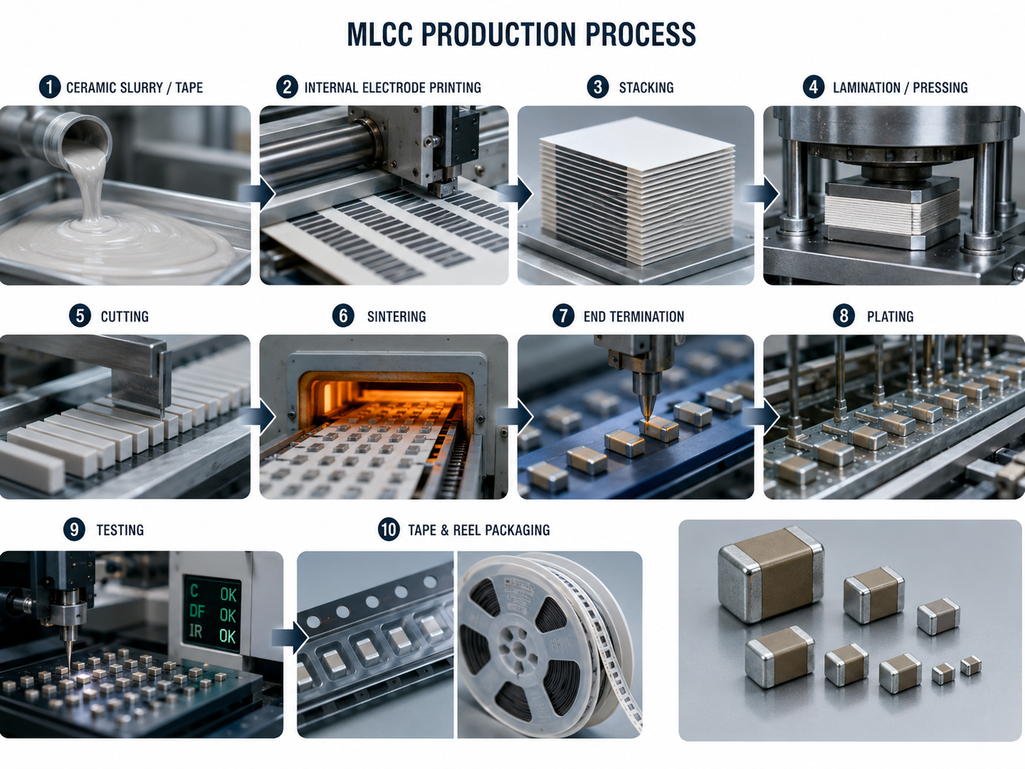
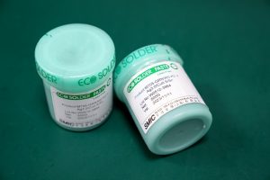
1. Ceramic powder preparation
Fine ceramic powder is mixed with organic binders and solvents to form a slurry.
2. Tape casting
The slurry is formed into thin ceramic sheets.
3. Internal electrode printing
Metal electrode paste is printed onto the ceramic sheets.
4. Stacking
Printed sheets are stacked in alternating electrode patterns.
5. Pressing
The stack is pressed to form a compact block.
6. Cutting
The block is diced into individual capacitor chips.
7. Sintering
Chips are fired at high temperature to form a dense ceramic body.
8. Termination
Outer electrodes are applied to both ends.
9. Plating
Nickel and tin layers are commonly plated to improve solderability.
10. Testing and packaging
Capacitance, insulation resistance, withstand voltage, dimensions, and appearance are checked before tape-and-reel packaging.
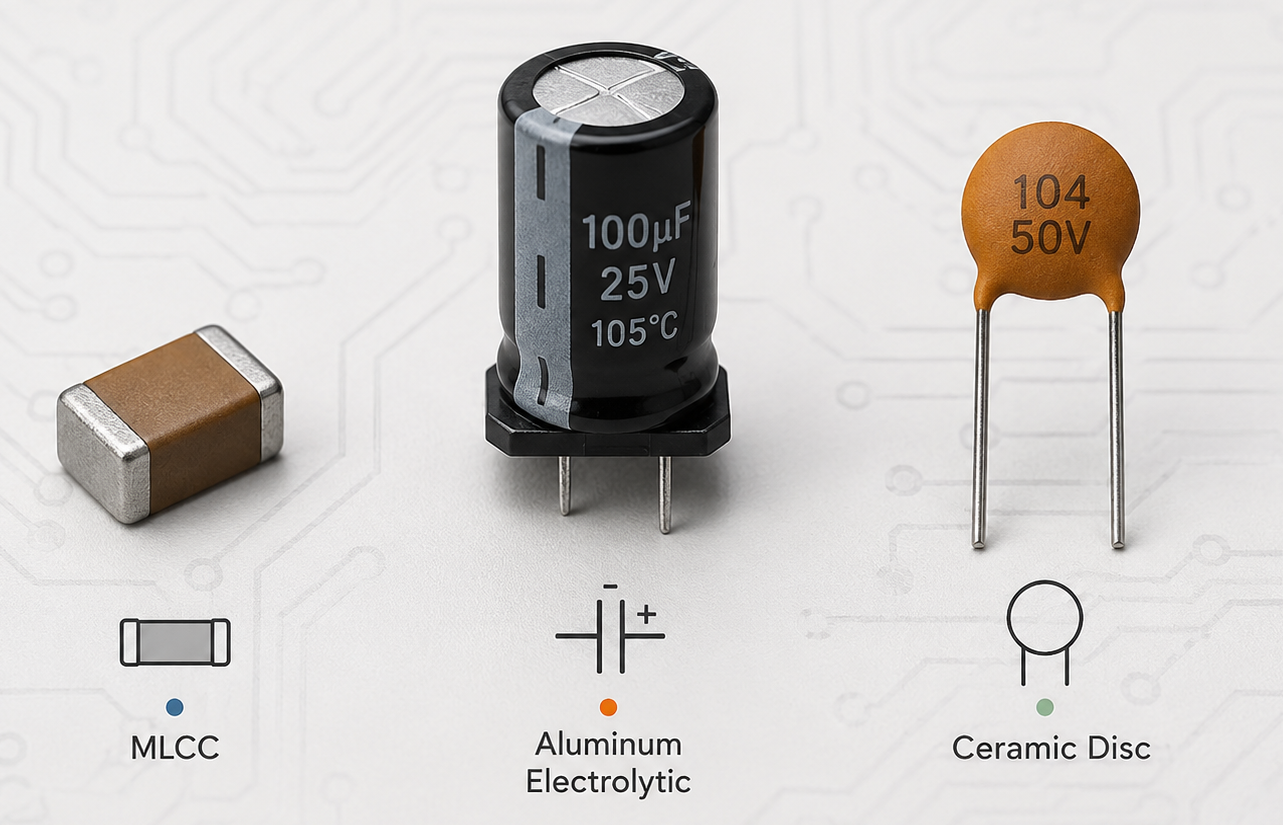
Are MLCC and Electrolytic Capacitors Equivalent?
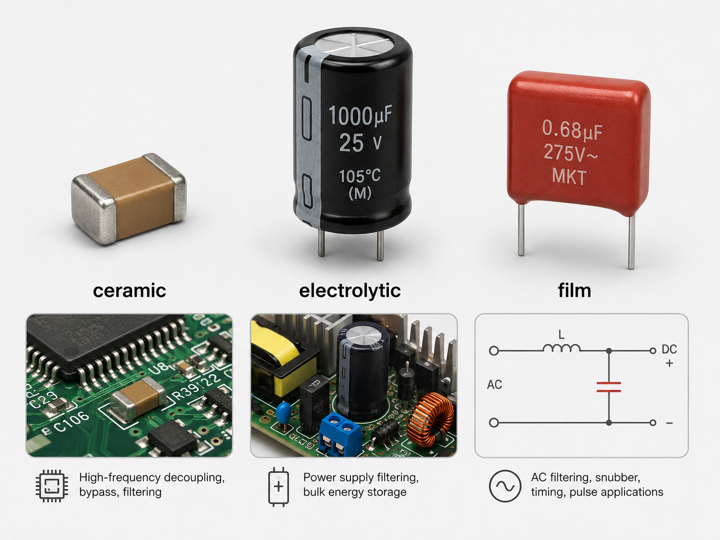
MLCC and electrolytic capacitors are not fully equivalent, although they can sometimes perform similar roles.
An electrolytic capacitor is often used for bulk energy storage, low-frequency ripple smoothing, and larger capacitance values. An MLCC is often used for high-frequency decoupling, fast transient response, compact filtering, and local bypassing.
| Item | MLCC | Electrolytic Capacitor |
|---|---|---|
| Polarity | Non-polarized | Usually polarized |
| ESR | Very low | Higher |
| Size | Very compact | Larger for similar capacitance |
| Capacitance range | pF to hundreds of µF depending on type | µF to thousands of µF |
| DC bias effect | Important for Class II MLCCs | Usually less comparable |
| Aging behavior | Class II ceramics age | Electrolyte may dry over time |
| Best use | High-frequency decoupling, compact PCBs | Bulk storage, low-frequency smoothing |
In many circuits, designers use both. For example, a power input may use an electrolytic capacitor for bulk capacitance and several MLCCs near ICs for high-frequency decoupling.
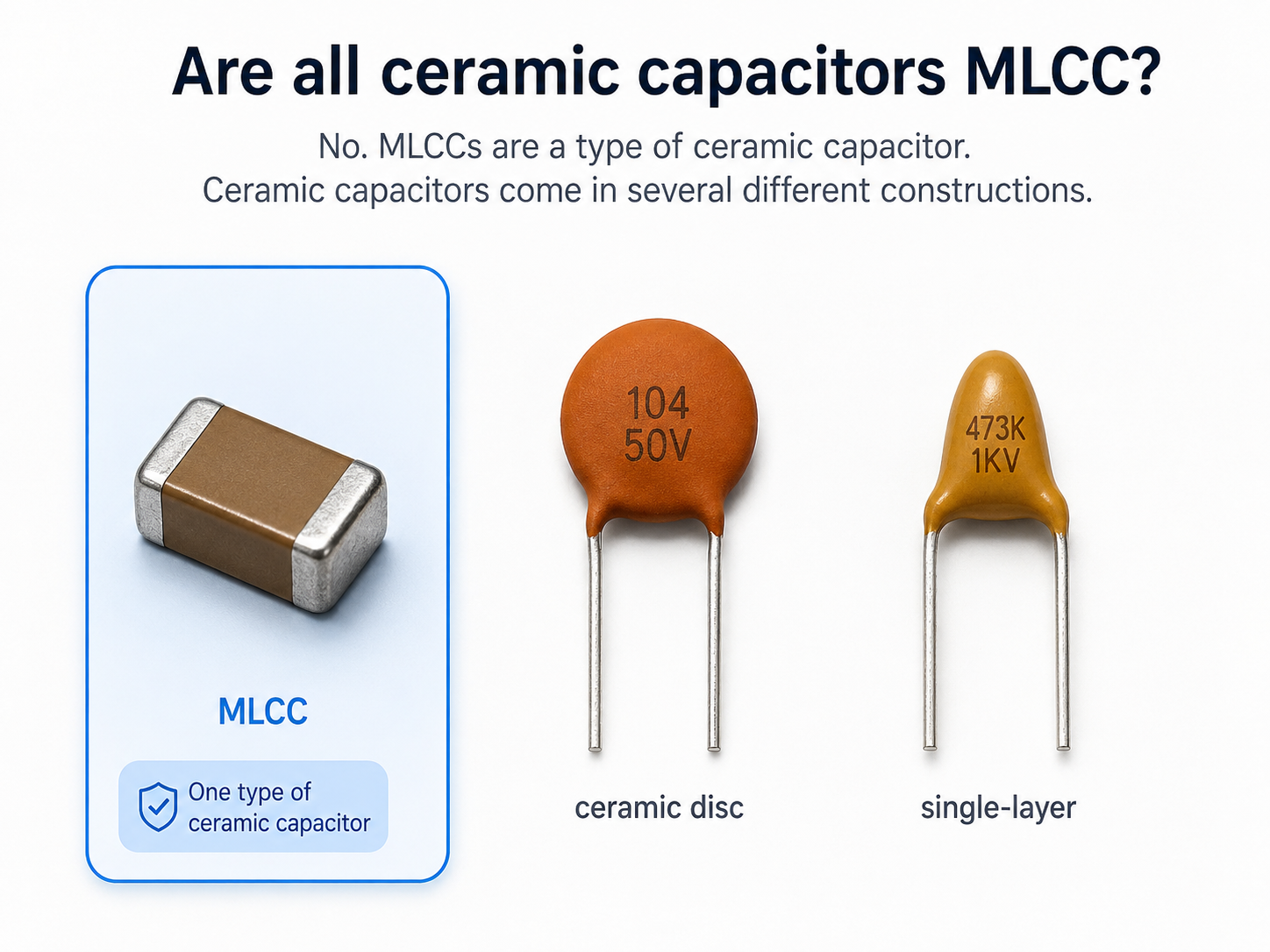
What Is the Difference Between MLCC and Disc Capacitor?
Both MLCCs and disc capacitors are ceramic capacitors, but their construction and usage are different.
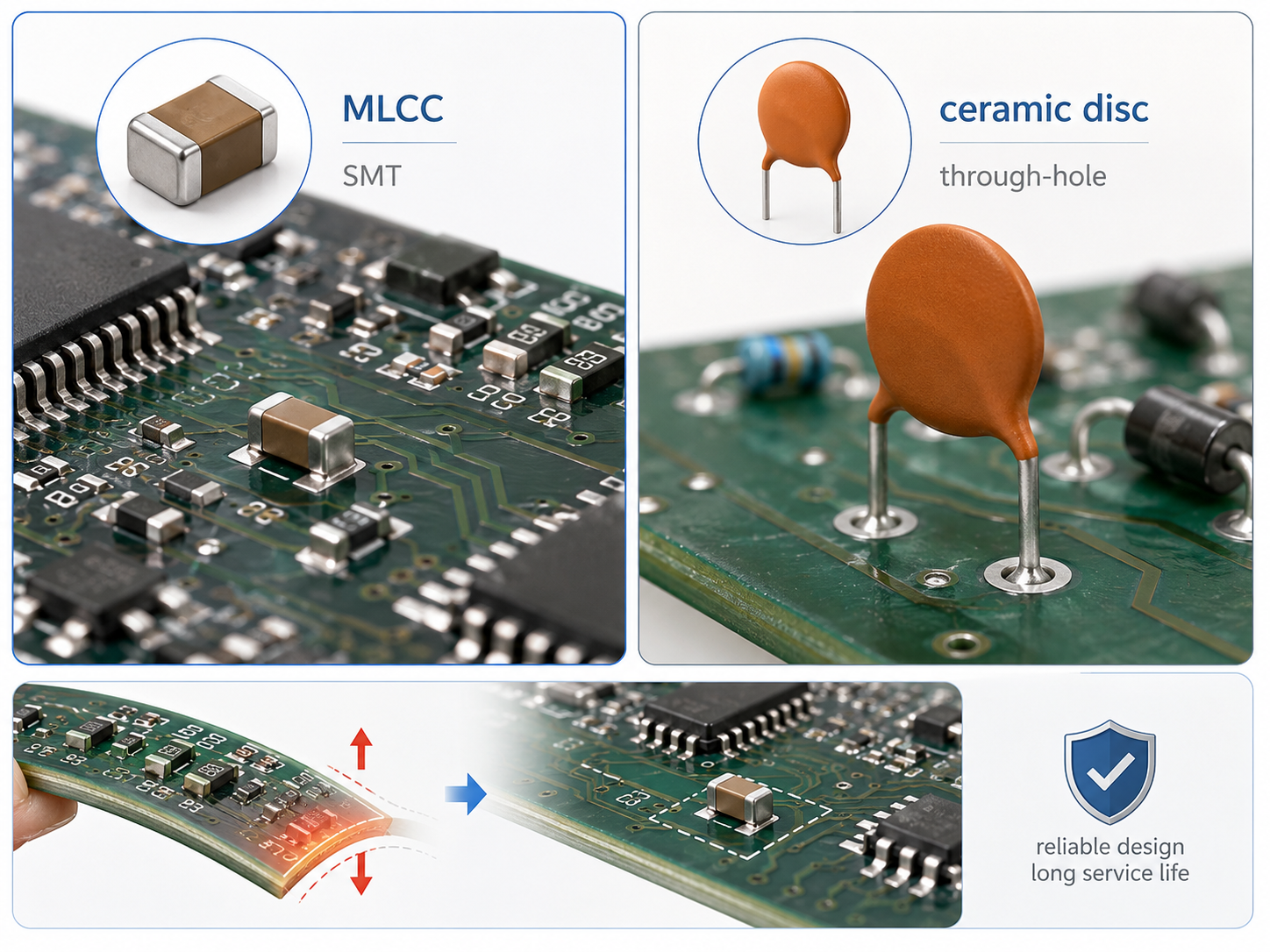
An MLCC uses a multilayer chip structure. It is usually surface-mounted and designed for compact, high-density PCB layouts.
A ceramic disc capacitor is usually a single-layer or simpler ceramic structure with radial leads. It is often used in through-hole circuits, older designs, safety capacitors, high-voltage circuits, or low-cost general applications.
MLCCs are usually preferred in modern compact electronics. Disc capacitors are still useful when leaded mounting, high-voltage spacing, or special safety ratings are needed.
What Is MLCC Used For?
MLCCs are used almost everywhere in electronics. Their role depends on capacitance, dielectric, package, voltage rating, and circuit location.
Common applications include:
- Power rail decoupling
- Bypass capacitors
- Filtering circuits
- RF circuits
- Automotive electronics
- Industrial control boards
- Consumer electronics
Samsung Electro-Mechanics notes that MLCCs charge and discharge electricity and highlights their growing importance in electronic devices, self-driving cars, IoT, and 5G-era applications.
What Causes Cracks in MLCC?
Cracking is one of the most important MLCC failure risks. Because MLCCs are ceramic, they are strong under compression but sensitive to bending and thermal stress.
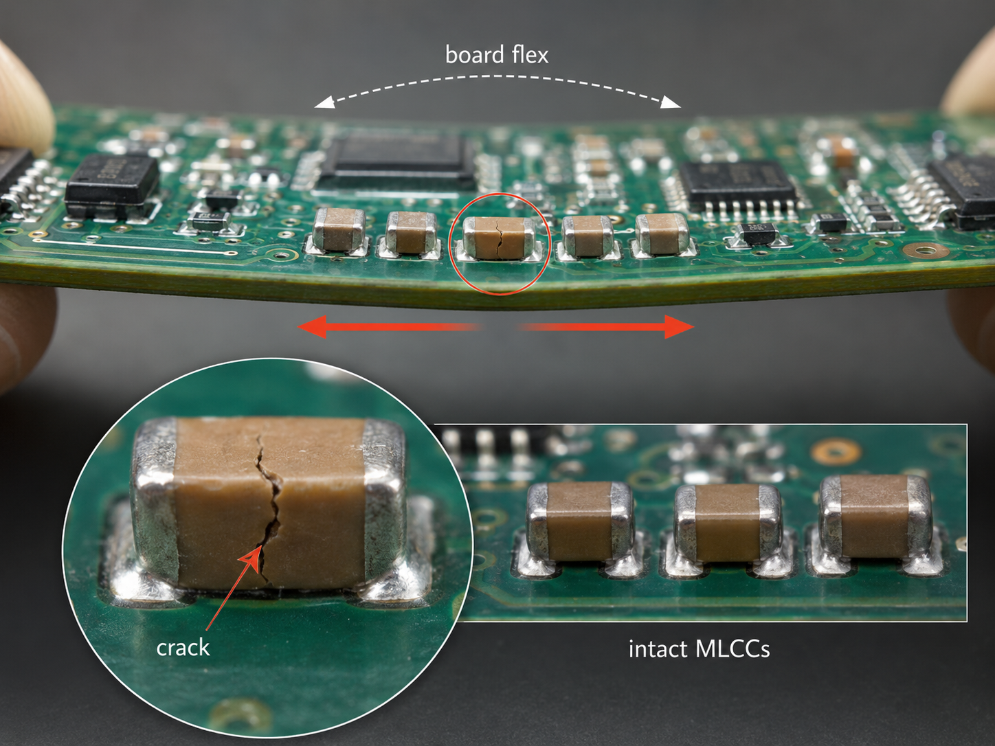
Common causes include:
PCB bending
Board flex during assembly, testing, screw fastening, connector insertion, depanelization, or product use can crack the ceramic body.
Poor depanelization
Breaking boards manually or using improper V-cut separation can create local stress near mounted MLCCs.
Thermal shock
Fast temperature changes during soldering, rework, cleaning, or wave soldering can damage the ceramic body.
Excessive solder volume
Too much solder can increase mechanical stress on the termination and ceramic body.
Wrong component placement
Large MLCCs placed near board edges, screw holes, connectors, or cut lines face higher bending stress.
Drop and vibration
Portable, automotive, and industrial products may experience shock or vibration after shipment or during service.
Practical prevention methods include using smaller package sizes where suitable, placing MLCCs away from high-stress areas, aligning parts properly, adding slots or stress relief where needed, using soft-termination MLCCs, controlling solder volume, and improving depanelization fixtures.
Top 5 MLCC Capacitor Manufacturers
1. Murata Manufacturing
Murata is one of the best-known names in ceramic capacitors and has a broad MLCC product portfolio. Its ceramic capacitor lineup covers many application areas, including consumer electronics, industrial equipment, automotive electronics, and high-reliability designs.
Murata MLCC capacitors are often selected when engineers need broad availability, strong technical documentation, high reliability options, and stable long-term supply.
2. Samsung Electro-Mechanics
Samsung Electro-Mechanics is a major MLCC manufacturer with strong capability in high-capacity and compact MLCC production. Its MLCC introduction page describes MLCCs as devices that charge and discharge electricity and notes the importance of stacking many thin layers inside a compact structure.
Samsung MLCC products are widely used in consumer electronics, communication equipment, automotive electronics, and IoT-related designs.
3. TDK
TDK is another major supplier of multilayer ceramic chip capacitors. TDK highlights advanced material technology, precise electrode placement, and high-layer-count structures for compact MLCC designs.
TDK is also known for strong application resources, including guidance on flex cracking, aging, and capacitor selection.
4. Taiyo Yuden
Taiyo Yuden manufactures multilayer ceramic capacitors for compact and high-reliability applications. The company describes MLCCs as ultra-small, low-profile components with alternating ceramic and electrode layers.
Taiyo Yuden is often considered in compact electronics, communication equipment, industrial devices, and high-capacitance MLCC applications.
5. Yageo Group
Yageo Group is a major passive component supplier with a wide capacitor portfolio, including MLCCs. Yageo states that its MLCCs are designed for diverse applications from RF to power decoupling and offer low ESR/ESL options.
Yageo Group also includes KEMET-related capacitor capabilities, making it an important supplier for automotive, industrial, and general electronic applications.
How Do You Select the Right MLCC?
Selecting the right MLCC requires more than choosing a capacitance value. A good selection process should match the real working condition of the PCB.
1. Confirm capacitance value under real conditions
Do not only read the nominal value. Check capacitance under DC bias, temperature, frequency, and aging. For Class II MLCCs, the effective capacitance can be much lower than the rated value in actual operation.
2. Choose the right dielectric
Use C0G/NP0 for high stability, RF, timing, and precision circuits. Use X7R or X5R for general decoupling and bypassing where higher capacitance is needed. Avoid low-stability dielectrics in circuits that require predictable capacitance.
3. Check voltage rating and derating
The rated voltage should be higher than the actual working voltage. For many designs, designers apply voltage derating to improve reliability and reduce capacitance loss.
4. Match package size with PCB and assembly needs
A smaller MLCC saves space, but a larger package may provide higher capacitance, higher voltage rating, or better availability. Large packages can also be more sensitive to board flex, so mechanical placement matters.
5. Review temperature range
For automotive, industrial, LED lighting, and power electronics, choose MLCCs with suitable operating temperature ratings. Check whether the capacitor remains stable across the full environment.
6. Consider mechanical stress
If the PCB may bend, vibrate, or face thermal cycling, consider soft-termination MLCCs or improved placement. Keep large MLCCs away from screw holes, board edges, connector pressure zones, and panel break lines.
7. Check circuit function
For a switching regulator, confirm loop stability and output ripple. For RF, check Q factor, ESR, ESL, and self-resonant frequency. For decoupling, place MLCCs close to power pins and use multiple values when needed.
8. Review supply chain availability
For mass production, avoid selecting rare values or special packages unless necessary. Check alternatives from several MLCC capacitor manufacturers to reduce procurement risk.
9. Confirm PCB assembly compatibility
Review soldering profile, pad design, stencil opening, cleaning process, rework limits, and AOI inspection requirements. MLCC reliability depends on both component selection and assembly control.
FAQs About MLCC Capacitors
Q1. What is MLCC capacitor full form?
MLCC stands for multilayer ceramic chip capacitor. It is also called a multilayer ceramic capacitor.
Q2. Is an MLCC capacitor polarized?
No. A standard MLCC capacitor is non-polarized and can usually be mounted in either direction.
Q3. Is Murata MLCC capacitor good?
Murata is one of the leading MLCC manufacturers and offers a broad ceramic capacitor lineup. The right choice still depends on capacitance, voltage, dielectric, size, application, and availability.
Q4. Which MLCC dielectric is best?
There is no single best dielectric for every design. C0G/NP0 is best for stability and precision. X7R and X5R are common for compact decoupling and power filtering.
Q5. Why does MLCC capacitance drop in use?
Capacitance may drop because of DC bias, temperature, frequency, and aging. This is especially important for Class II ceramic capacitors such as X7R and X5R.
Q6. Can MLCC replace electrolytic capacitor?
Sometimes, but not always. MLCCs have low ESR and compact size, while electrolytic capacitors provide larger bulk capacitance. The circuit must be checked before replacement.
Q7. What causes MLCC failure?
Common causes include PCB bending, thermal shock, excessive solder, poor rework, depanelization stress, vibration, overvoltage, and unsuitable component selection.
Q8. Where should MLCCs be placed on a PCB?
For decoupling, place MLCCs close to IC power pins with short current loops and good ground return paths. For high-stress areas, avoid board edges, screw holes, and break lines.
Q9. What is the most common MLCC size?
0603 and 0402 are very common in general PCB design, while 0201 and smaller sizes are used in high-density electronics. Larger sizes such as 0805 and 1206 are used when higher capacitance or voltage is needed.
Q10. Are all ceramic capacitors MLCCs?
No. MLCCs are ceramic capacitors, but not all ceramic capacitors are MLCCs. Ceramic disc capacitors and single-layer ceramic capacitors are different structures.