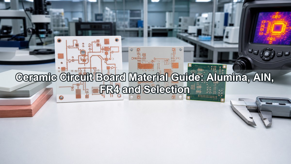
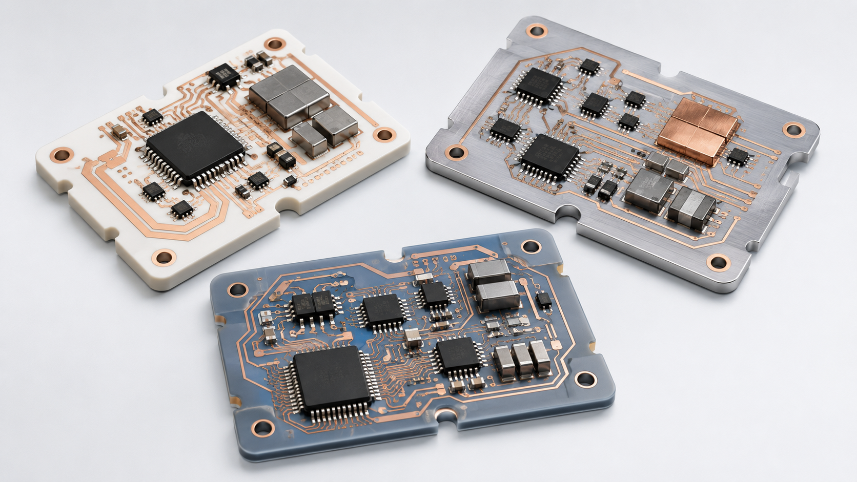
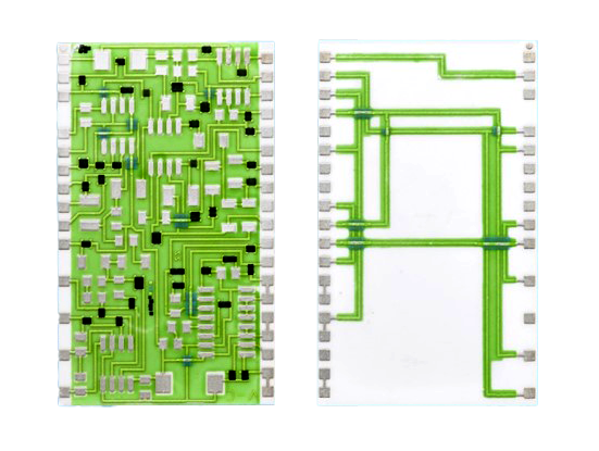
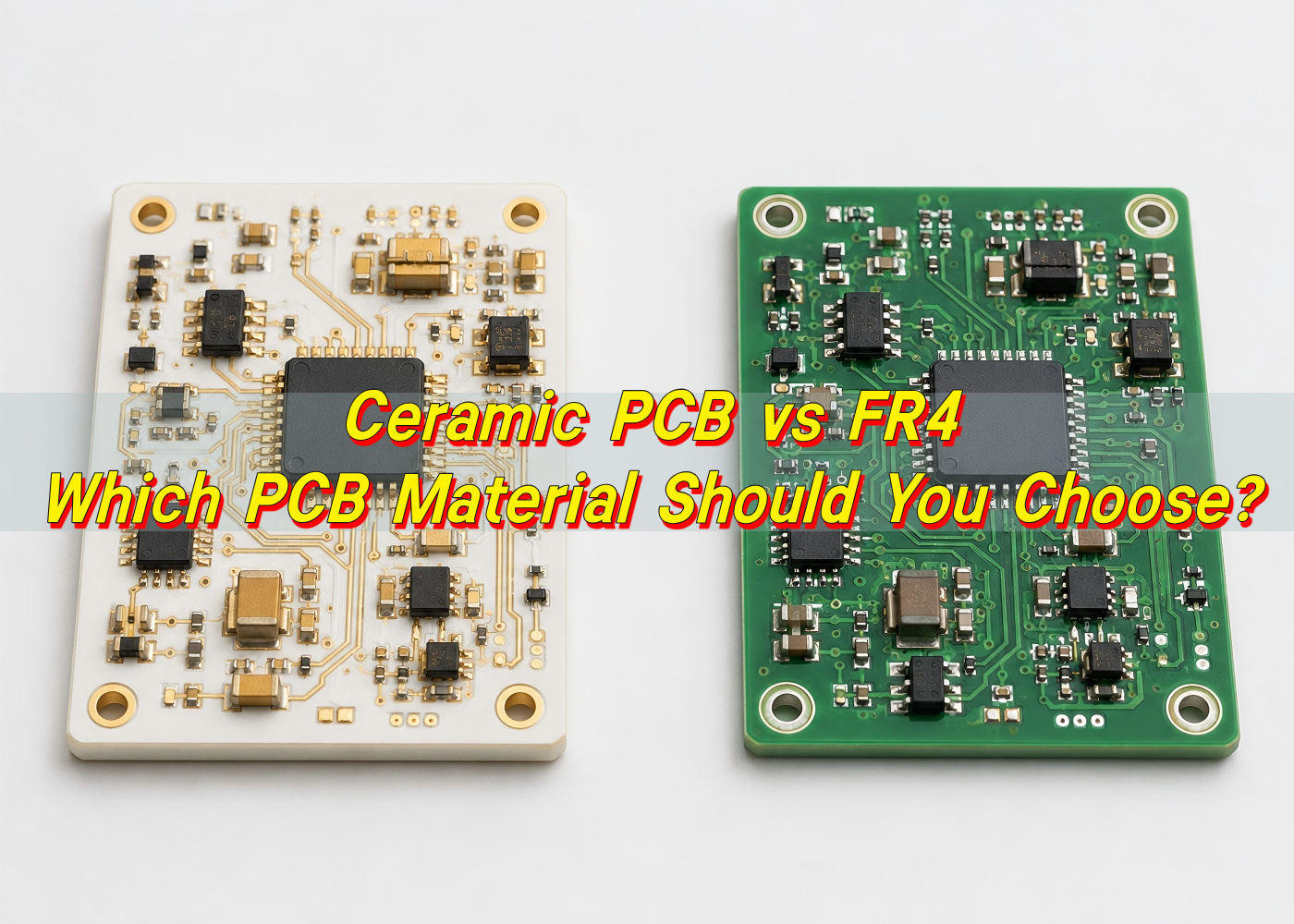
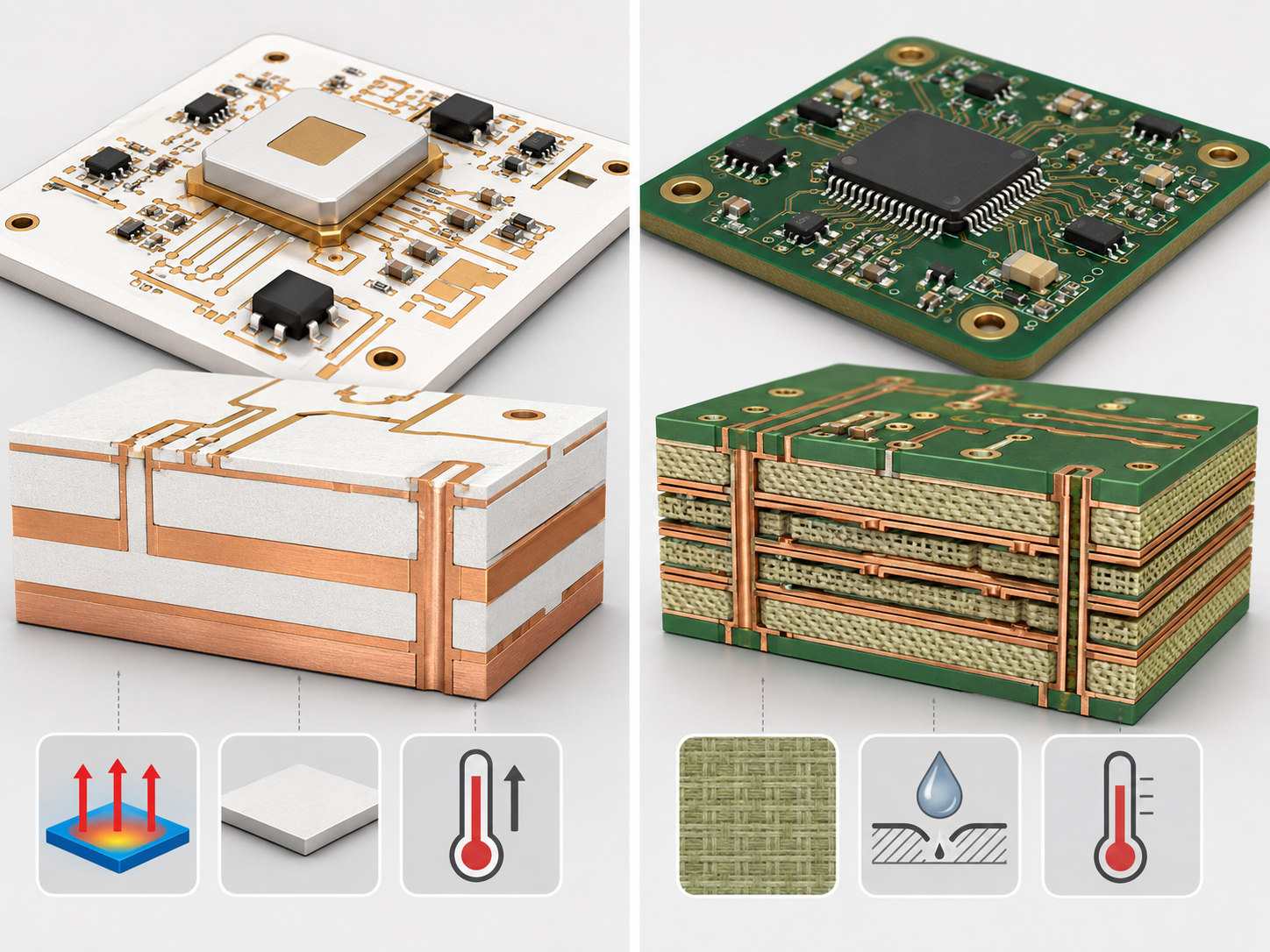
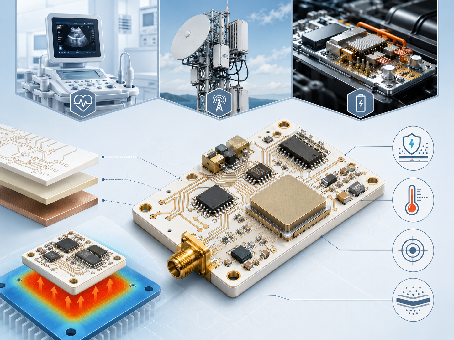
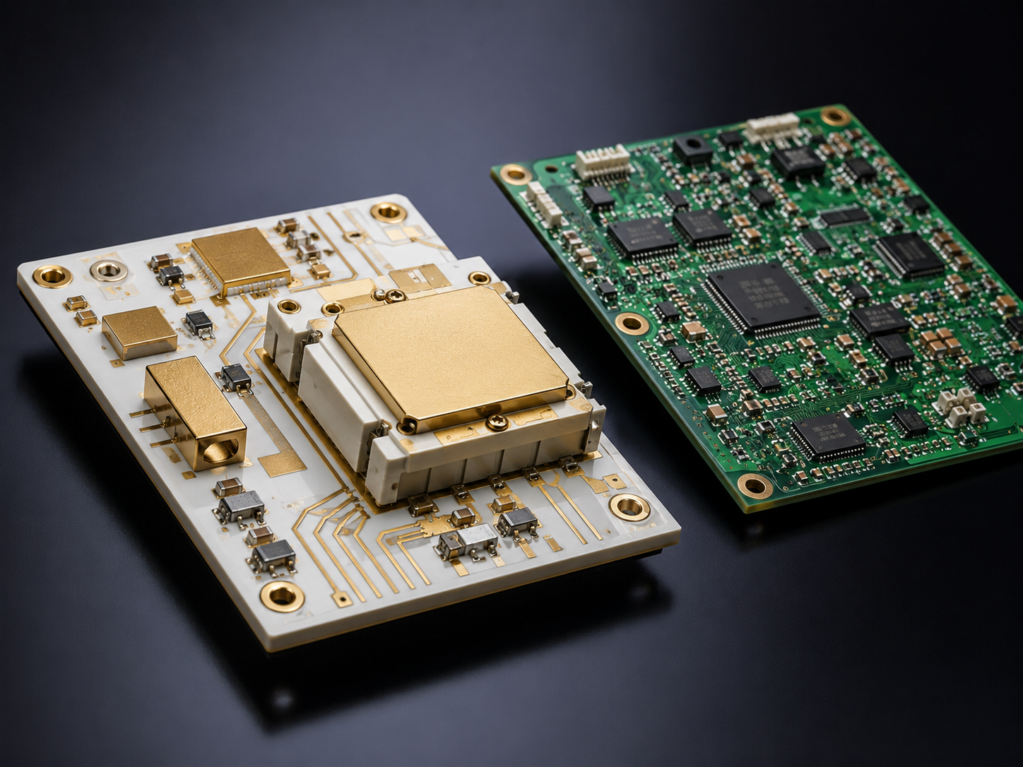
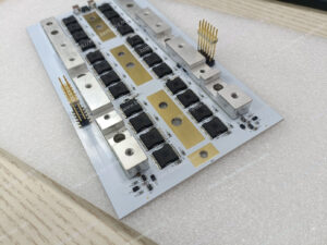
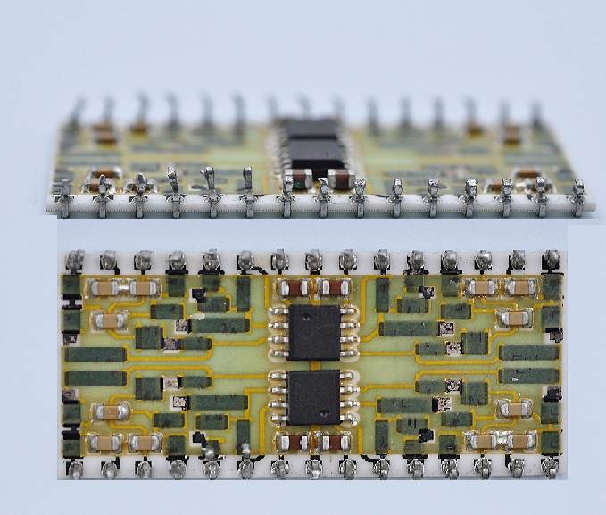
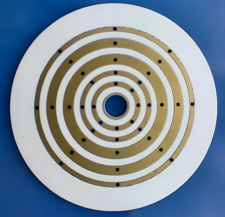
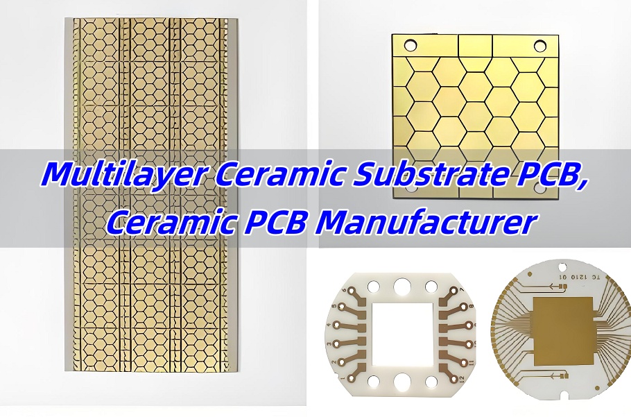
Ceramic circuit board material selection decides how a PCB handles heat, voltage, insulation, dimensional stability, assembly stress and long-term reliability. The practical choice is usually not simply ceramic versus non-ceramic; it is whether alumina, aluminum nitride, FR4, metal core PCB or another substrate can meet the electrical, thermal, mechanical and cost targets of the design.
This guide focuses on the material decisions that affect real PCB and PCBA projects: when ceramic is necessary, when FR4 PCB is still the better option, how alumina PCB differs from aluminum nitride PCB, and what information should be prepared before asking a ceramic PCB manufacturer for a quote.
What Is Ceramic Circuit Board Material?
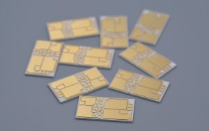
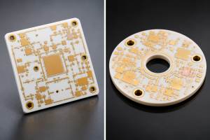
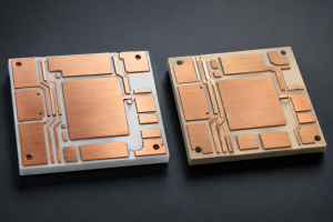
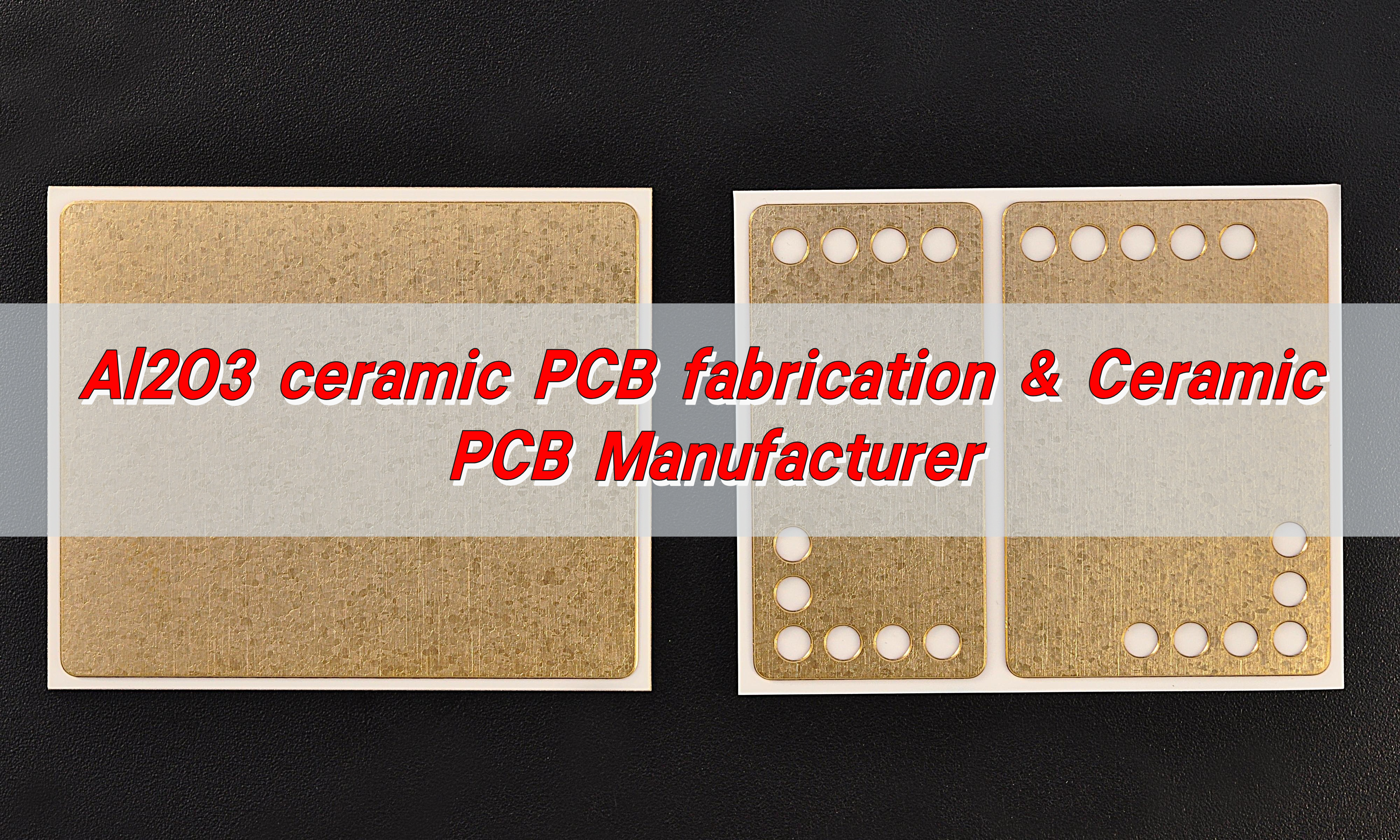
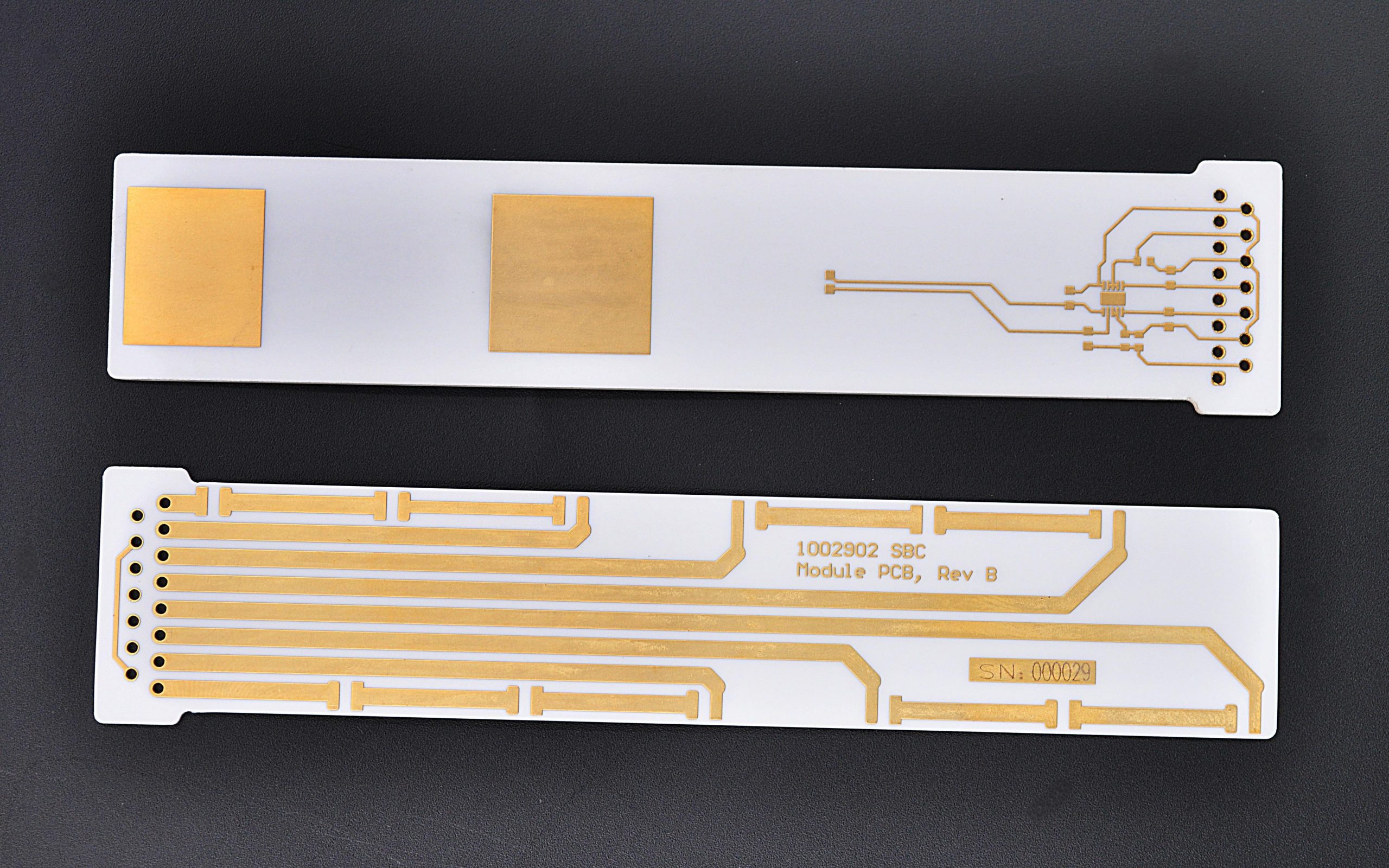
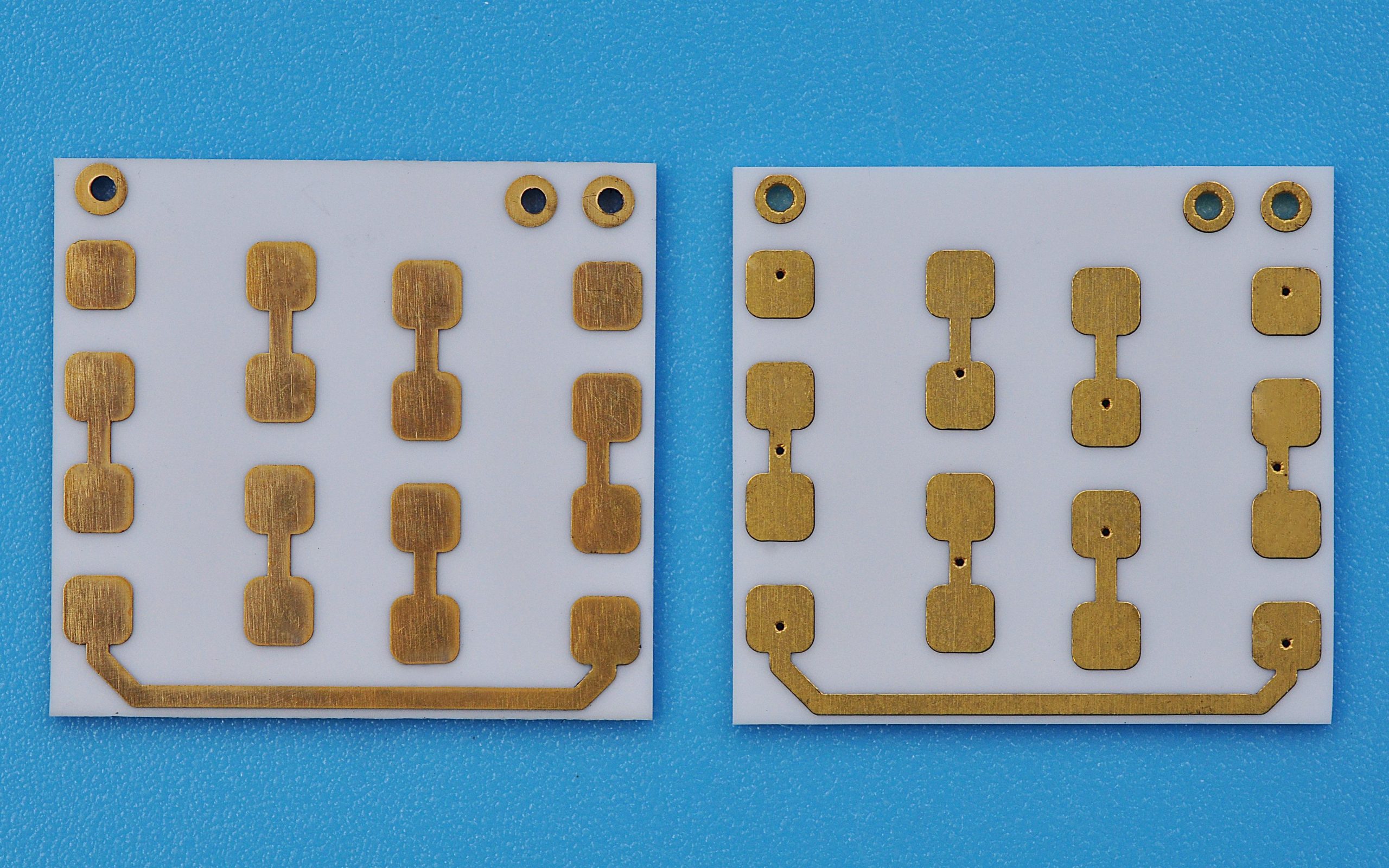
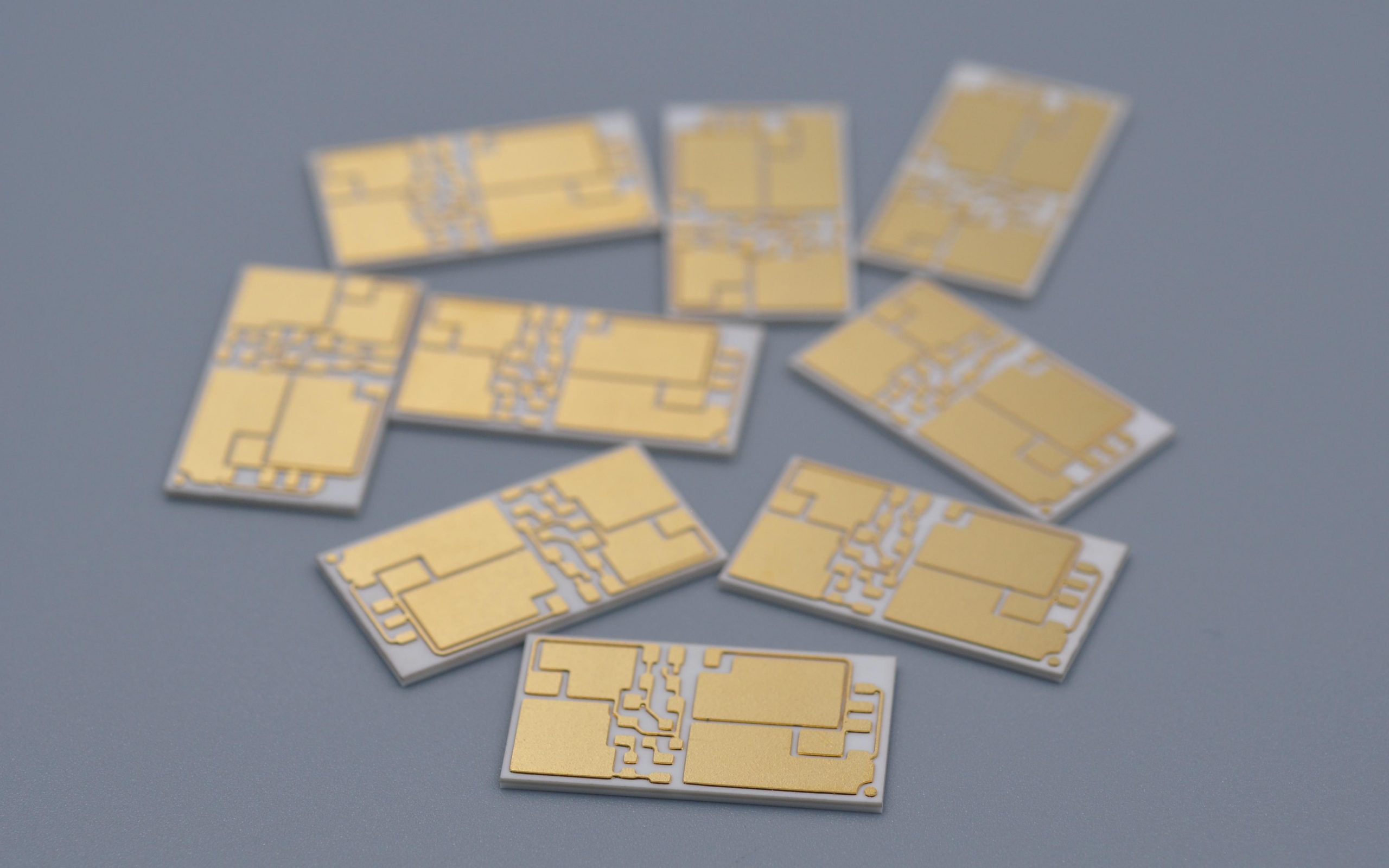
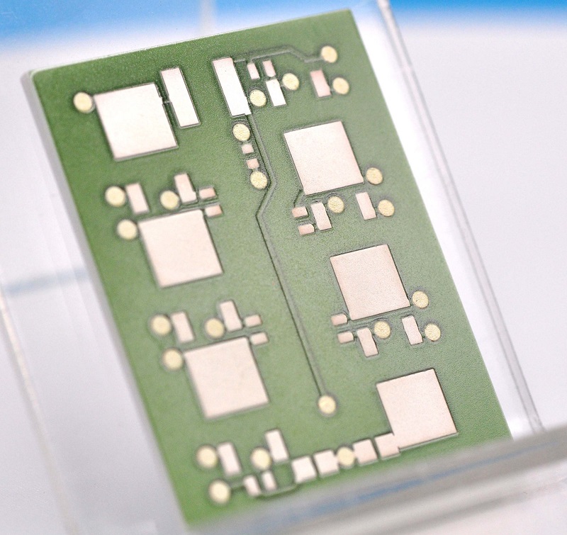
Ceramic circuit board material is an inorganic insulating substrate used as the base for copper circuitry. Common choices include alumina (Al2O3), aluminum nitride (AlN), beryllium oxide (BeO), silicon nitride (Si3N4), LTCC and HTCC materials. In a finished ceramic PCB, the ceramic base supports copper traces while providing electrical insulation and heat transfer.
Compared with organic laminates, ceramic substrates are selected for higher thermal conductivity, low moisture absorption, high-temperature stability, dimensional stability and good dielectric strength. These strengths are useful in LED modules, power devices, RF circuits, sensors, laser modules, semiconductor packaging and automotive electronics.
Why Use Ceramic PCB Instead of Standard FR4?
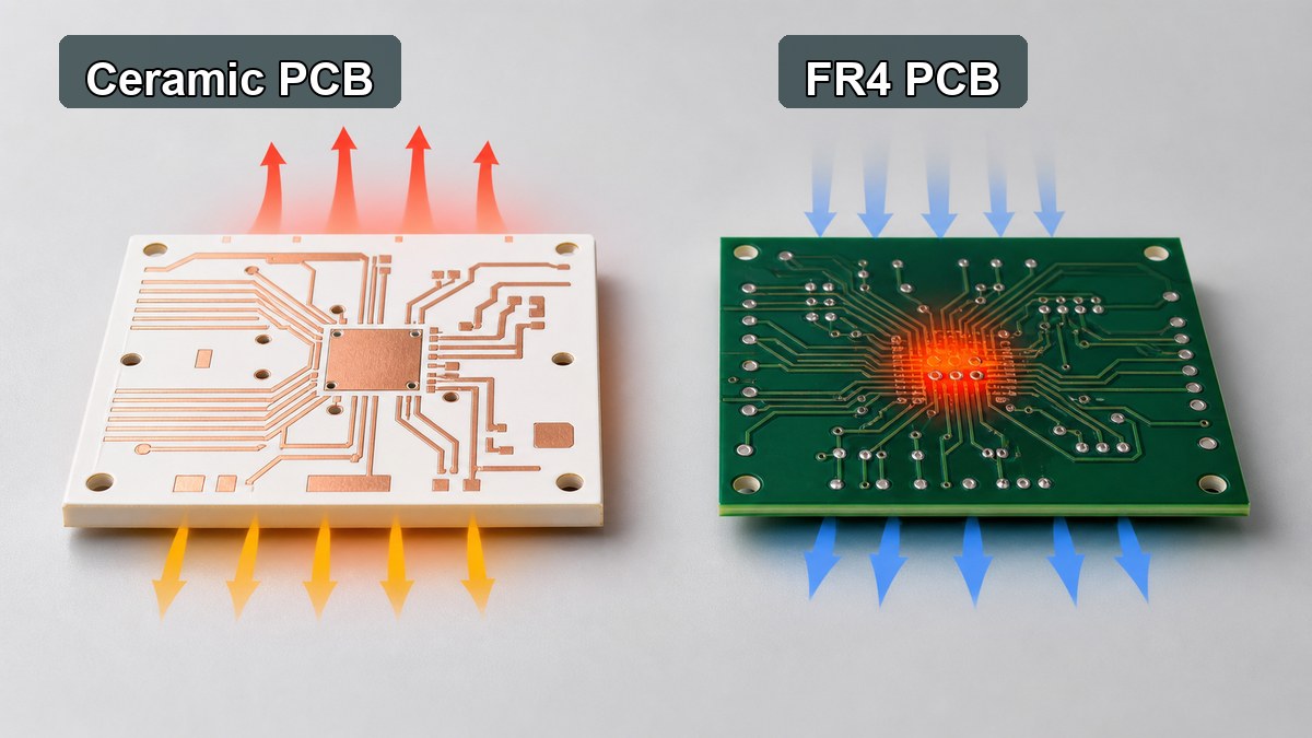
Use ceramic PCB instead of standard FR4 when the board must transfer heat through an electrically insulating substrate or operate in an environment where organic laminate properties are no longer enough. FR4 is economical, easy to process and flexible for multilayer routing, but ceramic provides a stronger platform for heat, voltage, stability and temperature resistance.
The decision should start from the stress in the design. If the circuit only needs standard digital routing, moderate current and normal operating temperature, FR4 is usually the practical first option. If the design concentrates heat under power devices, requires stable insulation at elevated temperature, or needs a compact high-power structure, ceramic PCB becomes worth reviewing.
Selection Factor
FR4 PCB
Ceramic PCB
Base material
Glass fiber reinforced epoxy laminate
Alumina, AlN, BeO, Si3N4, LTCC or HTCC ceramic
Thermal path
Limited through-thickness heat transfer
Better heat transfer through an insulating base
Routing flexibility
Excellent for multilayer signal routing
Usually simpler layer structures, depending on process
Temperature stability
Suitable for standard electronics and high-Tg options
Better for high-temperature and high-reliability environments
Cost position
Lower cost and broad availability
Higher cost, justified by thermal or environmental requirements
Which Ceramic Circuit Board Materials Are Commonly Used?
The most common ceramic circuit board materials are alumina and aluminum nitride, with other ceramic systems used when the application has special thermal, RF, packaging or reliability needs. The material name should be connected to the circuit process, copper thickness, surface finish, assembly method and reliability target.
Material
Practical Strength
Typical Use
Review Point
Alumina ceramic substrate
Balanced insulation, stability and cost
LED, sensors, power control, thick film and DPC ceramic circuits
Confirm purity, thickness, copper process and thermal target.
Aluminum nitride PCB
Higher thermal conductivity than alumina
High heat flux modules, laser drivers, power electronics and compact LED systems
Confirm handling, cost and metallization compatibility.
BeO ceramic PCB
Very high thermal conductivity
Special thermal applications where permitted
Confirm safety, compliance and supplier capability before selection.
LTCC / HTCC
Multilayer ceramic packaging and high-reliability structures
RF modules, sensors, hermetic or compact electronic packages
Confirm design rules, firing shrinkage, conductor system and lead time.
When Is Alumina PCB the Practical Choice?
Alumina PCB is often the practical choice when the design needs ceramic insulation, dimensional stability and better thermal behavior than FR4, but does not require the higher thermal performance or cost of AlN. It is commonly used for ceramic circuits where cost control, mature processing and stable electrical insulation matter together.
For many projects, 96% alumina provides a balanced ceramic substrate for DPC, thick film and other ceramic PCB routes. Higher-purity alumina can be considered when tighter dielectric performance, surface quality or material consistency is important. The decision should be made with substrate thickness, copper thickness, line width, dielectric test requirement and assembly conditions in the same review.
When Should Aluminum Nitride PCB Be Selected?
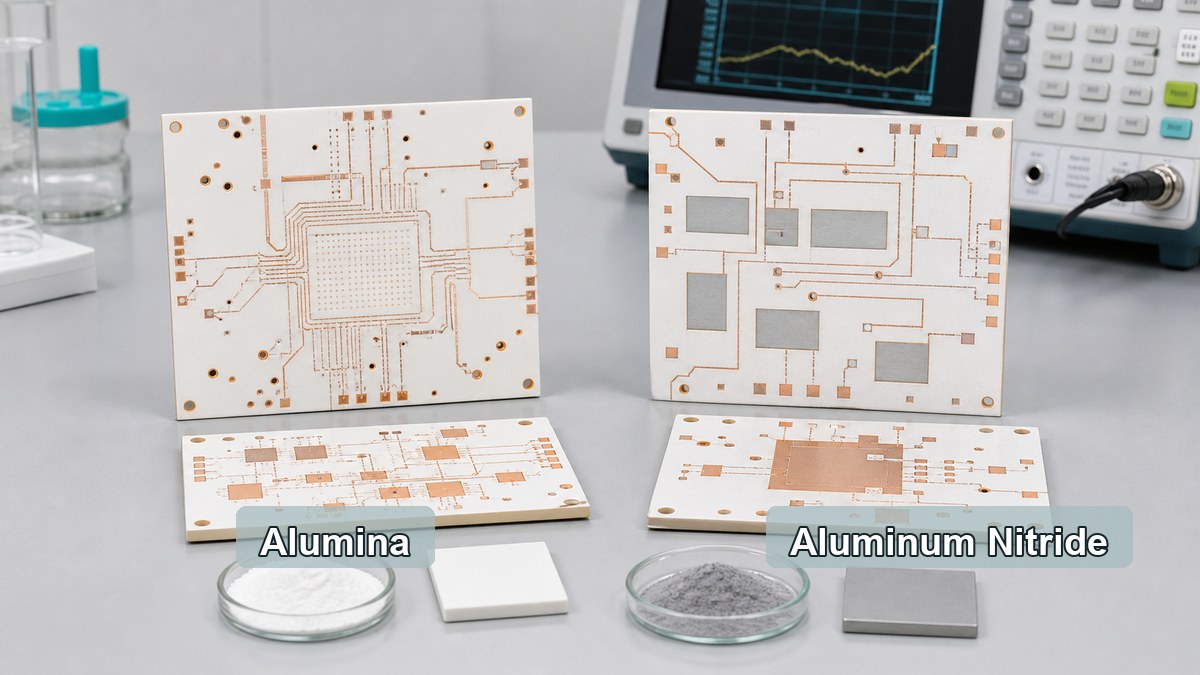
Aluminum nitride PCB should be selected when the limiting factor is heat spreading through the insulating substrate. AlN has much stronger thermal conductivity than alumina, so it is useful in compact power modules, high-power LED systems, laser modules, RF power circuits and applications where the heat source is small and concentrated.
AlN is not automatically the best material for every ceramic PCB. It usually costs more than alumina and requires careful handling and process control. It should be reviewed when thermal simulation, junction temperature, power density or module size shows that alumina cannot provide enough thermal margin.
How Do Ceramic Circuit Boards Compare With Metal Core PCB?
Ceramic circuit boards and metal core PCBs solve heat problems in different ways. A metal core PCB uses a metal base, usually aluminum or copper, with an insulating dielectric layer between the copper circuit and the metal. A ceramic PCB uses the ceramic itself as the electrically insulating and heat-conducting base.
Metal core PCB is often effective for LED lighting, power supplies and thermal spreading where the dielectric layer can meet the voltage and thermal requirements. Ceramic PCB becomes more relevant when the insulation layer must also be highly thermally conductive, dimensionally stable, low moisture absorption or suitable for elevated-temperature operation.
Which Manufacturing Processes Affect Ceramic PCB Material Selection?
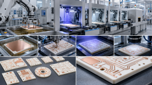
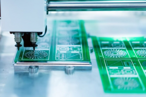
The manufacturing process affects ceramic PCB material selection because the same substrate can behave differently in thick film, thin film, DPC, DCB or other ceramic circuit routes. The process determines achievable line width, copper thickness, adhesion, surface finish, layer count, vias, cost and lead time.
Thick film ceramic PCB: suitable for printed conductor and resistor systems, commonly used on alumina.
Thin film ceramic PCB: useful for fine features, tight tolerances and high-frequency or precision circuits.
DPC ceramic PCB: supports plated copper features and is often used for LED, sensor and compact power applications.
DCB / DBC ceramic PCB: supports bonded copper on ceramic for higher-current power structures.
LTCC / HTCC: used when multilayer ceramic integration, compact packaging or high-temperature firing processes are needed.
EBest Circuit (Best Technology) supports ceramic PCB routes including thick film ceramic PCB, thin film ceramic PCB, DCB ceramic PCB, alumina ceramic PCB and AlN ceramic PCB, subject to material, dimensions, copper design and engineering review.
What Applications Need Ceramic Circuit Board Material?
Ceramic circuit board material is most useful when the application combines heat, electrical insulation, compact size or environmental stress. It is not limited to one industry, but it is most common where ordinary organic laminates would create thermal, dielectric or reliability limits.
High-power LED modules and optical devices
Laser diode and laser driver circuits
Power semiconductor modules and gate driver substrates
RF and microwave ceramic circuits
Automotive sensors and power electronics
Medical electronics and high-reliability instruments
Industrial controls exposed to heat or electrical stress
What Should Be Checked Before Requesting a Ceramic PCB Quote?
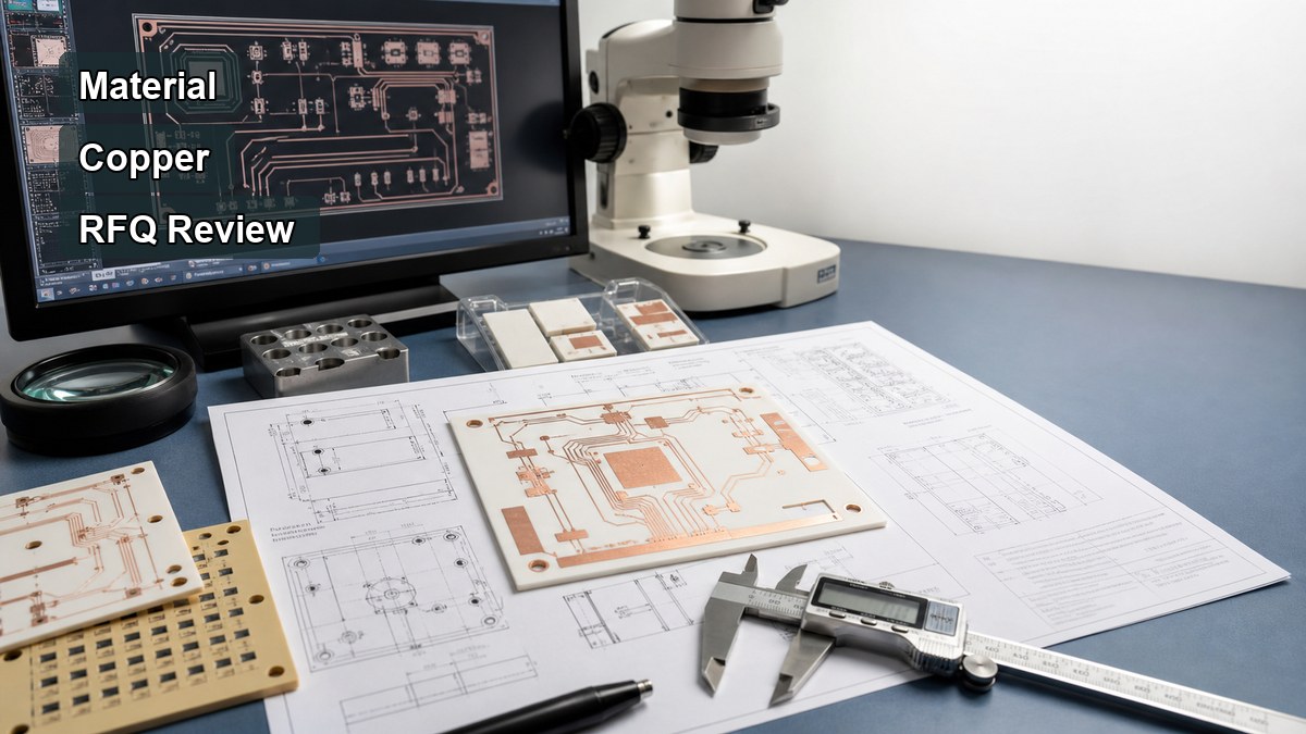
A ceramic PCB quote should include more than the material name. The RFQ should define the complete substrate and circuit structure so the manufacturer can review feasibility, cost and reliability before production.
Ceramic material: alumina, AlN, BeO, LTCC, HTCC or open for recommendation
Substrate thickness, copper thickness and finished board size
Line width, line spacing, hole size, vias and edge clearance
Process route: thick film, thin film, DPC, DCB or another ceramic process
Surface finish and soldering or wire bonding requirement
Operating temperature, voltage, current and thermal load
Assembly method, component type, solder profile and inspection needs
Prototype quantity, annual volume and target lead time
For a first build, a PCB prototype is usually the most practical way to validate material choice, circuit layout, assembly behavior and thermal assumptions before committing to volume production.
How Should You Choose a Ceramic PCB Manufacturer?
A ceramic PCB manufacturer should be evaluated by material capability, process match, engineering communication, inspection methods and willingness to review trade-offs before quotation. A supplier that only accepts a material name without checking drawings may miss important limits in copper geometry, substrate thickness, thermal stress or assembly compatibility.
EBest Circuit (Best Technology) can review ceramic PCB drawings together with FR4 PCB, MCPCB and PCB assembly requirements when the project includes mixed technologies. This is useful when the final product uses a ceramic circuit for the high-heat section and conventional PCBA for control, sensing or communication circuits.
FAQ About Ceramic Circuit Board Material?
1. Is ceramic PCB always better than FR4?
No. Ceramic PCB is better when the project needs ceramic-specific thermal, dielectric or temperature performance. FR4 is usually better for cost-sensitive multilayer routing, standard digital circuits and general electronics.
2. Is alumina PCB the same as aluminum nitride PCB?
No. Alumina PCB and aluminum nitride PCB are different ceramic substrate options. Alumina is often more cost-effective, while aluminum nitride is selected when higher thermal conductivity is needed.
3. Can ceramic circuit boards be assembled like standard PCBs?
Some assembly steps are similar, but ceramic boards need attention to solder profile, component stress, handling, surface finish and thermal expansion behavior. Assembly review should happen before prototype production.
4. What files are needed for a ceramic PCB quote?
Gerber files, drill files, board drawing, stack details, material requirement, copper thickness, surface finish, quantity, assembly notes and thermal or electrical requirements are normally needed for a useful quotation.
5. Should circuit board cement or circuit board clay be used as article keywords?
No. Those terms usually do not match ceramic PCB material selection intent. They should not guide the article structure unless a specific repair, adhesive or educational material topic is being written separately.
Conclusion
Ceramic circuit board material should be selected only after the thermal path, voltage requirement, substrate thickness, copper design, assembly method and cost target are clear. Alumina PCB is often the balanced ceramic option, aluminum nitride PCB is stronger for high heat flux, and FR4 remains the practical choice for many standard circuits.
If you are comparing ceramic PCB, FR4 PCB, metal core PCB or PCBA options, EBest Circuit (Best Technology) can review your drawings, material requirements and quotation details. Send your files or questions to sales@bestpcbs.com or contact EBest Circuit.
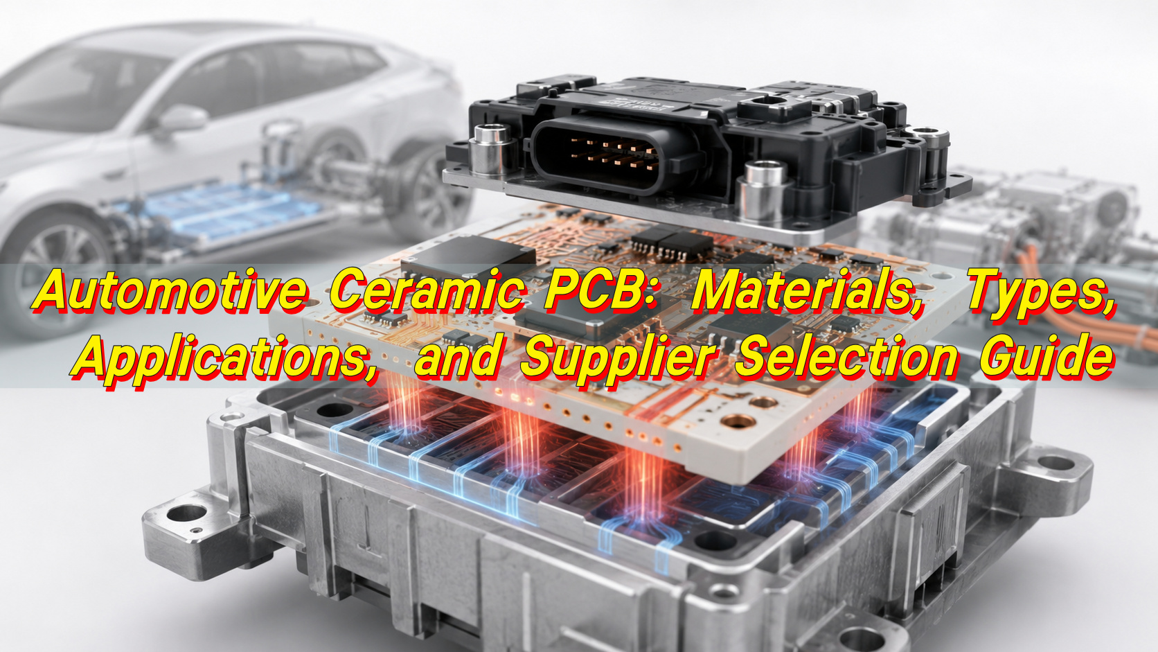
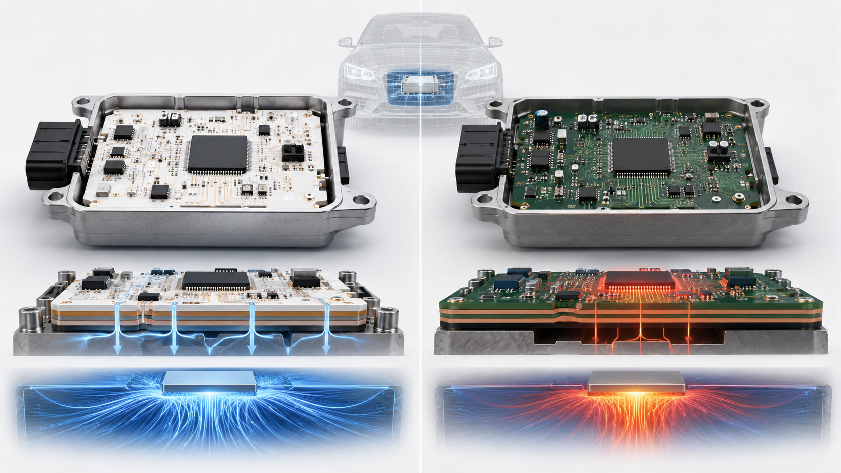
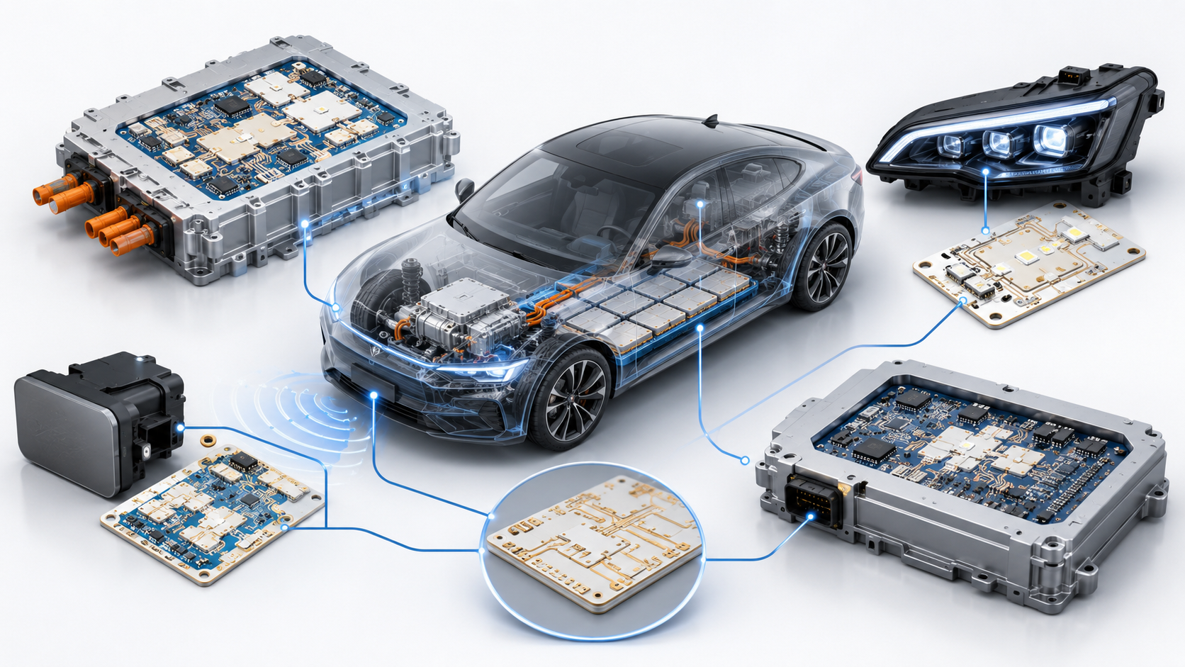
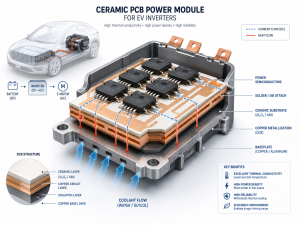
Automotive ceramic PCB technology is used when a vehicle electronic module needs stronger heat dissipation, better insulation, lower thermal expansion, and more stable performance than standard FR4 can provide. In electric vehicles, ADAS systems, LED headlights, battery control units, power modules, sensors, and high-current automotive PCB components, the circuit board is no longer just a connection carrier. It becomes part of the thermal path, electrical insulation system, and long-term reliability structure.
What Is an Automotive Ceramic PCB?
An automotive ceramic PCB is a printed circuit board that uses a ceramic substrate instead of conventional fiberglass-reinforced epoxy laminate. Common substrate materials include alumina, aluminum nitride, and silicon nitride. Copper circuitry is formed on the ceramic surface through processes such as DPC, DBC, AMB, thick film, or thin film manufacturing.
In automotive electronics, ceramic PCB is mainly used in modules exposed to heat, high power density, voltage stress, or repeated temperature changes. Typical examples include LED headlight boards, EV power conversion modules, battery-related control circuits, motor drive substrates, sensor modules, ignition-related electronics, and compact power control units.
Unlike FR4 PCB, ceramic PCB does not rely on organic resin as the main insulation base. This gives it better dimensional stability at high temperature, stronger thermal conductivity, and a coefficient of thermal expansion closer to many semiconductor materials. That is why many automotive PCB manufacturers use ceramic substrates for mission-critical thermal designs.
Why Are Ceramic PCBs Important in Automotive Electronics?
Modern vehicles contain more electronics than ever. EV platforms, hybrid systems, radar modules, high-brightness lighting, power converters, inverters, charging systems, and smart control units all create heat. At the same time, automotive modules must survive vibration, humidity, temperature cycling, current load, and long service life expectations.
Ceramic PCB helps solve several common automotive design problems:
It moves heat away from power devices more efficiently.
It provides stable electrical insulation under high voltage.
It reduces thermal expansion mismatch between chips, copper, solder, and substrate.
It supports compact layouts where heat sinks and thick FR4 structures are not enough.
It improves reliability in modules that face repeated heating and cooling.
For buyers, this matters because thermal failure is often expensive. A board that works in a bench test may fail after months of real vehicle use if the substrate, copper thickness, solder joint, and thermal path were not designed together.
How Does an Automotive Ceramic PCB Work?
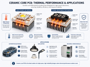
An automotive ceramic PCB works by combining electrical connection, insulation, and heat transfer in one structure. The ceramic substrate acts as an insulating but thermally conductive base. Copper traces or copper layers carry current and signals. Heat generated by power chips, LEDs, MOSFETs, IGBTs, resistors, or driver ICs is transferred through the copper and ceramic into the heat sink, housing, or cooling system.
The simplified thermal path is:
Heat Source
Transfer Layer
Main Function
LED, MOSFET, IGBT, driver IC, resistor
Copper circuit layer
Current path and first heat-spreading layer
Ceramic substrate
Alumina, AlN, or Si3N4
Electrical insulation and heat transfer
Interface material
Solder, sintered silver, thermal pad, or grease
Reduces thermal resistance
Heat sink or housing
Aluminum, copper, or module body
Final heat dissipation structure
The performance depends on the whole stack, not only the ceramic material. A high-thermal-conductivity substrate cannot fully solve the problem if the copper is too thin, the solder layer has voids, the board is warped, or the heat sink contact is poor.
Main Automotive Ceramic PCB Types
Different automotive applications need different ceramic PCB structures. The most common options are DPC, DBC, AMB, thick film, thin film, HTCC, and LTCC.
Type
Best Used For
Main Strength
Typical Limitation
DPC ceramic PCB
Fine circuits, sensors, LEDs, compact modules
Good circuit precision and plating control
Not ideal for very thick copper power modules
DBC ceramic PCB
Power electronics, EV modules, high-current circuits
Strong copper thickness and thermal path
Less suitable for very fine traces
AMB ceramic PCB
EV power modules, Si3N4 substrates, high thermal cycling
Strong bonding and mechanical reliability
Higher cost and stricter process control
Thick film ceramic PCB
Resistor networks, sensors, hybrid circuits
Stable functional films and mature process
Limited fine-line capability
Thin film ceramic PCB
RF, precision sensors, high-frequency modules
Excellent precision and signal stability
Higher cost for mass production
HTCC
Harsh-temperature and sealed packages
Strong high-temperature structure
Process cycle is longer
LTCC
RF, antenna, sensor, multilayer ceramic modules
Good integration and miniaturization
Material and process matching are critical
For automotive ceramic PCB selection, DBC and AMB are often considered for power modules, while DPC is more common for LED, sensor, and fine-circuit ceramic boards. Thick film and thin film ceramic PCB are chosen when functional resistive layers, precise metallization, or signal behavior matter.
Ceramic PCB Materials Used in Automotive Applications
Material choice is one of the most important decisions in ceramic PCB design. The substrate affects heat transfer, mechanical strength, cost, thermal expansion, process compatibility, and long-term reliability.
Material
Typical Thermal Conductivity
Typical Use in Automotive Electronics
Selection Note
Alumina ceramic
About 20–30 W/m·K
LED modules, sensors, moderate-power control boards
Cost-effective and widely used
Aluminum nitride
Often 170 W/m·K or higher
High-power LEDs, EV power modules, laser drivers, compact power boards
Strong thermal performance, higher material cost
Silicon nitride
Usually lower than AlN but mechanically strong
AMB power substrates, EV power cycling modules
Excellent strength and thermal shock resistance
Beryllium oxide
High thermal conductivity
Special high-performance uses
Limited by safety and processing concerns
Alumina is often the practical starting point when cost control matters and the heat load is moderate. Aluminum nitride is preferred when thermal resistance must be reduced in a small space. Silicon nitride is valuable when mechanical robustness, thermal cycling, and copper bonding strength are more important than maximum thermal conductivity alone.
A good ceramic PCB manufacturer should not recommend the most expensive ceramic by default. The better approach is to match the substrate with junction temperature targets, voltage requirements, copper thickness, mounting method, and production volume.
Key Features and Benefits of Automotive Ceramic PCB
Automotive ceramic PCB offers several clear advantages when used in the right place.
Benefit
Why It Matters in Vehicles
High thermal conductivity
Helps control LED brightness decay, MOSFET heating, and power module temperature
Electrical insulation
Supports compact high-voltage and high-current designs
Low thermal expansion
Reduces stress between chips, copper, solder, and substrate
High temperature resistance
Performs better than organic boards in hot zones
Good dimensional stability
Supports accurate assembly and stable module geometry
Strong corrosion resistance
Useful in sealed or harsh-environment electronics
Compact structure
Helps reduce module size in EV and smart vehicle systems
The biggest benefit is not only heat dissipation. It is reliability under combined stress. Automotive modules rarely face just one stress factor. They often face heat, vibration, current load, humidity, and assembly pressure at the same time. Ceramic PCB can provide a stronger base for these demanding conditions.
Limitations and Risks You Should Know Before Selection
Ceramic PCB is powerful, but it is not suitable for every automotive board. FR4 is still the better option for many low-power control circuits, infotainment boards, general signal boards, and cost-sensitive modules.
Common limitations include:
Higher material and manufacturing cost than FR4
Brittleness during handling, routing, assembly, and module mounting
Design restrictions for board size, panel utilization, and mechanical holes
Longer production cycle for special materials or custom copper thickness
Higher requirement for soldering profile, fixture design, and packaging protection
Potential copper delamination if material, process, or thermal cycling is poorly controlled
The main mistake is using ceramic PCB as a direct FR4 replacement without redesigning the mechanical and thermal structure. Ceramic boards need careful attention to edge clearance, mounting pressure, copper balance, warpage, solder voids, and thermal interface contact.
Ceramic PCB vs FR4 for Automotive Electronics
Ceramic PCB vs FR4 is one of the most common comparison topics for automotive engineers and buyers. The correct answer depends on the heat load, voltage level, reliability target, cost range, and application zone.
General control, communication, logic, low-power boards
Use ceramic PCB when heat, insulation, or thermal cycling is the core reliability issue. Use FR4 when the board mainly handles low-power signals, standard control logic, or cost-sensitive assembly. In many automotive products, both materials can appear in the same system. A power section may use ceramic PCB, while the control section remains FR4.
EV power electronics Ceramic substrates are used in inverters, DC-DC converters, onboard chargers, power modules, and current control circuits. These applications need strong insulation and heat transfer.
LED headlights and lighting modules High-power LED headlights generate concentrated heat. Ceramic PCB helps keep LED junction temperature under control and supports long-term brightness stability.
Battery management and high-voltage control Some battery-related circuits need insulation stability, heat resistance, and reliable current handling. Ceramic boards can support compact layouts near high-power zones.
ADAS sensors and radar-related modules Sensor modules may require stable dimensions, low signal loss, and thermal stability. Thin film or LTCC ceramic solutions may be considered in selected high-frequency or sensor packaging designs.
Engine and transmission control environments Near-engine electronics face heat and vibration. Ceramic PCB can be used where standard boards may struggle with temperature cycling.
Automotive power resistors and hybrid circuits Thick film ceramic PCB is useful for resistor networks, hybrid circuits, and compact modules requiring printed resistive elements.
Practical Automotive Case Examples
A useful way to understand ceramic PCB is to look at realistic engineering scenarios.
Case
Original Problem
Ceramic PCB Solution
Result
LED headlight module
FR4 board caused high LED temperature and faster lumen decay
Alumina or AlN ceramic PCB with optimized copper area
Better heat spreading and more stable lighting performance
EV power module
High current created hot spots and solder fatigue risk
DBC or AMB ceramic substrate with thick copper
Lower thermal resistance and stronger power cycling reliability
Sensor module
Signal drift appeared after repeated temperature exposure
Thin film or precision ceramic substrate
Improved dimensional and electrical stability
Compact DC-DC board
Limited space made metal heat sink design difficult
AlN ceramic PCB integrated into heat path
Higher power density in a smaller module
High-temperature hybrid circuit
Organic substrate could not support operating zone
Thick film ceramic circuit
More stable long-term operation
These cases show one important point: ceramic PCB is selected to solve a specific bottleneck. It should be introduced when the thermal path, insulation demand, or environmental stress makes standard PCB materials less suitable.
Design Guidelines for Automotive Ceramic PCB
A strong automotive ceramic PCB starts with design decisions made before manufacturing. Engineers should not treat ceramic as only a material upgrade. The layout, copper geometry, substrate thickness, component placement, and mechanical mounting all affect reliability.
Key design points include:
Place high-heat components close to the main thermal path.
Avoid sharp copper corners where stress can concentrate.
Keep copper distribution balanced to reduce warpage.
Reserve safe edge clearance because ceramic edges are more fragile than FR4.
Control hole placement and avoid unnecessary mechanical stress points.
Match copper thickness with current load and heat-spreading needs.
Review solder pad size carefully to control voiding and wetting.
Define voltage clearance based on working voltage and pollution environment.
Confirm mounting torque, screw position, and support structure early.
Use DFM review before prototype production.
For automotive projects, the drawing should clearly specify substrate material, copper thickness, board thickness, surface finish, tolerance, flatness, test requirements, and packaging method. Missing details can create serious problems when the project moves from sample development to batch production.
Manufacturing Process Considerations
Automotive ceramic PCB manufacturing requires tighter process control than standard FR4 PCB. The right process depends on the required copper thickness, line width, substrate type, and reliability target.
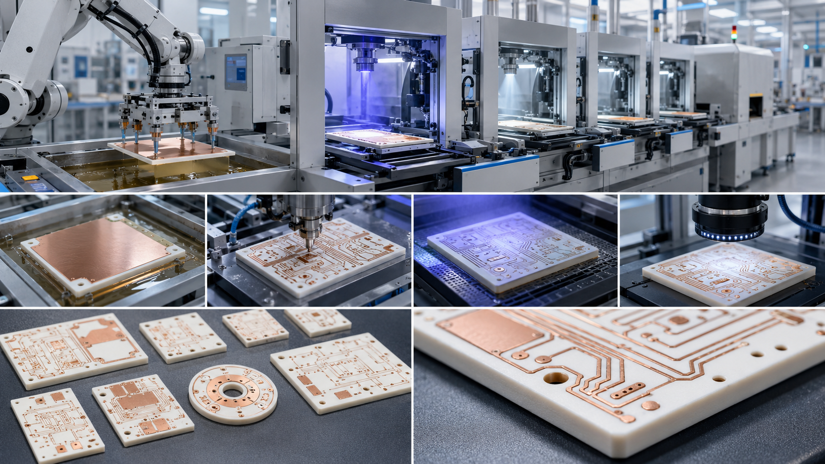
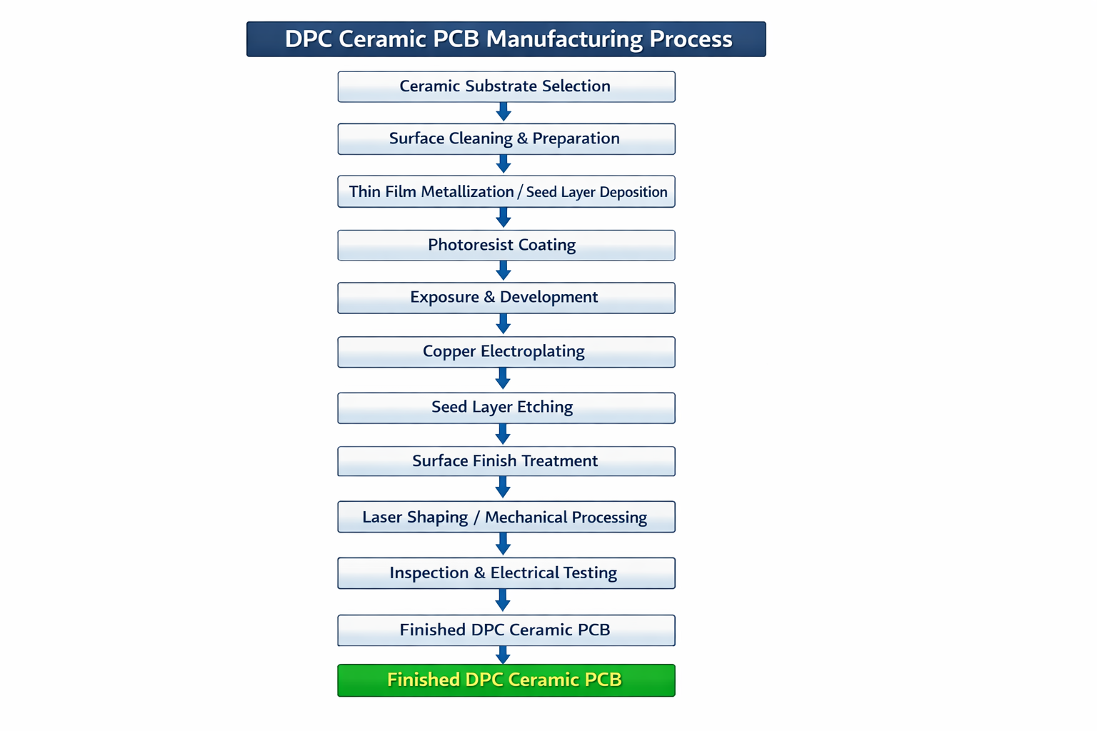
DPC process usually involves ceramic cleaning, seed layer deposition, imaging, copper plating, etching, solder mask or protective layer, surface finish, profiling, and final testing. It is suitable for fine circuits and medium copper thickness.
DBC process bonds copper directly to ceramic under high temperature. It is often used for power substrates with thicker copper and strong thermal transfer.
AMB process uses active brazing material to bond copper and ceramic, especially for silicon nitride substrates. It is suitable for high-reliability power modules and harsh thermal cycling conditions.
Thick film process prints conductive, resistive, or dielectric paste on ceramic and fires it at high temperature. It is useful for hybrid circuits and functional layers.
Thin film process uses vacuum deposition and photolithography for very precise circuits. It is common in high-frequency, sensor, and precision electronic modules.
Manufacturing quality depends on ceramic surface preparation, copper adhesion, plating uniformity, sintering or bonding control, etching accuracy, flatness, edge quality, and final cleaning. For automotive applications, process stability is often more important than a single impressive parameter.
Testing Methods and Quality Control
Automotive ceramic PCB quality control should cover electrical, thermal, mechanical, and visual reliability. A simple open-short test is not enough for critical vehicle modules.
Common testing and inspection items include:
Test or Inspection
Purpose
Electrical open-short test
Confirms basic circuit continuity and isolation
Hi-pot test
Checks insulation under high voltage
AOI
Detects line defects, scratches, contamination, and pattern issues
X-ray inspection
Reviews voids, bonding, or internal defects in selected assemblies
Thermal cycling test
Evaluates stress under repeated temperature changes
Copper adhesion test
Checks bonding strength between copper and ceramic
Warpage and flatness measurement
Supports stable assembly and heat sink contact
Microsection analysis
Reviews copper thickness, plating quality, and interface structure
Ionic contamination test
Helps reduce corrosion and leakage risk
Final visual inspection
Checks edge cracks, chipping, stains, and surface defects
For automotive PCB suppliers, quality control should also include lot traceability, material certificates, process records, inspection reports, and controlled packaging. This is especially important for OEM, ODM, and batch production projects where repeatability matters more than one successful prototype.
Common Failure Modes and Factory-Level Prevention
Automotive ceramic PCB failures usually come from the interaction of material, design, assembly, and operating stress.
Control torque, improve panel handling, add support structure
Copper delamination
Weak bonding, thermal shock, poor material match
Select proper DBC/AMB/DPC process and verify adhesion
Solder joint fatigue
CTE mismatch and repeated thermal cycling
Optimize pad design, solder profile, and component placement
Hot spots
Poor thermal path or insufficient copper area
Improve copper spreading, substrate selection, and heat sink contact
Insulation breakdown
Contamination, insufficient clearance, high voltage stress
Improve cleaning, spacing, coating, and hi-pot testing
Warpage
Unbalanced copper, process stress, thin substrate
Balance copper and control firing/bonding process
Surface contamination
Poor cleaning or packaging
Add cleanliness inspection and vacuum or dry packaging
A strong ceramic PCB manufacturer should be able to discuss these failure modes before production, not only after defects appear. For automotive projects, prevention is always cheaper than field failure analysis.
Cost Factors in Automotive Ceramic PCB
Automotive ceramic PCB cost is affected by material, board size, copper thickness, process type, tolerance, surface finish, test requirements, and order volume.
Main cost drivers include:
Ceramic material: AlN and Si3N4 usually cost more than alumina.
Process type: AMB and thin film are generally more expensive than basic alumina DPC.
Copper thickness: thicker copper increases material and processing difficulty.
Circuit precision: fine lines and tight spacing require stricter control.
Board size: larger ceramic panels are harder to process and protect.
Surface finish: ENIG, ENEPIG, silver, and other finishes affect cost.
Yield risk: complex structures and tight tolerances may reduce production yield.
Packaging: automotive ceramic boards need stronger protection during shipping.
The best cost strategy is not to choose the cheapest substrate. It is to define the real working conditions and avoid over-specification. For example, alumina may be enough for a moderate-power LED board, while AlN may be necessary for a compact high-power module. Using AlN where alumina is sufficient increases cost without adding meaningful value.
How to Choose a Ceramic PCB Manufacturer for Automotive Projects?
Choosing a ceramic PCB manufacturer is not only about unit price. Automotive projects need engineering support, process stability, documentation, and repeatable quality.
A qualified supplier should be able to support:
Alumina, aluminum nitride, and selected silicon nitride ceramic substrates
DPC, DBC, AMB, thick film, or other suitable manufacturing processes
Prototype development and batch production transfer
Material traceability and incoming inspection
Copper thickness verification and adhesion testing
Hi-pot, AOI, dimensional, and flatness inspection
Engineering DFM review before production
Controlled packaging for fragile ceramic substrates
Clear communication on tolerances, lead time, and process limits
OEM and ODM custom project support
Global shipping from a real China source factory without false local claims
For overseas buyers, especially in North America and Europe, the supplier should understand compliance documentation, automotive quality expectations, RoHS/REACH material control, and long-term repeat orders. For Southeast Asian and emerging markets, flexible MOQ, stable lead time, and cost-performance balance may be more important. In both cases, transparent engineering communication is more valuable than a low quotation with unclear process details.
RFQ Checklist Before Placing an Order
Before requesting a quotation, prepare a complete technical package. This helps the supplier give a more accurate price and reduces sample risk.
RFQ Item
Why It Matters
Gerber files
Defines circuit pattern
BOM and assembly drawing if PCBA is needed
Helps review component and soldering requirements
Substrate material
Determines thermal and mechanical performance
Ceramic thickness
Affects strength, insulation, and heat transfer
Copper thickness
Affects current capacity and heat spreading
Surface finish
Affects solderability, bonding, and storage life
Working voltage and current
Helps define clearance, insulation, and copper design
Operating temperature range
Supports thermal reliability review
Thermal target or power loss
Helps select alumina, AlN, or Si3N4
Quantity and forecast
Affects process planning and cost
Test requirements
Clarifies quality control level
Packaging requirement
Prevents ceramic damage during shipment
If your project is still in early development, share the application environment and expected power level first. A responsible ceramic PCB supplier can help narrow the material and process direction before the final drawing is frozen.
Frequently Asked Questions About Automotive Ceramic PCB
What is an automotive ceramic PCB used for? An automotive ceramic PCB is used in vehicle electronic modules that need strong heat dissipation, electrical insulation, and long-term reliability. Common applications include EV power modules, LED headlights, DC-DC converters, battery-related circuits, sensors, high-power control boards, and hybrid electronic modules.
Is ceramic PCB better than FR4 for automotive electronics? Ceramic PCB is better when the main challenge is heat, high voltage, thermal cycling, or compact power density. FR4 is still better for many low-power signal and control boards because it is lower cost, easier to process, and more flexible for multilayer routing.
Which ceramic material is best for automotive PCB? There is no single best material for every automotive project. Alumina is cost-effective for moderate heat. Aluminum nitride is better for high thermal conductivity. Silicon nitride is useful when mechanical strength and thermal shock resistance are critical, especially in demanding power modules.
What is the difference between DPC and DBC ceramic PCB? DPC ceramic PCB is better for fine circuits, plated copper control, and compact modules. DBC ceramic PCB is better for thicker copper and high-power thermal paths. For automotive power electronics, DBC is often considered when current and heat load are higher.
When should I choose AMB ceramic PCB? AMB ceramic PCB is often selected for high-reliability power modules, especially when silicon nitride substrates are used. It offers strong bonding performance and good thermal cycling resistance, making it suitable for EV power modules and harsh automotive environments.
Can ceramic PCB be used for automotive LED headlights? Yes. Ceramic PCB is widely used in high-power automotive LED lighting because it helps transfer heat away from LED chips. Better thermal control can support stable brightness, longer service life, and more compact headlight module design.
Why is automotive ceramic PCB more expensive than FR4? Ceramic substrates cost more than FR4 laminates, and the manufacturing process is more specialized. Cost also increases with AlN or Si3N4 material, thick copper, fine lines, tight tolerances, surface finish requirements, and automotive-level testing.
Does ceramic PCB crack easily? Ceramic PCB is more brittle than FR4, so it needs careful handling, proper packaging, controlled mounting force, and good fixture design. With correct mechanical design and production control, ceramic boards can perform reliably in demanding automotive applications.
What tests are important for automotive ceramic PCB? Important tests include open-short testing, hi-pot insulation testing, AOI, copper adhesion testing, flatness measurement, thermal cycling, dimensional inspection, and microsection analysis when needed. For high-reliability modules, test requirements should be confirmed before production.
Can ceramic PCB support high-current automotive components? Yes, especially when DBC or AMB structures with thicker copper are used. Current capability depends on copper thickness, trace width, substrate material, thermal path, operating temperature, and heat sink design. The board should be reviewed together with the full module structure.
How do I choose between alumina and aluminum nitride? Choose alumina when cost control matters and the heat load is moderate. Choose aluminum nitride when the design needs much better thermal conductivity in a compact space. The decision should be based on power loss, junction temperature target, board size, and total thermal resistance.
What information should I send to a ceramic PCB supplier? Send Gerber files, substrate material, copper thickness, ceramic thickness, surface finish, working voltage, current load, operating temperature, quantity, testing needs, and application details. If the design is not finalized, share the thermal and mechanical requirements first.
Can a China ceramic PCB manufacturer support global automotive projects? Yes, if the manufacturer has real ceramic PCB production capability, material traceability, engineering review, quality documentation, stable process control, and global shipping experience. Buyers should verify capabilities instead of relying only on price or generic supplier claims.
What is the biggest design mistake with automotive ceramic PCB? The biggest mistake is replacing FR4 with ceramic without redesigning the thermal and mechanical structure. Ceramic PCB requires proper copper balance, edge clearance, mounting support, soldering control, and heat sink contact. Material selection alone cannot guarantee reliability.
Conclusion:
Automotive ceramic PCB is not a universal replacement for FR4, but it is one of the most effective solutions for vehicle modules where heat, high voltage, compact power density, and thermal cycling are the main design challenges. Alumina offers a practical cost-performance balance. Aluminum nitride supports stronger heat dissipation. Silicon nitride and AMB structures are valuable for demanding power cycling environments.
For engineering selection, start from the application conditions: power loss, operating temperature, voltage, available space, mounting structure, reliability target, and expected production volume. For procurement, focus on process capability, quality control, testing support, traceability, and whether the supplier can transfer prototypes into stable batch production.
As a China source factory and global ceramic PCB manufacturer, EBest Circuit(Best Technology) supports custom ceramic PCB development, OEM manufacturing, ODM production, prototype builds, and batch production for automotive and industrial electronics projects. If you need technical support, material selection advice, cost evaluation, or a quotation for your automotive ceramic PCB project, please contact our engineering team at sales@bestpcbs.com.
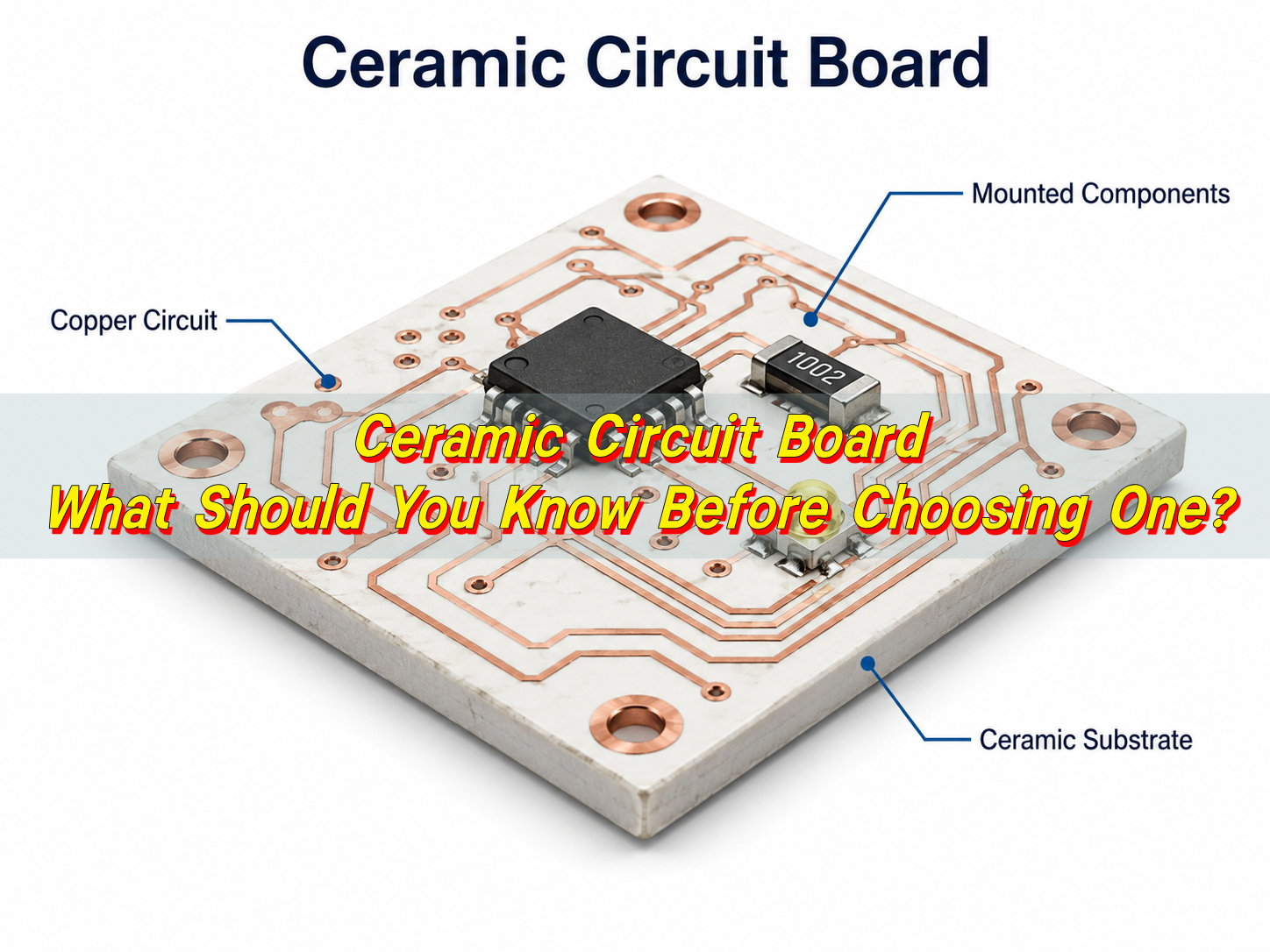
A ceramic circuit board is a printed circuit board that uses ceramic material as the insulating substrate instead of standard FR4 laminate. It supports copper circuits, carries electronic components, and helps manage heat in applications where ordinary PCB materials may not provide enough thermal or electrical performance.
Common ceramic circuit board materials include alumina, aluminum nitride, and silicon nitride. Each material has its own performance profile. Alumina is widely used because it offers a balanced combination of insulation, mechanical strength, thermal performance, and cost control. Aluminum nitride provides much higher thermal conductivity, making it suitable for high-power modules and compact thermal designs. Silicon nitride is often selected when mechanical toughness and thermal shock resistance are important.
A ceramic printed circuit board is often used in products that require excellent heat dissipation, high insulation strength, stable dimensions, and long service life. Typical applications include LED modules, power electronics, automotive electronics, medical devices, RF modules, laser equipment, industrial control systems, and aerospace electronics.
Compared with standard FR4, ceramic is not selected only for appearance or premium positioning. It is chosen because the material can support more demanding electrical and thermal conditions. In high-power circuits, heat can build up around components quickly. A ceramic pcb substrate helps move that heat away from the source more effectively, improving the operating stability of the final product.
For buyers and engineers, choosing a ceramic circuit board should start with the application requirements. Important factors include working temperature, power density, voltage level, copper thickness, circuit precision, assembly method, and production volume. EBest Circuit (Best Technology) supports ceramic PCB fabrication with material guidance, DFM review, process control, testing, and assembly support, helping customers move from prototype verification to production with fewer design risks.
How Does a Ceramic Circuit Board Work?
A ceramic circuit board works by combining an electrically insulating ceramic substrate with conductive copper circuits. The ceramic base provides mechanical support and insulation. The copper layer forms the electrical path for current and signals. When components generate heat, the ceramic substrate helps transfer that heat away from the component area and toward a heatsink, housing, or cooling structure.
This working principle is important in high-power electronics. For example, in an LED module, heat is generated near the LED chip. If the heat is not removed efficiently, brightness, color stability, and service life may be affected. A ceramic circuit board improves thermal transfer because ceramic materials conduct heat much better than standard FR4. This helps keep the operating temperature more stable.
The copper layer also plays a key role. It carries electrical current, spreads heat, and connects components. Depending on the board type, copper may be plated, bonded, printed, or brazed onto the ceramic surface. The bond between copper and ceramic must be strong enough to withstand soldering temperature, thermal expansion, electrical load, and repeated operating cycles.
A ceramic printed circuit board usually works through three functional parts:
Ceramic substrate: provides insulation, thermal transfer, and structural support.
Copper circuit layer: carries current, signals, and heat across the board.
Assembly layer: connects LEDs, chips, resistors, capacitors, sensors, connectors, or power devices.
The final performance depends on both material and design. Ceramic material gives the board strong thermal potential, but copper layout, substrate thickness, solder pad design, surface finish, and mounting method also affect the result. A ceramic board used in a power module, for example, needs a clear thermal path from the heat source to the cooling surface. A board used in RF equipment may need stable dimensions, tight tolerance, and controlled circuit geometry.
How Is a Ceramic Circuit Board Different from an FR4 PCB?
A ceramic circuit board and an FR4 PCB both provide electrical interconnection, but their base materials behave very differently. FR4 is made from glass fiber reinforced epoxy resin. It is widely used because it is cost-effective, easy to process, and suitable for many electronic products. Ceramic boards use inorganic ceramic substrates, which provide higher thermal conductivity, stronger insulation stability, and better dimensional control under heat.
The most important difference is thermal conductivity. Standard FR4 usually has thermal conductivity of about 0.3 W/m·K. Alumina ceramic is commonly around 20–30 W/m·K, while aluminum nitride can reach about 140–180 W/m·K, depending on material grade and production process.
FR4 remains a practical choice for many control boards, communication boards, consumer electronics, and general industrial products. Ceramic becomes more suitable when heat dissipation, high-voltage insulation, compact structure, or long-term reliability becomes a key design requirement.
Comparison Item
Ceramic Circuit Board
FR4 PCB
Base Material
Alumina, aluminum nitride, silicon nitride, or other ceramic material
Glass fiber reinforced epoxy laminate
Thermal Conductivity
About 20–180 W/m·K depending on material
About 0.3 W/m·K
Electrical Insulation
Excellent for high-voltage and high-power circuits
Good for standard electronic circuits
Heat Resistance
Strong performance in high-temperature applications
Suitable for normal PCB operating ranges
Dimensional Stability
Very stable under temperature changes
More affected by heat and moisture
Mechanical Behavior
Hard, stable, and brittle during processing
Easier to drill, route, and laminate
Cost Level
Higher material and process cost
More economical for general use
Typical Applications
LEDs, power modules, RF devices, medical, automotive, aerospace
Control boards, consumer electronics, communication modules, general PCBA
The right choice depends on the product environment. FR4 is suitable when the design has moderate power and enough space for thermal management. Ceramic is more suitable when the board itself must help handle heat, voltage, stability, or compact packaging. Cost should be reviewed together with the total product design. In some cases, ceramic can reduce the need for larger heatsinks or additional thermal structures.
Ceramic PCB vs FR4: Which One Should You Choose?
The choice between ceramic PCB and FR4 depends on power level, heat load, voltage requirement, product size, reliability target, and budget. FR4 is usually the preferred option for standard circuits because it offers good electrical performance, mature manufacturing, and lower cost. Ceramic circuit boards are better suited for applications that require stronger heat transfer, higher insulation strength, and stable operation under demanding conditions.
If the product is a low-power control board, sensor interface board, or general communication module, FR4 may be sufficient. If the product uses high-power LEDs, MOSFETs, IGBTs, laser diodes, RF power components, or compact power modules, ceramic should be evaluated early in the design stage.
Is the circuit mainly digital control or low-power signal processing?
FR4 PCB
Is high-voltage insulation a major requirement?
Ceramic circuit board
Is fast and economical multilayer production the main goal?
FR4 PCB
Does the product need compact size with better thermal transfer?
Ceramic circuit board
Is the application used in automotive, medical, aerospace, or industrial power systems?
Often ceramic, depending on design requirements
A practical material selection process should include thermal analysis, dielectric strength review, copper thickness selection, soldering method, mechanical mounting, and assembly requirements. Ceramic can provide strong performance, but it should match the actual design need. Over-specifying material may increase cost without adding meaningful value.
EBest Circuit (Best Technology) can review Gerber files, stackup information, power data, and application requirements to help determine whether ceramic, FR4, metal core PCB, or a hybrid structure is more suitable.
Why Are Ceramic Materials Used for Circuit Boards?
Ceramic materials are used for circuit boards because they combine electrical insulation, thermal conductivity, dimensional stability, and high-temperature resistance. This combination is valuable in electronic products that need to carry current while controlling heat.
In many circuits, the substrate must insulate copper traces and components from each other. At the same time, it may need to move heat away from active devices. Ceramic materials can perform both functions well. They are electrically insulating but thermally conductive, which makes them suitable for high-power and high-reliability applications.
The most common ceramic circuit board materials include alumina, aluminum nitride, and silicon nitride. Alumina is often used for LED modules, sensors, industrial electronics, and general ceramic PCB applications. Aluminum nitride is selected when thermal performance is the main concern. Silicon nitride is useful when the design needs higher mechanical strength and resistance to thermal shock.
Ceramic materials also have good chemical stability. They resist moisture, oxidation, and many harsh environments better than organic materials. Their low coefficient of thermal expansion helps reduce dimensional changes during heating and cooling. This is important for products exposed to repeated thermal cycles.
Main reasons ceramic materials are used include:
Better heat transfer for power components, LEDs, and compact modules.
Strong electrical insulation for high-voltage and high-density circuits.
High temperature capability for demanding operating environments.
Stable dimensions during thermal cycling and assembly.
Long-term reliability for industrial, automotive, medical, and aerospace applications.
Material selection should be based on real working conditions. Alumina is a balanced option for many projects. Aluminum nitride is preferred when heat dissipation is critical. Silicon nitride is considered when strength and thermal shock performance are priorities. A ceramic pcb manufacturer should help match the material to the application instead of recommending one substrate for every project.
What Are the Main Benefits of Ceramic Circuit Boards?
The main benefits of ceramic circuit boards are stronger thermal performance, excellent insulation, stable structure, and reliable operation in demanding environments. These benefits make ceramic suitable for products where heat, power density, and service life are important.
The most recognized benefit is heat dissipation. Heat affects component performance and product reliability. A ceramic pcb substrate provides a more efficient thermal path than FR4, helping components operate within a safer temperature range. This is useful for LEDs, power semiconductors, laser modules, and high-current circuits.
Ceramic circuit boards also provide excellent electrical insulation. This is important in power supplies, inverters, battery systems, medical devices, and high-voltage electronics. The material helps separate conductive layers and supports stable operation where insulation strength is a key requirement.
Another benefit is dimensional stability. Ceramic materials expand less than many organic PCB materials when temperature changes. This helps maintain circuit accuracy, component alignment, and solder joint stability. In precision electronics, RF devices, and high-reliability modules, this stability can improve consistency.
Benefit
Practical Value
High Thermal Conductivity
Helps remove heat from components more efficiently
Excellent Electrical Insulation
Supports high-voltage and high-power circuits
Strong Dimensional Stability
Helps maintain circuit accuracy under temperature changes
High Temperature Resistance
Suitable for heat-intensive applications
Compact Design Support
Helps reduce dependence on large thermal structures in some designs
Good Chemical Stability
Supports use in demanding environments
Long-Term Reliability
Suitable for products with extended operating life
Ceramic circuit boards are especially valuable when multiple requirements appear together. A board may need to handle high power, remain compact, provide insulation, and operate for many years. In these cases, ceramic can offer a strong technical foundation.
EBest Circuit (Best Technology) supports customers with ceramic PCB fabrication, PCB assembly, DFM review, material selection, testing, and production-quality support. This helps engineers select the right ceramic circuit board material and avoid issues related to copper adhesion, thermal bottlenecks, tolerance control, or assembly mismatch.
How Does a Ceramic Circuit Board Help with Heat Dissipation?
A ceramic circuit board helps with heat dissipation by transferring heat from components through the substrate and toward the cooling structure. In many electronic products, heat begins at the component junction, passes through the package, moves through the solder joint, enters the copper layer, and then travels into the board. If the substrate has poor thermal conductivity, heat may remain close to the component. Ceramic improves this path because it conducts heat much more effectively than standard FR4.
This advantage is important for high-power LEDs, power modules, RF power devices, laser diodes, and compact energy systems. These products often generate concentrated heat in small areas. A ceramic substrate helps spread and conduct that heat, reducing thermal stress around critical components.
The level of heat dissipation depends on the ceramic material. Alumina provides solid thermal performance for many applications. Aluminum nitride offers much higher thermal conductivity and is used when thermal control is a top priority. Copper thickness, copper area, substrate thickness, solder pad design, and mounting method also affect the final result.
Material
Typical Thermal Conductivity
Common Use
Standard FR4
About 0.3 W/m·K
General PCB circuits
Alumina Ceramic
About 20–30 W/m·K
LEDs, sensors, industrial electronics, power modules
Thermal design should consider the full heat path. The board material is only one part of the system. Component placement, copper layout, thermal pads, solder quality, thermal interface material, heatsink contact, and housing design all influence temperature control.
For example, a high-power LED module may use a ceramic substrate with a large copper pad under the LED. Heat moves from the LED package into the copper, through the ceramic, and then into the heatsink. If the design uses aluminum nitride, the heat transfer can be stronger, which helps compact lighting products and high-output modules.
How Are Ceramic Circuit Boards Manufactured?
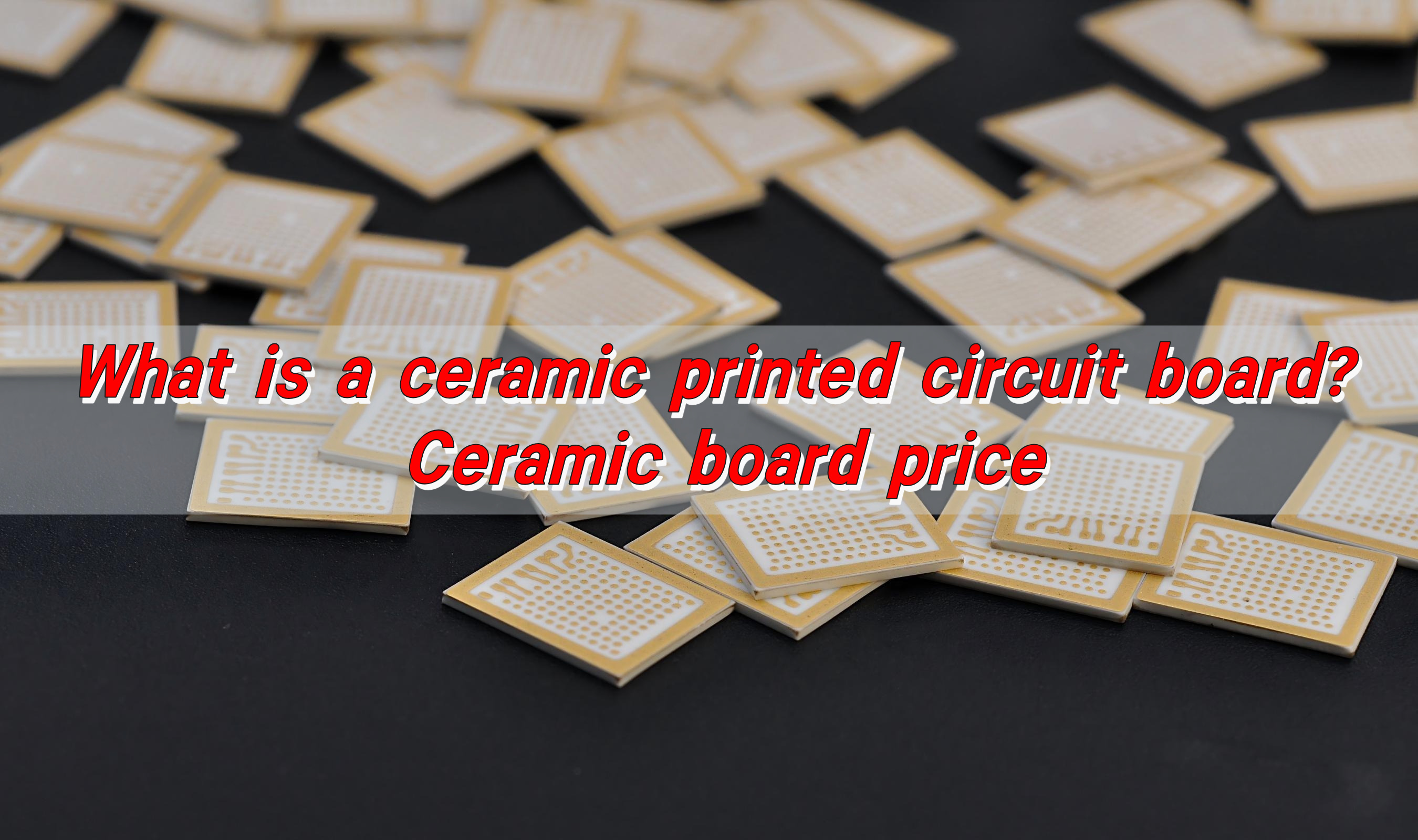
Ceramic circuit boards can be manufactured through several processes, including DPC, DBC, AMB, thick film, and thin film technology. The right process depends on copper thickness, circuit precision, thermal demand, bonding strength, production volume, and application type.
DPC, or Direct Plated Copper, is often used for fine circuits and compact ceramic PCB designs. Copper is deposited onto the ceramic substrate through metallization and plating. This process supports good pattern accuracy, smooth surface quality, and smaller circuit features. DPC is common in LED modules, sensors, RF devices, and precision electronic modules.
DBC, or Direct Bonded Copper, bonds copper foil directly to ceramic under high temperature. It supports thicker copper and higher current capacity. DBC ceramic printed circuit boards are widely used in power electronics, motor drives, inverters, automotive power systems, and industrial control equipment.
AMB, or Active Metal Brazing, uses active brazing material to bond copper and ceramic. It provides strong bonding strength and good thermal cycling performance. AMB is often selected for demanding power modules and high-reliability applications.
Thick film ceramic boards are made by printing conductive paste onto the ceramic surface and firing it at high temperature. This process is used for hybrid circuits, sensors, resistive circuits, and custom electronic modules. Thin film ceramic boards are used for high-precision circuits, RF designs, microwave products, and applications requiring stable electrical characteristics.
Process
Main Feature
Suitable Applications
DPC Ceramic PCB
Fine circuits and plated copper
LEDs, sensors, RF modules, compact electronics
DBC Ceramic PCB
Thick copper and high current capacity
Power modules, inverters, automotive electronics
AMB Ceramic PCB
Strong copper-to-ceramic bonding
High-reliability power electronics
Thick Film Ceramic PCB
Printed conductive paste and fired circuits
Hybrid circuits, sensors, custom modules
Thin Film Ceramic PCB
High precision and stable electrical behavior
RF, microwave, precision circuits
The manufacturing flow usually includes material selection, substrate preparation, cleaning, metallization, copper forming, imaging, etching, surface finishing, inspection, and testing. If the project includes assembly, SMT, chip bonding, wire bonding, or module assembly may follow.
Ceramic is harder and more brittle than FR4, so processing control is important. Cutting, drilling, laser processing, copper adhesion, surface finish, tolerance, and inspection must be managed carefully. A capable ceramic pcb manufacturer should understand both the material and the final product requirements.
EBest Circuit (Best Technology) provides ceramic PCB fabrication and PCBA support with DFM review, process evaluation, electrical testing, and production control. This helps customers reduce manufacturing risk and improve consistency from sample builds to volume production.
What Applications Use Ceramic Circuit Boards?
Ceramic circuit boards are used in applications that require reliable heat dissipation, high insulation strength, compact structure, and stable long-term performance. They are common in industries where the PCB must do more than provide basic electrical connection.
Common applications include:
High-power LED modules and lighting systems
Power semiconductor modules
Automotive lighting and electronic control units
Battery management and energy conversion systems
RF, microwave, and radar electronics
Medical sensors and diagnostic modules
Industrial control and automation equipment
Laser modules and optical electronics
Aerospace and high-reliability electronic systems
A ceramic circuit board is a strong choice when the product needs better heat dissipation, excellent insulation, stable dimensions, and dependable long-term performance. FR4 remains suitable for many standard PCB projects, while ceramic provides a higher-performance option for thermal, power, RF, medical, automotive, and industrial applications. Before choosing one, review the ceramic circuit board material, manufacturing process, copper thickness, thermal path, voltage requirement, tolerance, and assembly method together.
For ceramic printed circuit boards, PCB fabrication, PCBA assembly, and engineering support, EBest Circuit (Best Technology) can help evaluate your design and production needs. For project consultation or quotation, contact sales@bestpcbs.com
Choosing between ceramic PCB VS FR4 PCB is not only a material decision. It affects heat flow, electrical stability, board thickness, cost, lead time, assembly reliability, and long-term product performance. For many standard electronic products, FR4 is practical, proven, and cost-friendly. For high-power, high-temperature, high-frequency, or high-reliability designs, ceramic PCB can offer a stronger technical foundation.
At EBest Circuit (Best Technology), we usually recommend customers review the application first, not the material name first. Heat, voltage, frequency, size, reliability target, assembly method, and production volume should guide the decision. Once these points are clear, the comparison becomes much easier.
What Is a Ceramic PCB?
Ceramic PCB is a printed circuit board that uses a ceramic substrate instead of a traditional glass-reinforced epoxy base. The most common ceramic PCB materials include alumina, aluminum nitride, and sometimes silicon nitride. These materials are selected because they provide excellent thermal conductivity, strong electrical insulation, stable mechanical properties, and reliable performance under demanding conditions.
Ceramic PCBs are widely used in high-power LED modules, power electronics, RF circuits, semiconductor packaging, laser systems, medical equipment, sensor modules, and automotive electronics. These applications often need compact layouts and steady performance over long service life.
Common ceramic PCB manufacturing processes include thick film, thin film, direct plated copper, direct bonded copper, and active metal brazing. Each process has its own copper thickness range, bonding strength, line width capability, and cost level. For example, DPC ceramic PCBs are suitable for fine circuits and precision applications, while DBC and AMB ceramic substrates are often used for high-current and power module designs.
A ceramic PCB is often chosen when engineers need:
Better heat transfer from components to the substrate
Stable electrical insulation under high voltage or high temperature
Good dimensional stability for precision circuits
Long service life in harsh environments
Compact packaging for high-density power or RF designs
What Is an FR4 PCB?
An FR4 PCB is the most widely used type of printed circuit board in the electronics industry. FR4 refers to a glass fiber reinforced epoxy laminate. It acts as the insulating base material that supports copper circuits, solder mask, silkscreen, plated holes, and electronic components.
FR4 became popular because it offers a strong balance of performance, availability, manufacturability, and cost. It is easy to process, suitable for single-sided, double-sided, and multilayer boards, and compatible with most standard PCB fabrication and PCBA assembly workflows.
The key strength of FR4 is its versatility. It can support simple low-cost boards and advanced multilayer designs. Designers can select different Tg grades, copper weights, thicknesses, and finishes based on the application. High-Tg FR4 materials are also available for products that require better thermal resistance during soldering and operation.
FR4 PCB is commonly used for:
Control boards
Consumer electronics
Industrial automation circuits
Power supply control sections
Communication modules
IoT and smart devices
General LED driver boards
Automotive signal and control electronics
FR4 is a dependable choice when the board does not need extreme thermal conductivity from the base material. It can still handle many thermal designs through copper thickness, thermal vias, heat sinks, metal enclosures, and proper layout strategy. For many projects, this makes FR4 the most practical starting point.
Ceramic PCB vs FR4: What Is the Main Difference?
The main difference between ceramic PCB and FR4 PCB is the substrate material. Ceramic PCB uses a ceramic base with higher thermal conductivity, better dimensional stability, and stronger high-temperature performance. FR4 PCB uses glass fiber epoxy laminate, which is easier to manufacture, more flexible in multilayer design, and more cost-effective for general electronics.
A clear comparison helps explain the practical difference:
Comparison Item
Ceramic PCB
FR4 PCB
Base material
Alumina, aluminum nitride, silicon nitride, or other ceramic substrate
General electronics, control boards, digital circuits, cost-sensitive products
In everyday engineering terms, FR4 is the reliable workhorse, while ceramic PCB is the performance-focused material for tougher electrical and thermal requirements. A well-designed FR4 board can serve many products beautifully. A ceramic board becomes valuable when ordinary thermal paths or insulation strategies are no longer enough.
EBest Circuit often helps customers review this point during DFM evaluation. Sometimes a customer asks for ceramic PCB because they believe it is always better. After checking the power, thermal path, size, and cost target, FR4 may be enough.
How Does Ceramic PCB vs FR4 Compare in Thermal Conductivity?
Thermal conductivity is one of the most important reasons engineers compare ceramic PCB vs FR4. Ceramic substrates conduct heat much better than standard FR4 materials. This allows heat generated by LEDs, power semiconductors, RF devices, and high-current components to move more efficiently through the board.
Here is a practical comparison:
Material Type
Typical Thermal Conductivity Range
Practical Meaning
Standard FR4
Around 0.3 W/m·K
Suitable for general electronics with moderate heat
High-performance FR4 variants
Higher than standard FR4, but still limited compared with ceramics
Useful when better thermal resistance is needed without changing board family
Alumina ceramic PCB
Commonly around 20–30 W/m·K
Strong option for LED, sensors, power modules, and stable insulation
Aluminum nitride ceramic PCB
Commonly around 150–180 W/m·K or higher depending on grade
Excellent choice for high-power and high-heat-density applications
Silicon nitride ceramic PCB
Strong thermal and mechanical performance depending on grade
Suitable for advanced power modules and demanding environments
Thermal conductivity should be considered together with copper thickness, component package, solder layer, interface material, enclosure design, and airflow. A material with high conductivity can still perform poorly if the heat path is interrupted.
For LED lighting, ceramic PCB can help maintain lower junction temperature, which supports brightness stability and product life. For power electronics, it helps spread heat from MOSFETs, IGBTs, power diodes, and driver ICs. For RF circuits, stable temperature can also support more consistent electrical behavior.
In a practical design review, EBest Circuit usually checks heat source position, copper area, substrate thickness, via design, soldering process, and expected operating temperature. This prevents overpaying for materials in simple projects and helps select stronger substrates for products that require high thermal endurance.
Is Ceramic PCB Better Than FR4 for High-Power Applications?
Ceramic PCB is often better than FR4 for high-power applications because it provides a more efficient path for heat dissipation and offers excellent electrical insulation. High-power electronics create concentrated heat. If that heat stays near the component, it can affect output stability, solder joint reliability, and long-term product performance. Ceramic material helps move that heat away more effectively.
High-power applications where ceramic PCB is often considered include:
High-power LED modules
Laser diode modules
Power semiconductor substrates
EV power electronics
Industrial motor control modules
RF power amplifiers
Medical power devices
Aerospace and defense electronic modules
Compact DC-DC converters
High-voltage sensor and insulation circuits
Ceramic also performs well in applications where high voltage and heat appear together. Many ceramic substrates provide high dielectric strength, low moisture absorption, and stable insulation performance. These features are valuable for power modules that must operate safely and consistently over time.
FR4 remains widely used in power electronics as well. Many power supplies, inverters, chargers, and control boards use FR4 successfully. The key is that FR4 often needs additional thermal design support. This may include heavier copper, thermal vias, heat sinks, insulated metal substrates, or mechanical heat spreaders.
A useful way to decide is to review the heat path. If the main heat path depends on the PCB base material, ceramic is worth serious consideration. If the heat can be handled by copper, airflow, housing, or external heat sinks, FR4 may keep the project more cost-efficient.
When Should You Choose an FR4 PCB?
You should choose an FR4 PCB when your project needs a proven, economical, and flexible board material for general electronic functions. FR4 is especially suitable for signal routing, digital circuits, control boards, moderate-power applications, and products where cost control matters.
FR4 is a strong choice when your design has these characteristics:
The circuit is mainly digital, analog, control, or mixed-signal.
Heat generation is moderate and manageable through layout.
The project needs multilayer routing.
The budget requires efficient material cost.
The board needs common PCB processes such as plated through holes, impedance control, solder mask, and standard surface finish.
The product does not require extreme thermal conductivity from the substrate.
The design needs quick prototyping and easy scaling to production.
Here is a simple guide:
Project Requirement
Is FR4 a Good Choice?
Reason
Low to medium heat
Yes
Thermal needs can usually be handled by layout and copper design
Complex multilayer routing
Yes
FR4 multilayer fabrication is highly mature
Cost-sensitive production
Yes
Material and processing costs are efficient
General control electronics
Yes
FR4 supports stable, reliable circuit performance
Very high heat density
Depends
Additional thermal structures may be needed
High-power LED chip directly on board
Sometimes, but ceramic or metal core may perform better
Heat path becomes more critical
RF or microwave circuit
Depends
Special RF laminates or ceramic may be needed for tighter performance
When customers contact EBest Circuit for a new PCB project, FR4 is often the first material we evaluate because it is practical and widely suitable. If the design review shows that FR4 can meet the electrical, thermal, and mechanical requirements, it often provides the best cost-performance ratio.
When Should You Choose a Ceramic PCB?
You should choose a ceramic PCB when your design needs high thermal conductivity, strong insulation, compact heat management, high-frequency stability, or long-term reliability in demanding environments. Ceramic is especially valuable when performance stability matters more than material cost.
Ceramic PCB is a strong choice when the project has these needs:
High heat generation from LEDs, power chips, laser diodes, or RF devices
Compact board size with limited heat-spreading area
Strong electrical insulation under high voltage
Stable dielectric properties for high-frequency circuits
High reliability under thermal cycling
Low moisture absorption for sensitive applications
Good dimensional stability for precision assembly
Longer service life in industrial, medical, automotive, or aerospace products
The type of ceramic also matters. Alumina is popular because it balances performance and cost. Aluminum nitride is preferred when thermal conductivity is the main priority. Silicon nitride can support applications that need strong mechanical reliability and thermal performance. The circuit process also matters because DPC, DBC, AMB, thick film, and thin film ceramic boards serve different design goals.
A practical selection table can help:
Application Need
Suitable Ceramic Option
Why It Helps
Balanced thermal performance and cost
Alumina ceramic PCB
Reliable, widely used, stable, and cost-effective among ceramics
Very high thermal conductivity
Aluminum nitride ceramic PCB
Excellent heat transfer for dense power designs
High-current power module
DBC or AMB ceramic substrate
Strong copper bonding and power handling
Fine lines and precision circuits
DPC or thin-film ceramic PCB
Supports accurate circuit features
Harsh working environment
Alumina, AlN, or Si3N4 depending on design
Stable insulation and thermal performance
EBest Circuit (Best Technology) supports ceramic PCB material selection, DFM review, prototype production, and PCBA assembly support.
Ceramic vs PCB: Is Ceramic a PCB Material or a PCB Type?
Ceramic is a PCB material, and a ceramic PCB is a PCB type that uses ceramic as its substrate. Because PCB refers to the finished printed circuit board, while ceramic refers to the base material used to build a certain kind of PCB.
Think of PCB as the general product category. Inside that category, there are many material and structure options. FR4 PCB, ceramic PCB, aluminum PCB, copper core PCB, rigid-flex PCB, and high-frequency PCB are all different forms of printed circuit boards.
Here is a simple explanation:
Term
Meaning
Example
PCB
Printed circuit board used to connect and support components
Any electronic circuit board
FR4 PCB
PCB made with FR4 glass epoxy laminate
Control board, IoT board, industrial PCB
Ceramic PCB
PCB made with ceramic substrate
LED module, power substrate, RF module
Ceramic material
The substrate material used in ceramic PCB
Alumina, aluminum nitride, silicon nitride
PCB type
A board category based on structure or material
FR4, ceramic, metal core, rigid-flex
This distinction matters because the design process still follows PCB principles. Engineers still need Gerber files, copper layers, pads, spacing, surface finish, soldering requirements, and testing plans. The difference is that ceramic substrates require specific manufacturing methods and design rules. Hole processing, edge treatment, copper bonding, and metallization are different from standard FR4 fabrication.
Which PCB Material Is Better for LED, Power, and RF Applications?
The better PCB material depends on the application. For standard LED driver boards, FR4 may be suitable. For high-power LED modules where heat must move quickly from the light source, ceramic PCB or metal core PCB is often stronger. For power electronics, FR4 works well in control sections, while ceramic is preferred for dense power substrates. For RF circuits, material choice depends on frequency, dielectric stability, loss, and thermal needs.
For LED applications, ceramic PCB is attractive when the LED package produces high heat in a small area. Ceramic helps move heat away from the LED, which can support stable brightness and longer product life. FR4 can still be used in LED driver circuits, control boards, and lower-power lighting products.
For power applications, ceramic PCB performs well when the substrate must provide both insulation and heat transfer. This is common in power modules, high-voltage circuits, and compact converters. FR4 is still widely used for power supply control boards, gate driver boards, and general power electronics where the thermal design can be handled with copper, vias, and external heat sinks.
For RF applications, ceramic can provide stable dielectric properties and good thermal behavior, especially in compact or high-power RF modules. However, many RF PCBs also use specialized laminates such as Rogers materials, PTFE-based materials, or hydrocarbon ceramic-filled laminates.
Application
FR4 PCB
Ceramic PCB
Practical Recommendation
Low-power LED control board
Very suitable
Usually more than needed
FR4 is often practical
High-power LED module
Possible with careful thermal design
Very suitable
Ceramic or metal core PCB is often preferred
LED driver circuit
Very suitable
Selected for special thermal or insulation needs
FR4 is common
Power control board
Very suitable
Used when heat or insulation requirements are high
Choose based on heat density
Power module substrate
Limited in high heat density modules
Excellent
Ceramic is often stronger
RF low-frequency circuit
Suitable in many cases
Sometimes selected
FR4 may work if requirements are moderate
RF high-power or high-stability circuit
Depends on frequency and loss limits
Strong option
Ceramic or RF laminate may be better
Medical or aerospace high-reliability electronics
Suitable for many control circuits
Strong for thermal and stable substrate needs
Review reliability target carefully
The strongest material choice is usually application-specific. A product can also use more than one PCB type. For example, a power device may use an FR4 control board and a ceramic power substrate in the same assembly. EBest Circuit supports PCB fabrication and PCBA assembly for different material categories, including FR4, metal core PCB, ceramic PCB, RF PCB, and high-reliability boards.
Why Is Ceramic PCB More Expensive Than FR4 PCB?
Ceramic PCB is more expensive than FR4 PCB because the raw material, manufacturing process, metallization method, processing difficulty, and inspection requirements are more demanding. Ceramic substrates are harder and more brittle than FR4 laminates, so cutting, drilling, edge processing, copper bonding, and surface preparation require specialized control.
FR4 manufacturing is extremely mature and widely scaled. Material supply is broad, production lines are optimized, and standard processes can produce large volumes efficiently. Ceramic PCB production is more specialized. The factory must control substrate quality, metallization adhesion, copper thickness, dimensional tolerance, and thermal reliability with greater precision.
The cost difference comes from several main factors:
Cost Factor
Ceramic PCB
FR4 PCB
Raw material
Higher-cost ceramic substrates
Cost-efficient laminate materials
Processing method
Specialized laser, mechanical, metallization, or bonding processes
Mature drilling, plating, imaging, etching, and lamination
Copper bonding
Requires ceramic-compatible metallization or direct bonding
Standard copper-clad laminate process
Tooling and handling
More careful handling due to hardness and brittleness
More forgiving in standard fabrication
Yield control
Requires tight control for cracks, adhesion, and flatness
Highly standardized yield management
Application requirements
Often used in high-reliability products
Used across broad commercial and industrial products
Production scale
More specialized volumes
Large global production scale
Ceramic PCB cost also depends on material type. Alumina is usually more economical than aluminum nitride. Aluminum nitride offers much higher thermal conductivity, so it carries a higher material cost. The circuit process also changes pricing. DPC, DBC, AMB, thick film, and thin film processes have different cost structures.
Board size, copper thickness, line width, spacing, hole design, surface finish, tolerance, and inspection level also affect price. A simple alumina ceramic PCB may be relatively manageable in cost. A high-power AMB substrate or fine-line DPC ceramic board may require a higher budget because it delivers more advanced performance.
EBest Circuit (Best Technology) can support material selection, DFM review, PCB fabrication, component sourcing, PCBA assembly, and testing for projects moving from prototype to production. For engineers comparing FR4 vs ceramic, our team can review your Gerber files, stackup, power conditions, and reliability targets before recommending the most suitable board solution.
For project review or quotation support, contact EBest Circuit (Best Technology) at sales@bestpcbs.com.
Many electronic products now run hotter, smaller, and faster than before. That shift makes thermal design more important than ever. In many cases, standard FR4 works well. But when heat becomes harder to manage, ceramic substrates offer a more dependable path. With thermal conductivity that can reach 20 to 30 W/m·K for alumina and around 170 to 200 W/m·K for aluminum nitride, ceramic materials are often selected for power modules, LED lighting, RF products, and automotive electronics.
n this guide, you will learn what ceramic PCB design means, which materials are commonly used, how ceramic boards are manufactured, and how to choose between ceramic PCB and FR4 for different applications.
What Is Ceramic PCB Design?
Ceramic PCB design refers to the process of creating a printed circuit board on a ceramic substrate instead of a traditional FR4 base. In this type of board, the substrate does more than support the circuit. It also helps with heat transfer, insulation, and structural stability.
That is why ceramic PCB design is often used in applications where thermal control matters. A well-designed ceramic board can help reduce hot spots, support stable electrical performance, and improve product life in compact or high-power environments.
Typical application areas include:
High-power LED modules
Power semiconductor circuits
RF and microwave products
Automotive control systems
Medical and industrial electronics
Ceramic PCB Design
Why Choose Ceramic PCBs?
Ceramic PCBs are widely used because they combine heat dissipation and electrical insulation in one structure. This can make the full product design more efficient, especially in space-limited applications. Main advantages include:
Better heat dissipation than standard FR4
Stable performance under temperature cycling
Strong electrical insulation
Good dimensional stability
Suitable for compact and high-density layouts
For many engineers, the main attraction is thermal performance. Standard FR4 is usually around 0.3 W/m·K, which is enough for many general products. But for higher heat loads, ceramic substrates offer a clear improvement.
Why Choose Ceramic PCBs?
Common Materials Used in Ceramic PCB Design
Choosing the right ceramic pcb material is one of the first decisions in the design process. Different materials offer different thermal and mechanical properties.
Material
Thermal Conductivity
Cost Level
Typical Use
Al2O3
20–30 W/m·K
Lower
LED, sensors, control boards
AlN
170–200 W/m·K
Higher
Power modules, RF, high-heat products
Si3N4
70–90 W/m·K
Higher
High-reliability power electronics
BeO
Very high
High
Special industrial applications
In most commercial projects, the main decision is between Al2O3 and AlN.
Al2O3 vs AlN: Which One Is Suitable for Your Ceramic PCB Project?
Both materials are common in ceramic PCB design, but they fit different needs.
Property
Al2O3
AlN
Cost
More economical
Higher
Thermal Conductivity
Moderate
Very high
Availability
Broad
More specialized
Best For
General ceramic circuits
High-power thermal applications
A simple selection logic is:
Choose Al2O3 when you need a practical ceramic solution with balanced cost and performance.
Choose AlN when your board must remove heat faster or work in a tighter thermal environment.
Review the total thermal path before making the final decision.
If the product is compact, sealed, or power-dense, AlN often provides more design margin. If the thermal load is moderate, Al2O3 is often the more economical choice.
Ceramic PCB vs FR4 PCB: What’s the Difference?
The discussion around ceramic pcb vs fr4 is common because both materials serve important roles.
Aspect
Ceramic PCB
FR4 PCB
Thermal Conductivity
Higher
Lower
Heat Resistance
Better
Moderate
Dimensional Stability
Strong
Standard
Mechanical Nature
Harder, more brittle
Tougher, more flexible
Cost
Higher
Lower
Typical Use
Power, RF, LED
General electronics
In short:
FR4 is suitable for standard and cost-sensitive electronics.
Ceramic PCB is more suitable for high-heat and high-reliability designs.
So the real question is not which one is better overall, it based on which one fits your product conditions better.
Ceramic PCB Design Guidelines
Ceramic PCB design is not simply FR4 layout on a different substrate. The material behaves differently in thermal transfer, mechanical strength, copper bonding, and assembly response. If these factors are considered early, the board is easier to manufacture and more stable in use.
1. Start with thermal goals, not only electrical layout
Most ceramic PCB projects begin because heat is already a concern. So the design should first identify where the heat is generated, how much power is lost, and where that heat will go next.
A practical design review usually includes:
heat source location
power density of major components
thermal path from device to substrate
interface to heat sink or housing
operating ambient temperature
For example, if a board carries LED chips, power ICs, or RF devices, placing those parts without a clear heat path can waste the thermal advantage of the ceramic substrate.
2. Choose the right ceramic material for the real operating condition
Material selection affects the whole design window. Al2O3 is widely used because it offers good insulation, mature processing, and reasonable cost. AlN is better when the thermal load is higher and the product has less room for heat buildup.
This choice should match the actual project target, not only the material data sheet. A low-power control board and a compact power module should not use the same logic.
3. Match copper layout with current, heat, and process capability
Copper traces on ceramic boards should be designed with three things in mind:
current carrying ability
heat spreading
manufacturability
Very narrow traces may look efficient in layout, but they are not always ideal for yield or long-term reliability. Wider copper areas can help thermal spreading, but overly large copper imbalance may create stress during heating and cooling cycles.
4. Pay close attention to pad design and solder joint reliability
Pad design matters more than many designers expect. Ceramic substrates are rigid, and the expansion behavior differs from FR4. That means poor pad design can affect solder joint stability, especially in power devices or larger packages.
It is wise to check:
pad size versus component package
solder fillet space
thermal pad design
copper symmetry around large pads
assembly method and reflow profile
This is especially important for LED chips, bare die, power packages, and ceramic-mounted RF parts.
5. Consider brittleness in the mechanical design
Ceramic offers excellent stability, but it is also more brittle than FR4. That means the board design should avoid stress concentration.
Important mechanical points include:
leave enough clearance from holes to edges
avoid weak narrow bridges in the outline
reduce sharp internal corners where possible
design mounting areas with even force distribution
avoid layout features too close to cut edges
In short, ceramic PCB design should not only perform well electrically. It should also survive handling, assembly, fastening, and real product use.
6. Align the design with the selected manufacturing process
This point is often overlooked. Ceramic PCB design should always match the actual process route. If the board will be made by DPC ceramic PCB technology, then line width, spacing, via structure, copper thickness, and surface finish should all follow DPC process capability.
That is why early communication with the manufacturer is valuable. A design that fits the real process window usually moves to production faster and with fewer revisions.
Ceramic PCB Manufacturing Processes
There are several ceramic PCB manufacturing methods, but for projects that require fine lines, good adhesion, and precise circuit definition, DPC ceramic PCB is a widely used option. DPC stands for Direct Plated Copper. This process forms the copper circuit directly on the ceramic substrate through thin film metallization and copper plating steps.
Compared with thick film processes, DPC is often preferred for finer circuit patterns and more controlled conductor formation. It is commonly used in LED packaging, RF modules, sensors, and high-precision ceramic circuit applications.
The process begins with the selected ceramic substrate, usually Al2O3 or AlN. The surface must be cleaned carefully to remove particles, oil, and contamination. This step is important because good surface condition helps the following metal layer bond more reliably.
2. Thin film metallization
A thin metal seed layer is deposited on the ceramic surface. This layer often includes metals such as titanium, copper, or other adhesion and conductive layers depending on the process design. Its role is to provide a base for later copper plating.
3. Photoresist coating
A photoresist layer is applied to the metallized ceramic surface. This creates the imageable layer used to define the circuit pattern.
4. Exposure and development
The circuit image is transferred onto the photoresist by exposure. After development, the required copper pattern area is opened, while the rest remains protected.
5. Copper electroplating
Copper is plated onto the exposed circuit areas until the target thickness is reached. This step builds the actual conductive traces and pads. The plating thickness is controlled based on current requirement, pattern accuracy, and product application.
6. Resist stripping
After plating is completed, the remaining photoresist is removed. At this stage, the plated copper pattern remains on the substrate.
7. Seed layer etching
The exposed thin seed layer that is no longer needed is etched away. This leaves only the final circuit pattern on the ceramic substrate.
8. Surface finish treatment
A suitable surface finish is applied to improve solderability, bonding performance, or corrosion resistance. Common finishes depend on the product design and assembly method.
9. Laser drilling or shaping if needed
If the design requires slots, openings, or special board outlines, laser or precision machining processes are used. Ceramic substrates need careful shaping because the material is hard and brittle.
10. Final inspection and testing
The finished board goes through dimensional inspection, circuit inspection, adhesion testing, and appearance review. For higher-end applications, extra checks may include thermal cycling, insulation performance, and bonding quality verification.
Applications of Ceramic PCB Design
Ceramic PCB design is widely used in products that need strong thermal performance and stable operation over time.
Common applications include:
LED lighting modules
Automotive electronics
Power control systems
RF and microwave devices
Medical equipment
Industrial power modules
Laser and communication products
In high-power LED systems, ceramic substrates help transfer heat away from the LED source. In automotive and industrial electronics, they support more stable operation under repeated thermal cycling.
Applications of Ceramic PCB Design
Why Choose EBest Circuit for Ceramic PCB Design?
With 20+ years of PCB and PCBA experience, EBest Circuit supports customers from early design review to full production. We have served 10,000+ engineers and 1,800+ customers, giving us broad experience across thermal management, high-reliability electronics, and complex PCB structures.
Why many customers choose EBest Circuit for ceramic PCB design:
20+ years of manufacturing experience in PCB and PCBA
Support for advanced materials, including Al2O3 ceramic PCB and AlN ceramic PCB
Engineering-driven support with free DFM review and process suggestions
One-stop capability from PCB fabrication to PCBA assembly and testing
Fast response for prototype and small-batch projects
Quality systems supported by ISO 9001, ISO 13485, IATF 16949, and AS9100D
MES-based traceability for better process control and production visibility
We also understand that ceramic PCB projects are often tied to demanding applications such as LED lighting, power electronics, RF devices, and industrial controls. In these products, stable quality and process consistency are just as important as thermal performance on paper. That is why we focus on both engineering review and manufacturing control.
If you need a ceramic PCB manufacturer that can support design optimization, material selection, and reliable production, EBest Circuit is ready to help. For project discussion or quotation, please contact sales@bestpcbs.com.
FAQs About Ceramic PCB Design
1. What is ceramic PCB design used for?
Ceramic PCB design is used for electronic products that need better heat dissipation, strong insulation, and stable operation in demanding environments.
2. Which ceramic pcb material is most common?
Al2O3 is one of the most common materials because it offers a good balance of cost and performance.
3. When should I choose AlN?
AlN is a better choice when the design has high heat density or requires faster heat transfer.
4. Is ceramic PCB better than FR4?
For thermal-intensive applications, ceramic is usually a better option. For standard electronics, FR4 is often enough.
5. Can a ceramic pcb manufacturer help optimize my design?
Yes. Early design review can improve manufacturability, reduce risk, and shorten project cycles.
6. Are ceramic PCBs suitable for LED products?
Yes. They are widely used in high-power LED modules because heat dissipation is critical.
With nearly two decades of experience, EBest Circuit (Best Technology) has become one of the most reliable ceramic PCB manufacturers in Asia. We specialize in high-quality ceramic substrate PCBs for a wide range of industries. From automotive to aerospace, from LED lighting to power electronics—we support innovation with strong technical backing and fast delivery.
We don’t just offer boards; we offer tailored solutions. Our team listens carefully, moves quickly, and delivers results. Whether you need AlN, Al₂O₃, or multilayer ceramic PCB, we’ve got your back.
What Is a Ceramic Substrate PCB?
A ceramic substrate PCB is a circuit board made using ceramic materials as the base instead of traditional resins. Unlike FR-4 or other standard materials, ceramics offer excellent heat resistance, thermal conductivity, and mechanical strength.
They’re not just tough—they’re smart. Ceramics can carry high-frequency signals without distortion. They also handle high power loads with ease, which is why they’re often used in power modules and high-speed communication systems.
Ceramic Substrate PCB Types
Ceramic PCBs vary based on two main categories: materials and production techniques.
1. Divided by Materials
Aluminum Nitride (AlN) PCB
Aluminum nitride PCB is favored for its exceptional thermal performance. Its thermal conductivity ranges from 170 to 230 W/m·K, which is much higher than FR4 or even alumina. It’s often used in power devices, RF modules, and LED lighting. This type also provides strong insulation and good mechanical stability.
Alumina (Al2O3) PCB
Alumina PCBs are the most common type. They offer a balanced mix of electrical insulation, mechanical strength, and cost-effectiveness. They’re available in 96%, 99%, or 99.6% purity levels. The higher the purity, the better the thermal and electrical properties. These boards are widely used in automotive sensors, LED lighting, and industrial controls.
Beryllium Oxide (BeO) PCB
BeO PCBs offer the highest thermal conductivity among ceramic materials—up to 300 W/m·K. However, due to safety concerns during manufacturing, it’s less popular today. Still, for very specific military or aerospace projects, it’s an option. At EBest Circuit (Best Technology), we generally recommend safer materials like AlN or Alumina for most projects.
Silicon Nitride (Si₃N₄) PCB
Silicon nitride offers high strength and fracture toughness. It handles heavy vibration and thermal shock better than others. It performs well in both high-temperature and high-load environments.
Silicon Carbide (SiC) PCB
SiC gaining attention in high-demand environments like electric vehicles and aerospace systems. It offers thermal conductivity in the range of 80 to 180 W/m·K, along with excellent chemical and radiation resistance.
Zirconia (ZrO₂) PCB
Zirconia is known for its toughness and wear resistance. ZrO₂ is used in environments requiring abrasion resistance, such as medical implants, aerospace sealing systems, or sensor housings. It’s not as popular for power electronics but fills special roles where durability matters more than heat dissipation.
2. Divided by Manufacturing Techniques
Thick Film Ceramic Substrate PCB
These use screen-printing to apply conductive and dielectric pastes onto the ceramic surface. It’s reliable, cost-effective, and great for low to medium-volume production. The conductor is usually silver or gold. This type works well for sensors and power hybrid circuits. They also support multilayer designs.
Thin Film Ceramic PCB
This method uses vacuum deposition and photolithography. It’s precise and supports very fine lines and spaces. Thin-film PCBs are more expensive but deliver unmatched performance in miniaturized devices, such as medical implants or RF modules.
DBC Ceramic PCB (Direct Bonded Copper)
DBC PCBs bond copper directly onto a ceramic surface through a high-temperature process. The copper layer is thick and can carry high currents. They are suitable for power semiconductors and automotive applications. They also offer strong adhesion and excellent heat spreading.
DPC Ceramic PCB (Direct Plated Copper)
DPC PCBs are made by plating copper directly onto the ceramic using a chemical process. They can achieve finer features than DBC and are suitable for high-frequency or miniaturized devices.
HTCC involves firing a mix of ceramic and metal powders at over 1600°C. It’s durable and works in harsh environments. HTCC PCBs are commonly used in military and aerospace industries due to their stability under extreme conditions.
LTCC is similar to HTCC but fired at a lower temperature (around 850°C). This process allows for the embedding of passive components, which saves space. It’s perfect for compact, multi-functional devices, especially in telecom and satellite systems. Both HTCC and LTCC ceramic substrate can made into multilayers.
AMB Ceramic PCB (Active Metal Brazing)
AMB PCBs use an active brazing technique to bond copper and ceramic. This method provides better bonding strength than DBC and is ideal for high-load applications like electric vehicles.
Technical Specification of Beryllium Oxide (BeO) Ceramic Substrate
Material Property
Unit
Value
Color
White
Medium grain size
um
3-5
Surface roughness (Ra)
um
0.3-0.5
Density
Kg/m3
3010
Rate of water absorption
%
0
Bending strength
4 point method (40x4x3mm3)
Mpa
400
Dual ring method (0.63mm substrate thickness)
Mpa
500
Thermal conductivity (20-100℃)
W/m-k
220-250
Specific heat
J/kg.K
800
Coefficient of Linear expansion
1*E-6 / K
5.1-8.9
Dielectric constant
6-7
Dielectric loss factor (1 MHz)
1*E-3
0.3
Breakdown Voltage
2.0mm substrate
KV/mm
34
1.0mm substrate
17
0.635mm substrate
11
Volume resistivity
20℃
Ohm * cm
–
Technical Specification of Silicon Nitride (Si₃N₄) Ceramic Substrate
Material Property
Unit
Value
Color
Gray, White, Off-White
Medium grain size
um
3-5
Surface roughness (Ra)
um
0.3-0.5
Density
Kg/m3
3120-3220
Rate of water absorption
%
0
Bending strength
4 point method (40x4x3mm3)
Mpa
147
Dual ring method (0.63mm substrate thickness)
Mpa
490
Thermal conductivity
W/m-k
18.42
Specific heat
J/kg.K
710
Coefficient of Linear expansion (20-1000℃)
10-6/℃
2.8-3.2
Dielectric constant
9.4-9.5
Dielectric loss factor (1 MHz)
1*E-3
0.3
Breakdown Voltage
2.0mm substrate
KV/mm
34
1.0mm substrate
17
0.635mm substrate
11
Volume resistivity
20℃
Ohm * m
1.4*105
500℃
Ohm * m
4*108
Technical Specification of Silicon Carbide (SiC) Ceramic Substrate
Material Property
Unit
Value
Color
Black
Medium grain size
um
3-5
Surface roughness (Ra)
um
0.3-0.5
Density
Kg/m3
3220
Rate of water absorption
%
0
Bending strength
4 point method (40x4x3mm3)
Mpa
400
Dual ring method (0.63mm substrate thickness)
Mpa
500
Thermal conductivity
W/m-k
83.6
Specific heat
-106℃
J/kg.K
399.84
107℃
472.27
247℃
1266.93
Coefficient of Linear expansion (20-1000℃)
10-6/℃
6.28-9.63
Dielectric constant
7
Dielectric loss factor (1 MHz)
1*E-3
0.3
Breakdown Voltage
2.0mm substrate
KV/mm
34
1.0mm substrate
17
0.635mm substrate
11
Volume resistivity
20℃
M * cm
102
Technical Specification of Zirconia (ZrO₂) Ceramic Substrate
Material Property
Unit
Value
Color
White
Medium grain size
um
3-5
Surface roughness (Ra)
um
0.3-0.5
Density
Kg/m3
5850
Rate of water absorption
%
0
Bending strength
4 point method (40x4x3mm3)
Mpa
380
Dual ring method (0.63mm substrate thickness)
Mpa
500
Thermal conductivity
W/m-k
2.09
Specific heat
J/kg.K
563.89
Coefficient of Linear expansion (20-1000℃)
10-6/℃
6.5-11.2
Dielectric constant
27
Dielectric loss factor (1 MHz)
1*E-3
0.3
Breakdown Voltage
2.0mm substrate
KV/mm
34
1.0mm substrate
17
0.635mm substrate
11
Volume resistivity
1000℃
Ohm * cm
104
1700℃
Ohm * cm
6-7
For technical specifications of Al2O3 and AlN, please click hereto view the details.
What Is the Difference Between Ceramic Substrate and FR-4?
Property
Ceramic Substrate PCB
FR-4 PCB
Material Composition
Inorganic (e.g., Al₂O₃, AlN, Si₃N₄)
Organic (Epoxy resin + fiberglass)
Thermal Conductivity
High (AlN: 170–230 W/m·K, BeO: up to 300 W/m·K)
Low (~0.3–0.5 W/m·K)
Operating Temperature
Up to 800°C or more
Limited to ~130–150°C
Electrical Insulation
Excellent and stable
Moderate
Dielectric Constant
Low and stable (AlN ~8.5, Al₂O₃ ~9.8)
Higher and less stable (~4.2–4.8)
Moisture Absorption
None (non-porous)
Yes (hygroscopic)
Mechanical Strength
High (brittle but rigid)
Good flexibility and toughness
Thermal Expansion (CTE)
Very low (~5–7 ppm/°C)
Higher (~14–17 ppm/°C)
RF / Microwave Performance
Excellent (low loss, stable dielectric)
Poor to average (higher signal loss)
Price
Higher
Lower
Application
Focus High-power, high-reliability systems (LEDs, lasers, RF)
General-purpose, consumer electronics
Design Flexibility
Less flexible, requires precise processing
Very flexible, supports complex multilayer structures
How Thick Is a Ceramic Substrate?
Ceramic substrate PCBs come in various thicknesses, depending on the material and application. The most commonly used thicknesses range from 0.25 mm to 3.0 mm. However, special requests can push this range even further.
For alumina, the standard thicknesses are 0.25 mm, 0.38 mm, 0.5 mm, 0.635 mm, 1.0 mm, and 1.5 mm. These sizes work well for LED packages and power control boards.
Aluminum nitride substrates are typically used in 0.38 mm to 1.0 mm thicknesses. The thinner sheets are used in RF circuits, while thicker ones help in thermal management and mechanical support.
Silicon nitride and silicon carbide can also be customized in terms of thickness. Some high-strength applications require boards thicker than 2 mm to add mechanical stability.
For LTCC and HTCC processes, the thickness can vary as layers are stacked. After sintering, the final board may be thinner than expected due to shrinkage. Designers often specify individual layer thicknesses from 100 µm to 300 µm before lamination.
Factors Affect Ceramic Substrate PCB Price
A ceramic substrate price can be varied depends on the material and process used. Here is a detailed explanation.
1. Material Type
Alumina is the most cost-effective, followed by aluminum nitride. Silicon nitride, silicon carbide, and beryllium oxide are more expensive due to material costs and production challenges.
2. Board Size and Thickness
Larger boards cost more to produce. Thicker substrates also require more raw material and longer sintering times, increasing the cost.
3. Layer Count
Single-layer ceramic PCBs are cheaper. Multilayer designs need more lamination and alignment, raising both time and processing costs.
4. Metallization Method
The choice between thick film, DPC, DBC, or HTCC has a big impact. DPC and DBC processes require specialized equipment, so they are more expensive than thick film types.
5. Tolerances and Precision
If your application requires tight tolerances or fine trace widths, this will increase the cost. More precise laser cutting, printing, or etching takes longer and demands higher quality control.
6. Volume
Like most products, higher quantities reduce the per-unit cost. Low-volume or prototype runs are usually priced higher due to tooling and setup.
7. Surface Finish and Testing
Optional services such as ENIG, silver plating, or 100% electrical testing will raise the overall price.
In summary, the price of a ceramic substrate PCB depends on the complexity, material, and quality requirements. While they cost more than FR-4 boards, their performance and longevity often justify the higher investment.
What Is a Ceramic PCB Used For?
High-brightness and long-lifetime lighting
Inverters
IGBTs
Motor drives
Imaging systems
Implants
Diagnostics
Telecom
Antennas
Filters
Base stations
EV batteries
Sensors
Control units
Aerospace
Radar systems
Satellite modules
Multilayer Ceramic PCB Manufacturing Process
Multilayer ceramic PCBs are built using different methods than traditional FR-4 boards. The most popular technique is the thick film, HTCC or LTCC process, which allows stacking multiple ceramic layers with embedded circuits. Here’s a step-by-step look at how they’re made:
1. Ceramic Tape Casting
First, thin ceramic tapes (called green sheets) are cast using alumina, aluminum nitride, or other ceramic powders mixed with binders and solvents. These tapes are then dried and punched to create holes for vias.
2. Via Filling and Screen Printing
Vias are filled with conductive pastes such as gold, silver, or tungsten. Then, a conductive pattern is printed on each layer using screen printing or sputtering techniques.
3. Layer Alignment and Lamination
Multiple layers are stacked together carefully, with precise alignment. They are then laminated under pressure and heat, forming a compact structure ready for sintering.
4. Sintering or Firing
In this step, the laminated structure is fired in a high-temperature furnace—up to 1,600°C for HTCC or 850°C for LTCC. This burns off the organic materials and solidifies the ceramic and metal layers.
5. Metallization and Plating
After sintering, the external layers are coated with surface finishes like silver, gold, ENIG, or nickel. These finishes improve solderability and prevent oxidation.
6. Laser Cutting and Drilling
Final shaping is done using CO₂ or UV lasers. This step defines the board outline and makes precise holes for connectors or mounting.
7. Inspection and Testing
Each board undergoes dimensional inspection, electrical testing, and sometimes X-ray analysis to check for internal defects or misalignments.
Why Choose EBest Circuit (Best Technology) as Your Ceramic PCB Manufacturer?
Let us help bring your next high-performance product to life. Whether it’s Aluminum Nitride PCB, Alumina, or multilayer ceramic PCB, we’re ready to deliver results you can count on.
Al2O3 ceramic PCB fabrication is the process of producing printed circuit boards using alumina (Al2O3) ceramic substrates. Alumina ceramics have high mechanical strength, hardness, heat resistance, electrical insulation and corrosion resistance, and are one of the most cost-effective materials in the electronic packaging industry.
Unlike ordinary PCBs, ceramic PCBs are made by directly bonding copper foil and ceramic substrates under high temperature environments. They have strong bonding strength, the copper foil will not fall off, and have high reliability and performance stability under high temperature and high humidity environments.
As a ceramic PCB manufacturer with 18 years of manufacturing experience, BEST Technology has accumulated rich professional strength in the manufacturing of alumina ceramic PCBs. In terms of manufacturing technology, it adopts advanced manufacturing processes to ensure that each alumina ceramic PCB meets high quality standards.
What is Alumina Ceramic PCB?
Alumina ceramic PCBs are circuit boards made using aluminum oxide (Al₂O₃) as the substrate material. This type of PCB is known for its excellent thermal management, high insulation resistance, and mechanical strength.
Compared to conventional FR-4 boards, alumina ceramic PCBs offer better heat dissipation, making them ideal for high-power applications like LED lighting, automotive electronics, and aerospace systems.
Unlike standard PCB materials, alumina ceramic is highly resistant to chemical corrosion and environmental stress. It can endure extreme temperatures without degrading, ensuring long-term reliability in demanding conditions.
How Do You Make Al₂O₃ Ceramic PCB?
Fabricating an alumina ceramic PCB requires a specialized manufacturing process. Unlike FR-4 boards, which are processed using laminates, ceramic PCBs are created through advanced sintering techniques.
The process typically involves:
Material Preparation – High-purity alumina ceramic is selected based on thermal and electrical requirements.
Substrate Formation – The ceramic is shaped and sintered at high temperatures to achieve a dense, strong structure.
Metallization – Copper, silver, or gold is deposited onto the ceramic surface using thick-film or thin-film technology.
Circuit Patterning – The conductive layer is etched or laser-processed to define the circuit layout.
Component Assembly – SMD or through-hole components are mounted using high-temperature soldering or wire bonding.
Final Testing – The finished PCB undergoes electrical and thermal testing to ensure optimal performance.
This fabrication method results in a robust, high-performance PCB with excellent electrical insulation and thermal efficiency.
What Are the Advantages of Alumina Ceramic PCB?
Al₂O₃ ceramic PCBs come with a range of benefits that make them superior to traditional materials.
Exceptional Heat Dissipation – The ceramic substrate effectively transfers heat away from components, preventing overheating.
High Mechanical Strength – Alumina ceramic is incredibly strong, resisting mechanical stress and impact.
Superior Electrical Insulation – This material prevents electrical leakage, ensuring stable circuit performance.
Corrosion Resistance – Unlike metal-based PCBs, alumina ceramic does not rust or degrade over time.
Dimensional Stability – It maintains its structure under extreme conditions, including high temperatures and humidity.
These advantages make alumina ceramic PCBs a top choice for advanced electronic applications requiring reliability and efficiency.
What Are the Materials Used in Ceramic Substrate?
Ceramic PCBs can be made using different types of ceramics, each offering unique properties:
Alumina (Al₂O₃) – The most widely used ceramic material, known for its affordability and strong thermal performance.
Aluminum Nitride (AlN) – Offers higher thermal conductivity than alumina but comes at a higher cost.
Beryllium Oxide (BeO) – Provides outstanding thermal properties but has limited use due to toxicity concerns.
Silicon Carbide (SiC) – Used in specialized high-temperature applications.
Each material is selected based on specific electrical, thermal, and mechanical requirements.
Is Alumina Ceramic Better Than Zirconia Ceramic?
Alumina and zirconia ceramics are both high-performance materials, but they serve different purposes.
Alumina Ceramic (Al₂O₃) – Offers better thermal conductivity, making it ideal for PCBs that require efficient heat dissipation.
Zirconia Ceramic (ZrO₂) – Has superior mechanical toughness and is often used in wear-resistant applications.
For electronic circuit boards, alumina is the preferred choice due to its balance of strength, electrical insulation, and heat management.
How Thick is Alumina Ceramic PCB?
The thickness of an alumina ceramic PCB varies based on application needs. Typically, the substrate thickness ranges from 0.25mm to 5mm, depending on thermal and mechanical requirements.
Thinner PCBs are used in compact electronics, while thicker substrates are chosen for heavy-duty applications requiring robust performance.
What is the Difference Between Al₂O₃ Ceramic PCB and FR-4?
FR-4 and alumina ceramic PCBs are widely used, but they differ in key ways:
Material Composition – FR-4 is a fiberglass-reinforced epoxy, while alumina ceramic is a solid ceramic substrate.
Thermal Conductivity – Alumina ceramic dissipates heat much more efficiently than FR-4.
Durability – Ceramic PCBs can withstand harsh environments, whereas FR-4 boards are more prone to degradation.
Electrical Performance – Alumina has superior insulation and minimal signal loss, making it ideal for high-frequency circuits.
For applications where heat management and longevity are critical, alumina ceramic PCBs offer a clear advantage.
What Are the Applications of Alumina Ceramic PCB?
Due to their exceptional properties, alumina ceramic PCBs are used in various industries:
LED Lighting – Ensures efficient heat dissipation for high-brightness LEDs.
Power Electronics – Used in high-voltage circuits requiring stability and durability.
Automotive Electronics – Found in electric vehicles, sensors, and power management systems.
Aerospace & Defense – Used in radar, communication, and avionics due to reliability under extreme conditions.
Medical Devices – Integrated into imaging systems and surgical instruments for their biocompatibility and precision.
As electronic devices continue to demand higher efficiency and performance, alumina ceramic PCBs are becoming an essential part of modern technology.
Conclusion:
Al₂O₃ ceramic PCBs provide a superior solution for applications requiring durability, thermal efficiency, and electrical reliability. Compared to traditional FR-4 boards, they offer better heat dissipation, mechanical strength, and longevity.
For high-quality alumina ceramic PCB fabrication, choosing the right manufacturer is crucial. At EBest Circuit (Best Technology), we specialize in custom ceramic PCBs designed to meet the most demanding requirements. Contact us at sales@bestpcbs.com to discuss your project needs!
Good thermal conductivity ceramic PCB is increasingly gaining attention in the electronics industry due to their superior heat dissipation capabilities. As electronic devices become more compact and powerful, effective thermal management is essential to ensure their performance and longevity. Ceramic PCBs, with their excellent thermal properties, stand out as a solution for handling heat efficiently. But what makes them so effective? Let’s dive deeper into the science of ceramic materials, how they compare to other common PCB substrates like FR4, and why they are the go-to choice for high-performance electronics. At EBest Circuit (Best Technology), we specialize in high-quality, tailor-made ceramic PCBs, offering rapid delivery and unmatched customer support.
Is Ceramic a Good Thermal Conductor?
When we talk about heat dissipation in PCBs, ceramic materials are known for their remarkable ability to conduct heat. Unlike traditional materials like FR4, ceramic substrates feature a higher thermal conductivity, which allows them to transfer heat away from sensitive components faster and more efficiently. This is particularly important in modern electronics, where components generate significant amounts of heat, potentially affecting the overall reliability and performance of the device.
In short, ceramic is indeed a fantastic thermal conductor. This property makes ceramic PCBs ideal for applications where thermal management is a top priority, such as power electronics, LED lighting, and high-frequency circuits.
What Is the Best Ceramic Material for PCBs?
The best ceramic material depends on the specific needs of the application. Typically, aluminum oxide (Al2O3) is one of the most commonly used materials for ceramic PCBs, offering a good balance of thermal conductivity and cost-effectiveness. Aluminum nitride (AlN) is another popular choice, especially for applications requiring even better thermal performance. It offers superior thermal conductivity compared to aluminum oxide but is often more expensive.
Other options like beryllium oxide (BeO) and silicon carbide (SiC) are also used in some specialized applications where extreme thermal performance is needed, although these are more niche materials due to their higher cost or limited availability.
What Is the Average Thermal Conductivity of Ceramics?
Ceramic materials can have varying thermal conductivity depending on their composition and structure. Generally, ceramics like aluminum oxide have thermal conductivities in the range of 20 to 30 W/mK, whereas aluminum nitride can reach up to 180 W/mK, making it one of the most thermally conductive ceramic materials available.
In comparison, traditional PCB materials like FR4 typically offer thermal conductivities of around 0.3 W/mK. This vast difference highlights why ceramics are an attractive option when thermal management is a critical factor.
What Is the Thermal Conductivity of Glass vs Ceramic?
Glass and ceramics may appear similar, but their thermal properties differ significantly. While both can withstand high temperatures, ceramics generally exhibit far superior thermal conductivity. For example:
Glass: Thermal conductivity typically ranges from 0.8 to 1.2 W/mK due to its amorphous (non-crystalline) atomic structure, which impedes efficient heat transfer.
Ceramics: Thermal conductivity varies by material:
Aluminum oxide (Al₂O₃): 20–30 W/mK
Aluminum nitride (AlN): 140–180 W/mK
Beryllium oxide (BeO): 250–330 W/mK (specialized use due to toxicity concerns).
This stark contrast makes ceramics ideal for high-power electronics, where rapid heat dissipation is critical.
Why Do Ceramics Have High Thermal Conductivity?
Ceramics owe their high thermal conductivity to two key factors:
Ordered crystal lattice: Materials like AlN and BeO have highly organized atomic structures. Heat is transferred through phonons (quantized lattice vibrations), which propagate efficiently in crystalline materials with minimal defects.
Strong atomic bonding: Covalent/ionic bonds in ceramics reduce atomic vibrations, minimizing phonon scattering and enabling faster heat transfer.
In contrast, amorphous materials like glass or polymers (e.g., FR4 with 0.3 W/mK) lack a defined lattice structure, causing frequent phonon collisions and poor thermal performance.
Ceramics dominate in thermal management applications (e.g., power electronics, LEDs) due to their tailored atomic structure, while glass and plastics are limited to low-heat scenarios.
At Which Temperature Do Ceramic Materials Become Superconductors?
High-temperature superconductors in ceramic materials, like yttrium barium copper oxide (YBCO), become superconductive at temperatures far below room temperature. Typically, these superconductors transition to a superconducting state at temperatures close to liquid nitrogen’s, around -183°C (90 K).
However, it’s important to note that most ceramic PCBs used in electronics don’t function as superconductors. It’s important to differentiate these superconducting ceramics from regular ceramic PCBs used in electronics.
Superconducting Ceramics: These materials lose all electrical resistance and show zero resistance and complete magnetic resistance at specific temperatures, like -183°C. These unique properties make superconducting ceramics essential in fields like medical imaging (MRI) and particle accelerators.
Regular Ceramic PCBs: While these don’t have superconducting properties, they excel in heat dissipation at room temperature, making them perfect for most electronic devices. These ceramic PCBs are mainly used for packaging and heat management in electronic products, rather than for superconductivity.
How to Increase the Thermal Conductivity of Ceramics?
There are several ways to enhance the thermal conductivity of ceramic materials. One common approach is to add metal fillers, like copper or silver, to the ceramic matrix. These metal particles increase the heat conduction efficiency without compromising the structural integrity of the ceramic. Another method is using higher-purity raw materials, which results in fewer impurities and defects in the crystal lattice, leading to better thermal performance.
In addition, optimizing the manufacturing process, such as sintering at the correct temperature and pressure, can also improve thermal conductivity. Advanced ceramics like aluminum nitride and silicon carbide already have excellent thermal properties, but further refining the process can push these properties even further.
How Does Ceramic PCB Improve Heat Dissipation in Electronics?
Ceramic PCBs play a crucial role in modern electronics by providing superior heat dissipation. In high-performance devices, managing heat is key to preventing damage to sensitive components. Ceramic PCBs act as efficient thermal conductors, pulling heat away from heat-sensitive components like processors, power transistors, and LEDs.
For example, a multilayer ceramic PCB can incorporate several ceramic layers with thermal vias to provide even more efficient heat distribution across the board. This enables the device to maintain optimal performance, even under high loads, without risking overheating. Moreover, ceramic PCBs can be combined with metal core PCBs for even better thermal management in demanding applications.
Ultimately, the excellent thermal conductivity of ceramic materials makes them a vital component in keeping electronic devices running smoothly, thereby extending their lifespan and improving overall performance.
To sum up, good thermal conductivity ceramic PCB is becoming the backbone of many high-performance electronics due to their ability to handle heat efficiently. Their superior thermal properties allow for better heat dissipation, preventing overheating and improving the overall lifespan and reliability of electronic devices. Whether you’re looking at ceramic PCB vs FR4, considering multilayer ceramic PCBs, or seeking the best ceramic substrate manufacturers, choosing ceramic PCBs can provide the edge your products need in today’s fast-evolving electronics market.
At EBest Circuit (Best Technology), we specialize in crafting custom ceramic PCBs tailored to your specific thermal needs, ensuring your devices stay cool and perform at their best. Reach out to us at sales@bestpcbs.com for more information or questions.
This website uses cookies to enhance your experience, remember your preferences, and help us understand how visitors use our site. You can accept all cookies, reject non-essential cookies, or manage your settings.
This website uses cookies to improve your experience while you navigate through the website. Out of these cookies, the cookies that are categorized as necessary are stored on your browser as they are essential for the working of basic functionalities of the website. We also use third-party cookies that help us analyze and understand how you use this website. These cookies will be stored in your browser only with your consent. You also have the option to opt-out of these cookies. But opting out of some of these cookies may have an effect on your browsing experience.
Necessary cookies are absolutely essential for the website to function properly. These cookies ensure basic functionalities and security features of the website, anonymously.
Cookie
Duration
Description
cookielawinfo-checkbox-analytics
11 months
This cookie is set by GDPR Cookie Consent plugin. The cookie is used to store the user consent for the cookies in the category "Analytics".
cookielawinfo-checkbox-functional
11 months
The cookie is set by GDPR cookie consent to record the user consent for the cookies in the category "Functional".
cookielawinfo-checkbox-necessary
11 months
This cookie is set by GDPR Cookie Consent plugin. The cookies is used to store the user consent for the cookies in the category "Necessary".
cookielawinfo-checkbox-others
11 months
This cookie is set by GDPR Cookie Consent plugin. The cookie is used to store the user consent for the cookies in the category "Other.
cookielawinfo-checkbox-performance
11 months
This cookie is set by GDPR Cookie Consent plugin. The cookie is used to store the user consent for the cookies in the category "Performance".
viewed_cookie_policy
11 months
The cookie is set by the GDPR Cookie Consent plugin and is used to store whether or not user has consented to the use of cookies. It does not store any personal data.
Functional cookies help to perform certain functionalities like sharing the content of the website on social media platforms, collect feedbacks, and other third-party features.
Performance cookies are used to understand and analyze the key performance indexes of the website which helps in delivering a better user experience for the visitors.
Analytical cookies are used to understand how visitors interact with the website. These cookies help provide information on metrics the number of visitors, bounce rate, traffic source, etc.
Advertisement cookies are used to provide visitors with relevant ads and marketing campaigns. These cookies track visitors across websites and collect information to provide customized ads.