PCB manufacturing PCB manufacturing
Home > Blog

automotive PCB components

Automotive AMB Ceramic PCB Fabrication Guide: Substrate, Power Module and Supplier Tips
Monday, July 13th, 2026

automotive amb ceramic pcb fabrication is used when an automotive power electronics design needs a ceramic substrate that can carry high current, transfer heat away from power devices, and survive repeated thermal and mechanical stress. In practical sourcing terms, buyers should evaluate AMB only when the power module, inverter, converter, or high-load control unit needs stronger copper-to-ceramic bonding than a standard PCB stack can provide.

AMB stands for active metal brazing. In an AMB ceramic substrate, copper is bonded to ceramic using an active brazing process, often under high temperature and controlled atmosphere or vacuum conditions.

What Is Automotive AMB Ceramic PCB Fabrication?

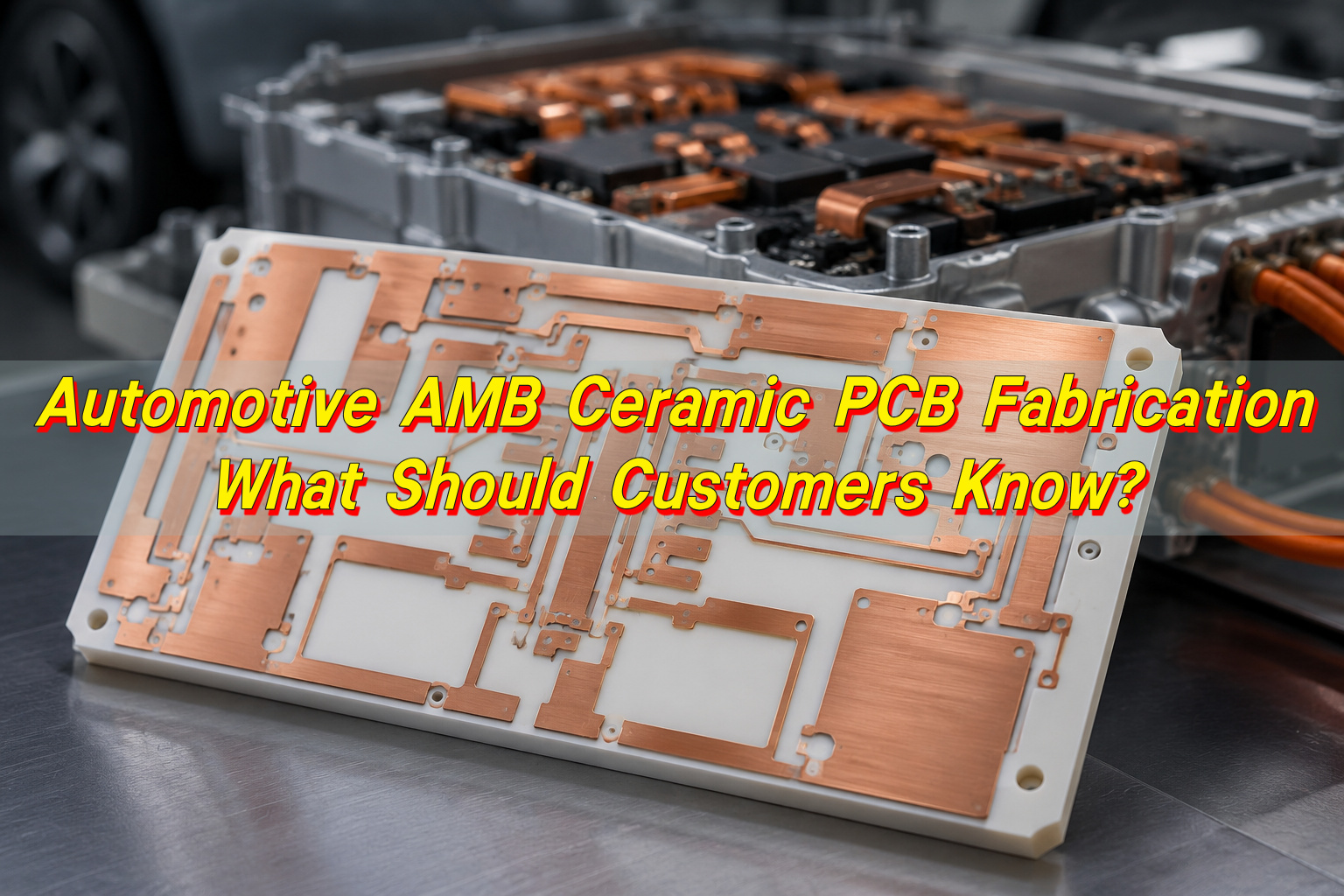
Automotive AMB ceramic PCB fabrication is the production of copper-bonded ceramic substrates for vehicle power electronics, especially where high current, insulation, heat spreading, and thermal cycling resistance must be reviewed together. The process creates a metalized ceramic circuit carrier rather than a conventional organic laminate PCB.
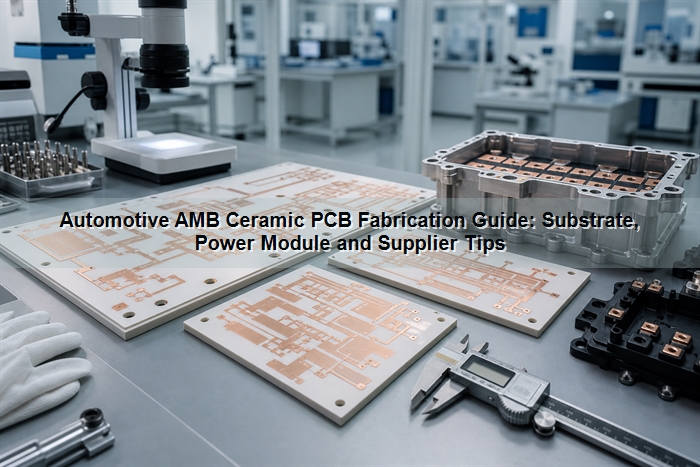
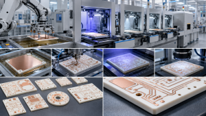
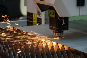
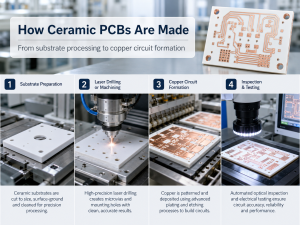
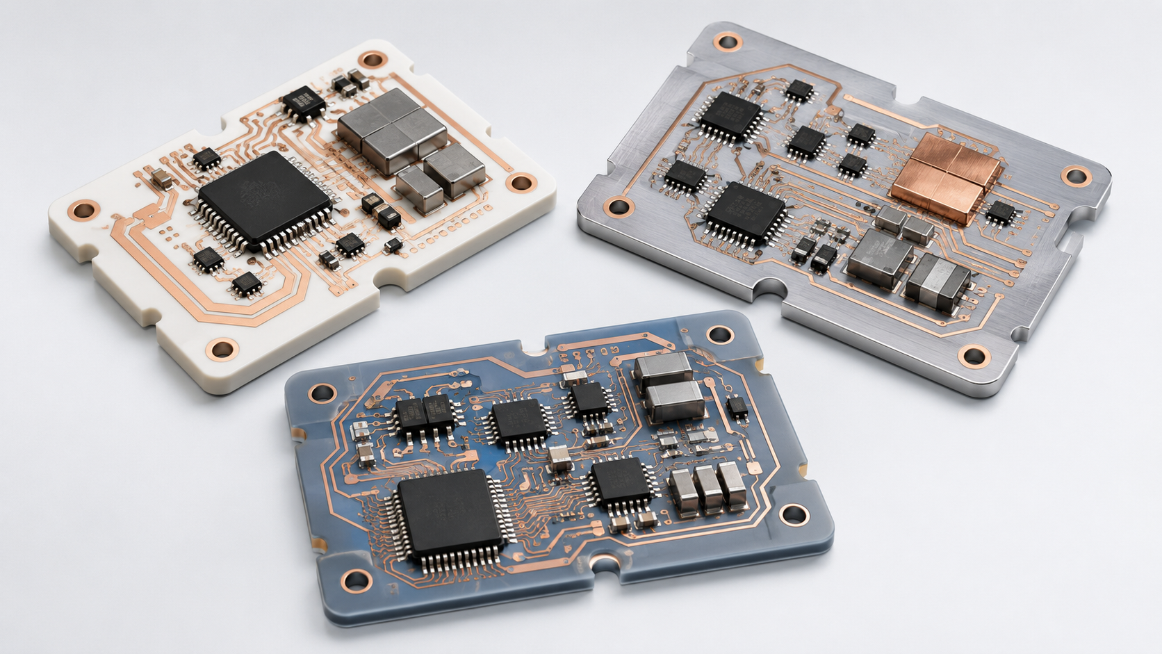
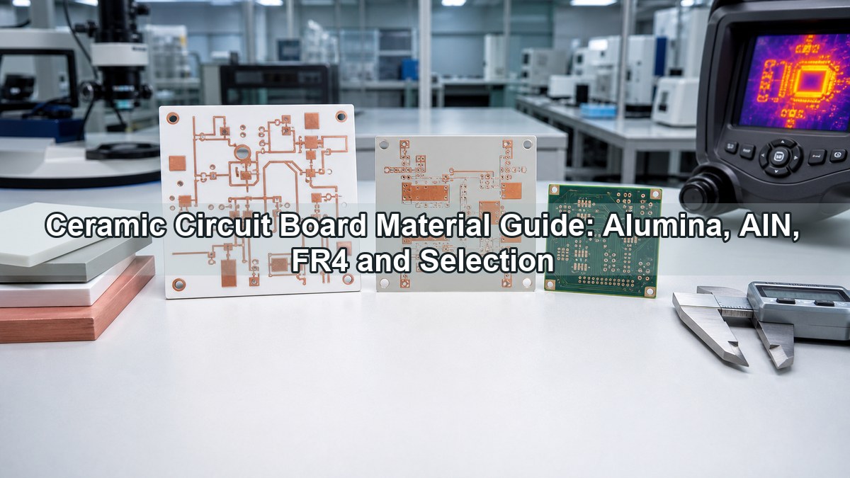
Automotive AMB ceramic PCB fabrication scene with ceramic substrates and power module inspection

In the fabrication flow, the supplier reviews the drawing, ceramic type, copper thickness, conductor pattern, isolation distance, surface finish, edge tolerance, and sample quantity before confirming the route. For automotive projects, the review should also include thermal cycling expectations, partial discharge or dielectric requirements when applicable, and whether the prototype must represent the future production process.

Compared with standard FR4 PCB or metal-core PCB, AMB is usually considered for higher-power sections of the system, not low-power control electronics. It belongs in the same decision space as ceramic PCB, DBC ceramic substrates, and other power electronic substrate technologies.

Why Are AMB Ceramic Substrates Used in Automotive Power Modules?

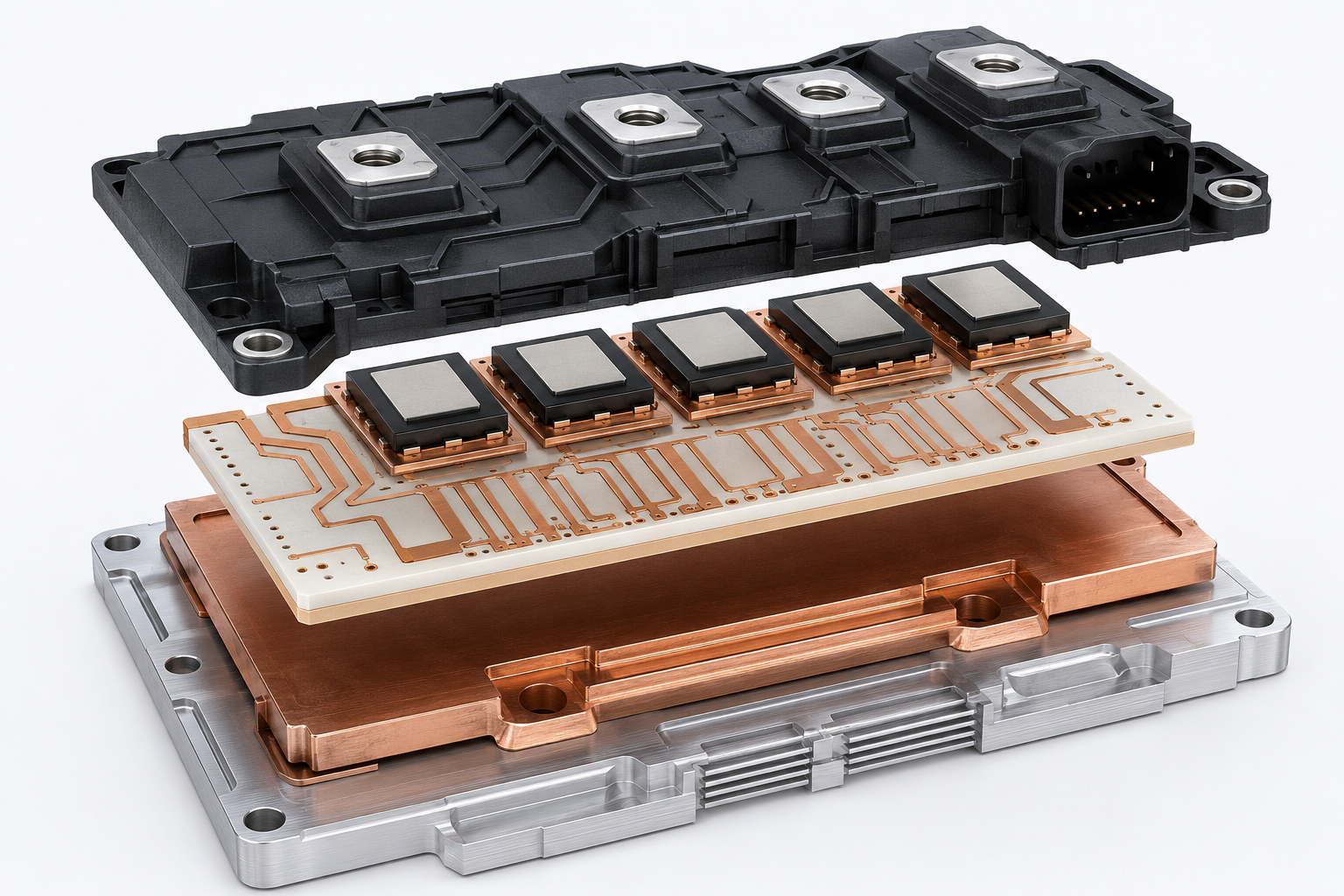
AMB ceramic substrates are used in automotive power modules because they combine electrical insulation, heat transfer, copper current paths, and stronger copper-to-ceramic bonding for harsh power cycling conditions. This matters most when the module carries IGBT, SiC MOSFET, diode, or power-dense switching components in an EV inverter, DC-DC converter, onboard charger, or motor control unit.
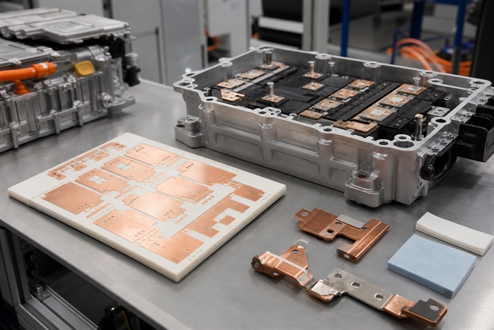
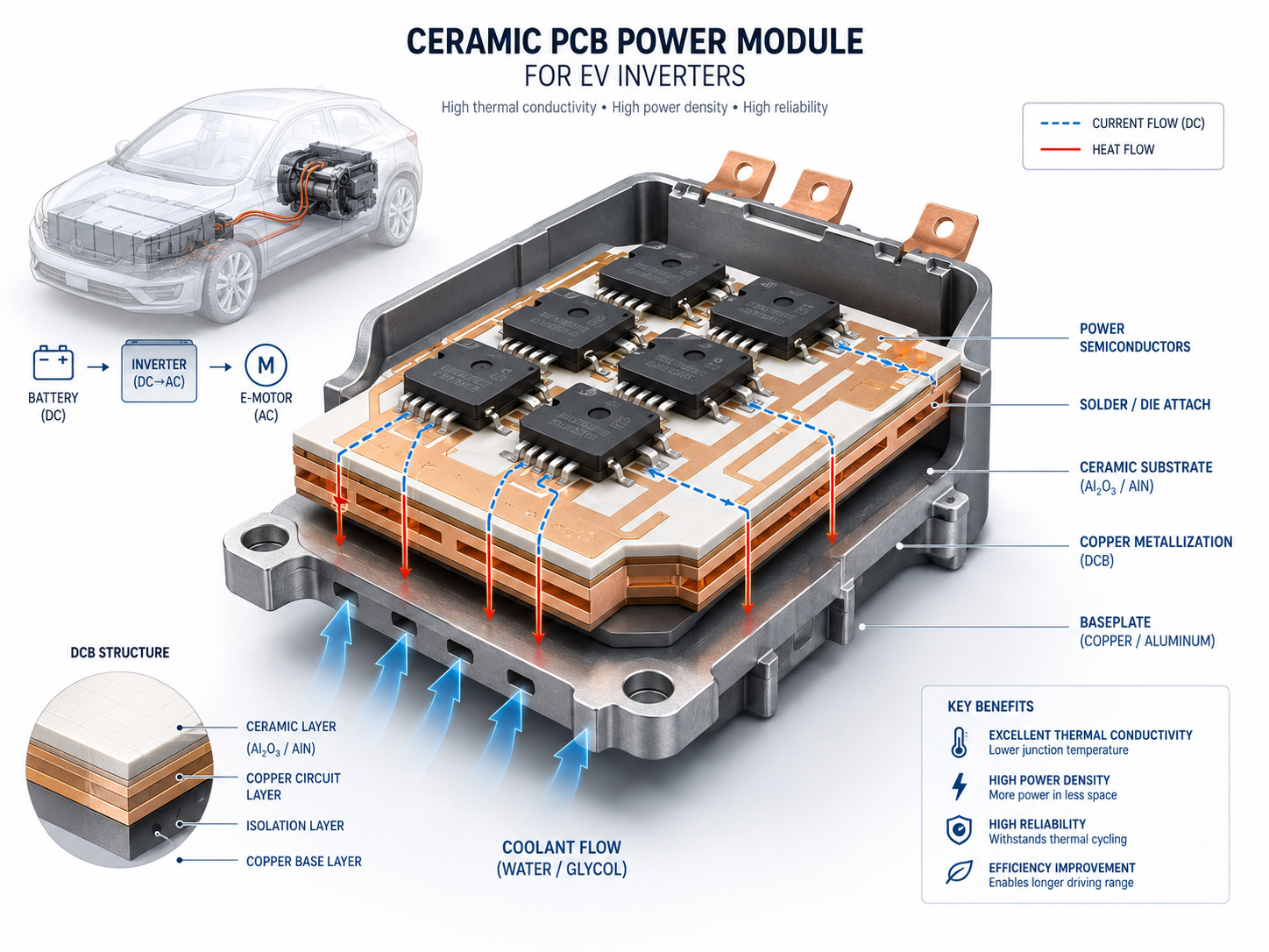
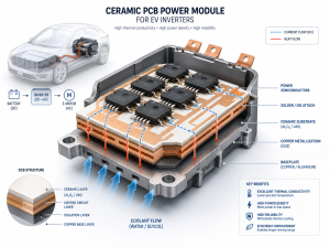
AMB ceramic substrate used inside an automotive power module assembly

The core design logic is stress management. Power devices heat and cool quickly, while copper, ceramic, solder, die attach, and baseplate materials expand differently. If the substrate cannot manage this mismatch, the module may suffer copper delamination, ceramic cracking, solder fatigue, increased thermal resistance, or early electrical failure.

AMB is not necessary for every automotive PCB component. Low-current sensor boards, control boards, lighting controllers, and communication boards may use FR4, high-Tg FR4, rigid-flex, or MCPCB depending on temperature and mechanical requirements. AMB becomes relevant when the circuit carrier is part of the thermal and mechanical reliability path of the power module.

How Does AMB Ceramic Compare with DBC and DPC?

The choice between AMB, DBC, and DPC should start with power density, copper thickness, line resolution, material, and thermal cycling risk. AMB is often considered when mechanical reliability and copper bonding strength matter more than very fine conductor geometry.
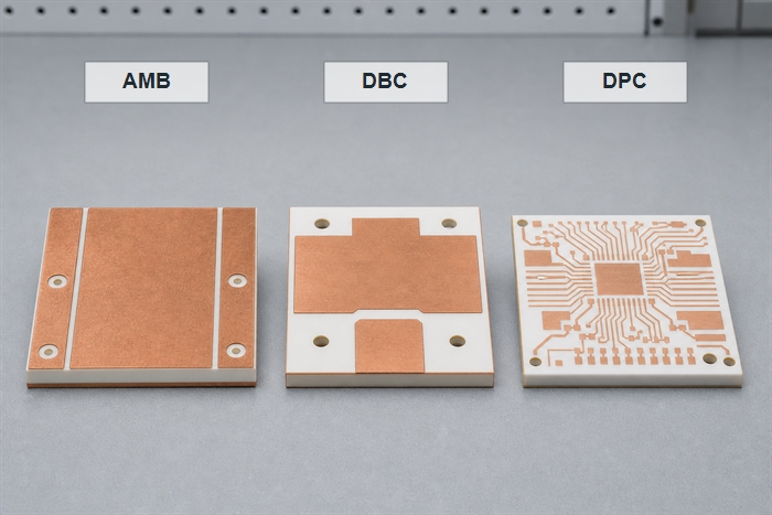
Comparison image showing AMB DBC and DPC ceramic substrate options for power modules
Technology Best fit Buyer should check
AMB ceramic substrate High-reliability power modules, especially with Si3N4 or demanding thermal cycling Brazing quality, copper adhesion, ceramic toughness, voids, and thermal cycling data
DBC / DCB ceramic substrate Mature power module designs that need thick copper and strong heat spreading Ceramic type, copper thickness, etching limits, dielectric strength, and solderability
DPC ceramic PCB Finer conductor patterns, smaller features, or designs needing plated structures Line width, via structure, plating thickness, and whether current capacity is sufficient

If the design combines high current, thick copper, and severe thermal cycling, AMB or DBC should usually be evaluated before DPC. If the design needs finer routing and lower current, DPC may be more practical. For an RFQ, ask the supplier to explain the process recommendation instead of quoting only the requested keyword.

Which Materials Matter in AMB Ceramic PCB Fabrication?

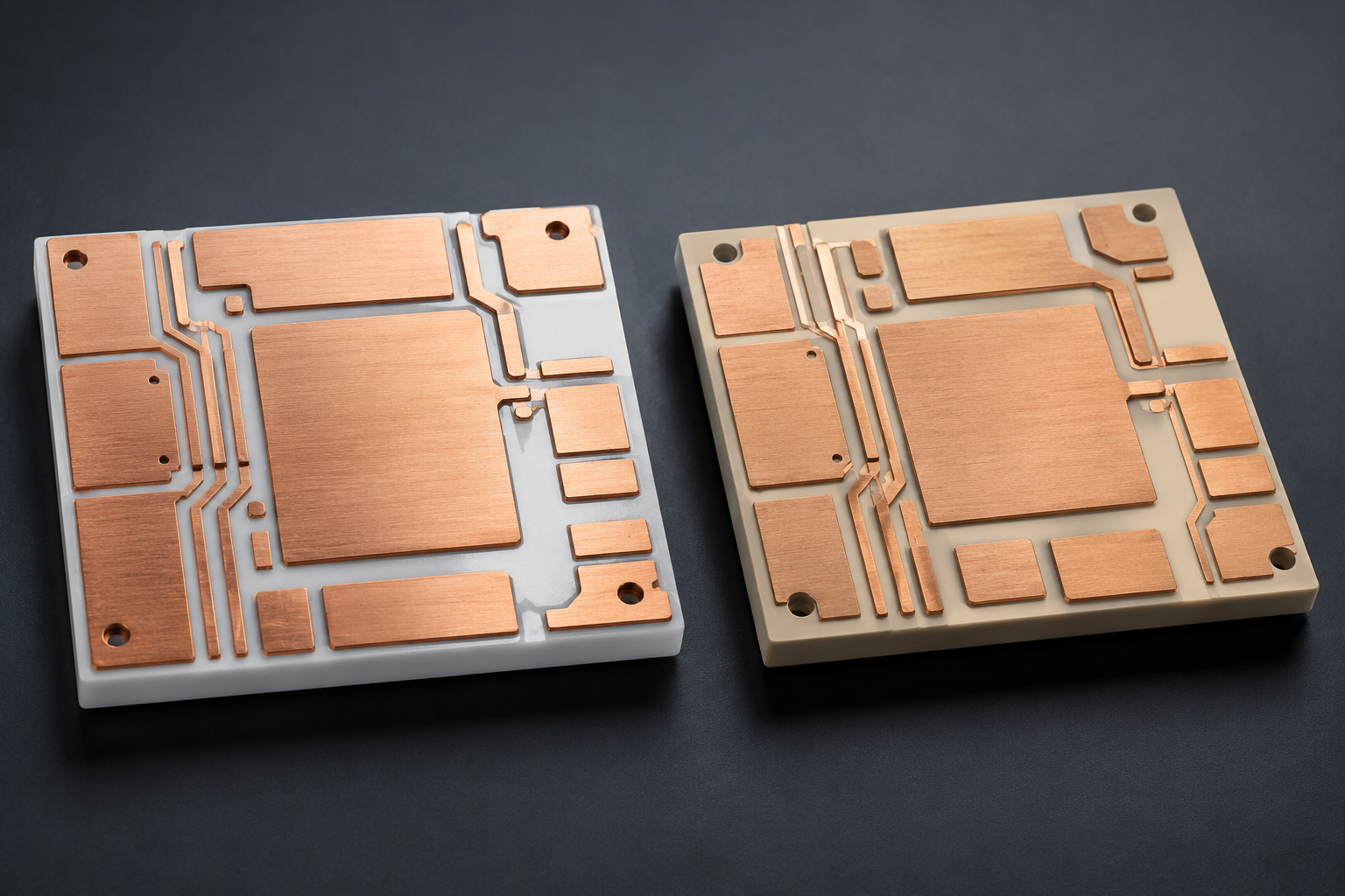
The main materials in AMB ceramic PCB fabrication are the ceramic substrate, copper layer, active brazing material, and final surface finish. For automotive power modules, the ceramic choice can affect thermal conductivity, bending strength, fracture toughness, dielectric behavior, and long-term cycling performance.
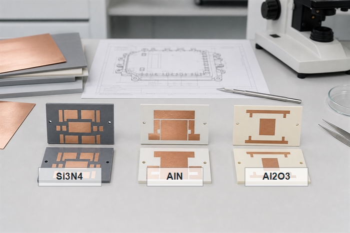
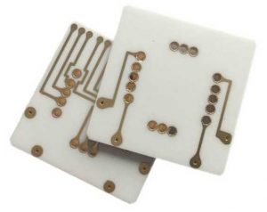
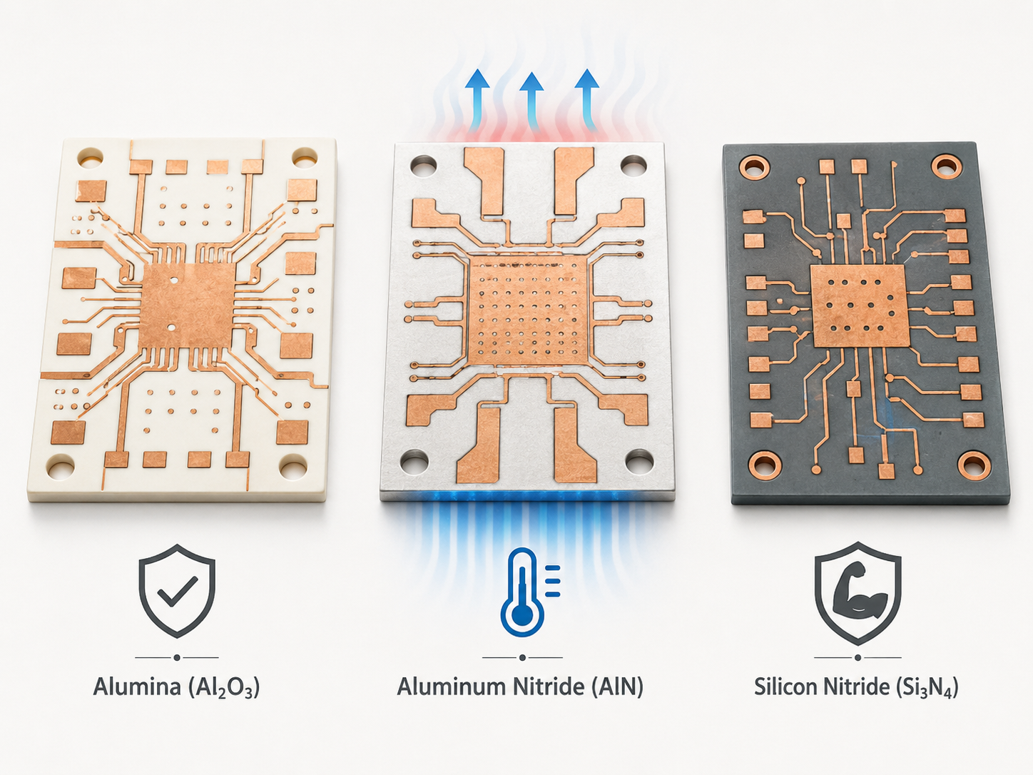
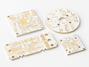
AMB ceramic substrate material selection showing Si3N4 AlN and Al2O3 ceramic samples with copper patterns
Material Why buyers consider it Practical caution
Si3N4 Often selected for higher mechanical toughness and thermal cycling resistance in demanding power modules Cost, availability, thickness, and supplier process maturity should be confirmed early
AlN Selected when high thermal conductivity is a primary driver Mechanical robustness and cycling performance must be reviewed with the exact module design
Al2O3 Useful when cost and insulation matter more than maximum thermal performance May not be enough for high-power automotive modules with aggressive heat density

For high-risk automotive applications, do not choose only by thermal conductivity. A substrate with higher thermal conductivity but lower mechanical margin may still create reliability risk if the copper thickness, die attach, baseplate, and thermal cycling profile are not matched.

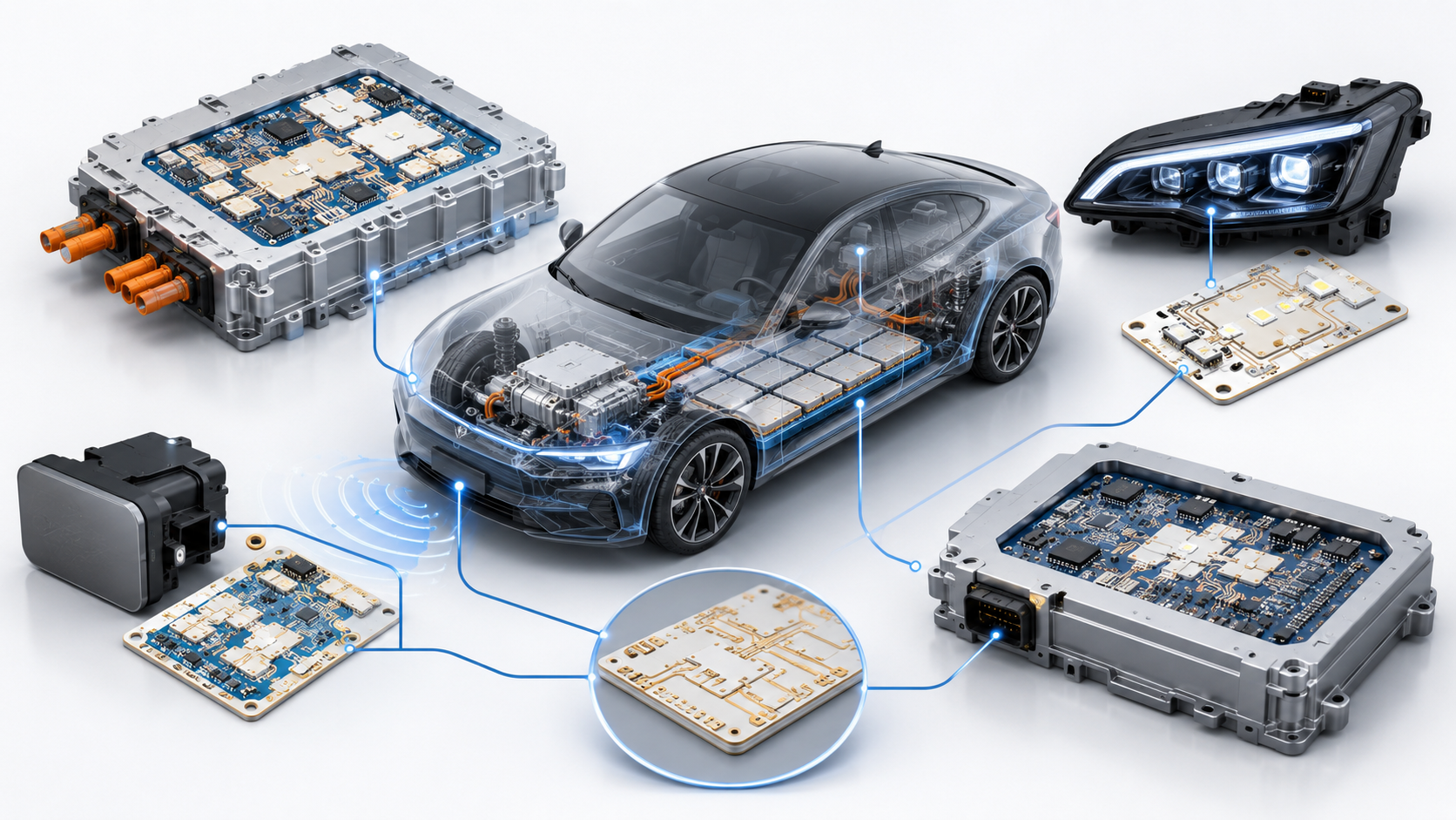
What Automotive PCB Components Use AMB Ceramic Substrates?

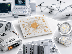
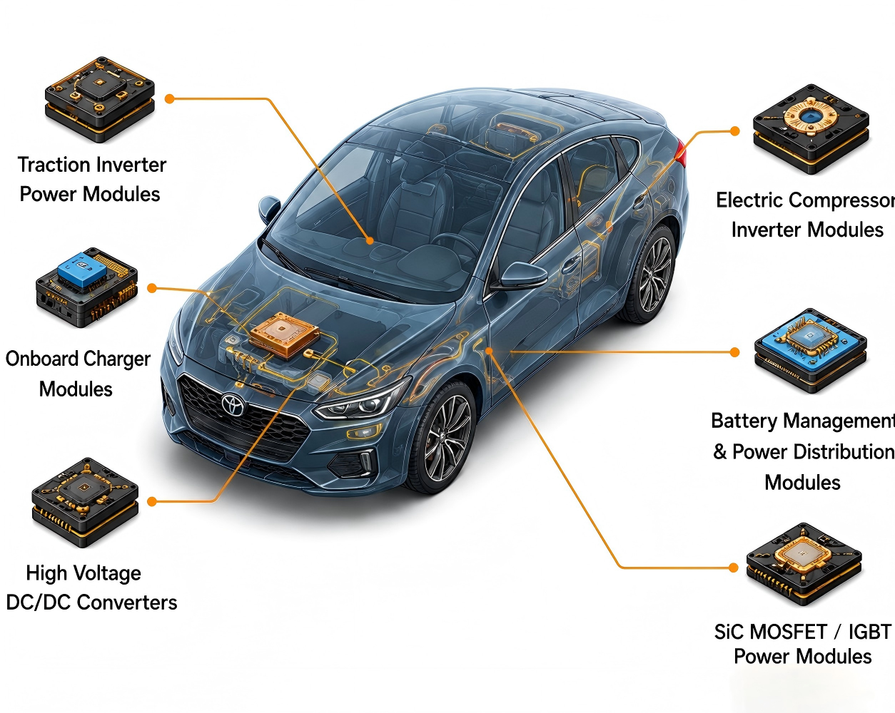
AMB ceramic substrates are mainly used in automotive power electronics components where the circuit carrier is exposed to high heat flux, high current, and repeated load changes. They are less relevant for ordinary logic boards and more relevant for modules that sit close to power semiconductor devices.

  • EV traction inverter power modules using SiC MOSFETs, IGBTs, or diodes.
  • Onboard charger power conversion modules.
  • DC-DC converter modules for high-voltage to low-voltage conversion.
  • Motor control modules and high-load switching units.
  • Battery thermal management or high-current protection circuits when ceramic isolation and heat spreading are needed.

For mixed automotive PCB assemblies, the AMB substrate is often only one part of the full electronic system. The surrounding gate driver, sensing, communication, and control circuits may still use conventional PCB or PCBA processes, so the supplier handoff between ceramic substrate fabrication and assembly review should be planned early.

What Manufacturing Factors Affect AMB Ceramic PCB Quality?

AMB ceramic PCB quality is strongly affected by ceramic preparation, copper thickness, brazing interface quality, pattern etching, surface finish, edge processing, and inspection. A buyer should review these factors before approving a prototype because they influence both electrical performance and long-term mechanical reliability.

  • Copper thickness: affects current carrying capacity, heat spreading, etching geometry, and stress at the copper-to-ceramic interface.
  • Pattern geometry: sharp corners, narrow gaps, large copper islands, and asymmetric copper balance can change stress concentration.
  • Brazing interface: voids, poor wetting, or inconsistent bonding can increase thermal resistance and reduce cycling life.
  • Ceramic edge quality: chips, microcracks, and rough edges can create handling and reliability risk.
  • Surface finish: should match die attach, soldering, wire bonding, or module assembly requirements.

EBest Circuit (Best Technology) lists AMB ceramic PCB among its ceramic PCB technology scope, together with DPC, DBC/DCB, LTCC, HTCC, thick-film, and thin-film ceramic PCB. For automotive use, any maximum capability or fast-turn request should still be checked against material, dimensions, copper thickness, testing scope, and engineering review.

What Reliability Tests Matter for Automotive AMB Ceramic PCB?

Reliability testing for automotive AMB ceramic PCB should focus on thermal cycling, power cycling relevance, insulation, copper adhesion, dimensional stability, solderability, and visual or microstructural inspection. The exact test plan should match the module’s voltage class, mission profile, assembly method, and customer qualification standard.
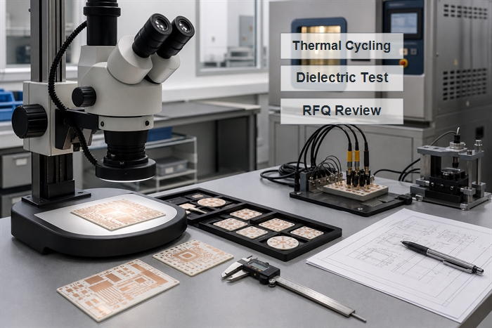
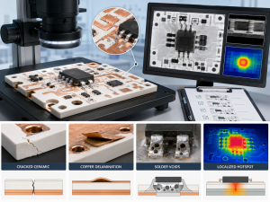
Automotive AMB ceramic PCB reliability testing with thermal cycling inspection and electrical test equipment
Check Why it matters Buyer action
Thermal cycling Finds stress-related issues at the copper, braze, ceramic, and solder interfaces Share the expected temperature range and cycle target before quoting
Dielectric / insulation testing Confirms isolation margin for high-voltage automotive modules Specify voltage, spacing, and acceptance criteria
Microsection or interface review Helps evaluate voids, bonding quality, copper thickness, and process consistency Request sample inspection data for critical prototype builds
Dimensional inspection Protects module fit, die placement, and baseplate alignment Mark critical dimensions separately from non-critical dimensions

For SiC traction inverter modules, power cycling is especially relevant because it stresses the package under realistic electrical and thermal load changes. Even when the AMB supplier does not run full module-level power cycling, the substrate design should be reviewed with that stress path in mind.

What Should Buyers Provide for an AMB Ceramic PCB Quote?

A useful AMB ceramic PCB quote requires more than Gerber files. The supplier needs enough design and application context to judge material fit, copper thickness, brazing route, test requirements, and whether the prototype can scale to automotive production.

  • Gerber, drill, drawing, and copper layer data.
  • Ceramic material preference, such as Si3N4, AlN, or Al2O3.
  • Copper thickness, substrate thickness, and finished board thickness.
  • Surface finish and assembly method, including soldering, die attach, or wire bonding needs.
  • Voltage, current, insulation distance, and thermal load targets.
  • Critical dimensions, tolerance class, and edge quality requirements.
  • Prototype quantity, expected production volume, and PPAP or automotive documentation expectations.
  • Required inspection reports, thermal cycling requirements, and packaging instructions.

If the project includes assembled automotive PCB components, send BOM, placement data, thermal interface notes, and test requirements at the same time. This lets the supplier check substrate fabrication and downstream assembly risks together instead of discovering mismatches after samples are made.

How to Choose Automotive PCB Suppliers for AMB Ceramic Projects?

Automotive PCB suppliers for AMB ceramic projects should be evaluated by engineering review quality, ceramic substrate experience, inspection capability, documentation discipline, and ability to support prototype-to-production transfer. A supplier that can quote quickly but cannot explain material trade-offs may create risk during qualification.

Ask each supplier how they review Si3N4 versus AlN, which copper thicknesses fit the selected process, what inspection data can be provided for prototypes, how they control edge damage, and what information is needed before mass production. If automotive documentation is required, confirm expectations before the prototype order, not after the design is frozen.

EBest Circuit (Best Technology) can be positioned as a ceramic PCB and PCBA manufacturing partner for buyers who need engineering communication across prototype review, ceramic substrate fabrication, assembly discussion, and quotation preparation. For AMB projects, the useful conversation is not a generic price request; it is a file-and-requirement review that connects material choice, reliability target, and production feasibility.

FAQ

What is AMB ceramic PCB fabrication used for in automotive electronics?

AMB ceramic PCB fabrication is used for high-power automotive electronics where the substrate must provide insulation, heat spreading, copper current paths, and thermal cycling resistance. Typical uses include EV inverter power modules, onboard chargers, DC-DC converters, motor control modules, and other circuits that place SiC MOSFETs, IGBTs, or diodes close to the heat path.

Is AMB ceramic better than DBC for automotive power modules?

AMB is not automatically better than DBC; it is better suited when the design needs stronger copper-to-ceramic bonding and improved mechanical reliability under severe thermal cycling. DBC remains a mature option for many power modules. The correct choice depends on ceramic material, copper thickness, module stress profile, cost target, and qualification requirements.

Which ceramic material is best for AMB power modules?

Si3N4 is often considered for demanding AMB power modules because it offers strong mechanical toughness and thermal cycling resistance. AlN is attractive when thermal conductivity is the main driver, while Al2O3 is more cost-oriented but usually less suitable for high-power automotive modules. Buyers should review material choice with copper thickness, module layout, and test requirements together.

What files are needed for an automotive AMB ceramic PCB quote?

A useful quote should include Gerber data, mechanical drawings, ceramic material preference, copper thickness, substrate thickness, surface finish, voltage and current targets, thermal load, critical tolerances, sample quantity, production estimate, and reliability test expectations. If assembly is involved, include BOM, placement data, die attach or soldering notes, and packaging requirements.

Can AMB ceramic substrates be assembled into automotive power modules?

Yes, AMB ceramic substrates can be used in automotive power module assembly, but the assembly method must be reviewed early. Die attach, solderability, wire bonding, surface finish, baseplate attachment, insulation spacing, and thermal interface materials can all affect reliability. The substrate supplier and assembly team should align before prototype approval.

How should buyers evaluate automotive PCB suppliers for AMB ceramic projects?

Buyers should evaluate whether the supplier can review ceramic material, copper thickness, AMB process route, edge quality, inspection data, thermal cycling expectations, and prototype-to-production transfer. For automotive projects, also check documentation discipline, traceability expectations, quality system fit, and whether the supplier can explain trade-offs instead of only quoting a price.

Conclusion

Automotive AMB ceramic PCB fabrication is most useful when the design needs a ceramic power substrate for high current, heat spreading, insulation, and thermal cycling reliability. It is not the default choice for every automotive PCB; it should be selected when the power module’s stress profile, device type, copper requirement, and qualification plan justify the process.

Before requesting a quote, prepare the material target, copper thickness, drawings, electrical and thermal requirements, prototype quantity, expected production volume, and reliability test expectations. If you are evaluating AMB ceramic substrates for automotive power modules, contact EBest Circuit (Best Technology) at sales@bestpcbs.com for engineering review and quotation support.

You may also like

Ceramic PCB for Automotive Electronics: What Should Customers Know?
Thursday, July 2nd, 2026

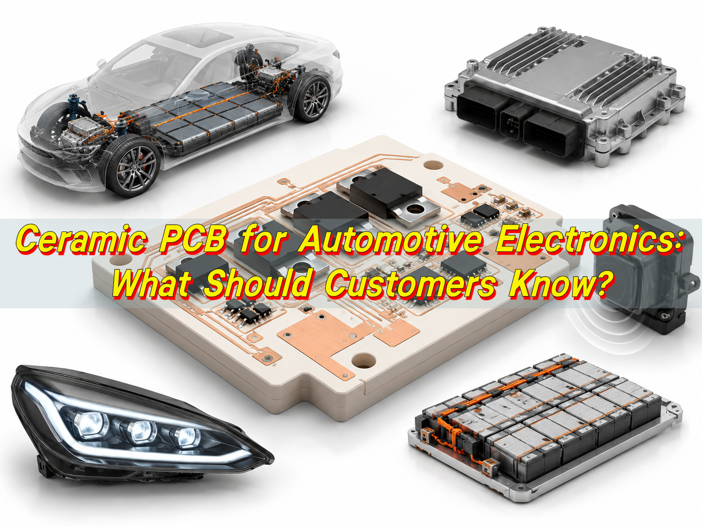
Ceramic PCB for automotive electronics is becoming an important choice in EV inverters, LED headlights, onboard chargers, DC-DC converters, sensors, and battery systems. In these applications, the circuit board often does more than connect components. It also helps transfer heat, provide insulation, and support long-term reliability in compact automotive modules.

Ceramic PCB for Automotive Electronics: What Should Customers Know?

A ceramic PCB for automotive electronics is used when FR4 cannot provide enough thermal performance, voltage insulation, or stability in a compact structure. It is not the right choice for every automotive board. For many control circuits, FR4 remains practical and cost-effective. Ceramic PCB becomes valuable when the board is close to heat sources, power devices, high-current paths, or high-voltage sections.

EBest Circuit supports ceramic PCB manufacturing, ceramic PCB prototypes, and PCB assembly for automotive and EV applications. For customers, the best starting point is simple: define the heat, voltage, current, space, and reliability requirements before choosing the substrate.

What Is a Ceramic PCB for Automotive Electronics?

A ceramic PCB for automotive electronics is a circuit board or substrate that uses ceramic material as the base instead of FR4 laminate. Common ceramic materials include alumina, aluminum nitride, and silicon nitride. Copper circuits are formed on the ceramic surface through DPC, DBC, AMB, thick film, thin film, or other metallization processes.

The main purpose of using ceramic is to combine electrical insulation with heat transfer. This is useful in automotive systems where heat must move from power devices to a heat sink, metal housing, or cooling plate while the circuit remains electrically isolated.

Ceramic PCB boards are commonly used in EV power modules, automotive LED lighting, onboard chargers, DC-DC converters, high-temperature sensors, heater circuits, and powertrain modules. A small alumina sensor substrate and a thick copper AMB substrate for an EV drive system are both ceramic-based products, but their structures and costs are very different.

For customers requesting a ceramic PCB prototype, the process type matters. DPC is often used for fine circuit patterns. DBC and AMB are better suited for thick copper, high current, and power module applications. Thick film ceramic circuits are used when printed resistors, heater traces, or functional paste layers are required.

Why Are Ceramic PCBs Used in Automotive Electronics?

Ceramic PCBs are used when the board must handle heat, voltage, or harsh working conditions better than standard FR4. In automotive electronics, this usually happens near power semiconductors, LEDs, balancing resistors, current sensors, heating elements, and high-voltage power sections.

The biggest advantage is thermal performance. FR4 is a poor heat conductor. Ceramic materials can transfer heat more efficiently while still providing insulation. This makes them useful in modules where the substrate sits between a hot component and a cooling structure.

Ceramic PCBs are also stable under temperature changes. Vehicle electronics go through repeated heating and cooling during driving, charging, parking, and load changes. A stable ceramic substrate helps reduce stress on solder joints, copper layers, chips, and bonded interfaces.

Ceramic PCB is usually worth considering when the design has:

  • High heat in a small area
  • High-voltage insulation requirements
  • Power devices mounted close to the substrate
  • Limited space for heat sinks or airflow
  • Repeated thermal cycling
  • Thick copper or high-current paths
  • A need for long-term stability in a harsh environment

If the board mainly carries signals or low-power control circuits, FR4 is usually enough. Ceramic should be used where it solves a clear engineering problem.

How Is a Ceramic PCB Board Different from an FR4 PCB?

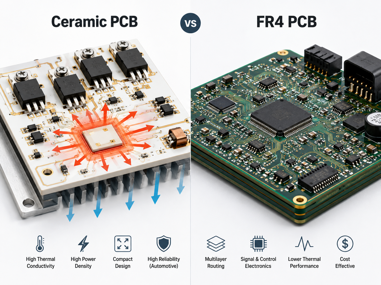
Ceramic PCB and FR4 PCB are used for different design priorities. FR4 is strong in routing flexibility, multilayer design, cost control, and general electronics. Ceramic PCB is stronger in heat transfer, insulation, dimensional stability, and power-density applications.

Ceramic PCB for Automotive Electronics: What Should Customers Know?
ItemCeramic PCB BoardFR4 PCB
Base materialAlumina, AlN, Si3N4, or other ceramicGlass fiber and epoxy resin
Main valueThermal transfer and insulationRouting flexibility and cost control
Thermal conductivityMuch higher, depending on ceramic typeLow, commonly around 0.25–0.35 W/m·K
Heat resistanceStrong in high-temperature areasLimited by resin system and Tg grade
Electrical insulationExcellent for power and high-voltage useGood for standard circuits
Copper structureCan support thick copper in DBC or AMBBetter for standard multilayer PCB routing
Typical useEV power modules, LEDs, sensors, power convertersECU, BMS control board, infotainment, body electronics
CostHigherLower

FR4 is the better first choice for control boards, communication boards, and cost-sensitive electronics. Ceramic PCB is the better option when the board must act as a thermal path or an insulating power substrate.

When Should You Choose Ceramic Substrate vs FR4 in Automotive Electronics?

Choose ceramic substrate when heat, voltage, or current density is the design limit. Choose FR4 when the board mainly needs signal routing, control, and standard assembly.

In many automotive products, both materials can be used in the same system. For example, an EV charger may use FR4 for the control board and ceramic substrate for the power section. A BMS may use FR4 for monitoring and communication, while using ceramic near balancing resistors or heat-generating parts.

Design ConditionBetter ChoiceReason
Low-power control circuitFR4 PCBLower cost and easier multilayer routing
Infotainment or communication boardFR4 PCBBetter for dense signal routing
High-power LED moduleAlN ceramic PCB or metal core PCBBetter heat transfer
EV inverter power stageDBC or AMB ceramic substrateHandles heat, current, and insulation
BMS main control boardFR4 PCBMostly signal and monitoring circuits
BMS resistor hot zoneCeramic PCB or metal core PCBHelps spread local heat
High-temperature sensorAlumina or AlN ceramic PCBStable near heat sources
Compact DC-DC converterCeramic PCBReduces thermal resistance

Before choosing ceramic, customers should provide power loss, current load, operating voltage, target temperature, board size, copper thickness, cooling method, and assembly requirements. Without these details, material selection is incomplete.

What Ceramic PCB Materials Are Used in Automotive Applications?

The main ceramic PCB materials for automotive applications are alumina, aluminum nitride, and silicon nitride. Each material fits a different use case.

Alumina is the most common option. It is stable, insulating, mature in production, and more economical than AlN or Si3N4. It is often used for sensors, thick film circuits, heater circuits, and moderate-power modules.

Ceramic PCB for Automotive Electronics: What Should Customers Know?

Aluminum nitride is selected when heat transfer is the main requirement. It has much higher thermal conductivity than alumina and is widely used in automotive LED lighting, compact power modules, and high-heat areas.

Silicon nitride is selected for mechanical reliability and thermal cycling performance. It is often used in AMB substrates for EV inverter and drive system modules.

Material or StructureMain FeatureAutomotive Use
Alumina ceramicStable, insulating, cost-effectiveSensors, heater circuits, thick film modules
AlN ceramicHigh thermal conductivityLED lighting, power modules, compact thermal designs
Si3N4 ceramicStrong thermal cycling reliabilityEV inverter and drive systems
DPC ceramic PCBFine circuits and plated copperLEDs, sensors, precision circuits
DBC ceramic substrateThick copper bonded to ceramicPower modules and high-current circuits
AMB ceramic substrateStrong copper-to-ceramic bondingEV drive systems and SiC power modules
Thick film ceramicPrinted conductor or resistor layersSensors and heater modules

Material selection should not rely only on thermal conductivity. Copper thickness, ceramic thickness, bonding strength, insulation distance, surface finish, assembly process, and cost target should also be reviewed.

Why Is AlN Ceramic PCB Used for Automotive LED Lighting?

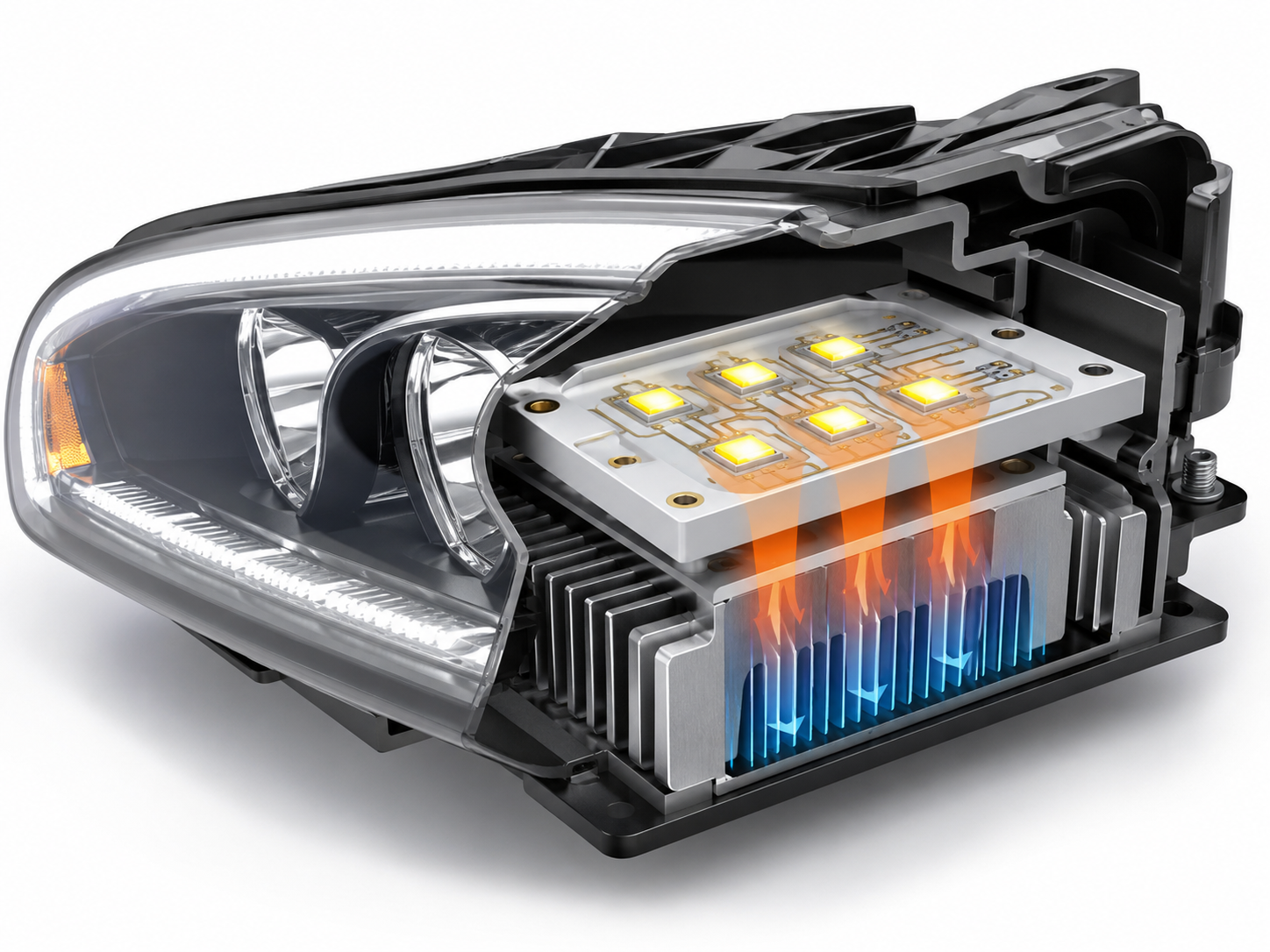
AlN ceramic PCB is used in automotive LED lighting because high-power LEDs generate concentrated heat. In headlights, daytime running lights, matrix LED systems, and EV lighting modules, the board must move heat away from the LED package quickly.

AlN provides a strong thermal path while keeping electrical insulation. This helps the lighting module maintain stable brightness, color consistency, and service life. It is especially useful in compact lamp designs where airflow is limited and the heat sink area is small.

Ceramic PCB for Automotive Electronics: What Should Customers Know?

The thermal path usually follows this route: LED package, solder joint, copper layer, AlN ceramic substrate, thermal interface material, heat sink, and lamp housing. The ceramic board improves the substrate part of this path, but the full structure must also be well designed.

Lighting RequirementWhy AlN Helps
High LED power densityTransfers heat away from small LED areas
Slim lamp structureSupports compact thermal design
Matrix LED layoutHelps manage multiple heat sources
Stable brightnessReduces excessive temperature rise
Color consistencyKeeps LED operation more stable
Electrical insulationIsolates copper circuits from the housing

For customers, LED power, copper thickness, soldering method, housing design, thermal interface material, and surface finish should be confirmed before making an AlN ceramic PCB prototype.

How Does Ceramic PCB Thermal Conductivity Help EV Systems?

Ceramic PCB thermal conductivity helps EV systems by reducing the thermal bottleneck between power components and the cooling structure. This is important in inverters, onboard chargers, DC-DC converters, power distribution units, LED drivers, and battery-related circuits.

MaterialTypical Thermal Conductivity RangeMeaning in EV Systems
FR4About 0.25–0.35 W/m·KSuitable for control and signal boards
Alumina ceramicAbout 20–30 W/m·KGood for cost-balanced ceramic designs
AlN ceramicAbout 140–180 W/m·KStrong for compact high-power modules
Si3N4 ceramicAbout 70–90 W/m·KGood for thermal cycling reliability
CopperAbout 400 W/m·KUsed for current and heat spreading

Higher thermal conductivity helps move heat away from IGBTs, SiC MOSFETs, LEDs, power resistors, and other hot components. However, customers should not look at substrate thermal conductivity alone. Total thermal resistance is more important.

Ceramic thickness, copper thickness, solder layer, thermal interface material, heat sink contact, mounting pressure, and cooling method all affect final temperature. A high-performance ceramic substrate still needs a good mechanical and thermal design around it.

How Are Ceramic PCBs Used in EV Power Electronics?

Ceramic PCBs are used in EV power electronics as insulating thermal substrates. They support power devices, carry current through copper, transfer heat to the cooler, and maintain electrical isolation.

In traction inverters, ceramic substrates are often used under IGBTs or SiC MOSFETs. Heat moves from the semiconductor into copper, through the ceramic, and toward the cooling plate. The ceramic layer keeps the high-voltage circuit isolated from the cooler.

Ceramic PCB for Automotive Electronics: What Should Customers Know?

In onboard chargers, ceramic boards can be used near switching devices, rectifiers, and other heat-generating power components. In DC-DC converters, ceramic substrates may be used in the power section, while FR4 remains suitable for the control section.

Typical applications include:

  • Traction inverter power modules
  • SiC MOSFET and IGBT substrates
  • Onboard charger power sections
  • DC-DC converter thermal modules
  • Power distribution circuits
  • Electric compressor drive electronics
  • High-power LED driver modules
  • Ceramic PCB assembly for powertrain modules

For EV power electronics, copper design is critical. Copper thickness affects current capacity and heat spreading. Copper shape affects stress. Isolation gaps affect voltage safety. Ceramic thickness affects thermal resistance and mechanical strength. These details should be checked before prototype production.

How Is AMB Ceramic PCB Used in Electric Vehicle Drive Systems?

AMB ceramic PCB is used in electric vehicle drive systems as a high-reliability power substrate. AMB means Active Metal Brazing. Copper is bonded to ceramic through an active brazing alloy, creating a strong copper-to-ceramic connection.

EV drive systems create repeated heating and cooling during acceleration, regenerative braking, and load changes. The substrate must handle current, heat, insulation, vibration, and thermal cycling. AMB is selected when bonding strength and long-term reliability are more important than lowest cost.

AMB substrates are commonly made with AlN or Si3N4. AlN AMB is used when high thermal conductivity is the priority. Si3N4 AMB is used when thermal cycling and mechanical reliability are more important.

Substrate TypeMain FeatureAutomotive Use
Alumina DBCMature and cost-effectiveStandard power modules
AlN DBCBetter heat transferHigher power-density modules
AlN AMBHigh thermal transfer and strong bondingCompact power modules
Si3N4 AMBStrong thermal cycling reliabilityEV traction inverter modules

AMB ceramic PCB is especially useful for SiC power modules. SiC devices can operate at high power density, so the substrate must support concentrated heat and strong copper adhesion. AMB gives the module a more robust base for demanding drive system conditions.

Can Ceramic PCBs Be Used for BMS in Electric Vehicles?

Ceramic PCBs can be used for BMS in electric vehicles, but usually only in selected areas. Most BMS main boards use FR4 because they handle voltage monitoring, communication, control, and low-power signal processing.

Ceramic becomes useful where heat or insulation stress is higher. The most common example is the balancing resistor area. During cell balancing, resistors can generate local heat. A ceramic substrate can help spread that heat and protect nearby components.

Ceramic PCB may also be considered for current sensing areas, temperature sensing modules, compact protection circuits, or battery modules exposed to elevated temperature.

BMS AreaSuitable PCB ChoiceReason
Main control boardFR4 PCBGood for signal routing and cost control
Communication circuitFR4 PCBLow power and standard assembly
Voltage monitoring boardFR4 or ceramic PCBDepends on location and insulation need
Balancing resistor areaCeramic PCB or metal core PCBBetter local heat spreading
Temperature sensing moduleAlumina ceramic PCB or FR4 PCBDepends on operating temperature
Current sensing areaCeramic PCB may be usefulHelps thermal stability
High-temperature battery areaCeramic PCBBetter stability near heat sources

For BMS projects, the best choice is often mixed-material design. Use FR4 for control and communication. Use ceramic only where heat, insulation, or reliability requires it. This keeps the design practical and avoids unnecessary cost.

In short, ceramic PCB for automotive electronics is suitable for high-heat, high-voltage, high-current, and compact power applications. FR4 remains suitable for many automotive control and signal boards. Ceramic substrates are stronger choices for EV power electronics, automotive LED lighting, sensors, BMS hot zones, and electric vehicle drive systems.

EBest Circuit provides ceramic PCB manufacturing, ceramic PCB prototype service, and PCB assembly support for automotive and EV-related projects. If you need ceramic PCB for automotive electronics, EV power modules, automotive LED lighting, BMS thermal circuits, or ceramic PCB assembly for powertrain modules, contact sales@bestpcbs.com for project review and quotation.

You may also like

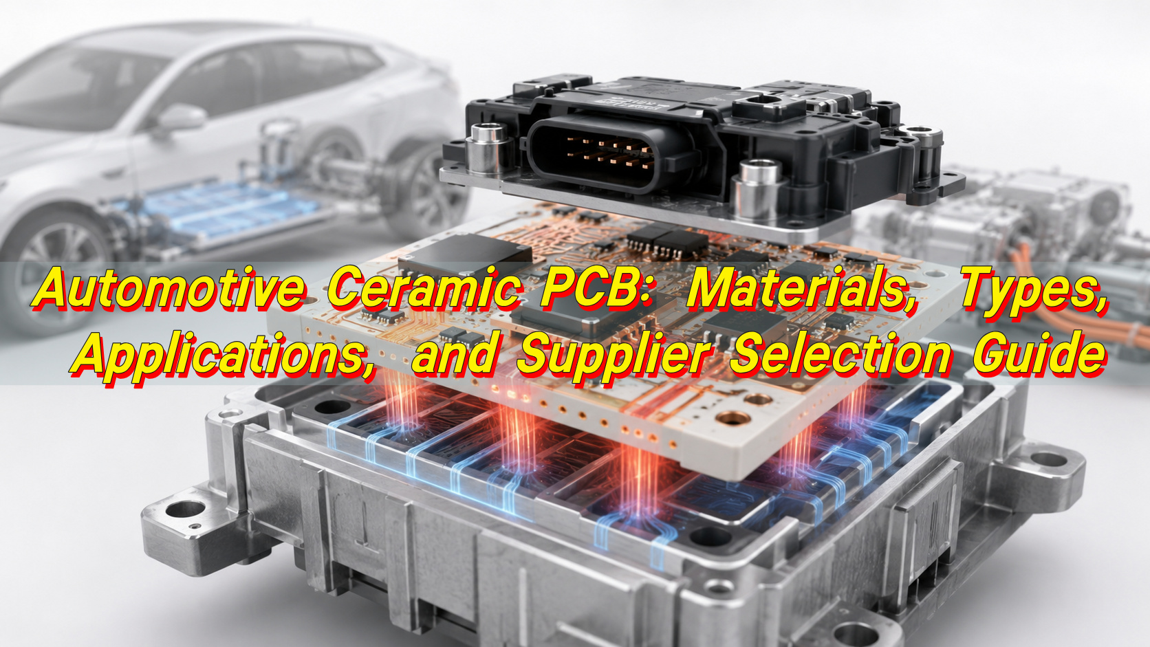
Automotive Ceramic PCB: Materials, Types, Applications, and Supplier Selection Guide
Tuesday, June 9th, 2026

Automotive ceramic PCB technology is used when a vehicle electronic module needs stronger heat dissipation, better insulation, lower thermal expansion, and more stable performance than standard FR4 can provide. In electric vehicles, ADAS systems, LED headlights, battery control units, power modules, sensors, and high-current automotive PCB components, the circuit board is no longer just a connection carrier. It becomes part of the thermal path, electrical insulation system, and long-term reliability structure.

Automotive Ceramic PCB: Materials, Types, Applications, and Supplier Selection Guide

What Is an Automotive Ceramic PCB?

An automotive ceramic PCB is a printed circuit board that uses a ceramic substrate instead of conventional fiberglass-reinforced epoxy laminate. Common substrate materials include alumina, aluminum nitride, and silicon nitride. Copper circuitry is formed on the ceramic surface through processes such as DPC, DBC, AMB, thick film, or thin film manufacturing.

In automotive electronics, ceramic PCB is mainly used in modules exposed to heat, high power density, voltage stress, or repeated temperature changes. Typical examples include LED headlight boards, EV power conversion modules, battery-related control circuits, motor drive substrates, sensor modules, ignition-related electronics, and compact power control units.

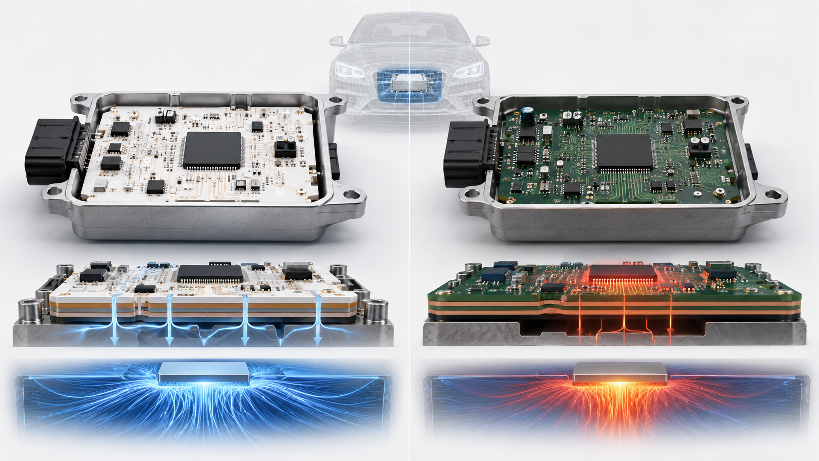
Unlike FR4 PCB, ceramic PCB does not rely on organic resin as the main insulation base. This gives it better dimensional stability at high temperature, stronger thermal conductivity, and a coefficient of thermal expansion closer to many semiconductor materials. That is why many automotive PCB manufacturers use ceramic substrates for mission-critical thermal designs.

Why Are Ceramic PCBs Important in Automotive Electronics?

Modern vehicles contain more electronics than ever. EV platforms, hybrid systems, radar modules, high-brightness lighting, power converters, inverters, charging systems, and smart control units all create heat. At the same time, automotive modules must survive vibration, humidity, temperature cycling, current load, and long service life expectations.

Ceramic PCB helps solve several common automotive design problems:

  • It moves heat away from power devices more efficiently.
  • It provides stable electrical insulation under high voltage.
  • It reduces thermal expansion mismatch between chips, copper, solder, and substrate.
  • It supports compact layouts where heat sinks and thick FR4 structures are not enough.
  • It improves reliability in modules that face repeated heating and cooling.

For buyers, this matters because thermal failure is often expensive. A board that works in a bench test may fail after months of real vehicle use if the substrate, copper thickness, solder joint, and thermal path were not designed together.

How Does an Automotive Ceramic PCB Work?

An automotive ceramic PCB works by combining electrical connection, insulation, and heat transfer in one structure. The ceramic substrate acts as an insulating but thermally conductive base. Copper traces or copper layers carry current and signals. Heat generated by power chips, LEDs, MOSFETs, IGBTs, resistors, or driver ICs is transferred through the copper and ceramic into the heat sink, housing, or cooling system.

Automotive Ceramic PCB: Materials, Types, Applications, and Supplier Selection Guide

The simplified thermal path is:

Heat SourceTransfer LayerMain Function
LED, MOSFET, IGBT, driver IC, resistorCopper circuit layerCurrent path and first heat-spreading layer
Ceramic substrateAlumina, AlN, or Si3N4Electrical insulation and heat transfer
Interface materialSolder, sintered silver, thermal pad, or greaseReduces thermal resistance
Heat sink or housingAluminum, copper, or module bodyFinal heat dissipation structure

The performance depends on the whole stack, not only the ceramic material. A high-thermal-conductivity substrate cannot fully solve the problem if the copper is too thin, the solder layer has voids, the board is warped, or the heat sink contact is poor.

Main Automotive Ceramic PCB Types

Different automotive applications need different ceramic PCB structures. The most common options are DPC, DBC, AMB, thick film, thin film, HTCC, and LTCC.

TypeBest Used ForMain StrengthTypical Limitation
DPC ceramic PCBFine circuits, sensors, LEDs, compact modulesGood circuit precision and plating controlNot ideal for very thick copper power modules
DBC ceramic PCBPower electronics, EV modules, high-current circuitsStrong copper thickness and thermal pathLess suitable for very fine traces
AMB ceramic PCBEV power modules, Si3N4 substrates, high thermal cyclingStrong bonding and mechanical reliabilityHigher cost and stricter process control
Thick film ceramic PCBResistor networks, sensors, hybrid circuitsStable functional films and mature processLimited fine-line capability
Thin film ceramic PCBRF, precision sensors, high-frequency modulesExcellent precision and signal stabilityHigher cost for mass production
HTCCHarsh-temperature and sealed packagesStrong high-temperature structureProcess cycle is longer
LTCCRF, antenna, sensor, multilayer ceramic modulesGood integration and miniaturizationMaterial and process matching are critical

For automotive ceramic PCB selection, DBC and AMB are often considered for power modules, while DPC is more common for LED, sensor, and fine-circuit ceramic boards. Thick film and thin film ceramic PCB are chosen when functional resistive layers, precise metallization, or signal behavior matter.

Ceramic PCB Materials Used in Automotive Applications

Material choice is one of the most important decisions in ceramic PCB design. The substrate affects heat transfer, mechanical strength, cost, thermal expansion, process compatibility, and long-term reliability.

MaterialTypical Thermal ConductivityTypical Use in Automotive ElectronicsSelection Note
Alumina ceramicAbout 20–30 W/m·KLED modules, sensors, moderate-power control boardsCost-effective and widely used
Aluminum nitrideOften 170 W/m·K or higherHigh-power LEDs, EV power modules, laser drivers, compact power boardsStrong thermal performance, higher material cost
Silicon nitrideUsually lower than AlN but mechanically strongAMB power substrates, EV power cycling modulesExcellent strength and thermal shock resistance
Beryllium oxideHigh thermal conductivitySpecial high-performance usesLimited by safety and processing concerns

Alumina is often the practical starting point when cost control matters and the heat load is moderate. Aluminum nitride is preferred when thermal resistance must be reduced in a small space. Silicon nitride is valuable when mechanical robustness, thermal cycling, and copper bonding strength are more important than maximum thermal conductivity alone.

Automotive Ceramic PCB: Materials, Types, Applications, and Supplier Selection Guide

A good ceramic PCB manufacturer should not recommend the most expensive ceramic by default. The better approach is to match the substrate with junction temperature targets, voltage requirements, copper thickness, mounting method, and production volume.

Key Features and Benefits of Automotive Ceramic PCB

Automotive ceramic PCB offers several clear advantages when used in the right place.

BenefitWhy It Matters in Vehicles
High thermal conductivityHelps control LED brightness decay, MOSFET heating, and power module temperature
Electrical insulationSupports compact high-voltage and high-current designs
Low thermal expansionReduces stress between chips, copper, solder, and substrate
High temperature resistancePerforms better than organic boards in hot zones
Good dimensional stabilitySupports accurate assembly and stable module geometry
Strong corrosion resistanceUseful in sealed or harsh-environment electronics
Compact structureHelps reduce module size in EV and smart vehicle systems

The biggest benefit is not only heat dissipation. It is reliability under combined stress. Automotive modules rarely face just one stress factor. They often face heat, vibration, current load, humidity, and assembly pressure at the same time. Ceramic PCB can provide a stronger base for these demanding conditions.

Limitations and Risks You Should Know Before Selection

Ceramic PCB is powerful, but it is not suitable for every automotive board. FR4 is still the better option for many low-power control circuits, infotainment boards, general signal boards, and cost-sensitive modules.

Common limitations include:

  • Higher material and manufacturing cost than FR4
  • Brittleness during handling, routing, assembly, and module mounting
  • Design restrictions for board size, panel utilization, and mechanical holes
  • Longer production cycle for special materials or custom copper thickness
  • Higher requirement for soldering profile, fixture design, and packaging protection
  • Potential copper delamination if material, process, or thermal cycling is poorly controlled

The main mistake is using ceramic PCB as a direct FR4 replacement without redesigning the mechanical and thermal structure. Ceramic boards need careful attention to edge clearance, mounting pressure, copper balance, warpage, solder voids, and thermal interface contact.

Ceramic PCB vs FR4 for Automotive Electronics

Ceramic PCB vs FR4 is one of the most common comparison topics for automotive engineers and buyers. The correct answer depends on the heat load, voltage level, reliability target, cost range, and application zone.

ItemCeramic PCBFR4 PCB
Base materialAlumina, AlN, Si3N4, or other ceramicFiberglass-reinforced epoxy laminate
Thermal performanceMuch higherLimited
Electrical insulationStrongGood for standard applications
High-temperature stabilityStrongDepends on Tg and resin system
Mechanical toughnessBrittle, needs careful handlingBetter flexibility and toughness
Fine multilayer routingPossible but costlierMature and cost-effective
CostHigherLower
Best fitPower, LED, EV, sensor, high-heat modulesGeneral control, communication, logic, low-power boards

Use ceramic PCB when heat, insulation, or thermal cycling is the core reliability issue. Use FR4 when the board mainly handles low-power signals, standard control logic, or cost-sensitive assembly. In many automotive products, both materials can appear in the same system. A power section may use ceramic PCB, while the control section remains FR4.

Where Are Automotive Ceramic PCBs Used?

Automotive ceramic PCB is used across several high-value vehicle electronics areas.

EV power electronics
Ceramic substrates are used in inverters, DC-DC converters, onboard chargers, power modules, and current control circuits. These applications need strong insulation and heat transfer.

LED headlights and lighting modules
High-power LED headlights generate concentrated heat. Ceramic PCB helps keep LED junction temperature under control and supports long-term brightness stability.

Battery management and high-voltage control
Some battery-related circuits need insulation stability, heat resistance, and reliable current handling. Ceramic boards can support compact layouts near high-power zones.

ADAS sensors and radar-related modules
Sensor modules may require stable dimensions, low signal loss, and thermal stability. Thin film or LTCC ceramic solutions may be considered in selected high-frequency or sensor packaging designs.

Engine and transmission control environments
Near-engine electronics face heat and vibration. Ceramic PCB can be used where standard boards may struggle with temperature cycling.

Automotive power resistors and hybrid circuits
Thick film ceramic PCB is useful for resistor networks, hybrid circuits, and compact modules requiring printed resistive elements.

Automotive Ceramic PCB: Materials, Types, Applications, and Supplier Selection Guide

Practical Automotive Case Examples

A useful way to understand ceramic PCB is to look at realistic engineering scenarios.

CaseOriginal ProblemCeramic PCB SolutionResult
LED headlight moduleFR4 board caused high LED temperature and faster lumen decayAlumina or AlN ceramic PCB with optimized copper areaBetter heat spreading and more stable lighting performance
EV power moduleHigh current created hot spots and solder fatigue riskDBC or AMB ceramic substrate with thick copperLower thermal resistance and stronger power cycling reliability
Sensor moduleSignal drift appeared after repeated temperature exposureThin film or precision ceramic substrateImproved dimensional and electrical stability
Compact DC-DC boardLimited space made metal heat sink design difficultAlN ceramic PCB integrated into heat pathHigher power density in a smaller module
High-temperature hybrid circuitOrganic substrate could not support operating zoneThick film ceramic circuitMore stable long-term operation

These cases show one important point: ceramic PCB is selected to solve a specific bottleneck. It should be introduced when the thermal path, insulation demand, or environmental stress makes standard PCB materials less suitable.

Design Guidelines for Automotive Ceramic PCB

A strong automotive ceramic PCB starts with design decisions made before manufacturing. Engineers should not treat ceramic as only a material upgrade. The layout, copper geometry, substrate thickness, component placement, and mechanical mounting all affect reliability.

Key design points include:

  • Place high-heat components close to the main thermal path.
  • Avoid sharp copper corners where stress can concentrate.
  • Keep copper distribution balanced to reduce warpage.
  • Reserve safe edge clearance because ceramic edges are more fragile than FR4.
  • Control hole placement and avoid unnecessary mechanical stress points.
  • Match copper thickness with current load and heat-spreading needs.
  • Review solder pad size carefully to control voiding and wetting.
  • Define voltage clearance based on working voltage and pollution environment.
  • Confirm mounting torque, screw position, and support structure early.
  • Use DFM review before prototype production.

For automotive projects, the drawing should clearly specify substrate material, copper thickness, board thickness, surface finish, tolerance, flatness, test requirements, and packaging method. Missing details can create serious problems when the project moves from sample development to batch production.

Manufacturing Process Considerations

Automotive ceramic PCB manufacturing requires tighter process control than standard FR4 PCB. The right process depends on the required copper thickness, line width, substrate type, and reliability target.

DPC process usually involves ceramic cleaning, seed layer deposition, imaging, copper plating, etching, solder mask or protective layer, surface finish, profiling, and final testing. It is suitable for fine circuits and medium copper thickness.

DBC process bonds copper directly to ceramic under high temperature. It is often used for power substrates with thicker copper and strong thermal transfer.

AMB process uses active brazing material to bond copper and ceramic, especially for silicon nitride substrates. It is suitable for high-reliability power modules and harsh thermal cycling conditions.

Thick film process prints conductive, resistive, or dielectric paste on ceramic and fires it at high temperature. It is useful for hybrid circuits and functional layers.

Thin film process uses vacuum deposition and photolithography for very precise circuits. It is common in high-frequency, sensor, and precision electronic modules.

Manufacturing quality depends on ceramic surface preparation, copper adhesion, plating uniformity, sintering or bonding control, etching accuracy, flatness, edge quality, and final cleaning. For automotive applications, process stability is often more important than a single impressive parameter.

Testing Methods and Quality Control

Automotive ceramic PCB quality control should cover electrical, thermal, mechanical, and visual reliability. A simple open-short test is not enough for critical vehicle modules.

Common testing and inspection items include:

Test or InspectionPurpose
Electrical open-short testConfirms basic circuit continuity and isolation
Hi-pot testChecks insulation under high voltage
AOIDetects line defects, scratches, contamination, and pattern issues
X-ray inspectionReviews voids, bonding, or internal defects in selected assemblies
Thermal cycling testEvaluates stress under repeated temperature changes
Copper adhesion testChecks bonding strength between copper and ceramic
Warpage and flatness measurementSupports stable assembly and heat sink contact
Microsection analysisReviews copper thickness, plating quality, and interface structure
Ionic contamination testHelps reduce corrosion and leakage risk
Final visual inspectionChecks edge cracks, chipping, stains, and surface defects

For automotive PCB suppliers, quality control should also include lot traceability, material certificates, process records, inspection reports, and controlled packaging. This is especially important for OEM, ODM, and batch production projects where repeatability matters more than one successful prototype.

Common Failure Modes and Factory-Level Prevention

Automotive ceramic PCB failures usually come from the interaction of material, design, assembly, and operating stress.

Failure ModeCommon CausePrevention Method
Ceramic crackingExcess mounting force, poor fixture support, edge impactControl torque, improve panel handling, add support structure
Copper delaminationWeak bonding, thermal shock, poor material matchSelect proper DBC/AMB/DPC process and verify adhesion
Solder joint fatigueCTE mismatch and repeated thermal cyclingOptimize pad design, solder profile, and component placement
Hot spotsPoor thermal path or insufficient copper areaImprove copper spreading, substrate selection, and heat sink contact
Insulation breakdownContamination, insufficient clearance, high voltage stressImprove cleaning, spacing, coating, and hi-pot testing
WarpageUnbalanced copper, process stress, thin substrateBalance copper and control firing/bonding process
Surface contaminationPoor cleaning or packagingAdd cleanliness inspection and vacuum or dry packaging

A strong ceramic PCB manufacturer should be able to discuss these failure modes before production, not only after defects appear. For automotive projects, prevention is always cheaper than field failure analysis.

Cost Factors in Automotive Ceramic PCB

Automotive ceramic PCB cost is affected by material, board size, copper thickness, process type, tolerance, surface finish, test requirements, and order volume.

Main cost drivers include:

  • Ceramic material: AlN and Si3N4 usually cost more than alumina.
  • Process type: AMB and thin film are generally more expensive than basic alumina DPC.
  • Copper thickness: thicker copper increases material and processing difficulty.
  • Circuit precision: fine lines and tight spacing require stricter control.
  • Board size: larger ceramic panels are harder to process and protect.
  • Surface finish: ENIG, ENEPIG, silver, and other finishes affect cost.
  • Testing level: thermal cycling, hi-pot, cross-section, and reliability tests add cost.
  • Yield risk: complex structures and tight tolerances may reduce production yield.
  • Packaging: automotive ceramic boards need stronger protection during shipping.

The best cost strategy is not to choose the cheapest substrate. It is to define the real working conditions and avoid over-specification. For example, alumina may be enough for a moderate-power LED board, while AlN may be necessary for a compact high-power module. Using AlN where alumina is sufficient increases cost without adding meaningful value.

How to Choose a Ceramic PCB Manufacturer for Automotive Projects?

Choosing a ceramic PCB manufacturer is not only about unit price. Automotive projects need engineering support, process stability, documentation, and repeatable quality.

A qualified supplier should be able to support:

  • Alumina, aluminum nitride, and selected silicon nitride ceramic substrates
  • DPC, DBC, AMB, thick film, or other suitable manufacturing processes
  • Prototype development and batch production transfer
  • Material traceability and incoming inspection
  • Copper thickness verification and adhesion testing
  • Hi-pot, AOI, dimensional, and flatness inspection
  • Engineering DFM review before production
  • Controlled packaging for fragile ceramic substrates
  • Clear communication on tolerances, lead time, and process limits
  • OEM and ODM custom project support
  • Global shipping from a real China source factory without false local claims

For overseas buyers, especially in North America and Europe, the supplier should understand compliance documentation, automotive quality expectations, RoHS/REACH material control, and long-term repeat orders. For Southeast Asian and emerging markets, flexible MOQ, stable lead time, and cost-performance balance may be more important. In both cases, transparent engineering communication is more valuable than a low quotation with unclear process details.

RFQ Checklist Before Placing an Order

Before requesting a quotation, prepare a complete technical package. This helps the supplier give a more accurate price and reduces sample risk.

RFQ ItemWhy It Matters
Gerber filesDefines circuit pattern
BOM and assembly drawing if PCBA is neededHelps review component and soldering requirements
Substrate materialDetermines thermal and mechanical performance
Ceramic thicknessAffects strength, insulation, and heat transfer
Copper thicknessAffects current capacity and heat spreading
Surface finishAffects solderability, bonding, and storage life
Working voltage and currentHelps define clearance, insulation, and copper design
Operating temperature rangeSupports thermal reliability review
Thermal target or power lossHelps select alumina, AlN, or Si3N4
Quantity and forecastAffects process planning and cost
Test requirementsClarifies quality control level
Packaging requirementPrevents ceramic damage during shipment

If your project is still in early development, share the application environment and expected power level first. A responsible ceramic PCB supplier can help narrow the material and process direction before the final drawing is frozen.

Frequently Asked Questions About Automotive Ceramic PCB

What is an automotive ceramic PCB used for?
An automotive ceramic PCB is used in vehicle electronic modules that need strong heat dissipation, electrical insulation, and long-term reliability. Common applications include EV power modules, LED headlights, DC-DC converters, battery-related circuits, sensors, high-power control boards, and hybrid electronic modules.

Is ceramic PCB better than FR4 for automotive electronics?
Ceramic PCB is better when the main challenge is heat, high voltage, thermal cycling, or compact power density. FR4 is still better for many low-power signal and control boards because it is lower cost, easier to process, and more flexible for multilayer routing.

Which ceramic material is best for automotive PCB?
There is no single best material for every automotive project. Alumina is cost-effective for moderate heat. Aluminum nitride is better for high thermal conductivity. Silicon nitride is useful when mechanical strength and thermal shock resistance are critical, especially in demanding power modules.

What is the difference between DPC and DBC ceramic PCB?
DPC ceramic PCB is better for fine circuits, plated copper control, and compact modules. DBC ceramic PCB is better for thicker copper and high-power thermal paths. For automotive power electronics, DBC is often considered when current and heat load are higher.

When should I choose AMB ceramic PCB?
AMB ceramic PCB is often selected for high-reliability power modules, especially when silicon nitride substrates are used. It offers strong bonding performance and good thermal cycling resistance, making it suitable for EV power modules and harsh automotive environments.

Can ceramic PCB be used for automotive LED headlights?
Yes. Ceramic PCB is widely used in high-power automotive LED lighting because it helps transfer heat away from LED chips. Better thermal control can support stable brightness, longer service life, and more compact headlight module design.

Why is automotive ceramic PCB more expensive than FR4?
Ceramic substrates cost more than FR4 laminates, and the manufacturing process is more specialized. Cost also increases with AlN or Si3N4 material, thick copper, fine lines, tight tolerances, surface finish requirements, and automotive-level testing.

Does ceramic PCB crack easily?
Ceramic PCB is more brittle than FR4, so it needs careful handling, proper packaging, controlled mounting force, and good fixture design. With correct mechanical design and production control, ceramic boards can perform reliably in demanding automotive applications.

What tests are important for automotive ceramic PCB?
Important tests include open-short testing, hi-pot insulation testing, AOI, copper adhesion testing, flatness measurement, thermal cycling, dimensional inspection, and microsection analysis when needed. For high-reliability modules, test requirements should be confirmed before production.

Can ceramic PCB support high-current automotive components?
Yes, especially when DBC or AMB structures with thicker copper are used. Current capability depends on copper thickness, trace width, substrate material, thermal path, operating temperature, and heat sink design. The board should be reviewed together with the full module structure.

How do I choose between alumina and aluminum nitride?
Choose alumina when cost control matters and the heat load is moderate. Choose aluminum nitride when the design needs much better thermal conductivity in a compact space. The decision should be based on power loss, junction temperature target, board size, and total thermal resistance.

What information should I send to a ceramic PCB supplier?
Send Gerber files, substrate material, copper thickness, ceramic thickness, surface finish, working voltage, current load, operating temperature, quantity, testing needs, and application details. If the design is not finalized, share the thermal and mechanical requirements first.

Can a China ceramic PCB manufacturer support global automotive projects?
Yes, if the manufacturer has real ceramic PCB production capability, material traceability, engineering review, quality documentation, stable process control, and global shipping experience. Buyers should verify capabilities instead of relying only on price or generic supplier claims.

What is the biggest design mistake with automotive ceramic PCB?
The biggest mistake is replacing FR4 with ceramic without redesigning the thermal and mechanical structure. Ceramic PCB requires proper copper balance, edge clearance, mounting support, soldering control, and heat sink contact. Material selection alone cannot guarantee reliability.

Conclusion:

Automotive ceramic PCB is not a universal replacement for FR4, but it is one of the most effective solutions for vehicle modules where heat, high voltage, compact power density, and thermal cycling are the main design challenges. Alumina offers a practical cost-performance balance. Aluminum nitride supports stronger heat dissipation. Silicon nitride and AMB structures are valuable for demanding power cycling environments.

For engineering selection, start from the application conditions: power loss, operating temperature, voltage, available space, mounting structure, reliability target, and expected production volume. For procurement, focus on process capability, quality control, testing support, traceability, and whether the supplier can transfer prototypes into stable batch production.

As a China source factory and global ceramic PCB manufacturer, EBest Circuit(Best Technology) supports custom ceramic PCB development, OEM manufacturing, ODM production, prototype builds, and batch production for automotive and industrial electronics projects. If you need technical support, material selection advice, cost evaluation, or a quotation for your automotive ceramic PCB project, please contact our engineering team at sales@bestpcbs.com.

You may also like

Automotive AMB Ceramic PCB Fabrication: What Should Customers Know?
Wednesday, May 20th, 2026

Automotive AMB ceramic PCB fabrication has become a critical topic as electric vehicles, hybrid vehicles, onboard chargers, traction inverters, DC DC converters, and high power automotive control systems continue to move toward higher current density, higher working temperature, and smaller module size. For customers, this subject is not only about choosing a ceramic board. It is about selecting a power substrate structure that can help manage heat, support electrical insulation, carry heavy current, and remain stable under long term thermal cycling.

Automotive AMB Ceramic PCB Fabrication: What Should Customers Know?

EBest Circuit (Best Technology) supports customers who need engineering driven ceramic PCB manufacturing, including ceramic material evaluation, DFM review, copper pattern optimization, surface finish selection, fabrication control, and production quality documentation.

What Is an AMB Ceramic Substrate?

An AMB ceramic substrate is a metallized ceramic substrate made by bonding copper to a ceramic base through active metal brazing. “AMB” stands for Active Metal Brazing. In this process, a brazing filler containing active elements, often titanium based, forms a strong metallurgical bond between the copper layer and the ceramic material. The result is a substrate that combines the high electrical conductivity of copper with the high insulation strength and heat resistance of ceramic.

In a typical AMB ceramic substrate, the ceramic core may be silicon nitride, aluminum nitride, or another suitable ceramic material. For demanding automotive power modules, silicon nitride is widely valued because it offers strong mechanical toughness and good thermal performance. Aluminum nitride is also attractive where high thermal conductivity is a leading design requirement.

Unlike FR4 PCB or standard metal core PCB, an AMB ceramic substrate is designed for power density and thermal stress. It is not simply a board with better heat dissipation. It is a structural part of the power module. The substrate may need to handle fast switching, high voltage isolation, solder layer stress, thermal expansion mismatch, and repeated heating and cooling during vehicle operation. That is why AMB ceramic is often selected for electric vehicle traction inverter modules, onboard chargers, high voltage DC DC modules, and other high reliability automotive PCB components.

What is automotive AMB ceramic PCB fabrication?

Automotive AMB ceramic PCB fabrication refers to the controlled manufacturing of AMB ceramic substrates for automotive power electronics. It includes ceramic material selection, copper bonding, pattern imaging, copper etching, plating, surface finishing, inspection, and reliability related process control.

In practical terms, automotive AMB ceramic PCB fabrication is more demanding than ordinary PCB fabrication because the product is used in a harsher environment. A vehicle may experience cold starts, high ambient temperature, vibration, load cycling, humidity, and long operating hours. In electric vehicle power systems, the AMB substrate may sit directly under power semiconductor chips. It must move heat from the chip to the cooling structure while maintaining dielectric isolation between the high voltage circuit and the baseplate or cooling system.

Automotive AMB Ceramic PCB Fabrication: What Should Customers Know?

A customer usually needs to define several project details before fabrication starts. These include ceramic type, ceramic thickness, copper thickness, copper pattern tolerance, isolation voltage, partial discharge target, surface finish, solderability requirement, module layout, and assembly process.

For EBest Circuit (Best Technology), the engineering value lies in helping customers review whether the design is manufacturable and whether the substrate structure is aligned with the module’s real use conditions.

What makes an AMB ceramic substrate different from standard PCBs?

An AMB ceramic substrate is different from a standard PCB in material system, bonding method, thermal behavior, current carrying ability, and long term reliability expectation. A standard FR4 PCB uses woven glass reinforced epoxy as the insulating core. It is excellent for signal circuits, control electronics, and many general applications.

Metal core PCBs can improve thermal dissipation compared with FR4, especially in LED lighting and moderate power electronics. Even so, the dielectric layer in a metal core PCB often becomes the thermal bottleneck. AMB ceramic substrates use ceramic as the insulating and heat conducting layer, so they offer a stronger combination of thermal transfer, insulation, and mechanical strength for power modules.

ItemAMB Ceramic SubstrateStandard FR4 PCBMetal Core PCB
Main insulation materialCeramic such as Si₃N₄ or AlNEpoxy glass laminatePolymer dielectric over metal base
Copper structureThick copper bonded to ceramicCopper foil laminated to FR4Copper foil over dielectric layer
Main advantageHigh power density, strong insulation, good heat pathCost efficient and versatileBetter heat spreading than FR4
Typical useAutomotive power modules, inverter modules, SiC/IGBT modulesControl boards, signal boards, low to medium power electronicsLED boards, power supply boards, thermal interface boards
Thermal pathChip to copper to ceramic to cooling systemChip to copper to FR4, often with viasChip to copper to dielectric to metal base
Mechanical concernCeramic and copper stress balanceLaminate expansion, via reliabilityDielectric aging and thermal resistance
Automotive relevanceStrong fit for high voltage power modulesStrong fit for control and communication boardsUseful for thermal boards with moderate power density

The difference becomes clear when you look at system level performance. A standard PCB usually supports electronic interconnection. An AMB ceramic substrate supports interconnection, insulation, heat transfer, and module reliability at the same time.

What thermal conductivity requirements for automotive AMB PCB?

Thermal conductivity requirements for an automotive AMB PCB depend on the semiconductor device, power loss, chip size, cooling method, ceramic material, copper thickness, and target junction temperature. There is no universal value that fits every power module.

In many automotive power modules, the design target is to move heat away from the chip as quickly and evenly as possible. The substrate must reduce hot spots, support stable solder or sintered silver layers, and help maintain a safe junction temperature during load cycling. A high thermal conductivity ceramic can improve heat flow, but thickness, copper coverage, void control, and interface quality also influence the final result.

For customers, it is useful to evaluate thermal requirements through several connected factors:

  • Power loss per chip: Higher switching and conduction losses require a stronger heat path.
  • Chip technology: SiC devices often support high power density and high temperature operation, so substrate design must keep pace.
  • Ceramic material: AlN usually offers excellent thermal conductivity, while Si₃N₄ offers a strong balance of thermal performance and mechanical toughness.
  • Ceramic thickness: Thicker ceramic improves insulation margin but may raise thermal resistance.
  • Copper thickness and layout: Thick copper improves current capacity and heat spreading, but it also increases mechanical stress.
  • Cooling method: Liquid cooled modules, baseplate structures, and direct cooling designs all change the thermal calculation.

EBest Circuit can support early review of ceramic PCB stack up, copper layout, and process feasibility so that the final AMB ceramic substrate is easier to manufacture and more suitable for the automotive module.

What Automotive PCB Components Use AMB Ceramic Substrates?

AMB ceramic substrates are mainly used in automotive PCB components that handle high voltage, high current, and high temperature. They are especially common in power conversion and motor drive systems where semiconductor chips generate concentrated heat.

Automotive AMB Ceramic PCB Fabrication: What Should Customers Know?

Typical automotive applications include:

  • Traction inverter power modules used in electric vehicle motor control.
  • Onboard charger modules that convert AC input into DC battery charging power.
  • High voltage DC DC converter modules used to step voltage between battery systems and auxiliary systems.
  • Electric compressor inverter modules for EV thermal management systems.
  • Battery management and power distribution modules where high voltage insulation and thermal control are required.
  • SiC MOSFET and IGBT power modules used in high efficiency switching systems.
  • Power control units that combine several automotive power conversion functions.

Why do modern automotive power modules require AMB technology?

Modern automotive power modules require AMB technology because EV power systems are becoming smaller, faster, hotter, and more power dense.

Another reason is insulation. In high voltage EV systems, the substrate must separate live power circuits from the cooling structure or baseplate. Ceramic materials provide strong dielectric properties, and the copper pattern can be designed for creepage and clearance needs. When the module operates in a vehicle, insulation quality must remain stable through temperature change and humidity exposure. That makes material choice and manufacturing control very important.

AMB is also useful for thermal expansion management. Power modules contain many materials, including silicon or silicon carbide chips, solder or sinter layers, copper, ceramic, baseplate materials, and encapsulants. Each material expands differently during temperature change. Silicon nitride AMB substrates are often selected when mechanical toughness and thermal cycling reliability are important. The copper to ceramic bond created by active metal brazing helps the substrate withstand repeated stress when the design is properly balanced.

How does AMB compare directly to traditional DBC (Direct Copper Bonding)?

AMB and DBC are both ceramic substrate technologies used in power electronics. Both use copper and ceramic to create a thermally conductive, electrically insulating circuit carrier. The main difference is the bonding method. AMB uses an active metal brazing layer to join copper and ceramic. DBC uses a high temperature bonding process that relies on copper oxide interaction with oxide ceramic surfaces.

DBC remains valuable in many power applications. It is mature, cost effective, and well suited for alumina and aluminum nitride ceramic systems. AMB becomes especially attractive when the project requires silicon nitride ceramic, higher mechanical robustness, stronger thermal cycling capability, or a substrate structure designed for demanding automotive power modules.

Comparison ItemAMB Ceramic SubstrateDBC Ceramic Substrate
Full nameActive Metal BrazingDirect Bonded Copper
Bonding principleActive metal brazing layer bonds copper to ceramicCopper is directly bonded to ceramic through a high temperature process
Common ceramic choicesSi₃N₄, AlN, and selected ceramic systemsAl₂O₃, ZTA, AlN, and oxide based ceramic systems
Strength in automotive useStrong fit for high reliability power modules and thermal cyclingMature option for many power electronic modules
Mechanical toughnessOften excellent with Si₃N₄ ceramicDepends strongly on ceramic material
Thermal performanceStrong, depending on ceramic and structureStrong, especially with AlN based DBC
Cost tendencyUsually higher due to process complexityOften more economical for suitable applications
Design flexibilitySuitable for thick copper and demanding module layoutsSuitable for many proven power substrate layouts
Best fitEV traction inverter, SiC module, high reliability automotive moduleGeneral power modules, industrial power electronics, cost sensitive designs

The choice between AMB and DBC should not be made by trend alone. A well designed DBC substrate can perform very well in the right application. A well designed AMB substrate can provide a stronger reliability margin in high stress automotive power modules. The better decision comes from comparing power loss, operating voltage, expected temperature swing, module lifetime target, ceramic choice, copper thickness, and qualification plan.

For customers working with EBest Circuit, the practical approach is to share the operating condition, target module structure, and reliability expectation. Then the engineering team can help review whether AMB ceramic, DBC ceramic, or another PCB technology provides the best balance of performance, manufacturability, and cost.

What are the key steps in the AMB ceramic manufacturing process?

The AMB ceramic manufacturing process requires careful control because each step can affect bonding strength, insulation quality, copper pattern accuracy, and final module reliability.

The main steps usually include:

  • Material selection and incoming inspection: The process begins with ceramic sheets and copper foils or copper plates. The ceramic material, thickness, flatness, surface condition, and mechanical quality must match the project requirement.
  • Surface preparation: Ceramic and copper surfaces are cleaned and prepared to support strong brazing. Contamination, oxidation condition, and surface roughness must be controlled.
  • Active metal brazing: Copper is bonded to the ceramic using an active brazing material under a controlled high temperature process. This step forms the metallurgical interface between copper and ceramic.
  • Copper pattern formation: After bonding, the copper layer is imaged and etched to create circuit patterns, power pads, chip attach areas, and connection features.
  • Surface finishing: Depending on the assembly process, the substrate may receive nickel plating, gold plating, silver plating, or another suitable surface finish.
  • Solder mask or protective coating when required: Some designs need protective areas or defined solderable regions. The process must remain compatible with high power module assembly.
  • Dimensional and visual inspection: Copper geometry, edge quality, pattern accuracy, surface condition, and ceramic integrity are checked.
  • Electrical and reliability related testing: Tests may include dielectric withstand, insulation resistance, partial discharge evaluation, peel strength, solderability, and thermal related checks depending on project needs.

In automotive AMB ceramic PCB fabrication, the manufacturing process must be stable and repeatable. Small changes in surface condition, brazing uniformity, etching quality, or plating thickness may affect downstream assembly.

This is why customers should treat AMB ceramic production as an engineering process rather than a simple purchase order. EBest Circuit supports communication between customer engineering, production, and quality teams so that drawings, tolerances, testing items, and delivery expectations are aligned before fabrication begins.

How to ensure AQG324 compliance in AMB fabrication?

AQG324 compliance starts with understanding that the guideline is mainly focused on qualification of automotive power modules, not only the bare ceramic substrate. However, the AMB substrate plays a central role in module reliability, so substrate fabrication must support the final module qualification plan.

For AMB fabrication, the customer and supplier should connect substrate requirements with module level qualification targets. This means the bare substrate drawing should not only show dimensions and copper patterns. It should also define critical items that influence the final AQG324 test result, such as ceramic material, copper thickness, plating structure, dielectric performance, partial discharge expectation, void control, peel strength, and traceability.

Automotive AMB Ceramic PCB Fabrication: What Should Customers Know?

A practical AQG324 aligned approach may include the following actions:

  • Define the automotive use condition early. The supplier needs to know whether the substrate will be used in a traction inverter, onboard charger, DC DC converter, or another module type.
  • Confirm ceramic and copper structure. Material selection should support thermal resistance, insulation voltage, mechanical reliability, and cycling demand.
  • Control process parameters. Brazing, etching, plating, cleaning, and inspection must follow stable and documented process windows.
  • Build traceability. Material lot, production batch, process records, inspection data, and shipment records should be retained in a controlled way.
  • Use proper reliability screening. Depending on project requirement, this may include thermal cycling, power cycling support data, dielectric withstand, insulation resistance, partial discharge, and peel strength testing.
  • Align with module assembly needs. Substrate flatness, surface finish, solderability, bonding surface, and cleanliness must support soldering, sintering, wire bonding, or clip bonding processes.
  • Document deviations clearly. Any material change, process change, or supplier change should be controlled through a formal change management process.

The power module manufacturer usually completes module level AQG324 qualification because final performance depends on the complete module structure, including chips, die attach, interconnects, encapsulation, cooling, and housing.

EBest Circuit helps customers prepare AMB ceramic PCB manufacturing data in a way that supports automotive review. That includes DFM feedback, drawing review, process feasibility comments, material and finish discussion, and quality documentation support.
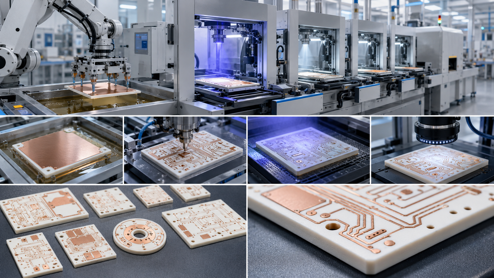
What Design Factors Affect AMB Ceramic PCB Performance?

Several design factors affect AMB ceramic PCB performance, and many of them are connected. A strong AMB substrate design balances heat transfer, insulation, current carrying ability, manufacturability, and mechanical reliability. If one factor is pushed too far, another factor may suffer.

The first factor is ceramic material. Silicon nitride is often selected for high reliability automotive modules because it provides strong mechanical toughness and good thermal performance. Aluminum nitride is attractive when thermal conductivity is the leading concern. Alumina and zirconia toughened alumina are also used in many ceramic substrate applications.

The second factor is ceramic thickness. A thinner ceramic layer can improve heat transfer, while a thicker layer can support higher insulation requirements. In automotive power modules, the decision should be based on working voltage, isolation test target, partial discharge behavior, and safety margin.

The third factor is copper thickness and copper balance. Thick copper supports high current and better heat spreading. However, copper and ceramic expand at different rates. If the copper pattern is unbalanced between the top and bottom sides, the substrate may warp or carry uneven stress.

The fourth factor is copper pattern geometry. Sharp corners, narrow necks, isolated heavy copper islands, and abrupt width changes may create stress concentration or current crowding. In high voltage designs, copper spacing, creepage, clearance, and edge radius also affect insulation behavior.

The fifth factor is surface finish. The finish must match the assembly process. Nickel gold, nickel silver, and other finishes may be considered based on soldering, sintering, wire bonding, storage life, and customer assembly conditions.

The sixth factor is module level thermal design. AMB ceramic works best when the whole heat path is engineered properly. The path may include chip attach material, top copper, ceramic, bottom copper, solder layer, baseplate, thermal interface material, and cooler.

The seventh factor is manufacturability. A drawing with very tight tolerances, complex copper shapes, or aggressive spacing may increase cost and production difficulty. Early DFM review can help the customer adjust the design without weakening performance. EBest Circuit (Best Technology) supports this stage by reviewing ceramic PCB drawings, copper geometry, surface finish needs, and inspection requirements before production.

In brief, automotive AMB ceramic PCB fabrication should be treated as a system level engineering decision. The best result comes from matching AMB ceramic material, copper structure, thermal design, insulation target, process control, and automotive quality documentation. For customers developing automotive power modules, EBest Circuit (Best Technology) can support ceramic PCB fabrication, DFM review, material discussion, process control, and production quality support from prototype to batch production. For project evaluation or technical discussion, contact sales@bestpcbs.com

You may also like

Top Automotive MCPCB Supplier: IATF16949 & AEC-Q200 Qualified
Thursday, April 23rd, 2026

As a professional Automotive MCPCB supplier, EBest delivers high-performance automotive MCPCBs with thermal conductivity up to 3.0 W/m.K, full automotive-grade certifications, and reliable adaptation to the extreme high-temperature, high-vibration automotive environments. With over 19 years of experience, we solve your core pain points and provide one-stop, reliable solutions for automotive electronic projects.

Top Automotive MCPCB Supplier: IATF16949 & AEC-Q200 Qualified

Why Choose EBest as Your Trusted Automotive MCPCB Supplier?

EBest is the preferred Automotive MCPCB supplier for global automotive electronic enterprises, with core parameters and advantages that fully meet automotive industry demands. Our automotive MCPCBs support 1–10 layers, with thermal conductivity ranging from 0.8~3.0 W/m.K, dielectric strength exceeding 3.0 Kv (L/S >3.0mm), and compliance with all automotive-grade standards. Contact us today to place your order and get customized solutions tailored to your project.
Why Choose Our Automotive MCPCB Supplier Services?

  • Quality: We implement full-process quality control, from raw material selection to finished product delivery, with 100% full inspection to ensure product consistency and reliability, meeting the strict requirements of automotive electronic applications.
  • Lead Time: Our monthly production capacity reaches 260,000 square feet, with an expedited service that allows urgent automotive MCPCB orders to be shipped within 24 hours, ensuring your project progress is not delayed.
  • Service: We provide one-stop services, including custom substrate selection, design optimization, prototype production, and mass production, with a professional technical team to provide real-time support throughout the project.
  • Supply Chain: We have a stable, comprehensive supply chain for electronic components and MCPCB raw materials, ensuring continuous production and avoiding supply chain risks that affect your orders.

What Are the Core Services and Qualification Certifications of EBest Automotive MCPCB Supplier?

Qualification CertificationsPractical Value for Automotive MCPCB Applications
IATF 16949The exclusive quality management system certification for the automotive industry, ensuring full-process controllable production of automotive MCPCBs and eliminating quality hazards.
ISO 9001:2015Standardizes our production and service processes, ensuring consistent quality of automotive MCPCBs in mass production.
ISO 13485:2016Meets the quality requirements for automotive medical-grade electronic components, suitable for high-reliability automotive MCPCB applications.
AS9100DEnsures our automotive MCPCBs have high reliability and stability, adapting to the harsh working environment of automotive electronic systems.
REACHComplies with European environmental standards, ensuring our automotive MCPCBs are environmentally friendly and meet international export requirements.
RoHSRestricts harmful substances in automotive MCPCBs, ensuring product safety and compliance with global automotive environmental regulations.
ULCertifies the safety performance of our automotive MCPCBs, ensuring they can operate stably in high-temperature, high-voltage automotive environments.

In addition to the above certifications, EBest, as a professional Automotive MCPCB supplier, provides a full range of services including PCB Fabrication, Component Sourcing, BGA Assembly, Flex PCB Assembly, and Injection Molding, covering the entire automotive MCPCB production and supporting process.

What Pain Points Do Automotive MCPCB Users Face, and How Does EBest Solve Them?

Many users encounter various challenges when selecting and using automotive MCPCBs, and EBest, as an experienced Automotive MCPCB supplier, has targeted solutions for each pain point.

  • Pain Point 1: Poor Thermal Conductivity Leading to Short Product Life

Automotive MCPCBs in LED headlights, BMS systems, and motor controllers generate significant heat during operation. Poor thermal conductivity can cause overheating and shorten service life.

Our Solution: We offer automotive MCPCBs with high thermal conductivity (up to 3.0 W/m.K), which is 2–3 times higher than ordinary MCPCBs. This effectively reduces component junction temperature and extends product service life by 50% or more.

  • Pain Point 2: Quality Instability Affecting Automotive Safety

Inconsistent product quality during mass production can lead to automotive electronic failures, posing safety risks and damaging brand reputation.

Our Solution: We adopt fully automatic assembly equipment and more than 19 quality inspection processes, with IATF 16949 certification to ensure each automotive MCPCB meets strict quality standards, with a pass rate of over 99.7%.

  • Pain Point 3: Long Lead Time Delaying Project Progress

Many suppliers cannot meet urgent order requirements, leading to project delays and increased costs for users.

Our Solution: With a monthly production capacity of 260,000 square feet, we provide 24-hour expedited service for urgent automotive MCPCB orders, ensuring timely delivery and supporting your project progress.

  • Pain Point 4: Lack of Customization Capabilities for Special Requirements

Automotive electronic projects have diverse requirements for MCPCB thickness, size, and surface treatment, which many suppliers cannot fulfill.

Our Solution: We provide full customization services, supporting board thickness from 0.3mm to 4.0mm, a maximum board size of 610*1625mm, and multiple surface treatments (ENIG, HAL, OSP, etc.) to meet your specific project needs.

Choose EBest as your Automotive MCPCB supplier, and we will solve all your pain points with professional technology and reliable service. Contact us now to start your customized project.

Top Automotive MCPCB Supplier: IATF16949 & AEC-Q200 Qualified

FAQ: Common Questions About Automotive MCPCB Supplier Services

  • Q1: What thermal conductivity options does EBest’s Automotive MCPCB supplier provide?

EBest, as a professional Automotive MCPCB supplier, provides two types of thermal conductivity options: normal (0.8~1.0, 1.5 W/m.K) and high (2.0, 3.0 W/m.K). You can choose based on your automotive electronic application scenario and heat dissipation needs.

  • Q2: Can EBest’s Automotive MCPCB meet the high-temperature requirements of automotive environments?

Yes. Our automotive MCPCBs can withstand thermal stress of 3 x 10 Sec @ 280 ℃, with a flammability rating of 94V-0, and can operate stably in the high-temperature environment near automotive engines and battery packs (up to 150℃ for long-term use).

  • Q3: Does EBest provide prototype production for automotive MCPCBs?

Yes. We provide prototype PCB assembly services for automotive MCPCBs, supporting small-batch prototype production, and can complete prototype samples in a short time to help you verify design schemes quickly.

  • Q4: What is the maximum layer count of EBest’s automotive MCPCBs?

As a professional Automotive MCPCB supplier, we can produce automotive MCPCBs with a maximum layer count of 10 layers, which can meet the complex wiring needs of automotive electronic control units (ECUs) and ADAS systems.

  • Q5: How does EBest ensure the supply chain stability of automotive MCPCBs?

We have a dedicated purchasing team and a stable supply chain for electronic components and MCPCB raw materials, covering SMD, BGA, QFN, QFP, and other components. This ensures continuous production and avoids supply chain disruptions.

  • Q6: Can EBest’s automotive MCPCBs meet international export standards?

Yes. Our automotive MCPCBs have passed REACH, RoHS, UL, and other international certifications, complying with the environmental and safety standards of European, American, and other global markets, and can be directly exported.

  • Q7: What surface treatment options are available for EBest’s automotive MCPCBs?

We provide a variety of surface treatment options, including ENIG, Flash Gold, Hard Gold Finger, Gold Plating, ENEPIG, ENIPIG, HAL, HASL(LF), OSP, Silver Immersion, and Tin Immersion, to meet different automotive application requirements.

What Is the Application of EBest’s Automotive MCPCBs in the Automotive Electronics Industry?

EBest’s automotive MCPCBs are widely used in various automotive electronic scenarios, with practical cases proving their reliability and performance advantages.

Case 1: Automotive LED Headlight MCPCB Solution

A global automotive lighting manufacturer faced the problem of short LED life due to poor heat dissipation of ordinary MCPCBs. The LED chip junction temperature reached 160℃, and the service life was far below expectations.

We provided high thermal conductivity (3.0 W/m.K) automotive MCPCBs, optimizing the heat dissipation structure. After replacement, the chip junction temperature was stabilized below 110℃, and the LED service life was extended by 60%, fully meeting the manufacturer’s requirements.

Case 2: Automotive BMS System MCPCB Solution

A new energy vehicle manufacturer needed MCPCBs with high dielectric strength and stable performance for their BMS systems to avoid short circuits and safety hazards caused by voltage fluctuations.

Our automotive MCPCBs have a dielectric strength of over 3.0 Kv (L/S >3.0mm), with a double insulation structure design. This effectively prevents short circuits and ensures the stable operation of the BMS system in high-voltage environments.

How to Choose a Reliable Automotive MCPCB Supplier?

Choosing a reliable Automotive MCPCB supplier is crucial for the quality and progress of automotive electronic projects. Focus on three core points: certification, production capacity, and customization capabilities.

First, ensure the supplier has automotive-grade certifications such as IATF 16949, which is the basic requirement for entering the automotive supply chain. Second, check the production capacity to ensure it can meet your order quantity and lead time requirements. Finally, confirm the supplier has strong customization capabilities to adapt to your project’s special needs.

EBest meets all the above requirements, making us your ideal Automotive MCPCB supplier.

Top Automotive MCPCB Supplier: IATF16949 & AEC-Q200 Qualified

What Are the Key Parameters of EBest’s Automotive MCPCBs?

As a professional Automotive MCPCB supplier, EBest’s automotive MCPCBs have strict parameter control to ensure performance and reliability. The key parameters are as follows:

  • Max Layer Count: 10 Layers
  • Board Thickness: 0.3mm (12 mil) to 4.0mm (157 mil)
  • Max Board Dimension: 610*1625mm (24*64″)
  • Conductor Thickness: 0.7 mil (1/2 OZ) to 14 mil (10 OZ)
  • Min Trace Width/Space: 0.15/0.15mm (6/6 mil)
  • Thermal Conductivity: 0.8~3.0 W/m.K
  • Dielectric Strength: >1.5 Kv (L/S >1.5mm); >3.0 Kv (L/S >3.0mm)

How Does EBest Ensure the Quality of Automotive MCPCBs?

Quality is the core competitiveness of EBest as an Automotive MCPCB supplier. We have established a full-process quality control system to ensure product quality from raw materials to finished products.

First, we strictly select raw materials, only using A+ grade substrates and components from reliable suppliers. Second, we adopt fully automatic production equipment and standardized processes to reduce human error.

Finally, we implement 100% full inspection before delivery, including thermal conductivity testing, dielectric strength testing, and dimensional accuracy testing, ensuring each automotive MCPCB meets the required standards.

What Makes EBest Different from Other Automotive MCPCB Suppliers?

Compared with other Automotive MCPCB suppliers, EBest has four core advantages that make us stand out in the industry.

Comparison ItemsEBest Automotive MCPCB SupplierOther Common Suppliers
Industry Experience19+ years of experience in PCB manufacturing, focusing on automotive MCPCB solutionsShort experience, lack of professional automotive industry experience
CertificationsComplete automotive-grade certifications (IATF 16949, ISO 13485, etc.)Incomplete certifications, failing to meet automotive industry requirements
Lead Time24-hour expedited service, monthly capacity of 260,000 square feetLong lead time, no expedited service for urgent orders
Customization CapabilitiesFull customization of thickness, size, thermal conductivity, and surface treatmentLimited customization capabilities, unable to meet special requirements

Can EBest Provide One-Stop Services for Automotive MCPCBs?

Yes. As a professional Automotive MCPCB supplier, EBest provides one-stop services covering the entire automotive MCPCB production process, from design optimization and prototype production to mass production and component supply.

We also provide supporting services such as Injection Molding, CNC Machining, and Sheet Metal, helping you reduce the number of suppliers and improve project efficiency.

Top Automotive MCPCB Supplier: IATF16949 & AEC-Q200 Qualified

How to Place an Order with EBest Automotive MCPCB Supplier?

Placing an order with EBest is simple and efficient. You only need to send your project requirements (including MCPCB parameters, quantity, and delivery time) to our email, and our professional team will reply within 24 hours.

We will provide you with a detailed solution and prototype confirmation, and start mass production after your approval, ensuring on-time delivery and product quality.

EBest, your trusted Automotive MCPCB supplier, is now offering priority production support for urgent orders and exclusive technical guidance for bulk orders. We provide high-quality automotive MCPCBs with reliable performance, fast delivery, and professional service. If you need automotive MCPCB products, place your order with us immediately! Our email is sales@bestpcbs.com

You may also like