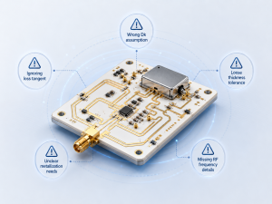
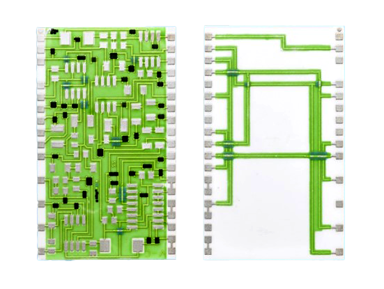
Ceramic circuit board material selection decides how a PCB handles heat, voltage, insulation, dimensional stability, assembly stress and long-term reliability. The practical choice is usually not simply ceramic versus non-ceramic; it is whether alumina, aluminum nitride, FR4, metal core PCB or another substrate can meet the electrical, thermal, mechanical and cost targets of the design.
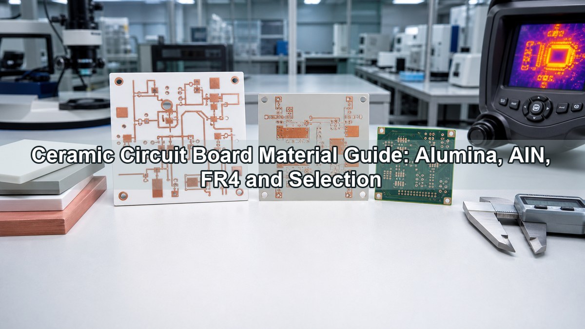
This guide focuses on the material decisions that affect real PCB and PCBA projects: when ceramic is necessary, when FR4 PCB is still the better option, how alumina PCB differs from aluminum nitride PCB, and what information should be prepared before asking a ceramic PCB manufacturer for a quote.
What Is Ceramic Circuit Board Material?
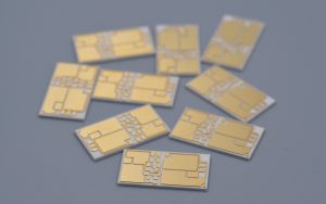
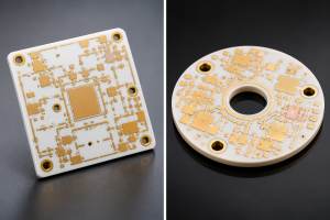
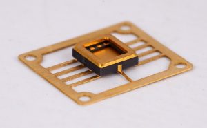
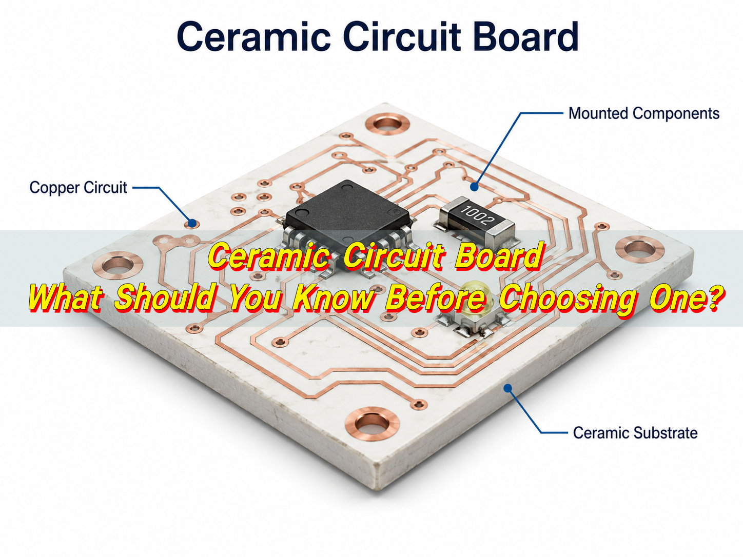
Ceramic circuit board material is an inorganic insulating substrate used as the base for copper circuitry. Common choices include alumina (Al2O3), aluminum nitride (AlN), beryllium oxide (BeO), silicon nitride (Si3N4), LTCC and HTCC materials. In a finished ceramic PCB, the ceramic base supports copper traces while providing electrical insulation and heat transfer.
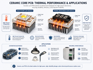
Compared with organic laminates, ceramic substrates are selected for higher thermal conductivity, low moisture absorption, high-temperature stability, dimensional stability and good dielectric strength. These strengths are useful in LED modules, power devices, RF circuits, sensors, laser modules, semiconductor packaging and automotive electronics.
Why Use Ceramic PCB Instead of Standard FR4?
Use ceramic PCB instead of standard FR4 when the board must transfer heat through an electrically insulating substrate or operate in an environment where organic laminate properties are no longer enough. FR4 is economical, easy to process and flexible for multilayer routing, but ceramic provides a stronger platform for heat, voltage, stability and temperature resistance.
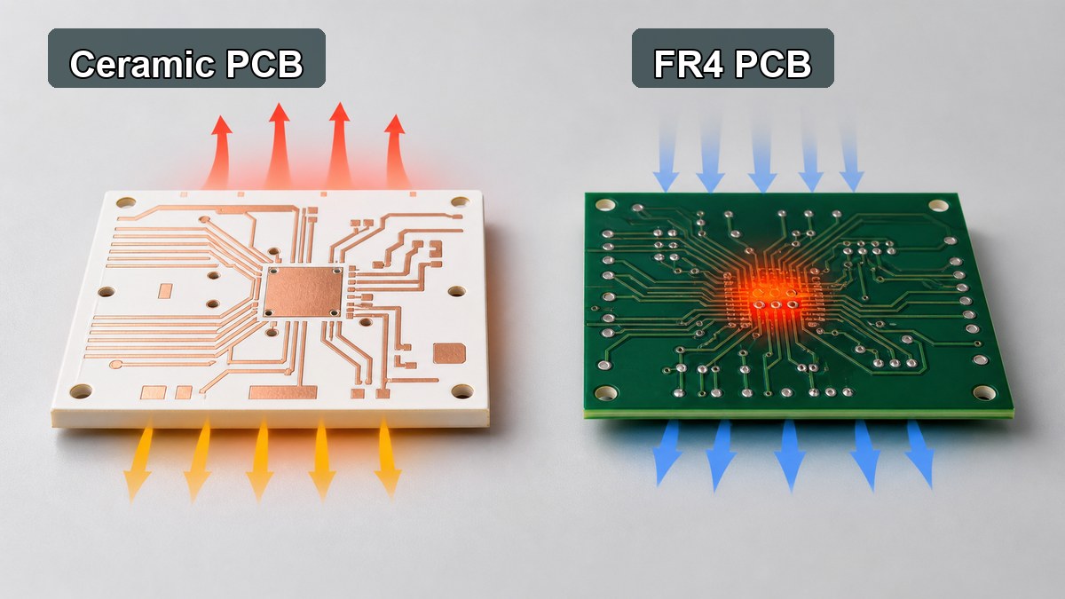
The decision should start from the stress in the design. If the circuit only needs standard digital routing, moderate current and normal operating temperature, FR4 is usually the practical first option. If the design concentrates heat under power devices, requires stable insulation at elevated temperature, or needs a compact high-power structure, ceramic PCB becomes worth reviewing.
| Selection Factor | FR4 PCB | Ceramic PCB |
| Base material | Glass fiber reinforced epoxy laminate | Alumina, AlN, BeO, Si3N4, LTCC or HTCC ceramic |
| Thermal path | Limited through-thickness heat transfer | Better heat transfer through an insulating base |
| Routing flexibility | Excellent for multilayer signal routing | Usually simpler layer structures, depending on process |
| Temperature stability | Suitable for standard electronics and high-Tg options | Better for high-temperature and high-reliability environments |
| Cost position | Lower cost and broad availability | Higher cost, justified by thermal or environmental requirements |
Which Ceramic Circuit Board Materials Are Commonly Used?
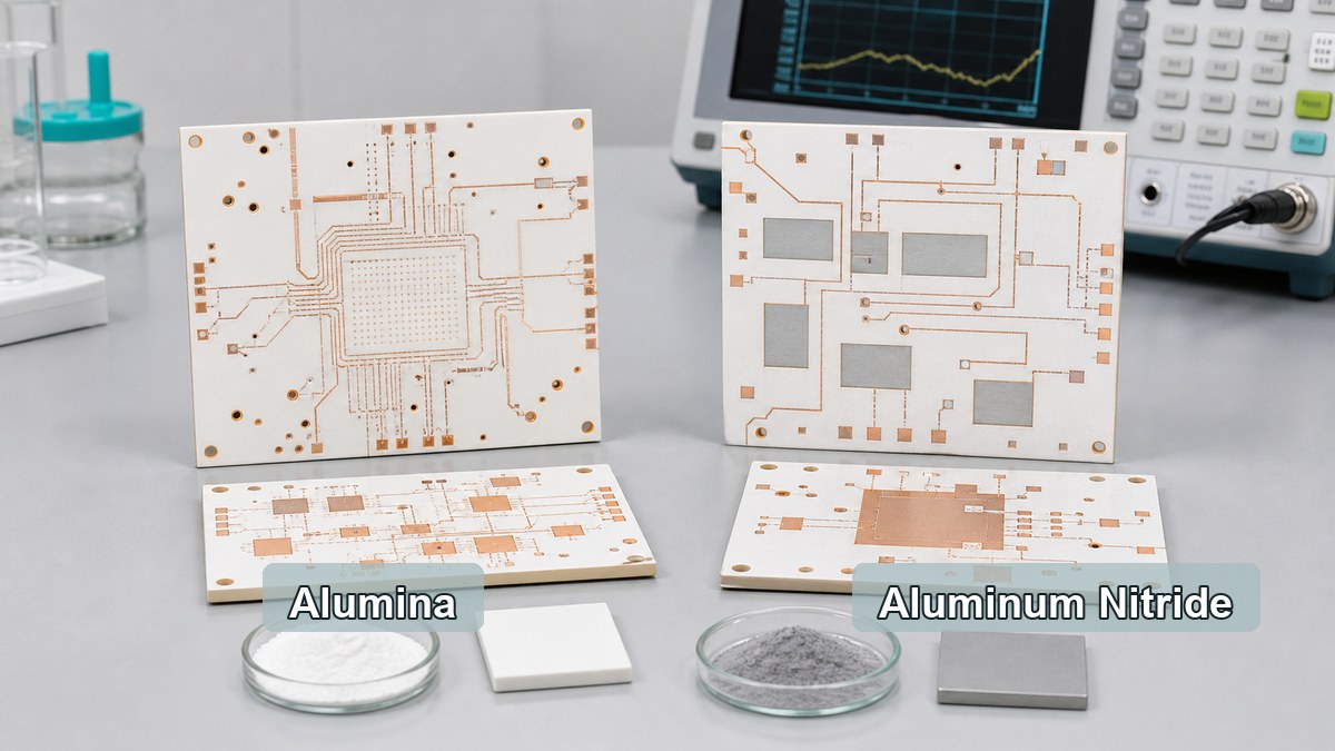
The most common ceramic circuit board materials are alumina and aluminum nitride, with other ceramic systems used when the application has special thermal, RF, packaging or reliability needs. The material name should be connected to the circuit process, copper thickness, surface finish, assembly method and reliability target.
| Material | Practical Strength | Typical Use | Review Point |
| Alumina ceramic substrate | Balanced insulation, stability and cost | LED, sensors, power control, thick film and DPC ceramic circuits | Confirm purity, thickness, copper process and thermal target. |
| Aluminum nitride PCB | Higher thermal conductivity than alumina | High heat flux modules, laser drivers, power electronics and compact LED systems | Confirm handling, cost and metallization compatibility. |
| BeO ceramic PCB | Very high thermal conductivity | Special thermal applications where permitted | Confirm safety, compliance and supplier capability before selection. |
| LTCC / HTCC | Multilayer ceramic packaging and high-reliability structures | RF modules, sensors, hermetic or compact electronic packages | Confirm design rules, firing shrinkage, conductor system and lead time. |
When Is Alumina PCB the Practical Choice?
Alumina PCB is often the practical choice when the design needs ceramic insulation, dimensional stability and better thermal behavior than FR4, but does not require the higher thermal performance or cost of AlN. It is commonly used for ceramic circuits where cost control, mature processing and stable electrical insulation matter together.
For many projects, 96% alumina provides a balanced ceramic substrate for DPC, thick film and other ceramic PCB routes. Higher-purity alumina can be considered when tighter dielectric performance, surface quality or material consistency is important. The decision should be made with substrate thickness, copper thickness, line width, dielectric test requirement and assembly conditions in the same review.
When Should Aluminum Nitride PCB Be Selected?
Aluminum nitride PCB should be selected when the limiting factor is heat spreading through the insulating substrate. AlN has much stronger thermal conductivity than alumina, so it is useful in compact power modules, high-power LED systems, laser modules, RF power circuits and applications where the heat source is small and concentrated.
AlN is not automatically the best material for every ceramic PCB. It usually costs more than alumina and requires careful handling and process control. It should be reviewed when thermal simulation, junction temperature, power density or module size shows that alumina cannot provide enough thermal margin.
How Do Ceramic Circuit Boards Compare With Metal Core PCB?
Ceramic circuit boards and metal core PCBs solve heat problems in different ways. A metal core PCB uses a metal base, usually aluminum or copper, with an insulating dielectric layer between the copper circuit and the metal. A ceramic PCB uses the ceramic itself as the electrically insulating and heat-conducting base.
Metal core PCB is often effective for LED lighting, power supplies and thermal spreading where the dielectric layer can meet the voltage and thermal requirements. Ceramic PCB becomes more relevant when the insulation layer must also be highly thermally conductive, dimensionally stable, low moisture absorption or suitable for elevated-temperature operation.
Which Manufacturing Processes Affect Ceramic PCB Material Selection?
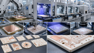
The manufacturing process affects ceramic PCB material selection because the same substrate can behave differently in thick film, thin film, DPC, DCB or other ceramic circuit routes. The process determines achievable line width, copper thickness, adhesion, surface finish, layer count, vias, cost and lead time.
- Thick film ceramic PCB: suitable for printed conductor and resistor systems, commonly used on alumina.
- Thin film ceramic PCB: useful for fine features, tight tolerances and high-frequency or precision circuits.
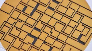
- DPC ceramic PCB: supports plated copper features and is often used for LED, sensor and compact power applications.
- DCB / DBC ceramic PCB: supports bonded copper on ceramic for higher-current power structures.
- LTCC / HTCC: used when multilayer ceramic integration, compact packaging or high-temperature firing processes are needed.
EBest Circuit (Best Technology) supports ceramic PCB routes including thick film ceramic PCB, thin film ceramic PCB, DCB ceramic PCB, alumina ceramic PCB and AlN ceramic PCB, subject to material, dimensions, copper design and engineering review.
What Applications Need Ceramic Circuit Board Material?
Ceramic circuit board material is most useful when the application combines heat, electrical insulation, compact size or environmental stress. It is not limited to one industry, but it is most common where ordinary organic laminates would create thermal, dielectric or reliability limits.
- High-power LED modules and optical devices
- Laser diode and laser driver circuits
- Power semiconductor modules and gate driver substrates
- RF and microwave ceramic circuits
- Automotive sensors and power electronics
- Medical electronics and high-reliability instruments
- Industrial controls exposed to heat or electrical stress
What Should Be Checked Before Requesting a Ceramic PCB Quote?
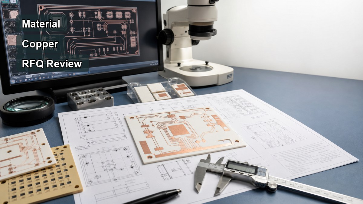
A ceramic PCB quote should include more than the material name. The RFQ should define the complete substrate and circuit structure so the manufacturer can review feasibility, cost and reliability before production.
- Ceramic material: alumina, AlN, BeO, LTCC, HTCC or open for recommendation
- Substrate thickness, copper thickness and finished board size
- Line width, line spacing, hole size, vias and edge clearance
- Process route: thick film, thin film, DPC, DCB or another ceramic process
- Surface finish and soldering or wire bonding requirement
- Operating temperature, voltage, current and thermal load
- Assembly method, component type, solder profile and inspection needs
- Prototype quantity, annual volume and target lead time
For a first build, a PCB prototype is usually the most practical way to validate material choice, circuit layout, assembly behavior and thermal assumptions before committing to volume production.
How Should You Choose a Ceramic PCB Manufacturer?
A ceramic PCB manufacturer should be evaluated by material capability, process match, engineering communication, inspection methods and willingness to review trade-offs before quotation. A supplier that only accepts a material name without checking drawings may miss important limits in copper geometry, substrate thickness, thermal stress or assembly compatibility.
EBest Circuit (Best Technology) can review ceramic PCB drawings together with FR4 PCB, MCPCB and PCB assembly requirements when the project includes mixed technologies. This is useful when the final product uses a ceramic circuit for the high-heat section and conventional PCBA for control, sensing or communication circuits.
FAQ About Ceramic Circuit Board Material?
1. Is ceramic PCB always better than FR4?
No. Ceramic PCB is better when the project needs ceramic-specific thermal, dielectric or temperature performance. FR4 is usually better for cost-sensitive multilayer routing, standard digital circuits and general electronics.
2. Is alumina PCB the same as aluminum nitride PCB?
No. Alumina PCB and aluminum nitride PCB are different ceramic substrate options. Alumina is often more cost-effective, while aluminum nitride is selected when higher thermal conductivity is needed.
3. Can ceramic circuit boards be assembled like standard PCBs?
Some assembly steps are similar, but ceramic boards need attention to solder profile, component stress, handling, surface finish and thermal expansion behavior. Assembly review should happen before prototype production.
4. What files are needed for a ceramic PCB quote?
Gerber files, drill files, board drawing, stack details, material requirement, copper thickness, surface finish, quantity, assembly notes and thermal or electrical requirements are normally needed for a useful quotation.
5. Should circuit board cement or circuit board clay be used as article keywords?
No. Those terms usually do not match ceramic PCB material selection intent. They should not guide the article structure unless a specific repair, adhesive or educational material topic is being written separately.
Conclusion
Ceramic circuit board material should be selected only after the thermal path, voltage requirement, substrate thickness, copper design, assembly method and cost target are clear. Alumina PCB is often the balanced ceramic option, aluminum nitride PCB is stronger for high heat flux, and FR4 remains the practical choice for many standard circuits.
If you are comparing ceramic PCB, FR4 PCB, metal core PCB or PCBA options, EBest Circuit (Best Technology) can review your drawings, material requirements and quotation details. Send your files or questions to sales@bestpcbs.com or contact EBest Circuit.