PCB manufacturing PCB manufacturing
Home > Blog

Alumina PCB

Alumina Heat Conductivity: Values, Temperature Effects and PCB Use
Friday, July 17th, 2026

Alumina heat conductivity describes how well aluminum oxide ceramic transfers heat through its structure. For PCB and electronic packaging work, dense alumina substrates are commonly discussed around 20-30 W/m·K at room temperature, depending on purity, density, microstructure and supplier data. That is far above standard FR4, but far below aluminum nitride, so the right choice depends on heat load, insulation, cost, copper design and the complete thermal path.
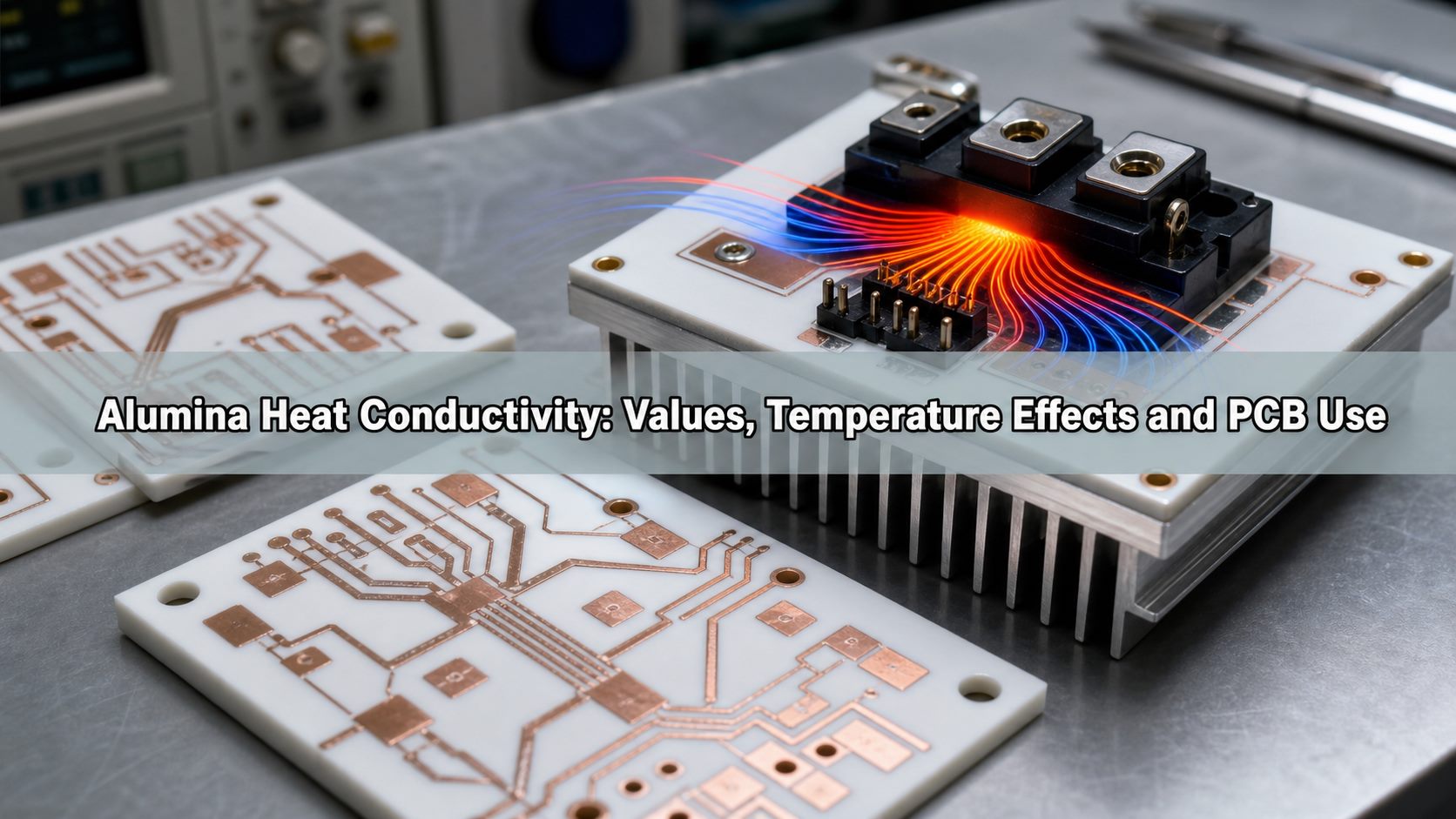
Alumina heat conductivity values temperature effects and PCB use

Alumina is attractive because it combines useful thermal transfer with strong electrical insulation, mechanical hardness, chemical stability and mature ceramic PCB processing. In a real board, however, the material value alone does not determine device temperature. Ceramic thickness, copper coverage, solder or sinter layer, interface material, heat sink flatness and airflow all change the final result.

What Is Alumina Heat Conductivity?

Alumina heat conductivity is the rate at which alumina, also known as aluminum oxide or Al2O3, conducts heat. In engineering data sheets it is usually expressed as thermal conductivity in W/m·K. A higher value means heat can move through the material more easily under the same temperature gradient.

For PCB buyers, the term is often used when comparing ceramic PCB substrates with FR4, metal core PCB and aluminum nitride ceramic. Alumina is not a metal heat spreader, but it conducts heat much better than ordinary organic PCB laminates while maintaining electrical isolation. This makes it useful where a circuit needs both insulation and a shorter heat path.

What Is the Typical Thermal Conductivity of Alumina?

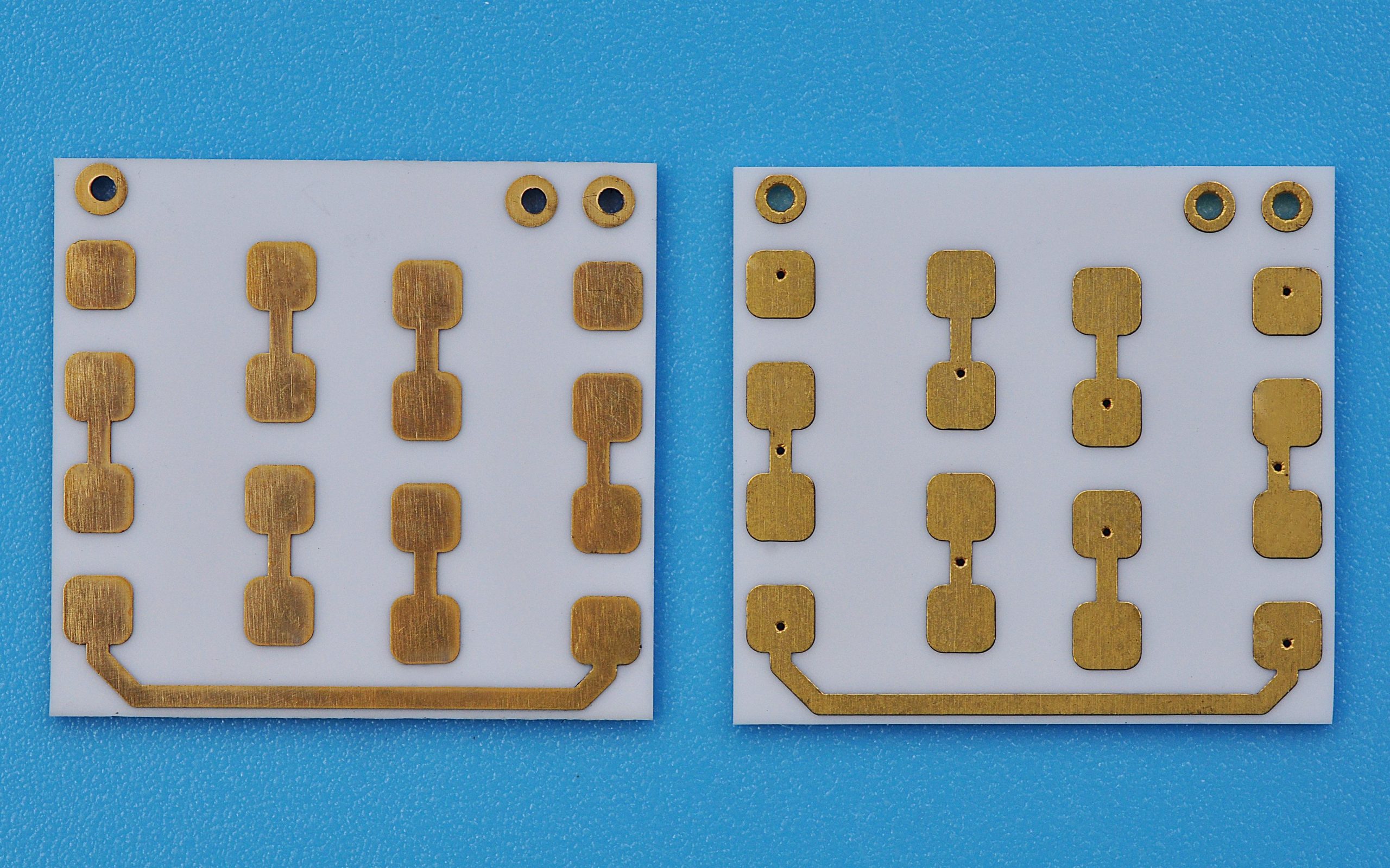
Typical dense alumina ceramic used for electronics substrates is often specified around 20-30 W/m·K, while very dense or high-purity alumina grades may be listed higher by some material suppliers. The exact value should always be taken from the ceramic supplier’s data sheet because purity, porosity, grain structure and processing route can change the result.
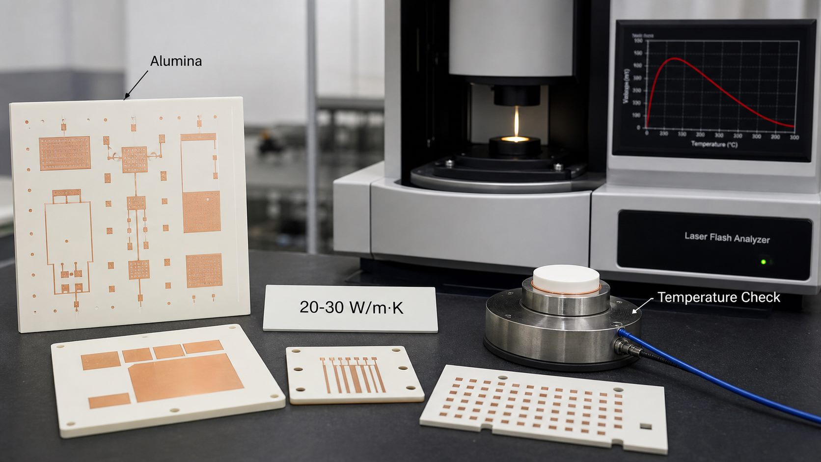
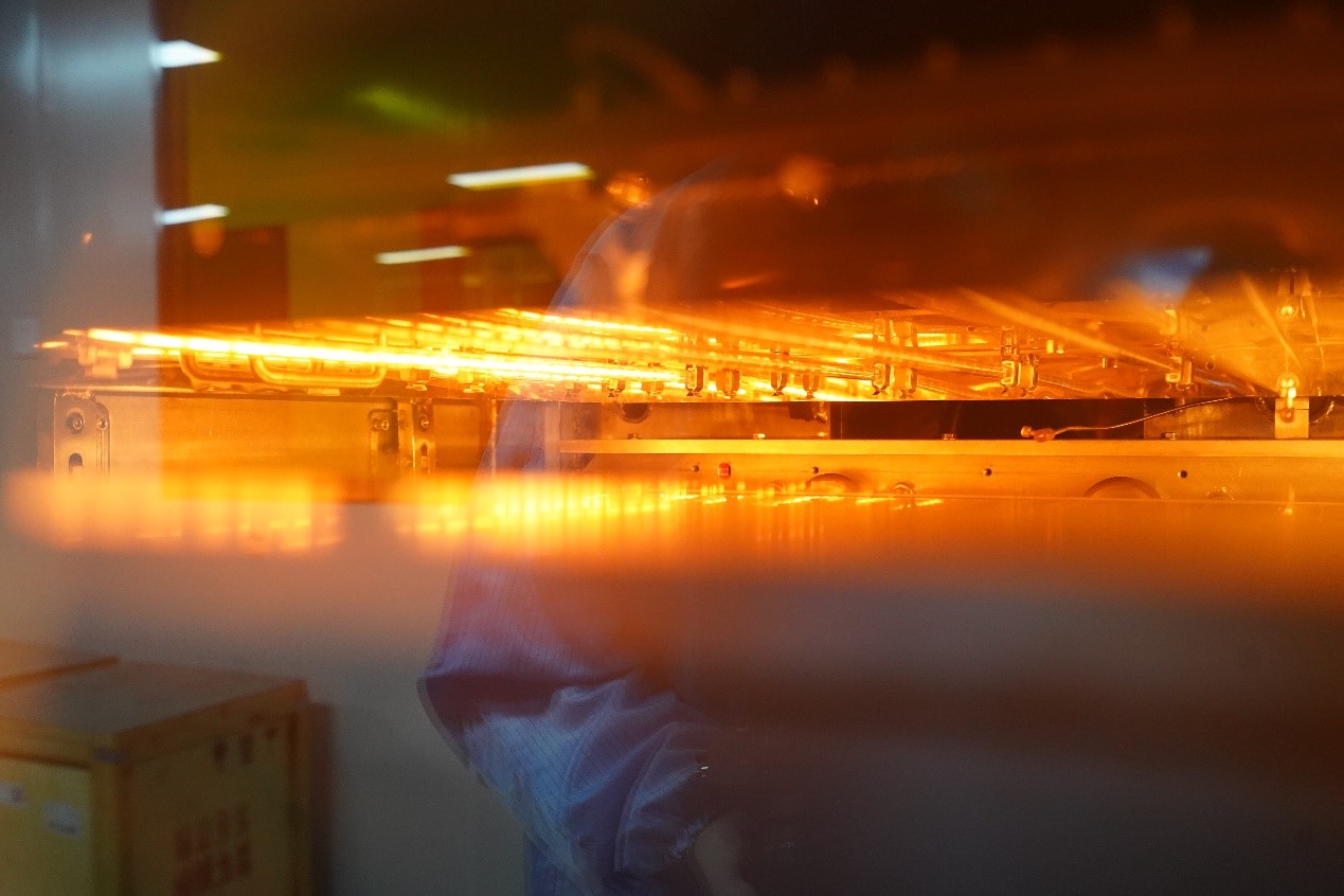
Alumina ceramic PCB thermal conductivity testing and temperature check

For practical ceramic PCB selection, it is safer to treat alumina as a balanced thermal-insulating material rather than a maximum-conductivity material. If a design only needs moderate heat spreading, alumina can be a cost-effective choice. If the component has very high heat flux, AlN or another high-thermal-conductivity substrate may need review.

Is Alumina Conductive or Electrically Insulating?

Alumina is thermally conductive compared with FR4, but it is electrically insulating under normal electronics operating conditions. This distinction matters because many searches for “alumina conductivity” mix thermal conductivity and electrical conductivity into one phrase.

In PCB use, the value of alumina is that heat can pass through the ceramic while voltage isolation is maintained between copper features, components and the heat sink. This is why alumina ceramic substrates are used in LED modules, sensor circuits, power resistors, hybrid circuits, automotive electronics and other designs where heat and insulation must be handled together.

How Does Alumina Thermal Conductivity Change with Temperature?

Alumina thermal conductivity generally decreases as temperature rises because phonon scattering increases inside the ceramic. Published research and material databases show that temperature-dependent values can vary significantly by sample type, density and measurement method.

For PCB design, this means a room-temperature conductivity value should not be used blindly for high-temperature operation. If the board will operate near a hot device, inside an enclosed module or under repeated thermal cycling, request temperature-dependent material data and validate the full stack under the expected operating range.

How Do Alumina, FR4, MCPCB and AlN Compare?

The useful comparison is not “which material has the highest heat conductivity” in isolation. The better question is which material gives enough heat transfer, insulation, reliability and manufacturability for the assembly.
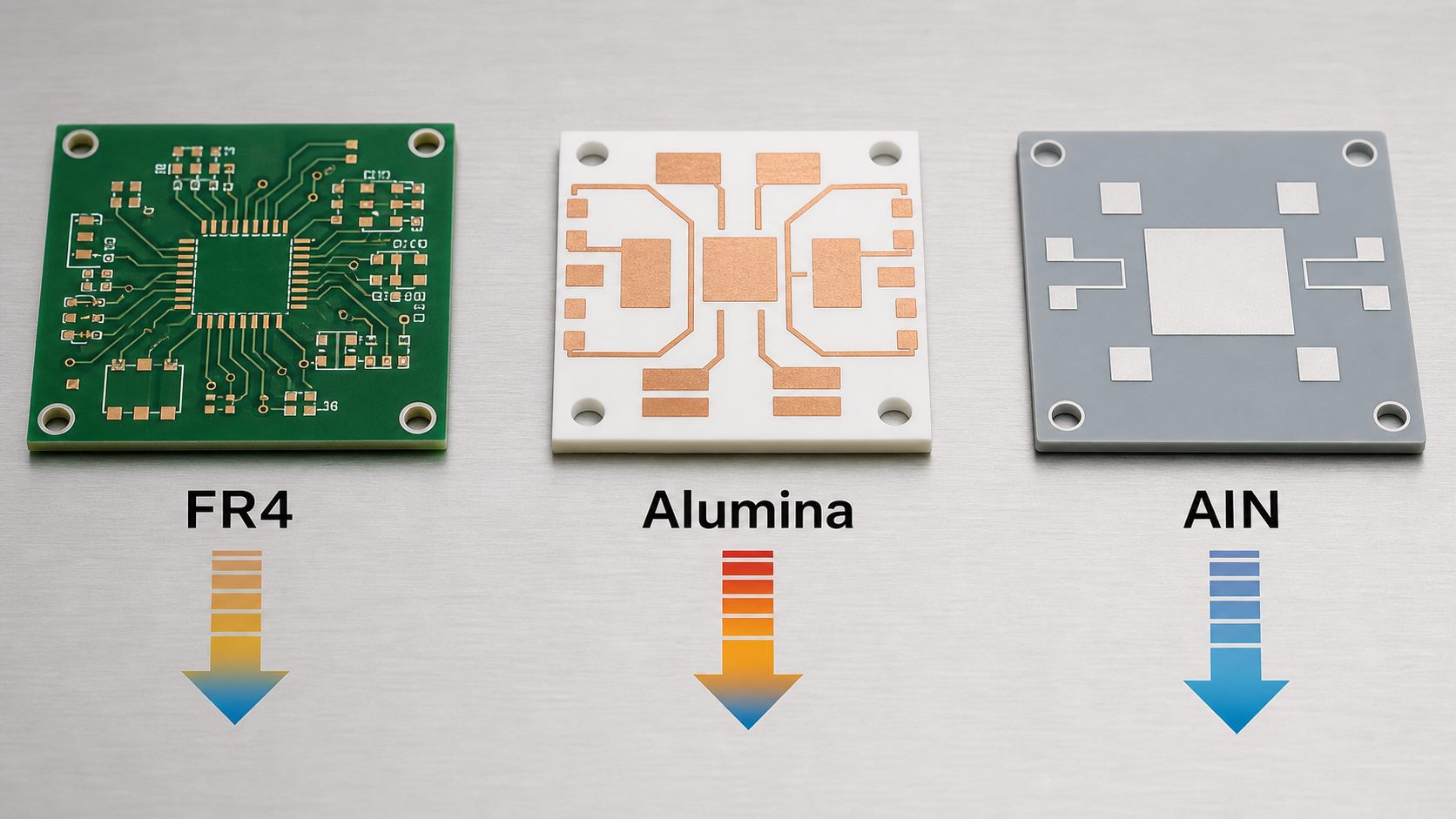
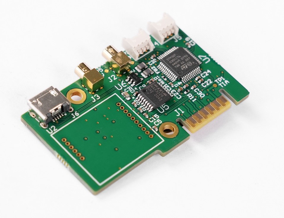
FR4 alumina and AlN substrate heat conductivity comparison
Material Typical Thermal Role Electrical Behavior Best Fit
FR4 Low thermal conductivity Insulating laminate Standard control circuits, signal boards and low-heat designs
MCPCB Uses a metal base and dielectric layer for heat spreading Dielectric layer provides isolation LED lighting, power boards and cost-sensitive thermal designs
Alumina ceramic PCB Moderate-to-good ceramic thermal conductivity Electrical insulator Insulated ceramic circuits needing stable cost, hardness and heat transfer
AlN ceramic PCB High ceramic thermal conductivity Electrical insulator High heat flux, compact power modules, laser drivers and demanding thermal paths

If the design is mainly limited by FR4’s poor heat transfer, alumina may be enough. If the design is limited by junction temperature in a compact high-power package, compare alumina with high thermal conductivity ceramic PCB options such as AlN.

Which Alumina Properties Matter Besides Heat Conductivity?

Alumina properties should be reviewed as a package, not as a single thermal number. Heat conductivity is important, but density, specific heat capacity, hardness, dielectric strength, CTE, surface roughness and flatness can all affect PCB performance and assembly reliability.

  • Density: Higher density usually means fewer pores and more stable mechanical and thermal behavior.
  • Specific heat capacity: This affects how much heat the ceramic can absorb before its temperature rises.
  • Hardness: Alumina is hard and wear-resistant, but machining, laser cutting and drilling require ceramic-capable processes.
  • CTE: Thermal expansion affects copper stress, solder fatigue and compatibility with components.
  • Surface quality: Thin film, thick film, DPC and DBC processes may require different surface conditions.

For sourcing, ask whether the quoted value is for 96% alumina, 99.6% alumina or another grade. A higher-purity material may support better surface quality or stability, but it may not automatically solve every thermal or cost problem.

When Is Alumina Ceramic PCB a Good Choice?

Alumina ceramic PCB is a good choice when the design needs better heat transfer than FR4, strong electrical insulation, good mechanical strength and a more cost-accessible ceramic option than AlN. It is often practical for medium-power modules, LED substrates, sensor electronics, thick-film circuits, precision resistive circuits and industrial control boards.

Alumina also fits projects where production availability and process maturity matter. EBest Circuit (Best Technology) supports ceramic PCB projects including alumina and AlN options, and engineering review can help determine whether ceramic substrate selection, copper thickness and surface finish match the operating conditions.

When Is Alumina Not Enough for Thermal Management?

Alumina may not be enough when the heat source is very small, the power density is high, the board has limited copper area, or the assembly has a weak interface to the heat sink. In those cases, upgrading the substrate alone may not fix the thermal bottleneck unless the full stack is redesigned.

AlN should be considered when thermal conductivity is the controlling requirement and the project can justify the higher material and processing cost. BeO has high thermal conductivity, but its toxicity and handling restrictions make it unsuitable for many commercial PCB programs. For cost-sensitive ceramic designs, review whether a cost-effective Al2O3 ceramic PCB approach can meet the thermal target before moving to a higher-cost material.

How Do Thickness, Copper Area and Interfaces Change Heat Transfer?

Thermal conductivity is a material property, while heat transfer in a PCB assembly depends on geometry and interfaces. A thinner alumina substrate can reduce through-thickness thermal resistance, but it may reduce mechanical margin. Larger copper areas can spread heat, but copper imbalance may increase stress and warpage.

Alumina ceramic PCB thermal path from component through copper and ceramic to heat sink

The interface between the ceramic board and heat sink is often as important as the ceramic itself. Gaps, poor flatness, insufficient mounting pressure or unsuitable thermal interface material can cancel part of the benefit gained from a better substrate. A useful thermal review should include component footprint, copper layout, ceramic thickness, surface finish, mounting method and cooling structure.

What Should Buyers Provide for an Alumina Ceramic PCB RFQ?

An alumina ceramic PCB RFQ should provide enough technical data to judge thermal path, manufacturability and reliability. A request that only says “need alumina PCB” is usually too vague for accurate quotation or process advice.
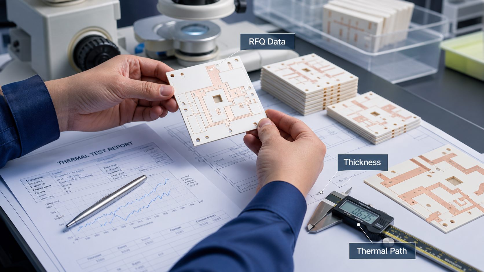
Alumina ceramic PCB RFQ review for thermal design and production checks
  • Target alumina grade, such as 96% or 99.6%, or permission for supplier recommendation.
  • Ceramic thickness, outline size, holes, slots and tolerance requirements.
  • Copper thickness, minimum line and spacing, copper balance and surface finish.
  • Expected heat source size, power dissipation, operating temperature and cooling method.
  • Electrical insulation requirement, voltage clearance and dielectric test expectations.
  • Manufacturing route preference: thick film, thin film, DPC, DBC or open for review.
  • Prototype quantity, annual volume, inspection requirements and assembly method.

For projects that also require component mounting, BOM review or testing, EBest Circuit can review PCB fabrication and PCBA needs together. Send drawings, stack-up notes, thermal assumptions and quantity targets to contact EBest Circuit or email sales@bestpcbs.com.

FAQ About Alumina Heat Conductivity?

1. What is heat conductivity?
Heat conductivity, usually called thermal conductivity in engineering, is a material’s ability to conduct heat. It is measured in W/m·K and helps compare how quickly heat can pass through different materials.

2. Is alumina a good conductor of heat?
Alumina is a good heat conductor compared with FR4 and many insulating polymers, but it is not as conductive as metals or aluminum nitride ceramic. It is best viewed as an electrically insulating ceramic with useful thermal performance.

3. Is alumina electrically conductive?
No. Alumina is normally used as an electrical insulator in PCB and electronic packaging applications. Its value is that it can transfer heat while helping maintain electrical isolation.

4. What material has the highest heat conductivity for ceramic PCBs?
Among common ceramic PCB materials, BeO has very high thermal conductivity but serious handling restrictions. AlN is a more common high-conductivity ceramic choice for electronics, while alumina is chosen for balanced cost, availability and insulation.

5. Does alumina thermal conductivity change with temperature?
Yes. Alumina thermal conductivity generally decreases as temperature rises, so high-temperature designs should use temperature-dependent data rather than relying only on a room-temperature number.

6. Is alumina hazardous?
Finished alumina ceramic substrates are generally stable in normal use, but ceramic dust from machining or grinding should be controlled with proper industrial safety practices. Buyers should request material and process compliance information when needed.

Conclusion

Alumina heat conductivity is useful because it gives PCB designers a thermally capable ceramic substrate while preserving electrical insulation and mechanical stability. The important decision is not only the W/m·K value. Ceramic grade, thickness, copper layout, interface material, heat sink design, temperature range and production process all affect the final thermal result.

If you are evaluating alumina ceramic PCB, AlN ceramic PCB or a mixed PCB/PCBA build, EBest Circuit (Best Technology) can review your drawings, thermal assumptions, process route and quotation files. For engineering review or quotation, contact sales@bestpcbs.com.
You may also like

Ceramic Circuit Board Material Guide: Alumina, AlN, FR4 and Selection
Friday, July 17th, 2026

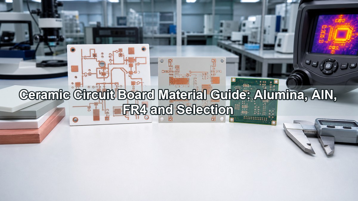
Ceramic circuit board material selection decides how a PCB handles heat, voltage, insulation, dimensional stability, assembly stress and long-term reliability. The practical choice is usually not simply ceramic versus non-ceramic; it is whether alumina, aluminum nitride, FR4, metal core PCB or another substrate can meet the electrical, thermal, mechanical and cost targets of the design.

Ceramic circuit board material guide showing alumina and aluminum nitride PCB substrates

This guide focuses on the material decisions that affect real PCB and PCBA projects: when ceramic is necessary, when FR4 PCB is still the better option, how alumina PCB differs from aluminum nitride PCB, and what information should be prepared before asking a ceramic PCB manufacturer for a quote.

What Is Ceramic Circuit Board Material?

Ceramic circuit board material is an inorganic insulating substrate used as the base for copper circuitry. Common choices include alumina (Al2O3), aluminum nitride (AlN), beryllium oxide (BeO), silicon nitride (Si3N4), LTCC and HTCC materials. In a finished ceramic PCB, the ceramic base supports copper traces while providing electrical insulation and heat transfer.

Compared with organic laminates, ceramic substrates are selected for higher thermal conductivity, low moisture absorption, high-temperature stability, dimensional stability and good dielectric strength. These strengths are useful in LED modules, power devices, RF circuits, sensors, laser modules, semiconductor packaging and automotive electronics.

Why Use Ceramic PCB Instead of Standard FR4?

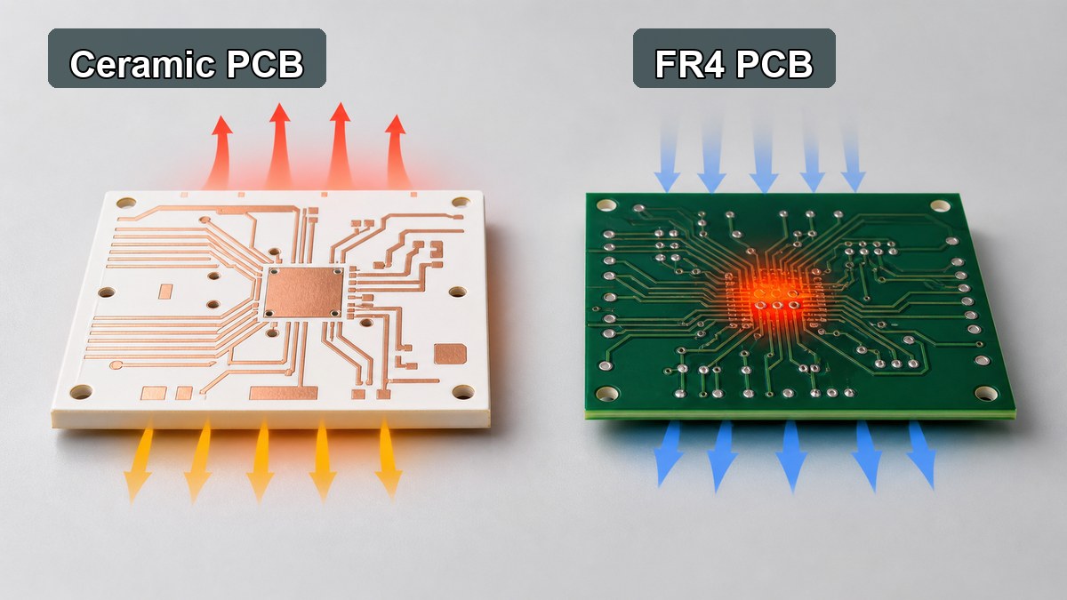
Use ceramic PCB instead of standard FR4 when the board must transfer heat through an electrically insulating substrate or operate in an environment where organic laminate properties are no longer enough. FR4 is economical, easy to process and flexible for multilayer routing, but ceramic provides a stronger platform for heat, voltage, stability and temperature resistance.

Ceramic PCB vs FR4 material comparison for heat and insulation

The decision should start from the stress in the design. If the circuit only needs standard digital routing, moderate current and normal operating temperature, FR4 is usually the practical first option. If the design concentrates heat under power devices, requires stable insulation at elevated temperature, or needs a compact high-power structure, ceramic PCB becomes worth reviewing.

Selection Factor FR4 PCB Ceramic PCB
Base material Glass fiber reinforced epoxy laminate Alumina, AlN, BeO, Si3N4, LTCC or HTCC ceramic
Thermal path Limited through-thickness heat transfer Better heat transfer through an insulating base
Routing flexibility Excellent for multilayer signal routing Usually simpler layer structures, depending on process
Temperature stability Suitable for standard electronics and high-Tg options Better for high-temperature and high-reliability environments
Cost position Lower cost and broad availability Higher cost, justified by thermal or environmental requirements

Which Ceramic Circuit Board Materials Are Commonly Used?

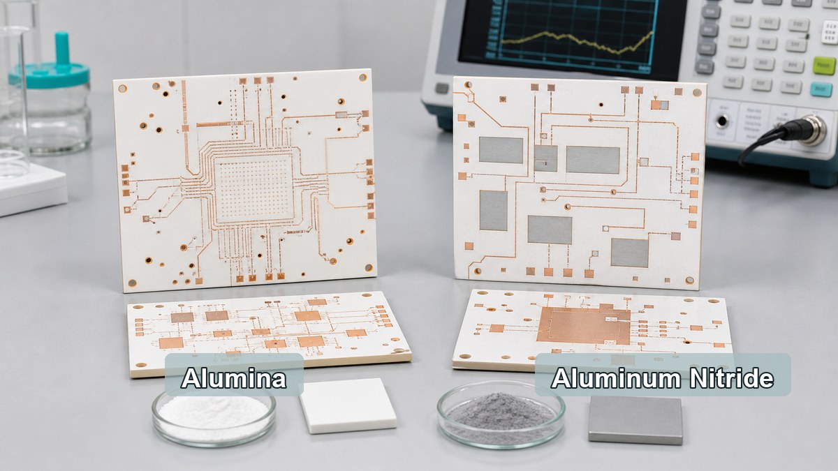
The most common ceramic circuit board materials are alumina and aluminum nitride, with other ceramic systems used when the application has special thermal, RF, packaging or reliability needs. The material name should be connected to the circuit process, copper thickness, surface finish, assembly method and reliability target.

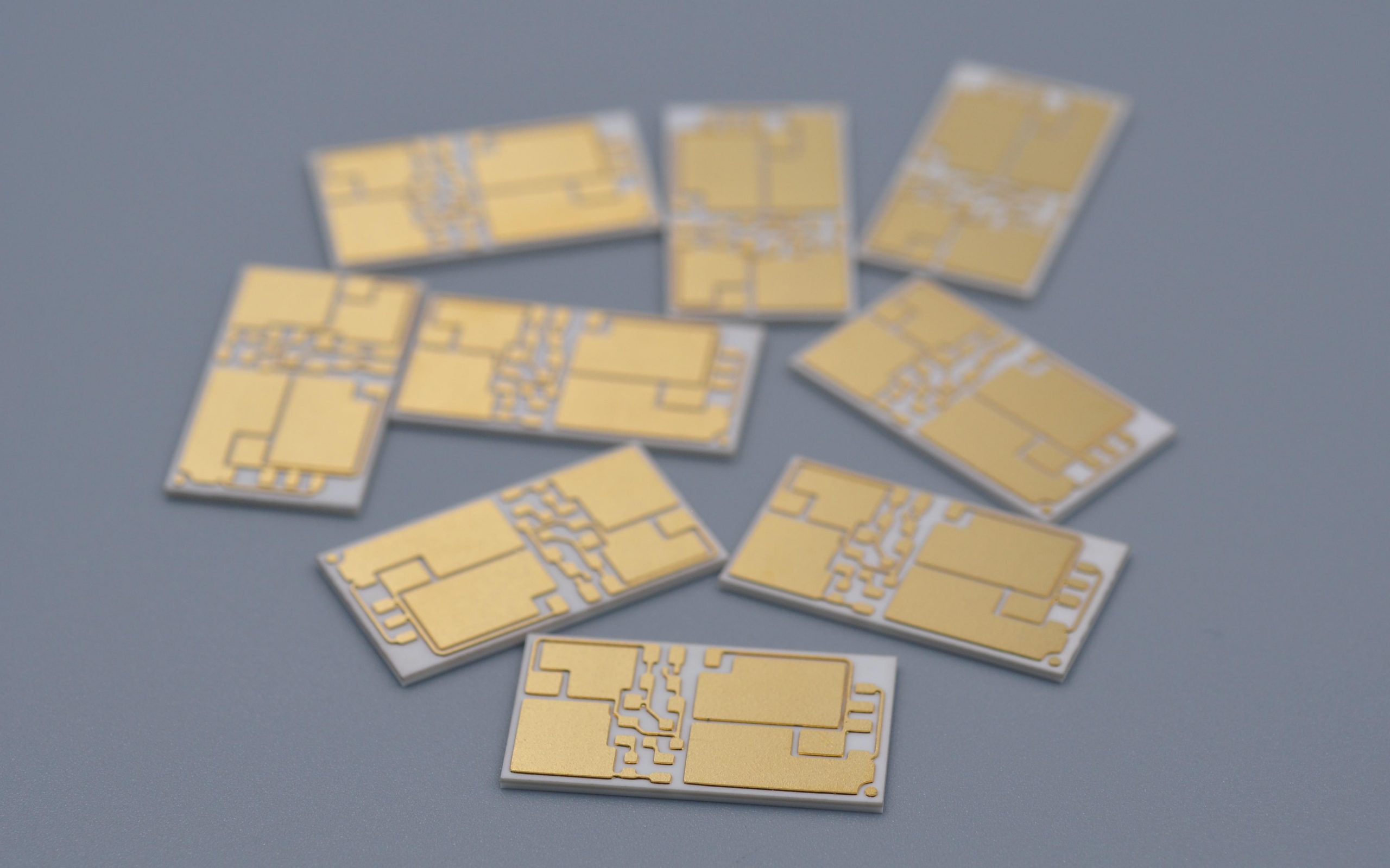
Alumina and aluminum nitride ceramic substrate selection for PCB projects
Material Practical Strength Typical Use Review Point
Alumina ceramic substrate Balanced insulation, stability and cost LED, sensors, power control, thick film and DPC ceramic circuits Confirm purity, thickness, copper process and thermal target.
Aluminum nitride PCB Higher thermal conductivity than alumina High heat flux modules, laser drivers, power electronics and compact LED systems Confirm handling, cost and metallization compatibility.
BeO ceramic PCB Very high thermal conductivity Special thermal applications where permitted Confirm safety, compliance and supplier capability before selection.
LTCC / HTCC Multilayer ceramic packaging and high-reliability structures RF modules, sensors, hermetic or compact electronic packages Confirm design rules, firing shrinkage, conductor system and lead time.

When Is Alumina PCB the Practical Choice?

Alumina PCB is often the practical choice when the design needs ceramic insulation, dimensional stability and better thermal behavior than FR4, but does not require the higher thermal performance or cost of AlN. It is commonly used for ceramic circuits where cost control, mature processing and stable electrical insulation matter together.

For many projects, 96% alumina provides a balanced ceramic substrate for DPC, thick film and other ceramic PCB routes. Higher-purity alumina can be considered when tighter dielectric performance, surface quality or material consistency is important. The decision should be made with substrate thickness, copper thickness, line width, dielectric test requirement and assembly conditions in the same review.

When Should Aluminum Nitride PCB Be Selected?

Aluminum nitride PCB should be selected when the limiting factor is heat spreading through the insulating substrate. AlN has much stronger thermal conductivity than alumina, so it is useful in compact power modules, high-power LED systems, laser modules, RF power circuits and applications where the heat source is small and concentrated.

AlN is not automatically the best material for every ceramic PCB. It usually costs more than alumina and requires careful handling and process control. It should be reviewed when thermal simulation, junction temperature, power density or module size shows that alumina cannot provide enough thermal margin.

How Do Ceramic Circuit Boards Compare With Metal Core PCB?

Ceramic circuit boards and metal core PCBs solve heat problems in different ways. A metal core PCB uses a metal base, usually aluminum or copper, with an insulating dielectric layer between the copper circuit and the metal. A ceramic PCB uses the ceramic itself as the electrically insulating and heat-conducting base.

Metal core PCB is often effective for LED lighting, power supplies and thermal spreading where the dielectric layer can meet the voltage and thermal requirements. Ceramic PCB becomes more relevant when the insulation layer must also be highly thermally conductive, dimensionally stable, low moisture absorption or suitable for elevated-temperature operation.

Which Manufacturing Processes Affect Ceramic PCB Material Selection?

The manufacturing process affects ceramic PCB material selection because the same substrate can behave differently in thick film, thin film, DPC, DCB or other ceramic circuit routes. The process determines achievable line width, copper thickness, adhesion, surface finish, layer count, vias, cost and lead time.

  • Thick film ceramic PCB: suitable for printed conductor and resistor systems, commonly used on alumina.
  • Thin film ceramic PCB: useful for fine features, tight tolerances and high-frequency or precision circuits.
  • DPC ceramic PCB: supports plated copper features and is often used for LED, sensor and compact power applications.
  • DCB / DBC ceramic PCB: supports bonded copper on ceramic for higher-current power structures.
  • LTCC / HTCC: used when multilayer ceramic integration, compact packaging or high-temperature firing processes are needed.

EBest Circuit (Best Technology) supports ceramic PCB routes including thick film ceramic PCB, thin film ceramic PCB, DCB ceramic PCB, alumina ceramic PCB and AlN ceramic PCB, subject to material, dimensions, copper design and engineering review.

What Applications Need Ceramic Circuit Board Material?

Ceramic circuit board material is most useful when the application combines heat, electrical insulation, compact size or environmental stress. It is not limited to one industry, but it is most common where ordinary organic laminates would create thermal, dielectric or reliability limits.

  • High-power LED modules and optical devices
  • Laser diode and laser driver circuits
  • Power semiconductor modules and gate driver substrates
  • RF and microwave ceramic circuits
  • Automotive sensors and power electronics
  • Medical electronics and high-reliability instruments
  • Industrial controls exposed to heat or electrical stress

What Should Be Checked Before Requesting a Ceramic PCB Quote?

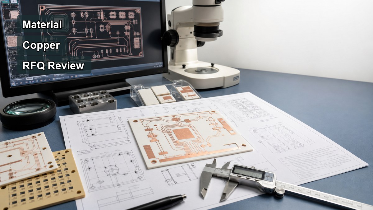
A ceramic PCB quote should include more than the material name. The RFQ should define the complete substrate and circuit structure so the manufacturer can review feasibility, cost and reliability before production.

Ceramic PCB manufacturer RFQ checklist for material and process review
  • Ceramic material: alumina, AlN, BeO, LTCC, HTCC or open for recommendation
  • Substrate thickness, copper thickness and finished board size
  • Line width, line spacing, hole size, vias and edge clearance
  • Process route: thick film, thin film, DPC, DCB or another ceramic process
  • Surface finish and soldering or wire bonding requirement
  • Operating temperature, voltage, current and thermal load
  • Assembly method, component type, solder profile and inspection needs
  • Prototype quantity, annual volume and target lead time

For a first build, a PCB prototype is usually the most practical way to validate material choice, circuit layout, assembly behavior and thermal assumptions before committing to volume production.

How Should You Choose a Ceramic PCB Manufacturer?

A ceramic PCB manufacturer should be evaluated by material capability, process match, engineering communication, inspection methods and willingness to review trade-offs before quotation. A supplier that only accepts a material name without checking drawings may miss important limits in copper geometry, substrate thickness, thermal stress or assembly compatibility.

EBest Circuit (Best Technology) can review ceramic PCB drawings together with FR4 PCB, MCPCB and PCB assembly requirements when the project includes mixed technologies. This is useful when the final product uses a ceramic circuit for the high-heat section and conventional PCBA for control, sensing or communication circuits.

FAQ About Ceramic Circuit Board Material?

1. Is ceramic PCB always better than FR4?
No. Ceramic PCB is better when the project needs ceramic-specific thermal, dielectric or temperature performance. FR4 is usually better for cost-sensitive multilayer routing, standard digital circuits and general electronics.

2. Is alumina PCB the same as aluminum nitride PCB?
No. Alumina PCB and aluminum nitride PCB are different ceramic substrate options. Alumina is often more cost-effective, while aluminum nitride is selected when higher thermal conductivity is needed.

3. Can ceramic circuit boards be assembled like standard PCBs?
Some assembly steps are similar, but ceramic boards need attention to solder profile, component stress, handling, surface finish and thermal expansion behavior. Assembly review should happen before prototype production.

4. What files are needed for a ceramic PCB quote?
Gerber files, drill files, board drawing, stack details, material requirement, copper thickness, surface finish, quantity, assembly notes and thermal or electrical requirements are normally needed for a useful quotation.

5. Should circuit board cement or circuit board clay be used as article keywords?
No. Those terms usually do not match ceramic PCB material selection intent. They should not guide the article structure unless a specific repair, adhesive or educational material topic is being written separately.

Conclusion

Ceramic circuit board material should be selected only after the thermal path, voltage requirement, substrate thickness, copper design, assembly method and cost target are clear. Alumina PCB is often the balanced ceramic option, aluminum nitride PCB is stronger for high heat flux, and FR4 remains the practical choice for many standard circuits.

If you are comparing ceramic PCB, FR4 PCB, metal core PCB or PCBA options, EBest Circuit (Best Technology) can review your drawings, material requirements and quotation details. Send your files or questions to sales@bestpcbs.com or contact EBest Circuit.

You may also like

Ceramic PCB for RF: Substrate Materials, Design Benefits, and Manufacturing Guide
Friday, July 10th, 2026

What Is a Ceramic PCB for RF?

A ceramic PCB for RF is a circuit board or substrate used in high-frequency circuits where dielectric stability, low signal loss, dimensional accuracy, and thermal reliability matter more than standard PCB cost.

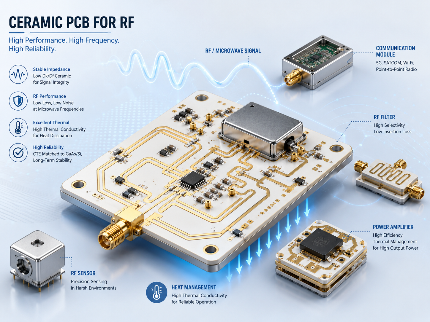
Ceramic PCB for RF modules, microwave filters, sensors, and power amplifiers

In RF and microwave applications, the substrate is part of the electrical design. It affects impedance, insertion loss, resonance behavior, signal phase, and long-term stability. This is why engineers often consider ceramic PCB substrate options such as alumina PCB for RF modules, microwave circuits, filters, sensors, power amplifiers, and hybrid circuits.

Why Ceramic PCB Substrate Matters in RF Circuits?

A ceramic PCB substrate matters in RF circuits because high-frequency signals are sensitive to material behavior. Small changes in dielectric constant, trace geometry, surface quality, or substrate thickness can shift impedance and affect performance.

For buyers, the key point is simple: RF ceramic PCB is not selected only for heat dissipation. The material must support stable signal behavior at the target frequency. A supplier must understand both ceramic PCB manufacturing and the RF requirements behind the drawing.

Key RF Properties: Dielectric Constant, Loss Tangent, and Dimensional Stability

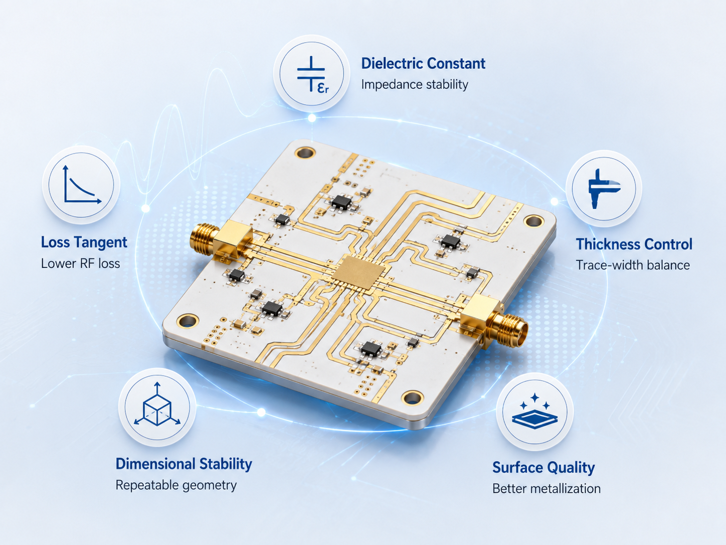
For RF ceramic PCB projects, three material properties usually matter most: dielectric constant, loss tangent, and dimensional stability.

Ceramic PCB for RF modules, microwave filters, sensors, and power amplifiers
RF PropertyWhy It MattersBuyer Note
Dielectric constantAffects impedance, wavelength, trace width, and circuit sizeConfirm the value required by the RF design, not only the material name
Loss tangentAffects signal loss at high frequencyLower loss is more important as frequency increases
Substrate thicknessAffects impedance and manufacturable line widthKeep thickness controlled and clearly specified
Dimensional stabilityHelps maintain trace geometry and circuit repeatabilityImportant for filters, antennas, resonators, and microwave circuits
Surface qualityAffects metallization and high-frequency current behaviorReview finish and metallization process early

A good RF ceramic PCB quote should not start with “Can you make ceramic PCB?” It should start with frequency range, impedance target, material requirement, line width, tolerance, and metallization needs.

Common Materials: Alumina PCB, AlN, Rogers, and FR4

Material choice depends on frequency, loss target, thermal demand, cost, and manufacturing method. Alumina PCB is common in RF ceramic substrate applications, but it is not the only option.

MaterialRF StrengthLimitationBest Use
Alumina PCBStable ceramic substrate, good mechanical and thermal behavior, widely used in RF and hybrid circuitsHigher dielectric constant than many organic RF laminates; design must account for itRF modules, microwave circuits, sensors, hybrid circuits
Aluminum nitride PCBBetter thermal conductivity than aluminaHigher cost; not always needed for RF unless heat is also a major issueRF power modules, high-power microwave circuits, compact thermal designs
Rogers / PTFE-based RF laminateCommon for RF PCB design, lower-loss options availableMaterial and processing cost can be higher than FR4; thermal/mechanical behavior differs from ceramicAntennas, RF boards, microwave circuits, communication devices
FR4Low cost and easy to manufactureLoss and dielectric variation become problematic at higher frequenciesLow-frequency or cost-sensitive circuits where RF loss is acceptable

For many RF ceramic PCB projects, alumina PCB is selected when the design needs ceramic stability, precision metallization, and reliable high-frequency behavior in a compact substrate.

Ceramic PCB for RF vs Standard RF PCB Materials

The decision between ceramic PCB and standard RF laminate depends on circuit function, frequency, power level, size, and reliability environment.

OptionAdvantageLimitationBetter Fit
Ceramic PCB for RFStable substrate, good thermal behavior, suitable for hybrid and precision circuitsHigher cost and stricter manufacturing limitsRF modules, microwave packages, high-stability circuits
Rogers RF PCBMature RF laminate option with known dielectric choicesNot ceramic; thermal and mechanical behavior differAntennas, RF communication boards, microwave PCB layouts
FR4 RF designLow cost and fast productionHigher loss and less predictable dielectric behavior at high frequencyLow-frequency RF, simple prototypes, cost-sensitive products
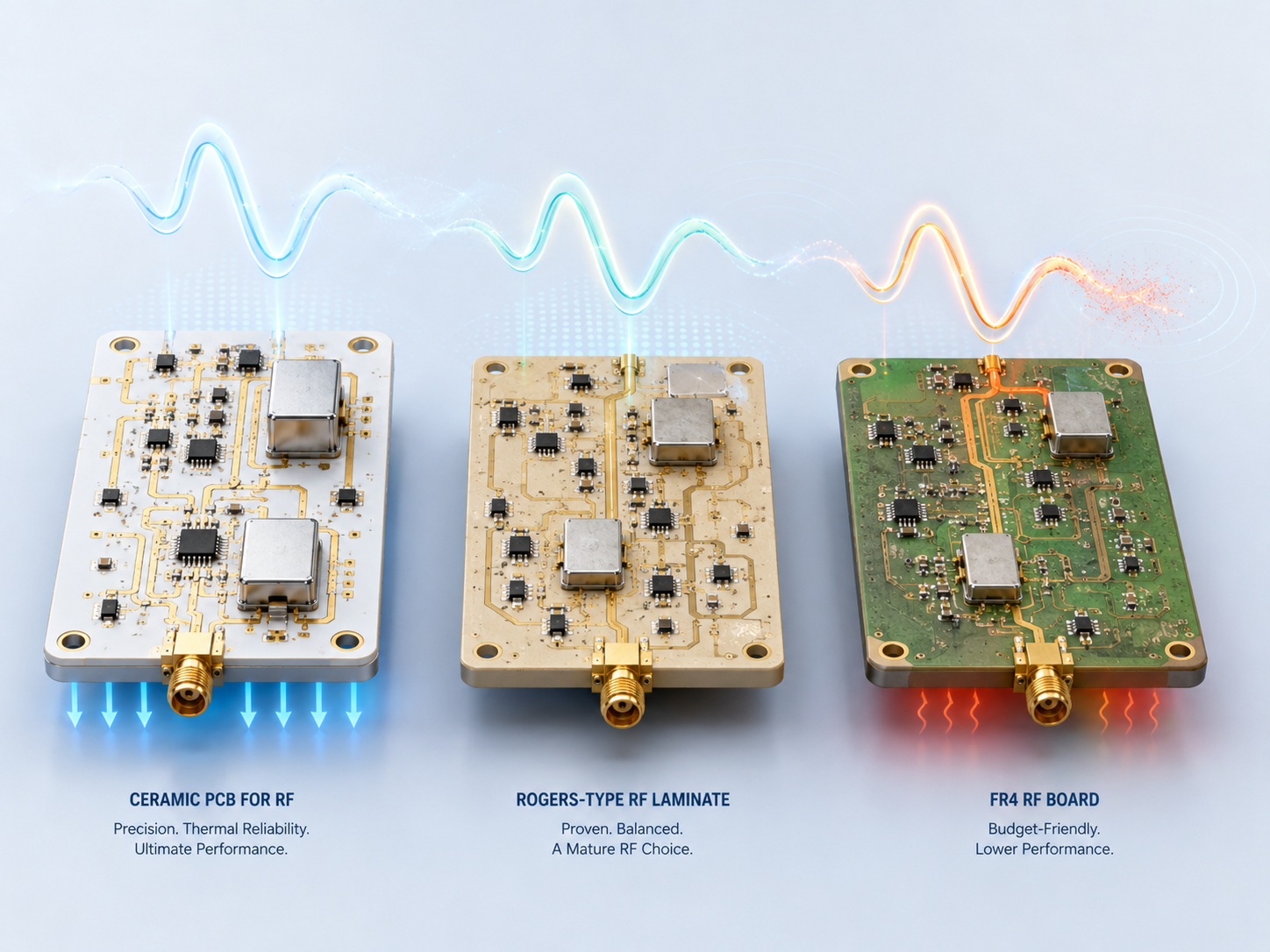
RF performance comparison between ceramic PCB, Rogers laminate, and FR4 board

The practical takeaway: use FR4 only when RF loss and dielectric variation are acceptable. Use Rogers-type RF laminates for many standard RF boards. Use ceramic PCB when the design needs ceramic stability, compact structure, precision, or stronger thermal reliability.

Ceramic PCB Manufacturing Considerations for RF Applications

Ceramic PCB manufacturing for RF applications must control the details that affect signal performance. A small trace width error may be more serious in RF than in a normal power or control PCB.

Important manufacturing points include:

  • Substrate material and thickness control
  • Fine line and spacing capability
  • Metallization method, such as thick film, thin film, DBC, or other suitable process
  • Copper or conductor thickness
  • Surface roughness and finish
  • Dimensional tolerance
  • Via and hole quality if required
  • Flatness and warpage
  • Pattern registration
  • Cleanliness and handling

For RF ceramic PCB manufacturing, the supplier should review whether the requested geometry is manufacturable before production. If the layout uses very fine traces, tight impedance targets, or microwave structures, early engineering communication reduces prototype failure risk.

When Should You Choose Alumina PCB for RF?

Choose alumina PCB for RF when the circuit needs a stable ceramic substrate, good dimensional control, and reliable behavior in a compact or harsh environment.

Alumina PCB is often suitable for:

  • RF hybrid circuits
  • Microwave modules
  • Sensor circuits
  • Thin film or thick film RF substrates
  • Filters and matching networks
  • High-temperature or high-reliability electronics
  • Compact modules where ceramic stability is useful

Alumina may be unnecessary if the circuit can meet RF performance with a standard RF laminate at lower cost. It may also be the wrong choice if the design requires a different dielectric constant, lower loss material, or stronger thermal conductivity than alumina can provide.

Common Design and Purchasing Mistakes

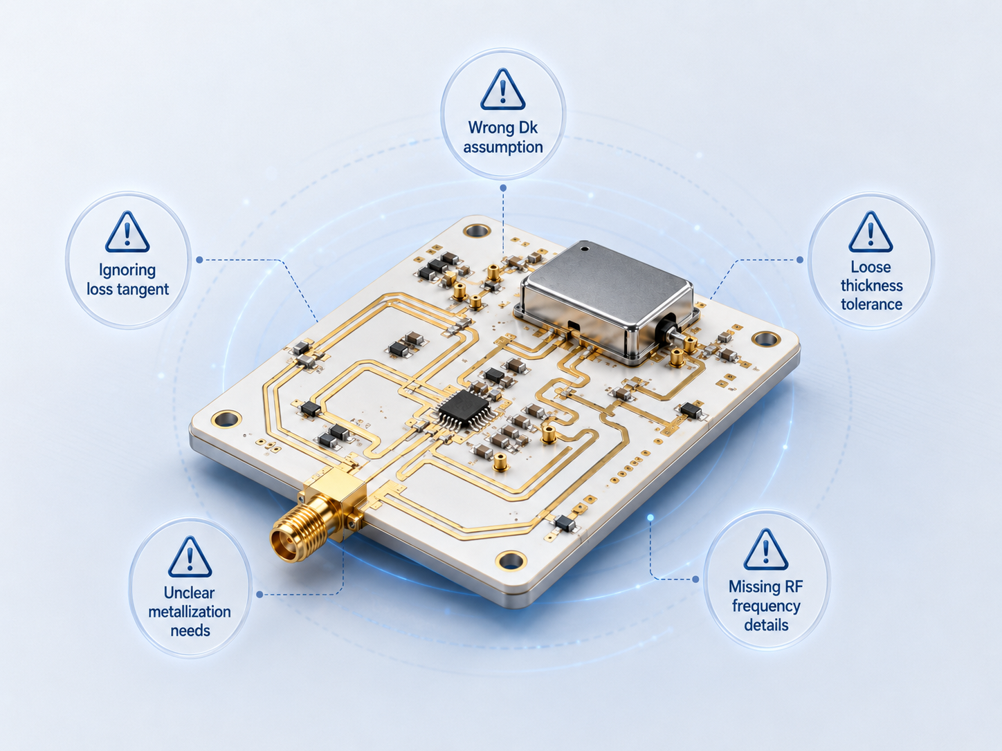
The most common mistake is treating RF ceramic PCB like a normal ceramic circuit board. RF performance depends on both material and geometry.

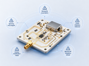
Common RF ceramic PCB mistakes including incorrect dielectric constant, loose tolerance, and missing frequency details
MistakeWhy It Causes ProblemsBetter Approach
Only asking for “ceramic PCB for RF”Supplier cannot confirm material, frequency, or processProvide frequency range, substrate material, and circuit function
Ignoring dielectric constantImpedance and trace width may shiftSpecify target dielectric constant or approved material
Ignoring loss tangentHigh-frequency loss may become unacceptableDefine frequency and acceptable RF performance
Using vague tolerancesRF traces may not match design intentSpecify line width, spacing, substrate thickness, and dimensional tolerance
Choosing alumina automaticallyAlumina may not fit every RF designCompare alumina, AlN, Rogers, and FR4 based on real requirements
Sending only GerbersSupplier cannot judge RF function or riskInclude stackup, material notes, impedance targets, and application context

A good ceramic PCB manufacturer should ask technical questions before quotation if the RF requirements are unclear.

How to Choose a Ceramic PCB Manufacturer for RF Projects?

A ceramic PCB manufacturer for RF projects should be evaluated by engineering communication, material control, metallization capability, and tolerance control, not only by price.

Useful supplier checks include:

  • Experience with RF or microwave ceramic substrate projects
  • Ability to manufacture alumina PCB and other ceramic PCB substrate types
  • Clear process options for thin film, thick film, or metallized ceramic circuits
  • Fine line and spacing capability
  • Substrate thickness and dimensional tolerance control
  • Inspection process for metallization, surface finish, and pattern accuracy
  • Willingness to review drawings before quoting
  • Ability to support prototypes before mass production
  • Clear communication about manufacturing limits and alternatives

For EBest Circuit (Best Technology), RF ceramic PCB review should focus on whether the drawing, material, tolerance, and production method match the actual frequency and application requirement.

What to Provide When Requesting an RF Ceramic PCB Quote

A complete RFQ helps the supplier evaluate manufacturability, cost, and performance risk before production.

Provide these details when requesting a ceramic PCB quote:

  • Application type, such as RF module, microwave circuit, sensor, or power amplifier
  • Frequency range
  • Ceramic material preference, such as alumina PCB or AlN
  • Required dielectric constant if specified
  • Loss requirement if specified
  • Substrate dimensions and thickness
  • Line width and spacing
  • Metallization method or conductor requirement
  • Copper or metal thickness
  • Surface finish
  • Hole, via, or edge requirements
  • Dimensional tolerance
  • Quantity for prototype and mass production
  • Test or inspection requirements
  • Gerber files, drawings, and stackup notes

If the project is still in early design, provide the target frequency, operating environment, and performance concern. This allows the ceramic PCB manufacturer to suggest practical material and process options before the design is locked.

FAQ

Is ceramic PCB good for RF?

Yes. Ceramic PCB can be good for RF when the circuit needs dielectric stability, dimensional accuracy, thermal reliability, and compact substrate design. It is especially useful for RF modules, microwave circuits, hybrid circuits, sensors, and high-reliability electronics.

Why is alumina PCB used in RF circuits?

Alumina PCB is used in RF circuits because it provides a stable ceramic substrate, good mechanical strength, useful thermal behavior, and compatibility with thin film or thick film metallization. It is common in RF and microwave hybrid circuits.

Is ceramic PCB better than Rogers PCB for RF?

Not always. Rogers-type RF laminates are widely used for RF PCB designs, antennas, and microwave boards. Ceramic PCB is better when the design needs ceramic stability, compact substrate behavior, precision metallization, or stronger thermal/mechanical reliability.

Can FR4 be used for RF circuits?

FR4 can be used for lower-frequency or cost-sensitive RF circuits, but it becomes less predictable as frequency increases. Loss, dielectric variation, and tolerance control can limit performance in higher-frequency RF designs.

What affects RF performance in ceramic PCB manufacturing?

RF performance can be affected by dielectric constant, loss tangent, substrate thickness, line width, spacing, metallization quality, surface roughness, dimensional tolerance, and pattern registration.

What is the difference between alumina PCB and AlN PCB for RF?

Alumina PCB is commonly used for RF ceramic substrates and is usually more cost-effective. AlN PCB offers higher thermal conductivity, so it is useful when the RF circuit also has significant heat dissipation requirements.

What should I ask a ceramic PCB manufacturer before ordering?

Ask about material options, RF project experience, fine line capability, metallization process, substrate thickness tolerance, dimensional tolerance, inspection method, prototype support, and whether they can review RF-related drawing requirements before production.

Do I need impedance control for ceramic PCB for RF?

Many RF ceramic PCB designs need impedance awareness, even if the supplier does not provide full RF simulation. At minimum, the buyer should provide frequency range, trace geometry, substrate thickness, dielectric requirement, and critical RF areas.

Conclusion

A ceramic PCB for RF is not just a ceramic version of a normal PCB. The substrate affects impedance, signal loss, circuit size, stability, and long-term performance. Alumina PCB is often a practical RF ceramic substrate, while AlN, Rogers materials, and FR4 each fit different design conditions.

If you are evaluating ceramic PCB substrate options, alumina PCB, ceramic PCB manufacturing, or RF PCB prototype support, EBest Circuit (Best Technology) can help review your drawings, material requirements, tolerance needs, and quotation details. Contact us at sales@bestpcbs.com.
You may also like

Ceramic Core PCB | Alumina & Aluminum Nitride Ceramic PCB
Monday, May 11th, 2026

What is a ceramic core PCB?

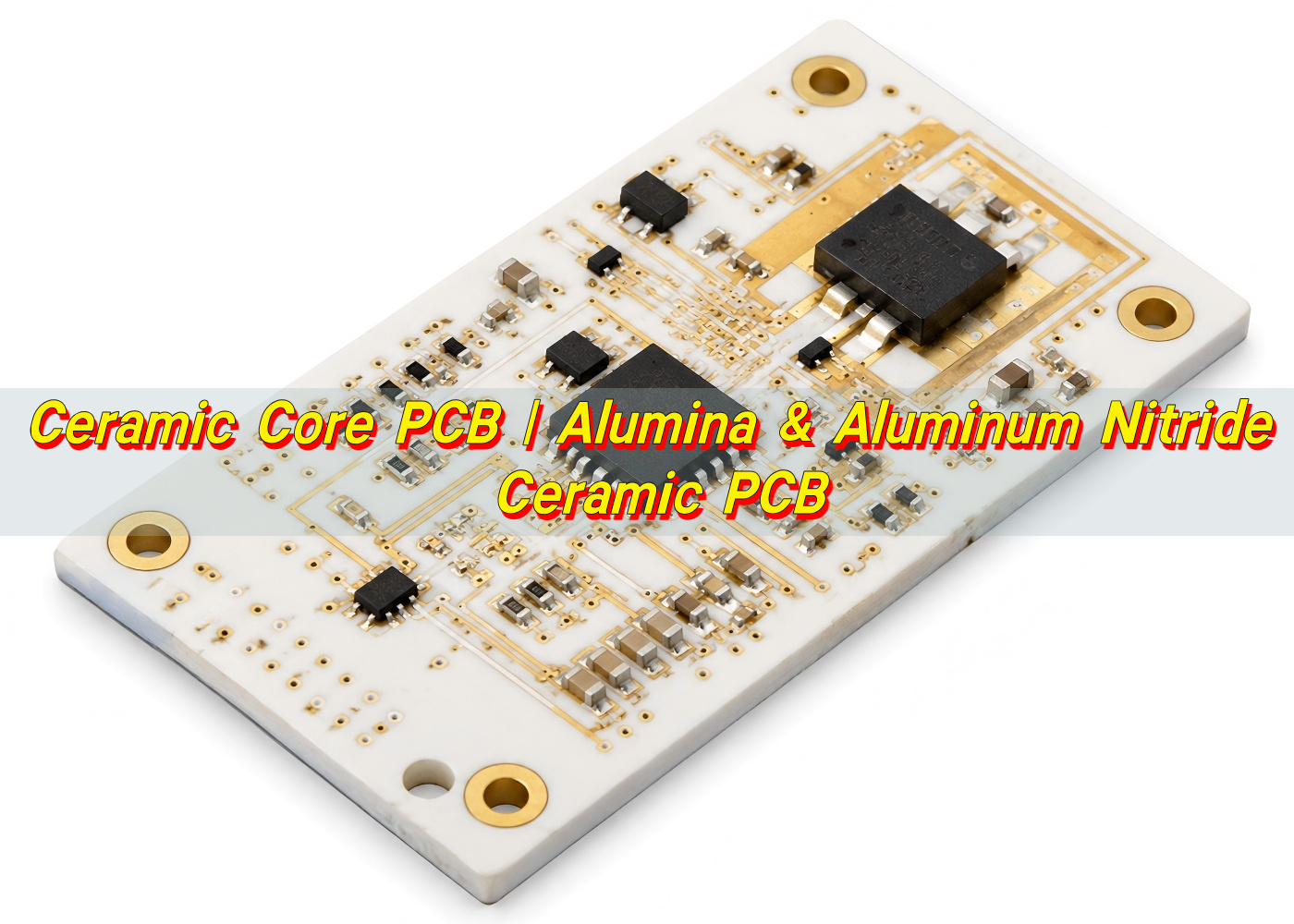
Ceramic core PCB is a printed circuit board built on a ceramic substrate instead of a conventional organic laminate such as FR4. In this type of board, the ceramic layer works as the main supporting base and thermal pathway. It gives the circuit strong heat transfer, stable electrical insulation, and excellent dimensional consistency under demanding operating conditions.
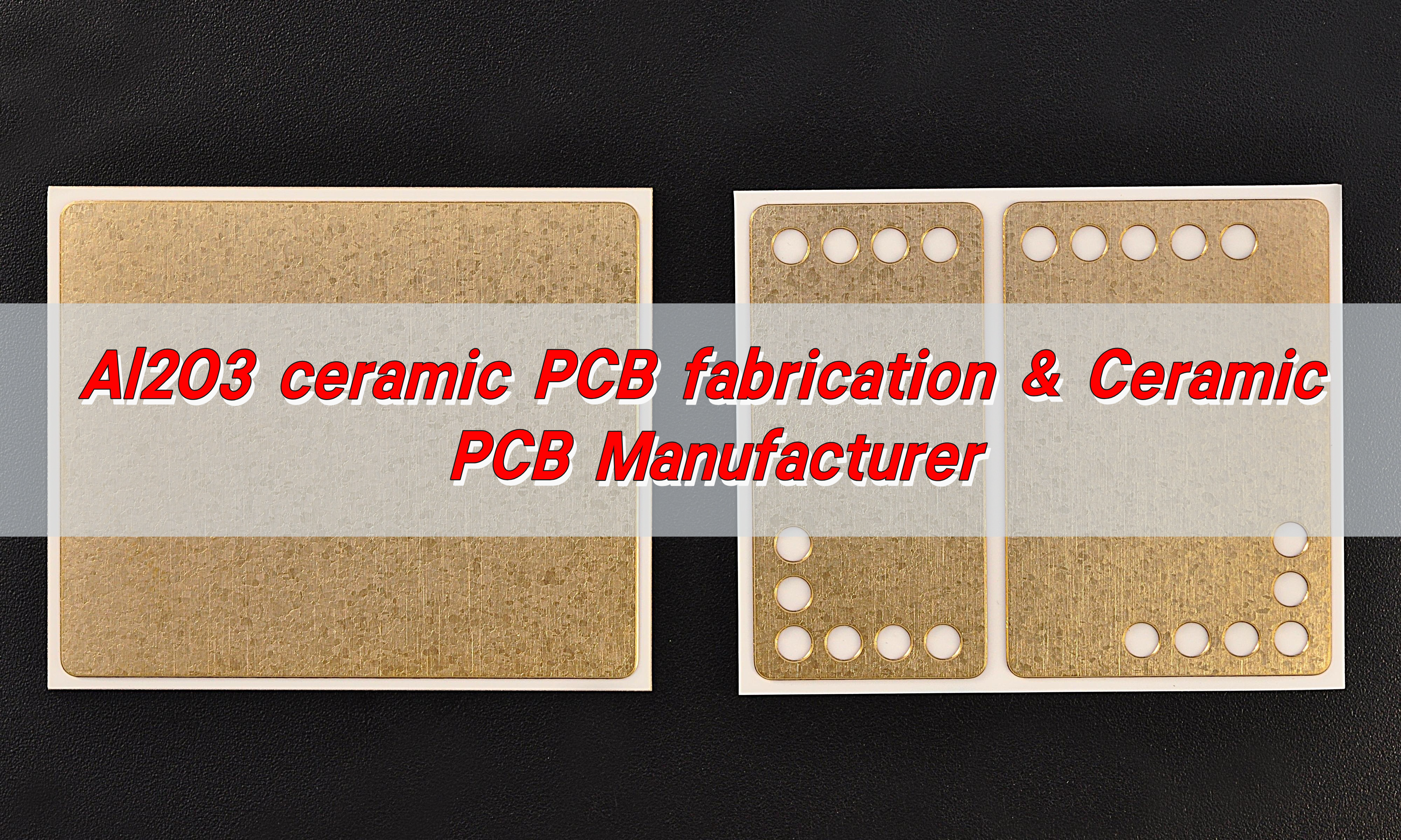
Unlike standard PCB materials that rely on glass fiber and resin, ceramic PCB boards use inorganic ceramic materials such as alumina, aluminum nitride, or silicon nitride. These materials are valued in high-power, high-frequency, high-temperature, and high-reliability electronics.

In the PCB industry, ceramic core PCB is often used for applications where ordinary laminates cannot provide enough thermal conductivity or long-term stability. The board may support thick copper, thin-film circuits, DPC copper plating, DBC bonding, or AMB structures, depending on the electrical and mechanical requirements of the project.

EBest Circuit (Best Technology) supports ceramic PCB manufacturing for engineers who need more than a basic circuit board. With experience in alumina PCB, aluminum nitride PCB, DPC ceramic PCB, DBC ceramic substrate, AMB ceramic substrate, and customized ceramic PCB boards, EBest Circuit helps customers move from early design review to production with practical engineering support.

What is the difference between ceramic and FR4?

Ceramic PCB and FR4 PCB are both widely used in electronics, but they are designed for different performance levels. FR4 is the most common PCB substrate because it is cost-effective, easy to process, and suitable for many consumer, industrial, and general electronic products. Ceramic PCB is selected when the circuit needs higher thermal conductivity, better temperature resistance, and stronger dimensional stability.

FR4 is made from woven fiberglass cloth and epoxy resin. It performs well in standard electronic assemblies, but its thermal conductivity is limited. Ceramic boards, by contrast, use inorganic ceramic substrates that conduct heat much more efficiently while keeping excellent insulation. This is why ceramic core PCB is commonly found in LED modules, laser equipment, power electronics, sensors, medical devices, automotive electronics, and aerospace-related systems.

ItemCeramic Core PCBFR4 PCB
Main materialAlumina, aluminum nitride, silicon nitride, or other ceramic materialsGlass fiber reinforced epoxy laminate
Thermal conductivityHigh, suitable for heat-sensitive and power applicationsLow to moderate, suitable for general electronics
Temperature resistanceExcellent stability at elevated temperaturesGood for standard operating environments
Mechanical behaviorHard, stable, and rigid, but requires careful handlingTougher and more flexible during standard assembly
Electrical insulationVery strong insulation performanceReliable insulation for common circuit designs
Typical applicationsHigh-power LEDs, RF modules, power devices, sensors, automotive electronicsConsumer electronics, control boards, communication devices, general PCBA
Cost levelHigher due to material and process complexityLower and highly scalable

The choice should not be based only on price. If the circuit generates a high amount of heat or must keep stable performance in a harsh environment, ceramic PCB can provide a stronger technical foundation.

What’s the difference between alumina PCB and aluminum nitride PCB?

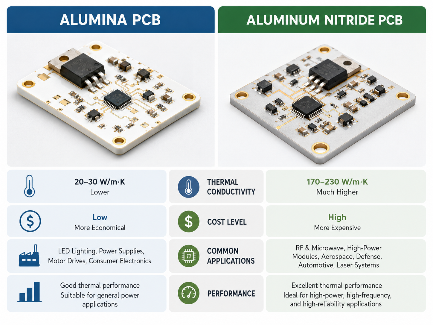
Alumina PCB and aluminum nitride PCB are two of the most common ceramic PCB materials. Both provide good insulation, stable structure, and better thermal performance than FR4. The key difference is thermal conductivity. Alumina is widely used because it offers a balanced combination of price, process maturity, and electrical performance. Aluminum nitride is chosen when the design needs much higher heat dissipation.

Alumina PCB usually refers to ceramic boards made from aluminum oxide. Common grades include 96% alumina and 99.6% alumina. It is a practical choice for many LED, sensor, power module, and industrial electronic applications. It has good mechanical strength, stable electrical insulation, and a more accessible ceramic board price compared with aluminum nitride.

Aluminum nitride PCB is often used in more demanding thermal designs. Its thermal conductivity can be several times higher than alumina, making it highly suitable for power semiconductors, high-brightness LEDs, laser diodes, automotive power modules, and compact high-power assemblies. It is usually more expensive than alumina because the raw material, sintering process, and manufacturing control are more demanding.

ItemAlumina PCBAluminum Nitride PCB
MaterialAluminum oxide ceramicAluminum nitride ceramic
Thermal conductivityGood, commonly used for medium to high thermal needsExcellent, suitable for high-power heat dissipation
CostMore economical among ceramic PCB optionsHigher due to material and process requirements
Mechanical strengthStrong and mature in productionStrong, with careful process control needed
Electrical insulationExcellentExcellent
Typical useLED modules, sensors, heaters, industrial controls, power circuitsPower modules, laser devices, high-power LEDs, RF and automotive electronics

EBest Circuit can help customers compare ceramic PCB materials during DFM review, so the final design matches both technical needs and production cost targets.

Why use ceramic PCB?

Ceramic PCB is used because it solves several practical engineering problems at the same time. It helps remove heat, keeps circuits electrically insulated, supports high-density layouts, and performs well in high-temperature environments.

One of the strongest reasons to use ceramic PCB is thermal management. As electronic products become smaller and more powerful, heat has less room to escape. If heat remains around chips, LEDs, or power components, performance can drop over time. A ceramic board gives heat a faster path away from the source, helping the assembly work in a more stable condition.

Ceramic PCB also supports excellent electrical properties. It can provide low dielectric loss, high insulation resistance, and stable performance across demanding operating conditions. This is important for RF circuits, sensor modules, high-voltage electronics, and power devices.

  • High thermal conductivity for better heat spreading
  • Strong electrical insulation for compact circuit layouts
  • Excellent temperature resistance for harsh environments
  • Stable dimensions during thermal cycling
  • Good compatibility with power devices, LEDs, sensors, and RF modules
  • Long service life in high-reliability electronic products

For manufacturers, ceramic PCB also brings value in quality consistency. The substrate has stable physical properties, which helps reduce performance drift in precision electronics. For engineers, it allows a cleaner thermal design and can reduce the need for bulky heat sinks in some compact products.

How much does a ceramic PCB cost?

Ceramic PCB cost is usually higher than standard FR4 PCB cost because the material, processing method, copper bonding, laser drilling, metallization, and quality control are more specialized. In high-power or high-reliability products, better heat transfer and longer operating stability can reduce the risk of field problems and improve product performance.

The ceramic board price depends on several technical factors. Material selection is one of the biggest cost drivers. Alumina PCB is generally more economical, while aluminum nitride PCB costs more because it provides much higher thermal conductivity. Board size, thickness, copper thickness, circuit precision, via structure, surface finish, tolerance control, and production quantity also affect the final quotation.

Cost FactorHow It Affects Ceramic PCB Cost
Ceramic materialAlumina is usually more economical; aluminum nitride is higher in cost but stronger in thermal performance.
Board sizeLarger ceramic boards use more raw material and may require tighter handling control.
Substrate thicknessSpecial thickness requirements may increase material preparation and processing cost.
Copper thicknessThicker copper improves current capacity but increases plating or bonding complexity.
Line width and spacingFine circuits require more precise manufacturing control.
Via structureFilled vias, laser vias, and conductive vias can raise process complexity.
Surface finishENIG, immersion silver, nickel gold, or other finishes may affect pricing.
Order quantityPrototype cost per piece is higher; batch production usually improves unit cost.

For a reliable ceramic PCB quotation, engineers should provide Gerber files, drawings, material requirements, board thickness, copper thickness, surface finish, tolerance needs, and expected quantity. If the design is still being evaluated, EBest Circuit can review the technical requirements and suggest a practical manufacturing route before final pricing.

Can ceramic core PCB be customized in size and layout?

Yes, ceramic core PCB can be customized in size, layout, thickness, copper pattern, surface finish, and structure. Customization is one of the main reasons ceramic PCB is used in advanced electronic products.

Custom ceramic PCB does require careful design planning. Ceramic materials are hard and stable, but they are processed differently from FR4. Features such as hole size, edge shape, slot position, via design, copper thickness, and board outline should be reviewed before production. A strong DFM check helps improve manufacturability and keeps the finished board aligned with the original electrical and thermal goals.

Common customization options include:

  • Alumina PCB or aluminum nitride PCB substrate selection
  • Custom board outline, size, and ceramic thickness
  • Single-sided, double-sided, or multilayer ceramic PCB structure
  • Thin-film or thick-film circuit design
  • DPC, DBC, or AMB ceramic core manufacturing process
  • ENIG, nickel gold, silver, or other surface finish options
  • Laser drilling, via filling, and precision routing
  • Thick copper design for higher current carrying capacity

EBest Circuit works with customers on customized ceramic PCB projects where standard PCB materials may not deliver enough thermal or mechanical stability. The engineering team can assist with material selection, stack-up review, ceramic core manufacturing process evaluation, and production feasibility checks.

How are ceramic cores made?

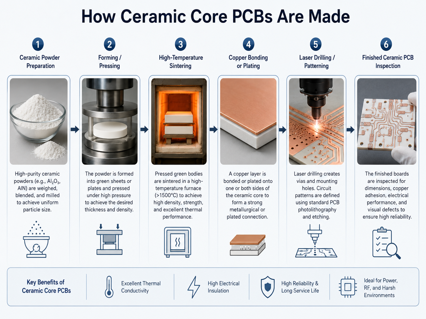
Ceramic cores are made through a controlled process that starts with ceramic powder preparation and ends with a dense, stable substrate suitable for circuit formation. The exact process depends on the material and final PCB structure.

In a typical ceramic substrate process, ceramic powder is mixed with binders and additives to form a workable material. The material is shaped into sheets or pressed forms, then dried and sintered at high temperature. Sintering gives the ceramic its hardness, density, and stable physical properties. After that, the substrate may be lapped, polished, laser drilled, metallized, plated, etched, and finished according to the PCB design.

For circuit formation, different ceramic PCB technologies can be used. DPC, or Direct Plated Copper, is often chosen for fine circuits and high-precision designs. DBC, or Direct Bonded Copper, bonds copper directly onto the ceramic surface and is often used for power modules. AMB, or Active Metal Brazing, provides very strong bonding and is suitable for high-reliability power electronics.

Process TypeMain FeatureTypical Application
DPC ceramic PCBUses copper plating technology for fine circuits and precision patternsLED modules, sensors, optical devices, high-density ceramic circuits
DBC ceramic PCBDirect copper bonding provides strong thermal and current capacityPower modules, IGBT substrates, high-power electronics
AMB ceramic PCBActive brazing creates strong copper-to-ceramic bondingAutomotive power modules, high-reliability energy electronics
Thick-film ceramic PCBConductive paste is printed and fired onto ceramicHeaters, sensors, hybrid circuits, industrial modules
Thin-film ceramic PCBHigh-precision metal layers are deposited on ceramicMicrowave circuits, precision sensors, RF electronics

A professional ceramic PCB manufacturer must control material quality, sintering conditions, copper adhesion, surface flatness, circuit accuracy, and inspection standards. EBest Circuit combines process knowledge with practical PCB engineering support, helping customers choose the right ceramic core manufacturing process for the final product environment.

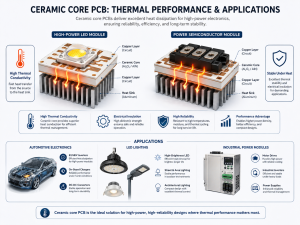
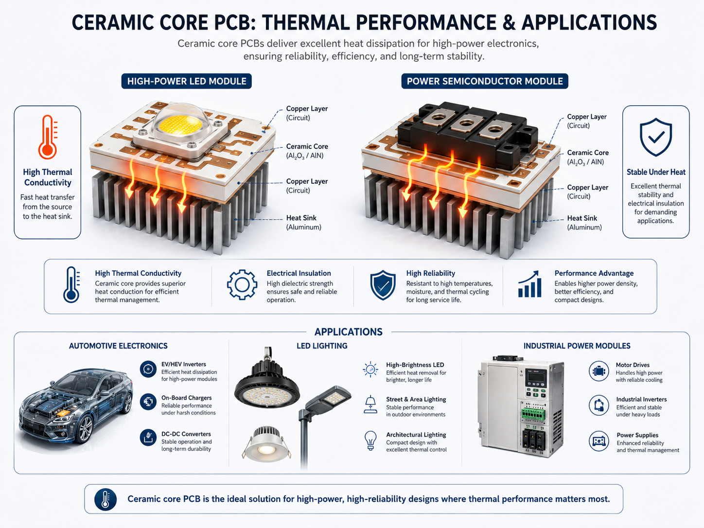
What thermal performance does ceramic core PCB deliver?

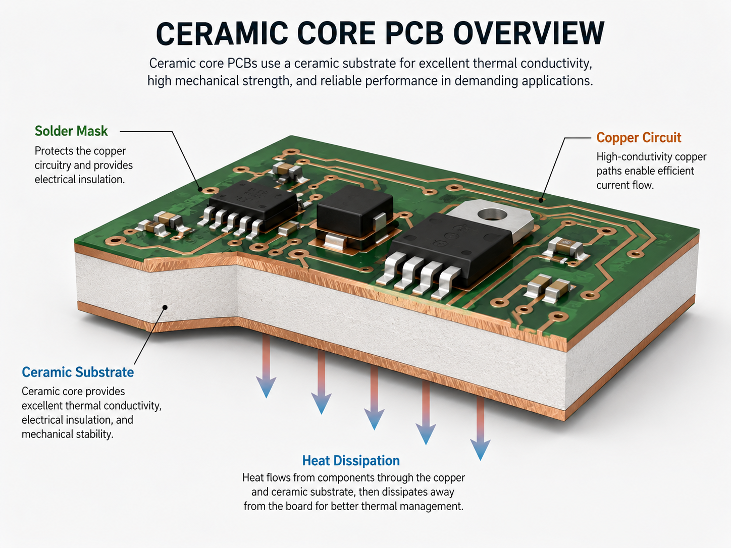
Ceramic core PCB delivers much stronger thermal performance than standard FR4 boards. The main advantage is that ceramic materials can transfer heat efficiently while still providing electrical insulation.

Alumina PCB offers good thermal conductivity for many industrial and LED applications. Aluminum nitride PCB provides a much higher level of heat transfer and is often used where thermal density is more demanding. With the right copper thickness, layout, and mounting structure, ceramic PCB boards can move heat away from components quickly and help maintain stable operating temperatures.

Thermal performance is not only about the ceramic material itself. The final result also depends on copper design, substrate thickness, dielectric path, via structure, solder joint quality, component placement, and heat sink contact.

MaterialGeneral Thermal PerformanceBest-Fit Applications
FR4Limited thermal conductivityGeneral electronics and low-to-medium power circuits
Alumina ceramicGood thermal conductivity with balanced costLEDs, sensors, industrial modules, moderate power electronics
Aluminum nitride ceramicExcellent thermal conductivityHigh-power LEDs, laser modules, power semiconductors, automotive electronics
Silicon nitride ceramicStrong thermal and mechanical reliabilityHigh-reliability power modules and harsh operating environments

For thermal-sensitive designs, EBest Circuit can support layout review and material comparison. This is helpful when customers need to decide between alumina PCB and aluminum nitride PCB, or when they want to optimize the balance between ceramic PCB cost, heat dissipation, and long-term reliability.

What are ceramic cores used for?

Ceramic cores are used in electronic products that need better thermal control, high insulation, stable structure, and reliable performance under demanding conditions. They are especially useful where compact size and high power must coexist. Because ceramic materials can transfer heat efficiently while maintaining electrical separation, they are widely used in modern power, lighting, automotive, medical, and communication systems.

In LED products, ceramic PCB helps move heat away from LED chips and supports stable brightness. In power electronics, ceramic substrates are used for modules that handle high current and high voltage. In RF and microwave circuits, ceramic materials can provide stable electrical characteristics. In medical and aerospace electronics, ceramic PCB boards support reliability, precision, and long service life.

  • High-power LED modules and lighting engines
  • Laser diode modules and optical devices
  • Power semiconductor packages and IGBT modules
  • Automotive electronics and electric vehicle power modules
  • RF, microwave, and communication circuits
  • Medical sensors and monitoring devices
  • Industrial control modules and high-temperature electronics
  • Aerospace, UAV, and high-reliability electronic assemblies

Ceramic core PCB is a strong choice when the product needs more than ordinary PCB performance. Alumina PCB is suitable for balanced thermal and cost requirements, while aluminum nitride PCB is ideal for stronger heat dissipation. For custom ceramic PCB boards, ceramic PCB materials, ceramic PCB cost evaluation, and ceramic core manufacturing process support, EBest Circuit (Best Technology) can help engineers build a practical path from prototype to production.

Summary:

Ceramic core PCB is not simply a premium version of FR4. It is a specialized circuit platform for products that need excellent heat transfer, high insulation, stable operation, and compact design. If your project requires alumina PCB, aluminum nitride PCB, or custom ceramic PCB manufacturing support, you can contact sales@bestpcbs.com for project discussion and quotation support.

You may also like

Al2O3 Ceramic PCB Fabrication & Ceramic PCB Manufacturer
Tuesday, March 4th, 2025

Al2O3 ceramic PCB fabrication is the process of producing printed circuit boards using alumina (Al2O3) ceramic substrates. Alumina ceramics have high mechanical strength, hardness, heat resistance, electrical insulation and corrosion resistance, and are one of the most cost-effective materials in the electronic packaging industry.

Al2O3 Ceramic PCB Fabrication & Ceramic PCB Manufacturer

Unlike ordinary PCBs, ceramic PCBs are made by directly bonding copper foil and ceramic substrates under high temperature environments. They have strong bonding strength, the copper foil will not fall off, and have high reliability and performance stability under high temperature and high humidity environments.

As a ceramic PCB manufacturer with 18 years of manufacturing experience, BEST Technology has accumulated rich professional strength in the manufacturing of alumina ceramic PCBs. In terms of manufacturing technology, it adopts advanced manufacturing processes to ensure that each alumina ceramic PCB meets high quality standards.

What is Alumina Ceramic PCB?

Alumina ceramic PCBs are circuit boards made using aluminum oxide (Al₂O₃) as the substrate material. This type of PCB is known for its excellent thermal management, high insulation resistance, and mechanical strength.

Compared to conventional FR-4 boards, alumina ceramic PCBs offer better heat dissipation, making them ideal for high-power applications like LED lighting, automotive electronics, and aerospace systems.

Unlike standard PCB materials, alumina ceramic is highly resistant to chemical corrosion and environmental stress. It can endure extreme temperatures without degrading, ensuring long-term reliability in demanding conditions.

How Do You Make Al₂O₃ Ceramic PCB?

Fabricating an alumina ceramic PCB requires a specialized manufacturing process. Unlike FR-4 boards, which are processed using laminates, ceramic PCBs are created through advanced sintering techniques.

The process typically involves:

  • Material Preparation – High-purity alumina ceramic is selected based on thermal and electrical requirements.
Al2O3 Ceramic PCB Fabrication & Ceramic PCB Manufacturer
  • Substrate Formation – The ceramic is shaped and sintered at high temperatures to achieve a dense, strong structure.
  • Metallization – Copper, silver, or gold is deposited onto the ceramic surface using thick-film or thin-film technology.
  • Circuit Patterning – The conductive layer is etched or laser-processed to define the circuit layout.
  • Component Assembly – SMD or through-hole components are mounted using high-temperature soldering or wire bonding.
  • Final Testing – The finished PCB undergoes electrical and thermal testing to ensure optimal performance.

This fabrication method results in a robust, high-performance PCB with excellent electrical insulation and thermal efficiency.

What Are the Advantages of Alumina Ceramic PCB?

Al₂O₃ ceramic PCBs come with a range of benefits that make them superior to traditional materials.

  • Exceptional Heat Dissipation – The ceramic substrate effectively transfers heat away from components, preventing overheating.
  • High Mechanical Strength – Alumina ceramic is incredibly strong, resisting mechanical stress and impact.
  • Superior Electrical Insulation – This material prevents electrical leakage, ensuring stable circuit performance.
  • Corrosion Resistance – Unlike metal-based PCBs, alumina ceramic does not rust or degrade over time.
  • Dimensional Stability – It maintains its structure under extreme conditions, including high temperatures and humidity.

These advantages make alumina ceramic PCBs a top choice for advanced electronic applications requiring reliability and efficiency.

What Are the Materials Used in Ceramic Substrate?

Ceramic PCBs can be made using different types of ceramics, each offering unique properties:

  • Alumina (Al₂O₃) – The most widely used ceramic material, known for its affordability and strong thermal performance.
Al2O3 Ceramic PCB Fabrication & Ceramic PCB Manufacturer
  • Aluminum Nitride (AlN) – Offers higher thermal conductivity than alumina but comes at a higher cost.
  • Beryllium Oxide (BeO) – Provides outstanding thermal properties but has limited use due to toxicity concerns.
  • Silicon Carbide (SiC) – Used in specialized high-temperature applications.

Each material is selected based on specific electrical, thermal, and mechanical requirements.

Is Alumina Ceramic Better Than Zirconia Ceramic?

Alumina and zirconia ceramics are both high-performance materials, but they serve different purposes.

  • Alumina Ceramic (Al₂O₃) – Offers better thermal conductivity, making it ideal for PCBs that require efficient heat dissipation.
  • Zirconia Ceramic (ZrO₂) – Has superior mechanical toughness and is often used in wear-resistant applications.

For electronic circuit boards, alumina is the preferred choice due to its balance of strength, electrical insulation, and heat management.

How Thick is Alumina Ceramic PCB?

The thickness of an alumina ceramic PCB varies based on application needs. Typically, the substrate thickness ranges from 0.25mm to 5mm, depending on thermal and mechanical requirements.

Thinner PCBs are used in compact electronics, while thicker substrates are chosen for heavy-duty applications requiring robust performance.

What is the Difference Between Al₂O₃ Ceramic PCB and FR-4?

FR-4 and alumina ceramic PCBs are widely used, but they differ in key ways:

  • Material CompositionFR-4 is a fiberglass-reinforced epoxy, while alumina ceramic is a solid ceramic substrate.
Al2O3 Ceramic PCB Fabrication & Ceramic PCB Manufacturer
  • Thermal Conductivity – Alumina ceramic dissipates heat much more efficiently than FR-4.
  • Durability – Ceramic PCBs can withstand harsh environments, whereas FR-4 boards are more prone to degradation.
  • Electrical Performance – Alumina has superior insulation and minimal signal loss, making it ideal for high-frequency circuits.

For applications where heat management and longevity are critical, alumina ceramic PCBs offer a clear advantage.

What Are the Applications of Alumina Ceramic PCB?

Due to their exceptional properties, alumina ceramic PCBs are used in various industries:

  • LED Lighting – Ensures efficient heat dissipation for high-brightness LEDs.
  • Power Electronics – Used in high-voltage circuits requiring stability and durability.
  • Automotive Electronics – Found in electric vehicles, sensors, and power management systems.
  • Aerospace & Defense – Used in radar, communication, and avionics due to reliability under extreme conditions.
  • Medical Devices – Integrated into imaging systems and surgical instruments for their biocompatibility and precision.

As electronic devices continue to demand higher efficiency and performance, alumina ceramic PCBs are becoming an essential part of modern technology.

Conclusion:

Al₂O₃ ceramic PCBs provide a superior solution for applications requiring durability, thermal efficiency, and electrical reliability. Compared to traditional FR-4 boards, they offer better heat dissipation, mechanical strength, and longevity.

For high-quality alumina ceramic PCB fabrication, choosing the right manufacturer is crucial. At EBest Circuit (Best Technology), we specialize in custom ceramic PCBs designed to meet the most demanding requirements. Contact us at sales@bestpcbs.com to discuss your project needs!

You may also like