PCB manufacturing PCB manufacturing
Home > Blog

ceramic printed circuit boards

Direct Printed Standing Ceramic Circuit Boards: What Should Engineers Know?
Thursday, June 11th, 2026

What Are Direct Printed Standing Ceramic Circuit Boards?

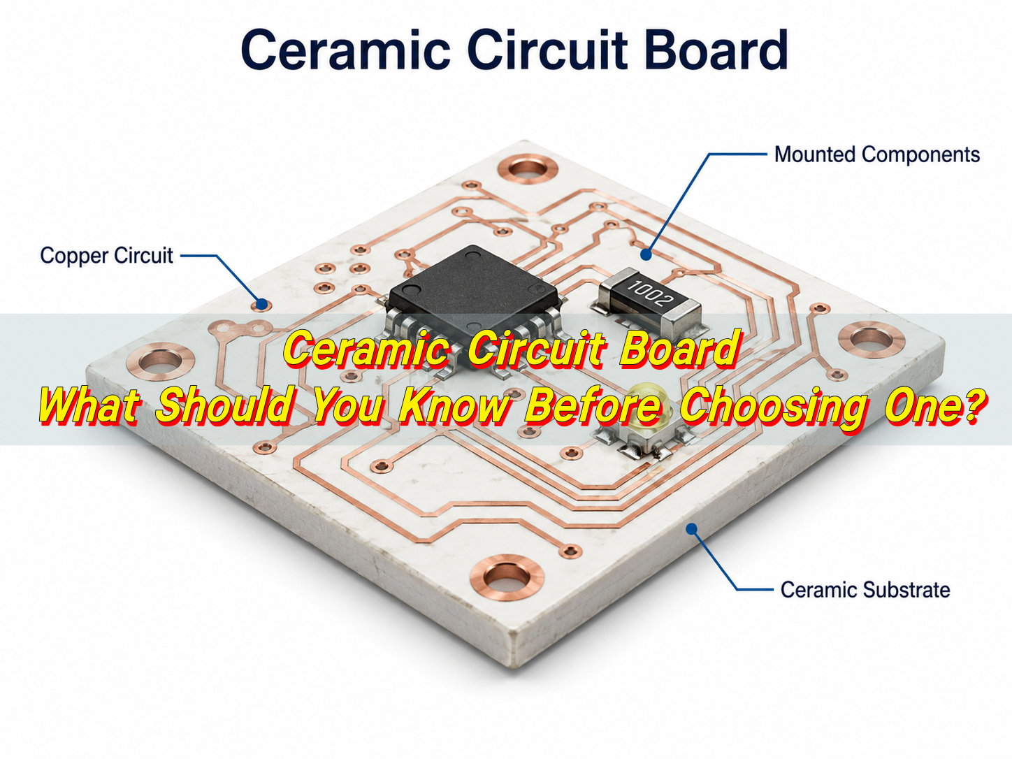
Direct printed standing ceramic circuit boards are ceramic-based circuit boards with conductive patterns formed directly on a ceramic substrate. They are used when a circuit must handle heat, electrical insulation, dimensional stability, and long service conditions better than a standard organic board can support.

Direct Printed Standing Ceramic Circuit Boards: What Should Engineers Know?

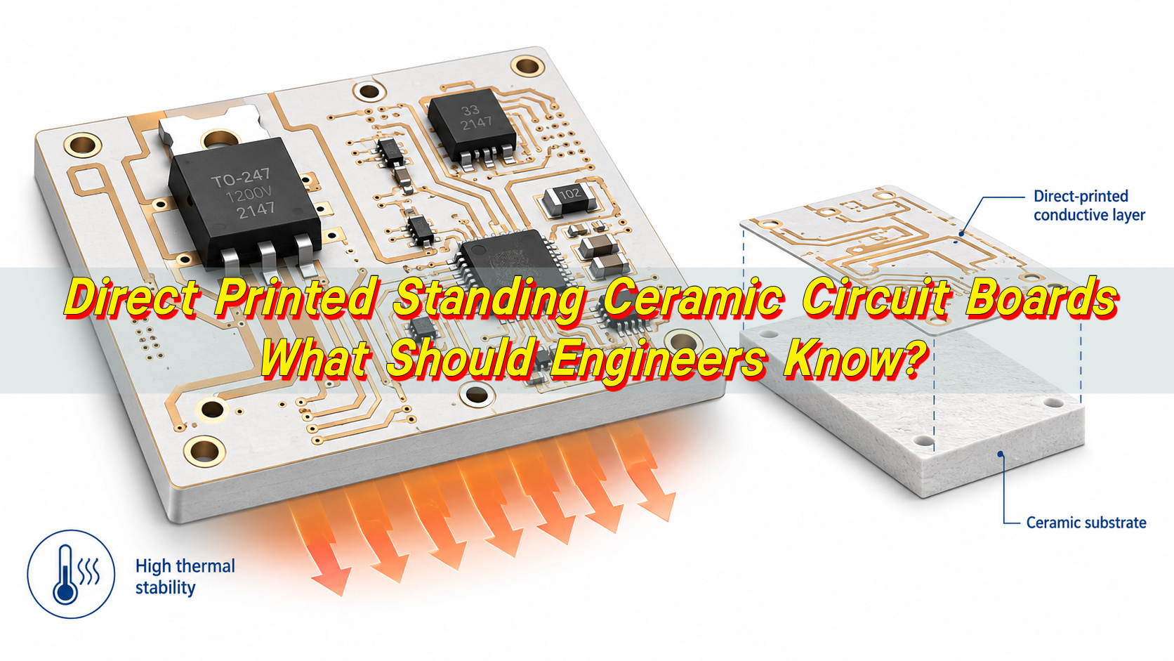
The phrase can sound unusual because it combines several technical ideas. “Ceramic circuit boards” refers to boards made with materials such as alumina, aluminum nitride, silicon nitride, LTCC, or HTCC ceramic. “Direct printed” refers to a manufacturing method where conductive materials are applied or built directly on the ceramic surface. “Standing” may describe a board mounted vertically, used as a compact support structure, or placed in a module where space is limited.

These boards are common in power electronics, LED modules, sensors, medical equipment, industrial controls, automotive electronics, and communication systems. In these applications, the board is not only a platform for components. It also helps manage heat, maintain insulation, and support stable electrical behavior.

A direct printed ceramic board may use thick-film printing, thin-film processing, DPC, DBC, AMB, LTCC, or HTCC technology. Each process has a different conductor system, line capability, copper thickness, cost level, and application range. Engineers should select the process according to power density, operating temperature, voltage, current, assembly method, and reliability targets.

For a successful project, design review should start before prototype production. EBest Circuit usually checks key items such as line width, board thickness, conductor material, layer count, silkscreen, glass glaze, and conductive layer material before proofing. This helps reduce avoidable design changes and keeps the prototype closer to the final production requirement.

What Is a Printed Circuit Board?

A printed circuit board, or PCB, is a board that supports and connects electronic components through designed conductive paths. These paths are usually made from copper. They replace loose wires with controlled traces, pads, vias, and layers, making electronic products smaller, cleaner, and easier to produce.

A standard PCB includes a base material, copper layers, solder mask, surface finish, vias, pads, and silkscreen. The base material provides support and insulation. Copper traces carry signals or current. Solder mask protects the copper and helps control soldering. Surface finish protects exposed pads and improves solderability. Vias connect different layers. Silkscreen provides component marks, polarity marks, logos, or assembly information.

Most rigid PCBs are made with FR4, a glass-reinforced epoxy laminate. FR4 is widely used because it offers a good balance of cost, insulation, mechanical strength, and process maturity. It works well for many control boards, communication modules, consumer electronics, industrial products, and general electronic assemblies.

A PCB may be supplied as a bare board or as a PCBA after component assembly. For ceramic projects, this distinction matters. A bare ceramic PCB is only the circuit substrate. A ceramic PCBA includes mounted components, soldering, inspection, and sometimes functional testing.

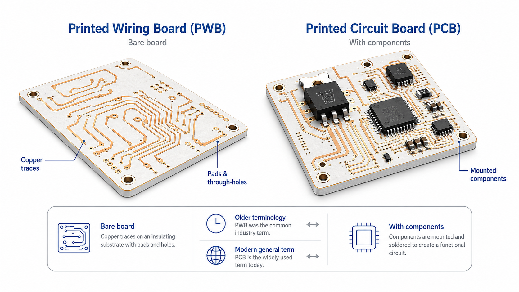
What Is the Difference Between a Printed Wiring Board and a Printed Circuit Board?

A printed wiring board, or PWB, usually refers to a bare board with conductive wiring patterns but without mounted components. A printed circuit board, or PCB, is the more common modern term and may refer to either a bare board or the general circuit board platform. In commercial electronics, PCB is used more often than PWB.

The terms are sometimes used interchangeably, but they are not always identical in technical documents. Older military, aerospace, and industrial documents may use PWB. Most current suppliers, engineers, and buyers use PCB for board fabrication and PCBA for assembled boards.

Direct Printed Standing Ceramic Circuit Boards: What Should Engineers Know?

For sourcing, the safest approach is to define the deliverable clearly. If the order is for a bare ceramic substrate, state that. If the order includes components, assembly, and testing, use PCBA. If the board uses a specific ceramic process, name it directly, such as DPC ceramic PCB, DBC ceramic substrate, AMB ceramic PCB, thick-film ceramic circuit, LTCC module, or HTCC ceramic board.

TermCommon MeaningComponent StatusTypical Use
Printed Wiring BoardBare board with conductive wiringUsually without componentsOlder technical documents
Printed Circuit BoardGeneral circuit board platformMay be bare or general-use termModern PCB manufacturing
Printed Circuit Board AssemblyPCB with mounted componentsWith componentsSMT, DIP, turnkey assembly
Ceramic Printed Circuit BoardPCB made on ceramic substrateBare or assembledPower, LED, RF, medical, automotive, industrial

For direct printed ceramic projects, terminology should be precise. A thick-film ceramic circuit, DPC ceramic PCB, and AMB ceramic substrate are different products. They may all be called ceramic circuit boards, but their materials, processes, and performance levels are not the same.

Why Are Ceramic Materials Used for Printed Circuit Boards?

Ceramic materials are used for printed circuit boards because they provide high thermal conductivity, strong electrical insulation, stable dimensions, and good high-temperature performance. These properties are useful when a board must support power devices, LEDs, sensors, RF modules, or compact assemblies.

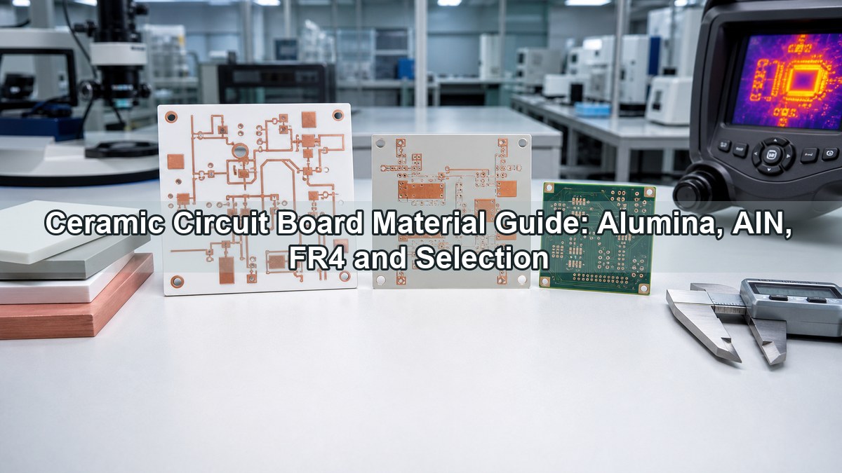
Common ceramic PCB materials include alumina, aluminum nitride, and silicon nitride. Alumina is widely used because it has good insulation, mechanical strength, and cost control. Aluminum nitride is selected when higher thermal conductivity is required. Silicon nitride is often used in demanding power modules because it offers strong mechanical toughness and good thermal shock performance.

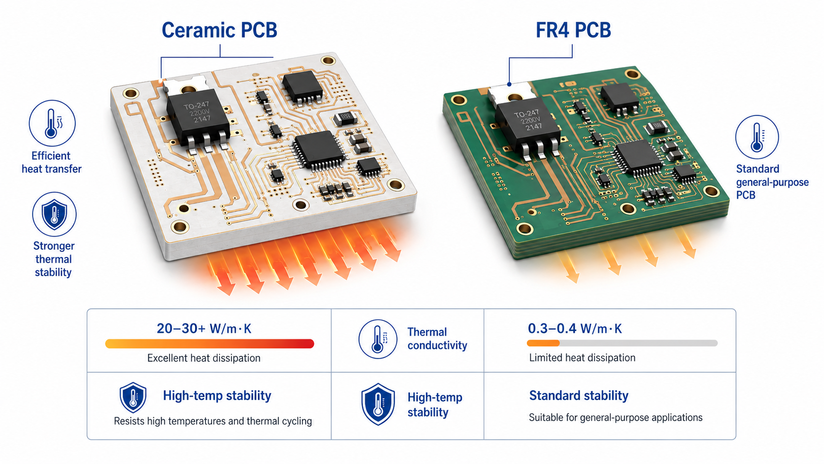
The thermal difference between FR4 and ceramic is significant. FR4 usually has thermal conductivity of about 0.3–0.4 W/m·K. Alumina ceramic is commonly around 20–30 W/m·K. Aluminum nitride can reach about 170 W/m·K or higher, depending on material grade. This helps move heat away from hot components and into a heat sink or housing.

Ceramic also provides strong dielectric performance. It can help maintain insulation in compact circuits where voltage, heat, and current are close together. This is valuable in power supplies, converters, inverters, motor drives, battery systems, high-power LEDs, medical devices, and radar communication equipment.

Engineers choose ceramic materials mainly for these reasons:

  • Better heat transfer than FR4 in power-dense designs
  • High electrical insulation for compact circuits
  • Stable performance under high operating temperatures
  • Good dimensional control during thermal cycling
  • Compatibility with thick film, thin film, DPC, DBC, AMB, LTCC, and HTCC processes

Ceramic is harder and more brittle than FR4, so design and production control are important. Edge design, hole structure, metallization adhesion, copper thickness, surface finish, and assembly stress should be reviewed early.

How Are Ceramic Printed Circuit Boards Different from FR4 PCBs?

Ceramic printed circuit boards and FR4 PCBs both connect electronic components, but they are used for different performance needs. FR4 is suitable for many general electronic products. Ceramic is used when heat transfer, insulation, temperature stability, or package reliability becomes more important.

Direct Printed Standing Ceramic Circuit Boards: What Should Engineers Know?

Ceramic PCBs are chosen when the board must work as part of the thermal and electrical structure. They are common in high-power LEDs, power modules, RF packages, automotive electronics, medical modules, and industrial control systems. Ceramic can move heat more efficiently and maintain stable insulation under higher stress conditions.

ItemFR4 PCBCeramic Printed Circuit Board
Base MaterialGlass-reinforced epoxy laminateAlumina, AlN, silicon nitride, LTCC, HTCC
Thermal ConductivityAbout 0.3–0.4 W/m·KAlumina about 20–30 W/m·K; AlN about 170 W/m·K or higher
Cost LevelLower for standard productionHigher due to material and process cost
Mechanical BehaviorTough and easy to processHard, rigid, and dimensionally stable
Heat ResistanceSuitable for general electronicsBetter for high-temperature applications
Common ApplicationsConsumer, industrial, communication, control boardsPower, LED, RF, medical, automotive, aerospace
Process FocusLamination, drilling, plating, etchingMetallization, firing, plating, bonding, ceramic shaping

FR4 should remain the first choice for many standard designs because it is efficient and economical. Ceramic becomes the better choice when a standard PCB structure cannot meet thermal, voltage, or stability requirements.

What Does “Direct Printed” Mean in Circuit Board Manufacturing?

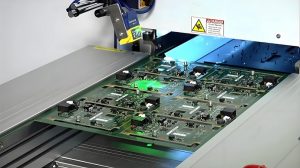
“Direct printed” means the conductive circuit pattern is formed directly on the substrate surface. In ceramic PCB manufacturing, this may involve printing conductive paste, depositing metal layers, electroplating copper, firing metallization, or using direct imaging and patterning methods.

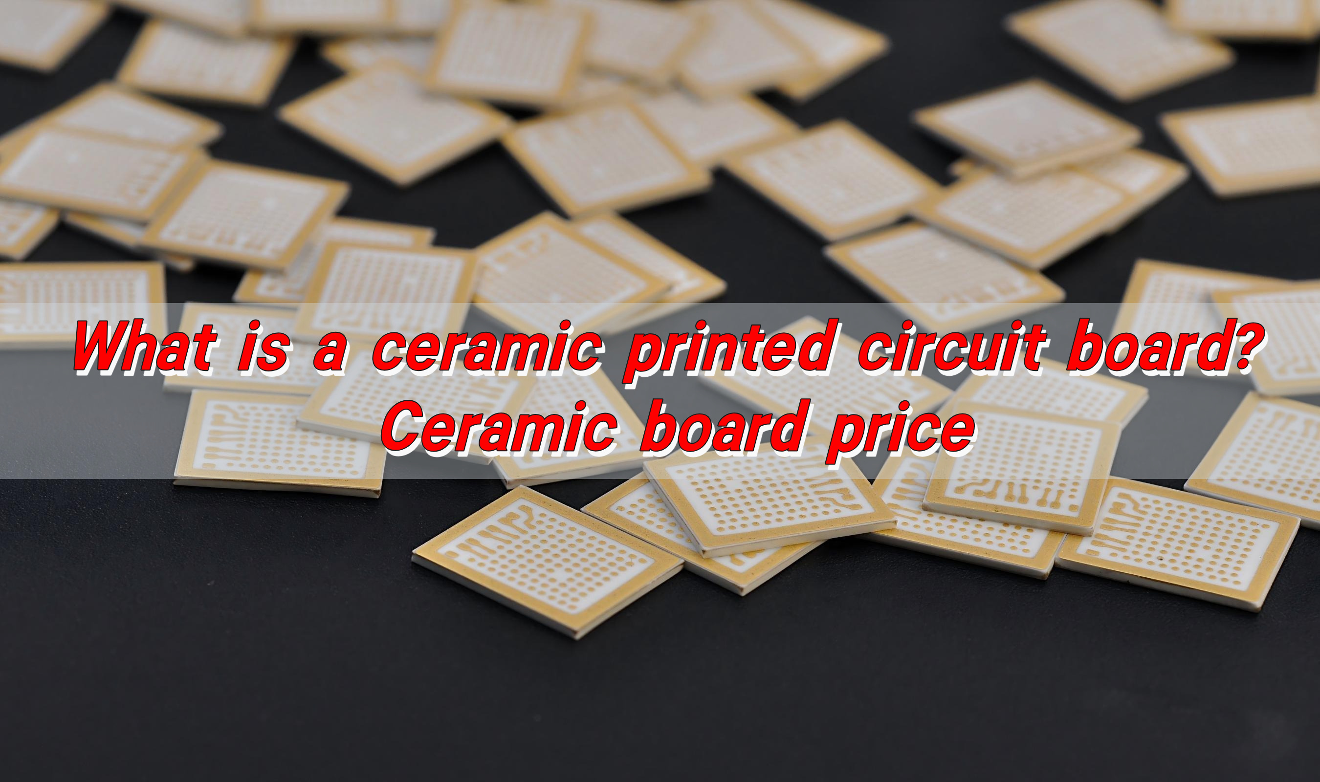
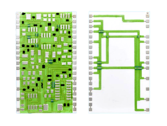
In thick-film ceramic circuits, direct printing usually refers to screen printing conductive paste onto the ceramic substrate. The printed layer is dried and fired so the conductor bonds to the ceramic surface. Conductive materials may include silver, palladium-silver, gold, platinum-gold, or other paste systems. This process is used for hybrid circuits, sensors, heaters, resistive elements, and control modules.

In DPC ceramic PCB manufacturing, the process is different. The ceramic substrate may be laser drilled, cleaned, activated, coated with a seed layer, electroplated with copper, imaged, and etched. This allows finer circuits and thicker copper than many printed paste systems.

The phrase may also appear in discussions of digital printed circuit board technology. Digital printing can refer to inkjet conductive ink, additive electronics, or direct imaging. These methods are useful in some prototypes and special applications, but they should not be confused with high-power DPC, DBC, AMB, LTCC, or HTCC ceramic PCB processes.

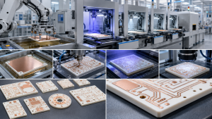
How Are Direct Printed Ceramic Circuit Boards Made?

Direct printed ceramic circuit boards are made through substrate preparation, pattern formation, metallization, thermal processing, surface finishing, shaping, inspection, and testing. The process depends on the ceramic material and circuit technology.

For thick-film ceramic circuits, production starts with a cleaned ceramic substrate. Conductive paste is screen printed onto the substrate through a patterned mesh. The printed layer is dried, then fired in a controlled furnace. Additional conductive, resistive, dielectric, or protective layers can be printed and fired if the design requires them.

Direct Printed Standing Ceramic Circuit Boards: What Should Engineers Know?

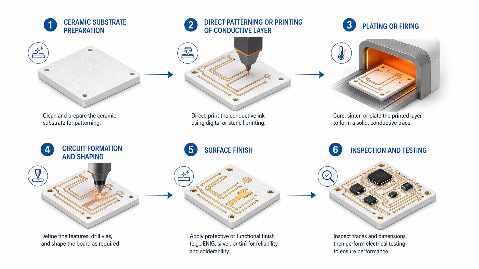
For DPC ceramic PCBs, the process often includes laser drilling, cleaning, seed layer deposition, copper electroplating, imaging, etching, surface finishing, and final inspection. DPC is suitable for fine circuits, high-power LEDs, laser modules, and compact thermal designs.

DBC and AMB ceramic boards use copper bonding processes instead of paste printing. DBC bonds copper directly to ceramic under high temperature. AMB uses an active metal brazing layer to bond copper to ceramic. These technologies are widely used in power modules where copper thickness, thermal transfer, and bonding strength are important.

A typical manufacturing flow includes:

  • DFM review of material, conductor system, line width, spacing, copper thickness, hole structure, and surface finish
  • Ceramic substrate cleaning and inspection
  • Circuit pattern formation by printing, imaging, plating, bonding, or etching
  • Firing, brazing, curing, or plating build-up according to the selected process
  • Surface finish application for soldering, wire bonding, or die attach
  • Mechanical shaping by laser cutting, scribing, CNC processing, dicing, or grinding
  • Electrical test, dimensional inspection, visual inspection, and reliability checks
  • Protective packaging for shipment and assembly

EBest Circuit supports thick-film, DPC, DBC, AMB, LTCC, and HTCC ceramic PCB technologies. This process range helps customers match the manufacturing method to the design instead of forcing one process into every application.

What Are the Benefits of Direct Printed Ceramic Circuit Boards?

Direct printed ceramic circuit boards offer strong thermal transfer, electrical insulation, dimensional stability, and process flexibility. These benefits make them suitable for compact and high-reliability electronic products.

Thermal performance is the main reason many engineers select ceramic. Power devices, LEDs, laser diodes, high-power resistors, and RF components can generate concentrated heat. Ceramic helps move heat away from these components more efficiently than FR4. This can support stable performance and a longer product life.

Main benefits include:

  • Improved heat transfer for power and LED applications
  • Strong insulation for high-voltage and compact layouts
  • Stable performance under higher operating temperatures
  • Good dimensional control during thermal cycling
  • Compatibility with several ceramic PCB technologies
  • Support for soldering, wire bonding, die attach, and hybrid assembly

The business value is also practical. A well-designed ceramic PCB can help reduce thermal risk, support compact modules, and improve product consistency. For buyers, the key is to select the correct ceramic type and process at the beginning rather than treating all ceramic PCBs as the same product.

What Applications Need Direct Printed Standing Ceramic Circuit Boards?

Direct printed standing ceramic circuit boards are used in products that need heat control, insulation, compact structure, and reliable long-term performance. They are common in power electronics, automotive electronics, medical equipment, LED systems, laser modules, industrial controls, instrumentation, RF modules, and radar communication.

Power electronics is one of the main application areas. Converters, inverters, motor drives, IGBT modules, MOSFET modules, and power supplies often require efficient heat transfer and reliable insulation. DBC and AMB ceramic substrates are often used in these products because they can support bonded copper layers and high thermal loads.

Direct Printed Standing Ceramic Circuit Boards: What Should Engineers Know?

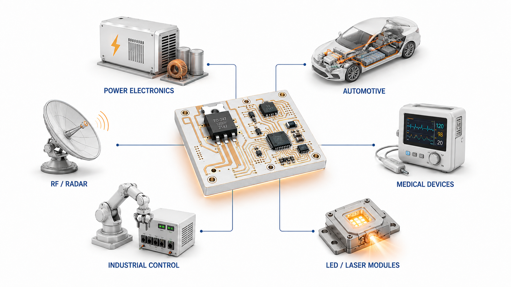
LED and laser systems also use ceramic circuit boards. High-power LEDs and laser diodes need stable heat spreading to maintain performance. DPC ceramic PCBs are common in these designs because they can support fine circuits and effective heat dissipation.

Automotive electronics often require durability under heat, vibration, and thermal cycling. Ceramic boards can be used in EV power systems, battery management, lighting modules, sensors, braking systems, and control units.

Medical equipment may use ceramic printed circuit boards in diagnostic modules, imaging equipment, surgical instruments, sensors, and precision control systems. These products often require stable performance, controlled quality, and reliable assembly.

Typical applications include:

  • Power modules for converters, inverters, motor drives, and power supplies
  • EV electronics, battery systems, automotive lighting, and braking control
  • High-power LED, UV LED, laser diode, and optical modules
  • Medical diagnostic equipment, sensors, and precision modules
  • Industrial control, instrumentation, frequency conversion, and automation systems
  • RF modules, radar communication, aerospace electronics, and defense-related equipment

For RFQ preparation, engineers should provide operating temperature, current, voltage, peak power, board size, ceramic type preference, surface finish, assembly method, expected lifetime, and test requirements. These details help the manufacturer recommend the correct process.

What Testing Is Needed for Ceramic Printed Circuit Boards?

Testing for ceramic printed circuit boards should verify electrical performance, dimensional accuracy, metallization quality, surface finish, thermal reliability, and assembly readiness. The test plan should match the board type and application.

Electrical testing checks opens, shorts, resistance, and insulation. For high-voltage products, dielectric withstand and insulation resistance tests may be required. These tests confirm that the board can maintain safe electrical separation during operation.

Visual and dimensional inspection checks cracks, chips, scratches, contamination, conductor defects, edge quality, hole position, board thickness, line width, spacing, pad size, and flatness. Ceramic boards are hard and rigid, so edge quality and handling control are important.

Metallization testing checks conductor adhesion, thickness, solderability, and surface finish quality. Adhesion is critical because the metal layer must remain stable during soldering, wire bonding, thermal cycling, and long-term use.

Thermal reliability testing may include thermal cycling, thermal shock, high-temperature storage, humidity exposure, power cycling, and aging. These tests are common in automotive, power electronics, outdoor LED, and industrial applications.

Test TypePurposeCommon Checks
Electrical TestConfirms circuit connection and isolationOpens, shorts, resistance, insulation resistance
Dimensional InspectionVerifies mechanical fitThickness, outline, holes, pads, line width, spacing
Visual InspectionChecks surface and structureCracks, chips, scratches, contamination, pattern defects
Metallization TestConfirms conductor qualityThickness, adhesion, solderability, plating quality
Surface Finish TestVerifies assembly readinessENIG thickness, oxidation, solderability, bondability
Thermal Reliability TestChecks performance under heat stressThermal cycling, thermal shock, power cycling
Assembly InspectionConfirms soldering or bonding qualityAOI, X-ray, shear test, wire bond pull test

For ceramic PCBA, additional tests may include AOI, X-ray inspection, ICT, functional testing, thermal aging, and load testing. X-ray inspection is useful for large thermal pads, power components, and solder joints where void control affects heat transfer.

Acceptance criteria should be defined before production. Useful criteria include conductor thickness, surface finish thickness, insulation resistance, solderability requirement, warpage limit, cosmetic standard, and reliability test conditions. Clear criteria help suppliers control production and help customers evaluate the delivered boards.

Direct printed standing ceramic circuit boards are suitable for designs that need efficient heat transfer, strong insulation, stable dimensions, and reliable operation in demanding environments. Engineers should confirm the ceramic material, conductor system, manufacturing process, surface finish, operating conditions, and test plan before production. For ceramic PCB design, prototype, manufacturing, or assembly support, contact EBest Circuit at sales@bestpcbs.com

You may also like

Ceramic Circuit Board: What Should You Know Before Choosing One?
Monday, May 25th, 2026

What Is a Ceramic Circuit Board?

A ceramic circuit board is a printed circuit board that uses ceramic material as the insulating substrate instead of standard FR4 laminate. It supports copper circuits, carries electronic components, and helps manage heat in applications where ordinary PCB materials may not provide enough thermal or electrical performance.

Ceramic Circuit Board: What Should You Know Before Choosing One?

Common ceramic circuit board materials include alumina, aluminum nitride, and silicon nitride. Each material has its own performance profile. Alumina is widely used because it offers a balanced combination of insulation, mechanical strength, thermal performance, and cost control. Aluminum nitride provides much higher thermal conductivity, making it suitable for high-power modules and compact thermal designs. Silicon nitride is often selected when mechanical toughness and thermal shock resistance are important.

A ceramic printed circuit board is often used in products that require excellent heat dissipation, high insulation strength, stable dimensions, and long service life. Typical applications include LED modules, power electronics, automotive electronics, medical devices, RF modules, laser equipment, industrial control systems, and aerospace electronics.

Compared with standard FR4, ceramic is not selected only for appearance or premium positioning. It is chosen because the material can support more demanding electrical and thermal conditions. In high-power circuits, heat can build up around components quickly. A ceramic pcb substrate helps move that heat away from the source more effectively, improving the operating stability of the final product.

For buyers and engineers, choosing a ceramic circuit board should start with the application requirements. Important factors include working temperature, power density, voltage level, copper thickness, circuit precision, assembly method, and production volume. EBest Circuit (Best Technology) supports ceramic PCB fabrication with material guidance, DFM review, process control, testing, and assembly support, helping customers move from prototype verification to production with fewer design risks.

How Does a Ceramic Circuit Board Work?

A ceramic circuit board works by combining an electrically insulating ceramic substrate with conductive copper circuits. The ceramic base provides mechanical support and insulation. The copper layer forms the electrical path for current and signals. When components generate heat, the ceramic substrate helps transfer that heat away from the component area and toward a heatsink, housing, or cooling structure.

This working principle is important in high-power electronics. For example, in an LED module, heat is generated near the LED chip. If the heat is not removed efficiently, brightness, color stability, and service life may be affected. A ceramic circuit board improves thermal transfer because ceramic materials conduct heat much better than standard FR4. This helps keep the operating temperature more stable.

The copper layer also plays a key role. It carries electrical current, spreads heat, and connects components. Depending on the board type, copper may be plated, bonded, printed, or brazed onto the ceramic surface. The bond between copper and ceramic must be strong enough to withstand soldering temperature, thermal expansion, electrical load, and repeated operating cycles.

Ceramic Circuit Board: What Should You Know Before Choosing One?

A ceramic printed circuit board usually works through three functional parts:

  • Ceramic substrate: provides insulation, thermal transfer, and structural support.
  • Copper circuit layer: carries current, signals, and heat across the board.
  • Assembly layer: connects LEDs, chips, resistors, capacitors, sensors, connectors, or power devices.

The final performance depends on both material and design. Ceramic material gives the board strong thermal potential, but copper layout, substrate thickness, solder pad design, surface finish, and mounting method also affect the result. A ceramic board used in a power module, for example, needs a clear thermal path from the heat source to the cooling surface. A board used in RF equipment may need stable dimensions, tight tolerance, and controlled circuit geometry.

How Is a Ceramic Circuit Board Different from an FR4 PCB?

A ceramic circuit board and an FR4 PCB both provide electrical interconnection, but their base materials behave very differently. FR4 is made from glass fiber reinforced epoxy resin. It is widely used because it is cost-effective, easy to process, and suitable for many electronic products. Ceramic boards use inorganic ceramic substrates, which provide higher thermal conductivity, stronger insulation stability, and better dimensional control under heat.

The most important difference is thermal conductivity. Standard FR4 usually has thermal conductivity of about 0.3 W/m·K. Alumina ceramic is commonly around 20–30 W/m·K, while aluminum nitride can reach about 140–180 W/m·K, depending on material grade and production process.

FR4 remains a practical choice for many control boards, communication boards, consumer electronics, and general industrial products. Ceramic becomes more suitable when heat dissipation, high-voltage insulation, compact structure, or long-term reliability becomes a key design requirement.

Comparison ItemCeramic Circuit BoardFR4 PCB
Base MaterialAlumina, aluminum nitride, silicon nitride, or other ceramic materialGlass fiber reinforced epoxy laminate
Thermal ConductivityAbout 20–180 W/m·K depending on materialAbout 0.3 W/m·K
Electrical InsulationExcellent for high-voltage and high-power circuitsGood for standard electronic circuits
Heat ResistanceStrong performance in high-temperature applicationsSuitable for normal PCB operating ranges
Dimensional StabilityVery stable under temperature changesMore affected by heat and moisture
Mechanical BehaviorHard, stable, and brittle during processingEasier to drill, route, and laminate
Cost LevelHigher material and process costMore economical for general use
Typical ApplicationsLEDs, power modules, RF devices, medical, automotive, aerospaceControl boards, consumer electronics, communication modules, general PCBA

The right choice depends on the product environment. FR4 is suitable when the design has moderate power and enough space for thermal management. Ceramic is more suitable when the board itself must help handle heat, voltage, stability, or compact packaging. Cost should be reviewed together with the total product design. In some cases, ceramic can reduce the need for larger heatsinks or additional thermal structures.

Ceramic PCB vs FR4: Which One Should You Choose?

The choice between ceramic PCB and FR4 depends on power level, heat load, voltage requirement, product size, reliability target, and budget. FR4 is usually the preferred option for standard circuits because it offers good electrical performance, mature manufacturing, and lower cost. Ceramic circuit boards are better suited for applications that require stronger heat transfer, higher insulation strength, and stable operation under demanding conditions.

Ceramic Circuit Board: What Should You Know Before Choosing One?

If the product is a low-power control board, sensor interface board, or general communication module, FR4 may be sufficient. If the product uses high-power LEDs, MOSFETs, IGBTs, laser diodes, RF power components, or compact power modules, ceramic should be evaluated early in the design stage.

Selection QuestionBetter Fit
Is the design low power and cost-sensitive?FR4 PCB
Does the board need strong heat dissipation?Ceramic circuit board
Are high-power LEDs or power semiconductors used?Ceramic circuit board
Is the circuit mainly digital control or low-power signal processing?FR4 PCB
Is high-voltage insulation a major requirement?Ceramic circuit board
Is fast and economical multilayer production the main goal?FR4 PCB
Does the product need compact size with better thermal transfer?Ceramic circuit board
Is the application used in automotive, medical, aerospace, or industrial power systems?Often ceramic, depending on design requirements

A practical material selection process should include thermal analysis, dielectric strength review, copper thickness selection, soldering method, mechanical mounting, and assembly requirements. Ceramic can provide strong performance, but it should match the actual design need. Over-specifying material may increase cost without adding meaningful value.

EBest Circuit (Best Technology) can review Gerber files, stackup information, power data, and application requirements to help determine whether ceramic, FR4, metal core PCB, or a hybrid structure is more suitable.

Why Are Ceramic Materials Used for Circuit Boards?

Ceramic materials are used for circuit boards because they combine electrical insulation, thermal conductivity, dimensional stability, and high-temperature resistance. This combination is valuable in electronic products that need to carry current while controlling heat.

In many circuits, the substrate must insulate copper traces and components from each other. At the same time, it may need to move heat away from active devices. Ceramic materials can perform both functions well. They are electrically insulating but thermally conductive, which makes them suitable for high-power and high-reliability applications.

The most common ceramic circuit board materials include alumina, aluminum nitride, and silicon nitride. Alumina is often used for LED modules, sensors, industrial electronics, and general ceramic PCB applications. Aluminum nitride is selected when thermal performance is the main concern. Silicon nitride is useful when the design needs higher mechanical strength and resistance to thermal shock.

Ceramic materials also have good chemical stability. They resist moisture, oxidation, and many harsh environments better than organic materials. Their low coefficient of thermal expansion helps reduce dimensional changes during heating and cooling. This is important for products exposed to repeated thermal cycles.

Main reasons ceramic materials are used include:

  • Better heat transfer for power components, LEDs, and compact modules.
  • Strong electrical insulation for high-voltage and high-density circuits.
  • High temperature capability for demanding operating environments.
  • Stable dimensions during thermal cycling and assembly.
  • Long-term reliability for industrial, automotive, medical, and aerospace applications.

Material selection should be based on real working conditions. Alumina is a balanced option for many projects. Aluminum nitride is preferred when heat dissipation is critical. Silicon nitride is considered when strength and thermal shock performance are priorities. A ceramic pcb manufacturer should help match the material to the application instead of recommending one substrate for every project.

What Are the Main Benefits of Ceramic Circuit Boards?

The main benefits of ceramic circuit boards are stronger thermal performance, excellent insulation, stable structure, and reliable operation in demanding environments. These benefits make ceramic suitable for products where heat, power density, and service life are important.

The most recognized benefit is heat dissipation. Heat affects component performance and product reliability. A ceramic pcb substrate provides a more efficient thermal path than FR4, helping components operate within a safer temperature range. This is useful for LEDs, power semiconductors, laser modules, and high-current circuits.

Ceramic circuit boards also provide excellent electrical insulation. This is important in power supplies, inverters, battery systems, medical devices, and high-voltage electronics. The material helps separate conductive layers and supports stable operation where insulation strength is a key requirement.

Another benefit is dimensional stability. Ceramic materials expand less than many organic PCB materials when temperature changes. This helps maintain circuit accuracy, component alignment, and solder joint stability. In precision electronics, RF devices, and high-reliability modules, this stability can improve consistency.

BenefitPractical Value
High Thermal ConductivityHelps remove heat from components more efficiently
Excellent Electrical InsulationSupports high-voltage and high-power circuits
Strong Dimensional StabilityHelps maintain circuit accuracy under temperature changes
High Temperature ResistanceSuitable for heat-intensive applications
Compact Design SupportHelps reduce dependence on large thermal structures in some designs
Good Chemical StabilitySupports use in demanding environments
Long-Term ReliabilitySuitable for products with extended operating life

Ceramic circuit boards are especially valuable when multiple requirements appear together. A board may need to handle high power, remain compact, provide insulation, and operate for many years. In these cases, ceramic can offer a strong technical foundation.

EBest Circuit (Best Technology) supports customers with ceramic PCB fabrication, PCB assembly, DFM review, material selection, testing, and production-quality support. This helps engineers select the right ceramic circuit board material and avoid issues related to copper adhesion, thermal bottlenecks, tolerance control, or assembly mismatch.

How Does a Ceramic Circuit Board Help with Heat Dissipation?

A ceramic circuit board helps with heat dissipation by transferring heat from components through the substrate and toward the cooling structure. In many electronic products, heat begins at the component junction, passes through the package, moves through the solder joint, enters the copper layer, and then travels into the board. If the substrate has poor thermal conductivity, heat may remain close to the component. Ceramic improves this path because it conducts heat much more effectively than standard FR4.

This advantage is important for high-power LEDs, power modules, RF power devices, laser diodes, and compact energy systems. These products often generate concentrated heat in small areas. A ceramic substrate helps spread and conduct that heat, reducing thermal stress around critical components.

The level of heat dissipation depends on the ceramic material. Alumina provides solid thermal performance for many applications. Aluminum nitride offers much higher thermal conductivity and is used when thermal control is a top priority. Copper thickness, copper area, substrate thickness, solder pad design, and mounting method also affect the final result.

MaterialTypical Thermal ConductivityCommon Use
Standard FR4About 0.3 W/m·KGeneral PCB circuits
Alumina CeramicAbout 20–30 W/m·KLEDs, sensors, industrial electronics, power modules
Aluminum Nitride CeramicAbout 140–180 W/m·KHigh-power modules, laser devices, compact thermal designs
CopperAbout 385 W/m·KCircuit traces, heat spreading, power paths

Thermal design should consider the full heat path. The board material is only one part of the system. Component placement, copper layout, thermal pads, solder quality, thermal interface material, heatsink contact, and housing design all influence temperature control.

For example, a high-power LED module may use a ceramic substrate with a large copper pad under the LED. Heat moves from the LED package into the copper, through the ceramic, and then into the heatsink. If the design uses aluminum nitride, the heat transfer can be stronger, which helps compact lighting products and high-output modules.

How Are Ceramic Circuit Boards Manufactured?

Ceramic circuit boards can be manufactured through several processes, including DPC, DBC, AMB, thick film, and thin film technology. The right process depends on copper thickness, circuit precision, thermal demand, bonding strength, production volume, and application type.

Ceramic Circuit Board: What Should You Know Before Choosing One?

DPC, or Direct Plated Copper, is often used for fine circuits and compact ceramic PCB designs. Copper is deposited onto the ceramic substrate through metallization and plating. This process supports good pattern accuracy, smooth surface quality, and smaller circuit features. DPC is common in LED modules, sensors, RF devices, and precision electronic modules.

DBC, or Direct Bonded Copper, bonds copper foil directly to ceramic under high temperature. It supports thicker copper and higher current capacity. DBC ceramic printed circuit boards are widely used in power electronics, motor drives, inverters, automotive power systems, and industrial control equipment.

AMB, or Active Metal Brazing, uses active brazing material to bond copper and ceramic. It provides strong bonding strength and good thermal cycling performance. AMB is often selected for demanding power modules and high-reliability applications.

Thick film ceramic boards are made by printing conductive paste onto the ceramic surface and firing it at high temperature. This process is used for hybrid circuits, sensors, resistive circuits, and custom electronic modules. Thin film ceramic boards are used for high-precision circuits, RF designs, microwave products, and applications requiring stable electrical characteristics.

ProcessMain FeatureSuitable Applications
DPC Ceramic PCBFine circuits and plated copperLEDs, sensors, RF modules, compact electronics
DBC Ceramic PCBThick copper and high current capacityPower modules, inverters, automotive electronics
AMB Ceramic PCBStrong copper-to-ceramic bondingHigh-reliability power electronics
Thick Film Ceramic PCBPrinted conductive paste and fired circuitsHybrid circuits, sensors, custom modules
Thin Film Ceramic PCBHigh precision and stable electrical behaviorRF, microwave, precision circuits

The manufacturing flow usually includes material selection, substrate preparation, cleaning, metallization, copper forming, imaging, etching, surface finishing, inspection, and testing. If the project includes assembly, SMT, chip bonding, wire bonding, or module assembly may follow.

Ceramic is harder and more brittle than FR4, so processing control is important. Cutting, drilling, laser processing, copper adhesion, surface finish, tolerance, and inspection must be managed carefully. A capable ceramic pcb manufacturer should understand both the material and the final product requirements.

EBest Circuit (Best Technology) provides ceramic PCB fabrication and PCBA support with DFM review, process evaluation, electrical testing, and production control. This helps customers reduce manufacturing risk and improve consistency from sample builds to volume production.

What Applications Use Ceramic Circuit Boards?

Ceramic circuit boards are used in applications that require reliable heat dissipation, high insulation strength, compact structure, and stable long-term performance. They are common in industries where the PCB must do more than provide basic electrical connection.

Common applications include:

  • High-power LED modules and lighting systems
  • Power semiconductor modules
  • Automotive lighting and electronic control units
  • Battery management and energy conversion systems
  • RF, microwave, and radar electronics
  • Medical sensors and diagnostic modules
  • Industrial control and automation equipment
  • Laser modules and optical electronics
  • Aerospace and high-reliability electronic systems

A ceramic circuit board is a strong choice when the product needs better heat dissipation, excellent insulation, stable dimensions, and dependable long-term performance. FR4 remains suitable for many standard PCB projects, while ceramic provides a higher-performance option for thermal, power, RF, medical, automotive, and industrial applications. Before choosing one, review the ceramic circuit board material, manufacturing process, copper thickness, thermal path, voltage requirement, tolerance, and assembly method together.

For ceramic printed circuit boards, PCB fabrication, PCBA assembly, and engineering support, EBest Circuit (Best Technology) can help evaluate your design and production needs. For project consultation or quotation, contact sales@bestpcbs.com

You may also like

What Is a Ceramic Printed Circuit Board? Ceramic Board Price
Friday, November 14th, 2025

Ceramic printed circuit board is a PCB made with a ceramic base instead of resin. Its main strength is fast heat transfer, which keeps components cooler and more stable. Because ceramic handles high power and tough environments well, it’s used in LEDs, automotive systems, medical devices, and high-frequency electronics.

What Is a Ceramic Printed Circuit Board? Ceramic Board Price

What Is a Ceramic PCB?

Ceramic printed circuit board is a board made from ceramic materials instead of traditional resin-based laminates. Ceramic materials have a natural ability to handle heat. They move heat away from components fast, which protects sensitive parts during operation.

This type of board uses ceramic as the base. Common ceramic materials include alumina, aluminum nitride, and beryllium oxide. Each type has its own strengths. All of them offer stable performance, steady conductivity, and strong durability.

Ceramic PCBs are built for harsh work. They stay stable even when temperatures climb high. This makes them a top choice for applications that demand reliability.

Ceramic printed circuit boards also carry strong mechanical strength. They resist stress and remain stable when exposed to vibration.

Are Ceramic PCBs Expensive?

Ceramic PCBs have extremely high performance. Because of this, many people assume they cost more. Ceramic board price can be higher than common materials. But this cost comes with advantages that help reduce risks in the long run.

Ceramic boards help lower failure rates. They also support higher power levels. They reduce heat-related damage.

Many ceramic printed circuit board manufacturers now offer cost-effective options. Improved production methods have made ceramic PCBs more accessible. As technology grows, the price gap continues to shrink.

So yes, ceramic PCBs can be more expensive, but the value is strong. They bring stable and safe performance that protects the final product.

What Affects Ceramic Board Price?

Ceramic board price depends on several factors. Each factor influences the final cost.

  • 1. Material Type

Different ceramic materials have different costs. Aluminum nitride, for example, offers very high thermal conductivity. Because of this, it often costs more. Alumina is more affordable and works well for many applications.

  • 2. Board Thickness

Thicker boards use more material. This increases the price.

  • 3. Layer Count

A single-layer ceramic PCB costs less than a multilayer design. Multilayer boards need extra processes and bonding methods. This adds complexity and raises cost.

  • 4. Conductive Layer

Ceramic PCBs use thick-film or thin-film metallization. Each method has its own cost. Silver, gold, and copper can also influence the total price.

  • 5. Manufacturing Technology

Ceramic PCBs require special equipment. Some boards need laser cutting. Some need advanced firing ovens.

  • 6. Design Complexity

A simple design is cheaper. A design with dense pads, small traces, and tight spacing costs more.

  • 7. Order Quantity

Large orders usually cost less per unit. Smaller orders can be more expensive.

  • 8. Surface Treatment

Extra surface finishes add cost. Gold plating or special coatings improve durability and performance, but they also increase the price.

  • 9. Testing Requirements

Some industries need strict tests. These tests help ensure quality. Extra testing adds cost but provides more assurance.

What Is a Ceramic Printed Circuit Board? Ceramic Board Price

Even with these factors, ceramic board price has become more competitive. Many ceramic printed circuit board factories offer flexible options to fit different budgets.

What Are the Types of Ceramic Circuit Board?

Ceramic circuit boards come in several types. Each one supports different needs.

  • Thick-Film Ceramic PCB: Conductive paste is printed onto the ceramic surface. It offers stable performance at a reasonable cost.
  • Thin-Film Ceramic PCB: Thin-film boards offer high precision. They use vacuum deposition to create fine lines.
  • DBC (Direct Bonded Copper) Ceramic PCB: In this type, copper is bonded directly to the ceramic. It offers incredible thermal performance.
  • Hybrid Ceramic PCB: This type combines ceramic and other materials. It improves performance while keeping cost flexible.

Each type has its own unique benefits. The specific choice depends on your application and design requirements.

How Does a Ceramic Printed Circuit Board Work?

Ceramic printed circuit boards work by carrying signals and power across conductive layers on a ceramic base. The ceramic material holds the circuit firmly and keeps heat under control.

Heat moves through ceramic at a fast rate. This keeps components cool. The stable base also prevents bending, which helps protect tiny circuit paths.

The conductive layer, whether thick-film or thin-film, passes signals without losing accuracy. Ceramic material supports smooth transmission.

When power increases, ceramic handles the stress. Its high thermal conductivity spreads heat quickly. This helps maintain stable performance even under heavy load.

Because of this balance of temperature management and strong reliability, ceramic printed circuit boards support long-term use without problems.

Why Use a Ceramic Base Print Circuit Board?

Ceramic base print circuit board brings solid benefits. They were chosen because of their good stability, good heat dissipation, and long service life.

Ceramic boards protect components from heat. They keep signals clean. They support high-power loads without losing accuracy. Because they resist chemicals and moisture, they also stay strong in demanding environments.

What Are the Advantages of Ceramic Printed Circuit Boards?

Ceramic PCBs offer numerous advantages because they provide reliable and robust performance.

  • 1. Excellent Thermal Conductivity

Ceramic moves heat fast. This helps cool components. It also reduces heat-related problems.

  • 2. High Mechanical Strength

Ceramic materials resist stress. They do not deform easily. This helps protect the circuit.

  • 3. Stable in Harsh Environments

Ceramic stays strong even when temperatures rise. It also resists chemicals and moisture.

  • 4. Long Lifespan

Ceramic PCBs last a long time. They support heavy-duty work without breaking down.

  • 5. Low Dielectric Loss

This feature helps improve signal quality. Many RF devices rely on this benefit.

  • 6. Strong Reliability

Ceramic printed circuit boards offer stable and predictable performance. They help reduce unexpected issues.

  • 7. Compact Design Possibility

They support high-density layouts. This helps shrink overall product size.

What Is a Ceramic Printed Circuit Board? Ceramic Board Price

What Is the Difference Between Ceramic PCB and FR4?

Ceramic and FR4 have different qualities. Each one serves a specific purpose.

  • 1. Thermal Performance

Ceramic handles heat much better. FR4 cannot match ceramic in this area. Devices that generate strong heat prefer ceramic.

  • 2. Mechanical Strength

Ceramic has stronger stability. FR4 is easier to bend. Ceramic protects the circuit better in tough environments.

  • 3. Electrical Properties

Ceramic has better dielectric performance. It helps support high-frequency signals with lower loss.

  • 4. Cost

FR4 is cheaper. Ceramic costs more but offers better performance.

  • 5. Application Field

FR4 works well for common devices. Ceramic is used for high-end, high-power, and high-temperature applications.

Where Are Ceramic Printed Circuit Boards Used?

Ceramic printed circuit boards are used in many advanced applications. Their strength and heat-handling ability make them ideal for demanding work.

  • LED Lighting Systems: High-power LEDs use ceramic boards to stay cool. This helps extend LED lifespan.
  • Automotive Electronics: Ceramic PCBs support engine control units, sensors, and power modules. They can handle vibration and heat.
  • Medical Devices: Medical tools need stable circuits. Ceramic PCBs support imaging equipment and diagnostic devices.
  • Aerospace Systems: Ceramic offers strong reliability. Aircraft and satellites depend on stable performance in extreme conditions.
  • Power Electronics: Devices that handle high power depend on ceramic. The material helps reduce heat and improve safety.
  • Communication Devices: High-frequency modules use ceramic because of its low dielectric loss.
  • Industrial Control: Robotic systems and automation equipment rely on ceramic PCBs for safe performance.

These industries trust ceramic because it delivers powerful and dependable results.

What Materials Do Ceramic Printed Circuit Board Manufacturers Use?

Ceramic printed circuit board manufacturers use several popular materials. Each one supports different needs.

  • 1. Alumina (Al₂O₃)

This is the most common ceramic material. It offers balanced cost and performance.

  • 2. Aluminum Nitride (AlN)

This material has high thermal conductivity. It handles heat extremely well. It is ideal for high-power devices.

  • 3. Beryllium Oxide (BeO)

BeO offers excellent heat performance. It is used less often because of handling restrictions. Some high-end applications still use it.

  • 4. Zirconia

Zirconia offers high strength. It is used for certain structural needs.

BEST Technology will select materials based on your requirements. We will consider heat resistance, strength, cost, and performance. This ensures the final product meets your expectations.

How to Manufacture Ceramic Printed Circuit Board?

Ceramic PCB manufacturing involves several steps. Each step ensures quality and stability.

  • Material Preparation: Ceramic sheets are prepared in controlled environments. They must be clean and smooth.
  • Metallization: Conductive layers are added. This can be done through thick-film or thin-film processes. The metallization forms the circuit traces.
  • Printing: For thick-film boards, conductive paste is printed onto the ceramic surface. Precision is important.
  • Firing: The board is placed in a high-temperature oven. This step sinters the material and bonds the traces securely.
  • Laser Machining: Some designs need small holes or fine cuts. Lasers provide accurate shaping.
  • Plating and Surface Finish: Surface finishes improve reliability. They also protect the surface.
  • Testing: Each board is tested to ensure proper performance.
  • Final Inspection: We will inspect the circuit boards, including alignment, trace quality, and strength.

Conclusion:

Ceramic printed circuit board offers powerful performance, fast heat transfer, strong mechanical durability, and stable electrical properties. It supports high-power systems, advanced sensors, medical devices, LED technology, and automotive electronics. While ceramic board price can be higher than standard boards, the value is strong.

If you need high-quality ceramic printed circuit boards or want a quote, feel free to contact: sales@bestpcbs.com

You may also like