PCB manufacturing PCB manufacturing
Home > Blog

Reliable SMT PCBA Process for Turnkey Medical Projects

January 26th, 2026

The SMT PCBA process​ is the backbone of modern electronics manufacturing, involving the automated placement and soldering of components onto printed circuit boards. This article provides a comprehensive guide to building a stable SMT production line, with a special focus on the critical engineering controls needed for turnkey medical device projects.

Launching a medical device often stalls not at design, but at manufacturing—where compliance, reliability, and execution risks quickly compound.

  • Lack of true medical compliance expertise beyond basic PCB assembly (ISO 13485, FDA QSR).
  • Unstable sourcing for long-lifecycle medical components and obsolescence risk.
  • Yield loss and inconsistency when assembling fine-pitch and miniature components.
  • Heavy documentation and validation burdens for regulatory submissions.
  • Fragmented communication in turnkey projects without clear ownership.

These challenges are addressed by partnering with a medical-focused EMS provider built around process control, traceability, and regulatory readiness.

  • ISO 13485–certified quality system with audit-ready workflows and DHF support.
  • Proactive component lifecycle management through dedicated medical sourcing teams.
  • Precision SMT lines validated for micro-assembly, supported by AOI and AXI.
  • Complete IQ/OQ/PQ, PFMEA, and CPK deliverables included as standard.
  • Dedicated project engineers providing end-to-end ownership from PCBA to box-build.

At EBest Circuit (Best Technology), we are a specialized provider of turnkey PCBA manufacturing services for the medical industry. Our core strength lies in a deeply engineered SMT PCBA process​ built on precision equipment, statistically controlled workflows, and a quality-first culture. Our SMT production capability is defined by advanced pick-and-place platforms, tightly controlled process flows, and rigorously validated engineering parameters—ensuring every assembly stage meets the stability and repeatability required for medical-grade manufacturing. For a consultation on your next project, contact our team at sales@bestpcbs.com.
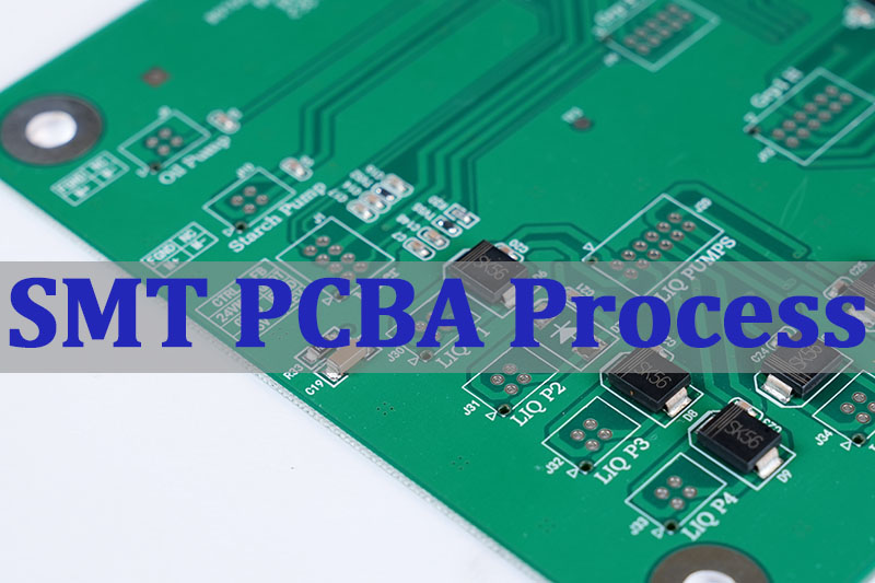
SMT PCBA Process

What Is The SMT PCBA Process?

The SMT PCBA process​ refers to the sequence of operations used to populate a bare PCB with electronic components using Surface Mount Technology (SMT). It is the dominant method for high-density, high-volume electronics assembly, including critical medical devices. This process involves applying solder paste, precisely placing components, and using controlled heat to form permanent solder joints. A well-controlled SMT process flow​ is characterized by repeatability, high yield, and the ability to handle increasingly miniaturized components. For a reliable turnkey medical project, understanding and controlling this process is non-negotiable.

The SMT assembly sequence is commonly broken into three major phases:

  • Pre-Assembly:​ This includes all preparatory steps: solder paste printing (stencil application), adhesive dispensing (if needed for mixed-technology boards), and the critical setup and programming of the SMT pick and place machine.
  • Assembly:​ The core phase where components are placed onto the pasted PCB. This stage is defined by the speed and accuracy of the automated placement equipment.
  • Post-Assembly:​ This encompasses the soldering process (typically reflow soldering), cleaning (for no-clean or water-soluble pastes), and a series of inspections (Automated Optical Inspection – AOI, X-ray Inspection – AXI) to verify quality before any PCBA plug-in assembly​ of through-hole parts.

In summary, the SMT PCBA process​ is a sophisticated, phased manufacturing methodology that transforms a bare board into a functional assembly. Its effectiveness directly determines the performance, reliability, and longevity of the final electronic product, especially in life-critical medical applications.
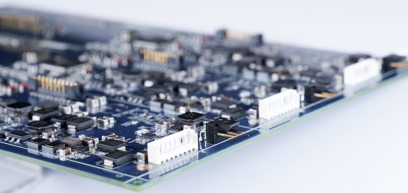
SMT PCBA Process

SMT PCBA Process Step By Step Explained

A reliable SMT assembly​ follows a defined sequence where each step builds upon the quality of the previous one. For medical projects, consistency at every stage is paramount. Here is a detailed breakdown of a standard SMT PCBA process step by step:

  • Solder Paste Printing:​ A stainless steel stencil is aligned over the PCB, and solder paste is deposited onto the solder pads. The quality of this print, including volume, alignment, and definition, is the first critical determinant of soldering success.
  • Solder Paste Inspection (SPI):​ An inline 3D SPI system measures the height, volume, and area of each solder paste deposit. This real-time feedback allows for immediate correction of printing defects, preventing a cascade of failures later.
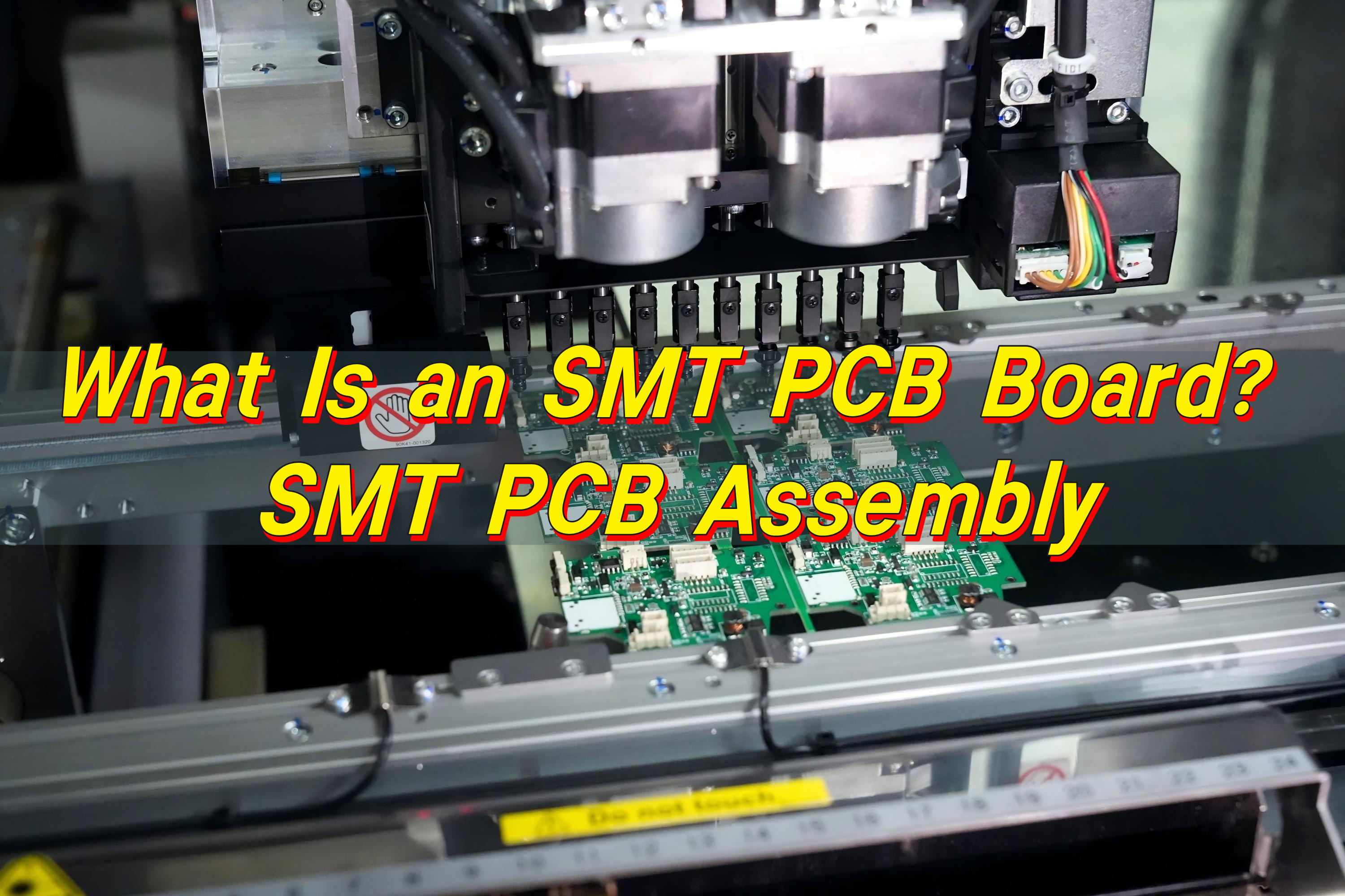
  • Component Placement:​ The PCB moves to the SMT pick and place machine. Components from reels, trays, or tubes are picked up, optically centered, and placed with micron-level accuracy onto their corresponding solder paste deposits.
  • Reflow Soldering:​ The populated board travels through a multi-zone reflow oven on a conveyor. A precise thermal profile melts the solder paste, forms intermetallic bonds, and then cools to create solid, reliable electrical and mechanical connections.
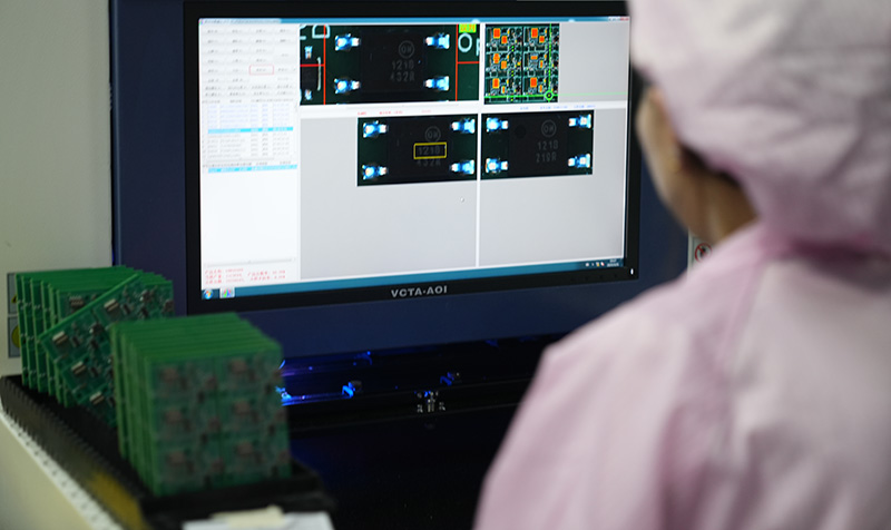
  • Automated Optical Inspection (AOI):​ Post-reflow, an AOI system uses high-resolution cameras to check for placement errors, missing components, polarity issues, and visible solder joint defects.
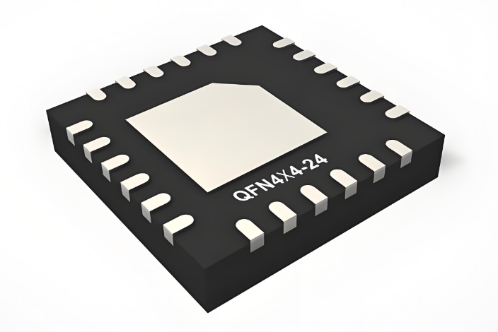
  • X-Ray Inspection (AXI):​ For medical assemblies with hidden solder joints (e.g., under BGAs or QFNs), AXI is essential. It verifies internal solder ball integrity, voiding percentage, and alignment, which are critical for long-term reliability.
  • Conformal Coating & Final Assembly:​ For medical devices requiring protection from moisture and contaminants, a conformal coating may be applied. Finally, any necessary PCBA plug-in assembly​ of through-hole components is completed.

This step-by-step SMT PCBA process flow, when executed with precision equipment and strict controls, forms the foundation of a manufacturing line capable of producing medical-grade electronics with the required traceability and zero-defect mindset.

How Does The SMT Automation Process Work?

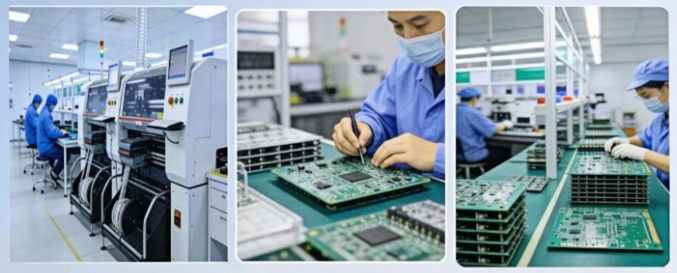
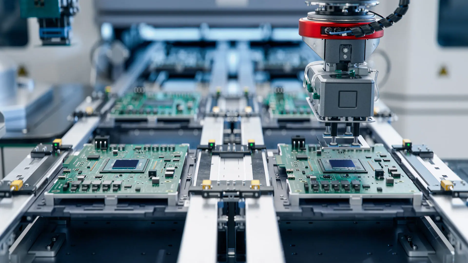
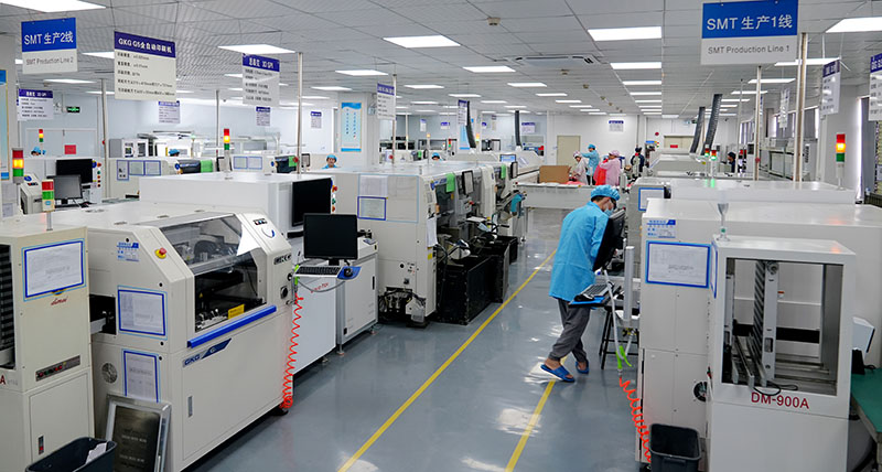
SMT automation is the backbone of modern medical PCBA manufacturing, enabling the speed, placement accuracy, and process repeatability required for regulated devices. Rather than isolated machines, automation links equipment, software, and data into a synchronized production system that minimizes variability and maximizes control.

At the core of this system is the SMT pick and place platform, supported by automated material handling, closed-loop process control, and centralized data management. Together, these elements form a fully integrated SMT production line designed for consistency, traceability, and validation readiness.

Key Elements of SMT Automation

  • Material Handling
    Automated loaders and unloaders feed bare boards into the line and remove completed assemblies, enabling continuous, stable operation with minimal manual intervention.
  • Pick and Place Operations
    High-speed and high-precision placement heads handle components ranging from 0201 passives to fine-pitch BGAs, using advanced vision systems for fiducial alignment and placement correction.
  • Process Linking
    Conveyor systems synchronize printers, SPI, placement machines, reflow ovens, and inspection stations into a single, balanced production flow.
  • Data Integration
    A Manufacturing Execution System (MES) tracks each PCB in real time, associating it with feeder setup, stencil ID, reflow profile, and inspection results to form a complete digital record.

Key Automation Technologies in an SMT Line

TechnologyPrimary FunctionMedical Manufacturing Impact
3D SPIPaste volume verificationEarly defect prevention
High-Precision PlacersAccurate micro-component placementSupports miniaturized designs
Closed-Loop ReflowStable thermal controlConsistent solder reliability
AOI / AXIAutomated defect detectionObjective quality evidence

In practice, SMT automation works as a closed-loop, data-driven environment. Inspection results feed back into placement and printing parameters, while MES data enables statistical process control and full traceability. This structure reduces human variability, stabilizes yield, and generates the documentation foundation required for SMT process validation and regulatory compliance in medical device manufacturing.

What Engineering Controls Ensure A Stable SMT Production Line?

For medical SMT PCBA processing, stability is synonymous with safety. Engineering controls are the documented procedures, specifications, and monitoring systems that prevent process drift and ensure every unit meets specification. A stable line is not achieved by chance but through deliberate, scientific control.

  • Standardized Operating Procedures (SOPs):​ Every machine operation and manual task, from stencil cleaning to feeder setup, is governed by a detailed SOP. This eliminates variability between operators and shifts.
  • Preventive Maintenance (PM) Schedules:​ Strict, calendar-based maintenance is performed on all critical equipment (printers, placers, ovens). This prevents unplanned downtime and ensures machines consistently perform within specification.
  • Statistical Process Control (SPC):​ Key parameters are monitored in real-time using control charts. Examples include solder paste volume (from SPI), placement accuracy, and reflow oven temperatures. SPC signals trends before they become defects.
  • Process Capability Studies (Cp/Cpk):​ These statistical measures quantify how well a process (e.g., solder paste printing) can meet its specified tolerance limits. A high Cpk (>1.33 is typical, >1.67 for critical characteristics) indicates a stable, capable process.
  • Comprehensive Traceability:​ A lot-tracking system records the specific materials (paste lot, component reel), machine programs, and operator for every board or panel. This allows for targeted containment and root cause analysis if an issue arises.
  • Environmental Controls:​ Temperature and humidity in the production area are controlled. Solder paste and moisture-sensitive devices (MSDs) are stored and handled according to strict protocols (e.g., IPC/JEDEC J-STD-033).

These engineering controls transform an SMT line​ from a collection of machines into a predictable, reliable manufacturing system. They are the tangible manifestations of a quality management system like ISO 13485 and are essential for passing audits and ensuring the long-term reliability of medical devices.

What Are Common PCBA Defects In SMT Assembly?

Even with a well-tuned process, defects can occur. Understanding their root causes is the first step to prevention. For ODM SMT PCBA rapid patch processing​ providers, rapid diagnosis and correction are key. Common defects include:

  • Solder Bridging (Short):​ Solder inadvertently connects two adjacent pins or pads. Often caused by excessive solder paste, poor stencil design, or incorrect reflow profile.
  • Tombstoning:​ A passive component (like a resistor or capacitor) stands up on one end. Typically caused by unequal solder paste volume or thermal mass on the two pads.
  • Insufficient Solder (Open):​ A solder joint lacks sufficient material to form a reliable connection. Can result from poor paste printing, pad contamination, or an incorrect reflow profile.
  • Component Misalignment:​ A part is offset or rotated from its intended position. Usually a fault of the pick and place machine’s calibration, vision system, or poor fiducial recognition.
  • Voiding (in BGA joints):​ Gas bubbles trapped within a BGA solder ball. While some voiding is acceptable per IPC standards, excessive voids can weaken the joint and impact thermal performance. Often related to paste chemistry or reflow profile.
  • Cold Solder Joint:​ A joint that appears dull, grainy, and has not properly fused. Caused by insufficient heat during reflow or contamination.

Root Cause & Corrective Action (RCCA) for Defects:

A stable medical SMT line relies on immediate defect detection (via AOI/AXI) and systematic RCCA. For example, a spike in bridging defects would trigger an investigation of the stencil’s condition, the printer’s settings, and the recent reflow oven profile, ensuring the issue is corrected at its source.

What Is CPK In SMT Manufacturing Process Control?

Cpk (Process Capability Index)​ is a crucial statistical measure in SMT process control. It quantifies how well a controlled process can consistently produce outputs within the specified tolerance limits. In simple terms, it tells you if your process is centered and precise enough.

  • The Concept:​ Every process has natural variation. Cpk compares the spread of this natural variation (process width) to the distance between the specification limits (customer/engineering requirements). A higher Cpk indicates the process is well-centered and has a smaller spread relative to the limits, meaning a lower probability of defects.
  • Formula:​ Cpk = min[ (USL – μ) / 3σ , (μ – LSL) / 3σ ]
    • USL/LSL: Upper/Lower Specification Limit
    • μ: Process mean (average)
    • σ: Process standard deviation (variation)
  • Interpretation in SMT:
    • Cpk < 1.0:​ The process spread is too wide and/or not centered. It is incapable​ of consistently meeting specs. Immediate corrective action is required. (e.g., Solder paste height is too variable).
    • Cpk ≥ 1.33:​ The process is considered capable. This is a common industry minimum.
    • Cpk ≥ 1.67:​ The process is highly capable and robust. This is the target for critical characteristics in medical SMT PCBA processing, such as solder paste volume or reflow peak temperature.

For a medical device manufacturer, reporting Cpk values for key processes (paste printing, placement accuracy) is a powerful demonstration of a mature, stable, and statistically validated production line. It moves quality assurance from a “check-the-box” inspection to a predictive science.

What Is The PiP Process In SMT Assembly?

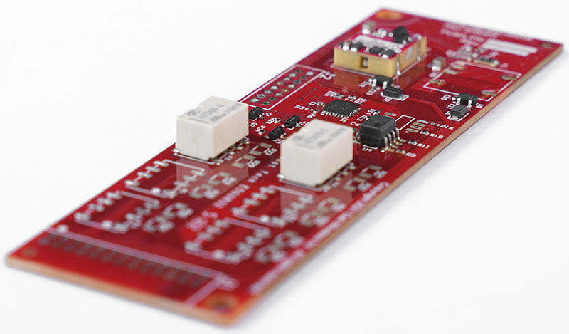
PiP (Pin-in-Paste), also known as Paste-in-Hole or Intrusive Reflow, is a hybrid assembly technique that allows through-hole components to be soldered during the SMT reflow process. This simplifies assembly by eliminating a separate wave soldering or manual soldering step, which is valuable for turnkey projects​ seeking efficiency.

How it works:

  • The PCB goes through the standard solder paste printing process.
  • Solder paste is deposited not only on SMD pads but also into the plated through-holes (PTHs) intended for PiP components.
  • SMT components are placed as usual.
  • PiP components​ (typically connectors or larger electromechanical parts with long leads) are inserted into the paste-filled holes. This can be done manually or with automated insertion equipment.
  • The entire assembly then passes through the reflow oven. The solder paste in the PTHs melts, flows, and creates a fillet, soldering the PiP component in place.

Advantages for Medical PCBA:

  • Process Simplification:​ Reduces the number of soldering stages, lowering cost and cycle time.
  • Improved Reliability:​ Can create more robust solder joints for heavy components compared to wave soldering.
  • Design Flexibility:​ Useful for mixed-technology boards where a few through-hole parts are needed alongside dense SMT.

Considerations:

Successful PiP requires careful design (adequate PTH size, solder paste volume calculation), specialized stencil design, and process validation to ensure complete hole fill and avoid solder voids.
SMT PCBA Process

How Is SMT Process Validation Performed In Mass Production?

SMT process validation​ is a formal, documented procedure that provides high confidence that a specific SMT process will consistently produce a PCBA meeting all predetermined quality and regulatory requirements. For mass production of medical devices, it is a mandatory gate before commercial launch.

The validation follows a structured, three-phase approach often aligned with the Installation Qualification (IQ), Operational Qualification (OQ), and Performance Qualification (PQ)​ framework.

  1. Installation Qualification (IQ):​ Verifies that the SMT production line​ equipment (printer, SPI, placer, oven) is correctly installed according to manufacturer specifications and site requirements. This includes checking utilities, calibrations, and software versions. Documentation: Equipment manuals, calibration certificates, installation checklists.
  2. Operational Qualification (OQ):​ Demonstrates that the installed equipment can operate consistently within established limits and tolerances under “worst-case” scenarios. This involves running the machines with test programs and challenging conditions.
    • Example OQ Tests:
      • Printer:​ Repeatability of paste volume across multiple prints.
      • Placer:​ Accuracy and repeatability of placement using a test board.
      • Reflow Oven:​ Verification of thermal profile consistency across all zones and across the conveyor width.
  3. Performance Qualification (PQ):​ Also known as Process Validation, this is the most critical phase. It proves that the entire, integrated process, using production-intent materials, can consistently produce acceptable product.
    • A validation lot (typically 3 consecutive production runs) is manufactured.
    • The entire SMT PCBA process flow​ is executed under standard operating procedures.
    • Every unit is subjected to comprehensive inspection and testing (visual, AOI, AXI, functional test).
    • Data is collected and analyzed to prove the process is stable and capable (using statistical tools like Cpk).
    • The outcome is a definitive report stating whether the process is validated for mass production.

For a medical device manufacturer, a completed validation package is a cornerstone of the Design History File (DHF) and is essential for regulatory submissions to bodies like the FDA. It is the ultimate proof that the manufacturing process is under control.
SMT PCBA Process

In summary, the SMT PCBA process​ is a complex yet precisely engineered sequence that forms the critical link between electronic design and a reliable, manufacturable medical device. Mastering this process—from the SMT process flow chart​ to real-time process control​ with metrics like CPK—is what separates a basic assembler from a qualified medical manufacturing partner.

This article has detailed the steps, controls, and validation frameworks necessary to achieve the reliability demanded by turnkey medical projects. Success hinges on automation, data-driven engineering, and a culture of continuous improvement.

At EBest Circuit (Best Technology), we have built our service around this principle. Our professional ODM SMT PCBA rapid patch processing​ is supported by a SMT production line​ equipped with advanced inspection technology and governed by a strict ISO 13485 quality system. We understand that for medical devices, the process isthe product. Pls feel free to contact our engineering team anytime at sales@bestpcbs.com​ to discuss your project requirements.

FAQs

How Is A PCBA Different From A PCB?

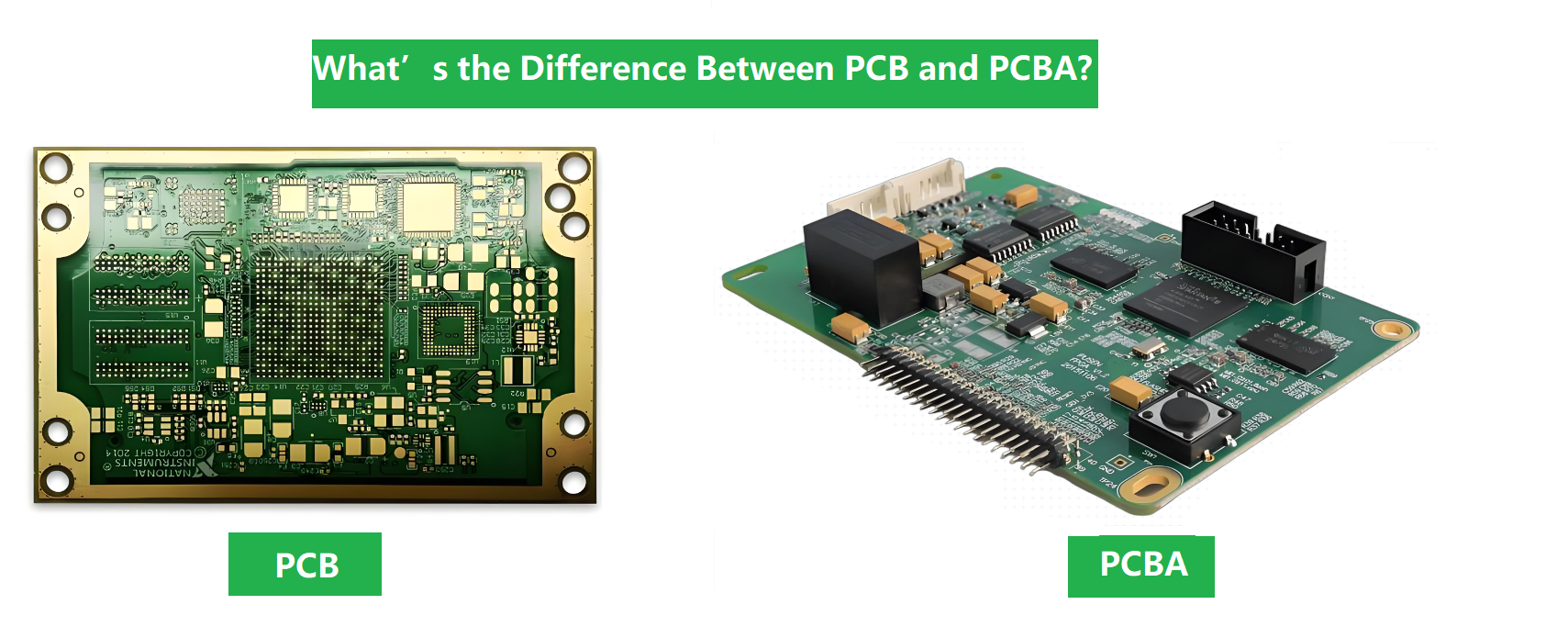
A PCB (Printed Circuit Board)​ is the bare, unpopulated board—just the laminate, copper traces, and solder mask. A PCBA (Printed Circuit Board Assembly)​ is the completed, functional board after all electronic components (SMT and/or through-hole) have been soldered onto it. The SMT PCBA process​ is what transforms a PCB into a PCBA.

What Is The Difference Between PCB And SMT?

This is a common point of confusion. PCB​ refers to the physical board itself. SMT (Surface Mount Technology)​ refers to one of the primary methods used to assemble components onto that PCB. SMT is a PCB assembly process, not the board.

How Do SMT Assembly Services Handle Component Availability?

Professional ODM SMT PCBA rapid patch processing​ partners manage this proactively. They maintain long-term relationships with franchised distributors, use component market analysis tools to forecast shortages, and offer DFM (Design for Manufacturability)​ reviews early in the design phase to suggest alternates for parts at risk of obsolescence, which is vital for the long lifecycles of medical devices.

What SMT Component Sizes Are Hardest To Assemble?

The greatest challenges come at the extremes of miniaturization: 01005 (0.4mm x 0.2mm)​ and smaller passive components, and ultra-fine-pitch components​ (e.g., 0.3mm pitch BGAs or CSPs). These require ultra-high-precision SMT pick and place machines, specialized stencil designs, and exquisite process control to avoid defects like bridging or misplacement.

What Are Typical Turnaround Times For SMT Assembly Services?

Turnaround time depends on project complexity, layer count, component sourcing, and quantity. For a standard prototype run with all parts in stock, rapid patch processing​ can be as quick as 24-72 hours​ for SMT assembly. For new medical projects requiring full process validation and regulatory documentation, the initial timeline will be longer to ensure quality, with subsequent production runs following a predictable schedule.
You may also like

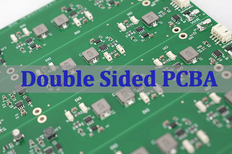
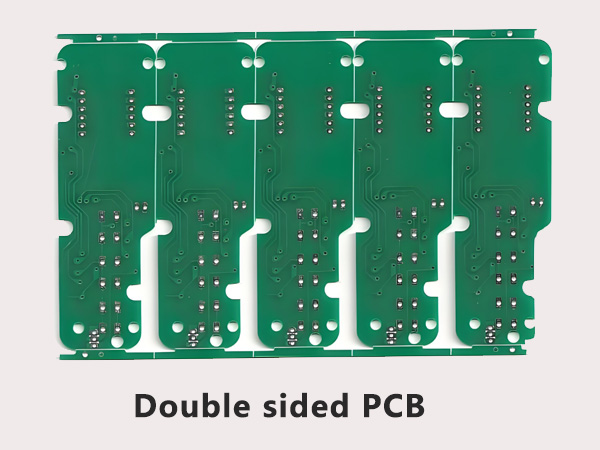
Double Sided PCBA Manufacturer with 20 Years of Production Experience

January 23rd, 2026

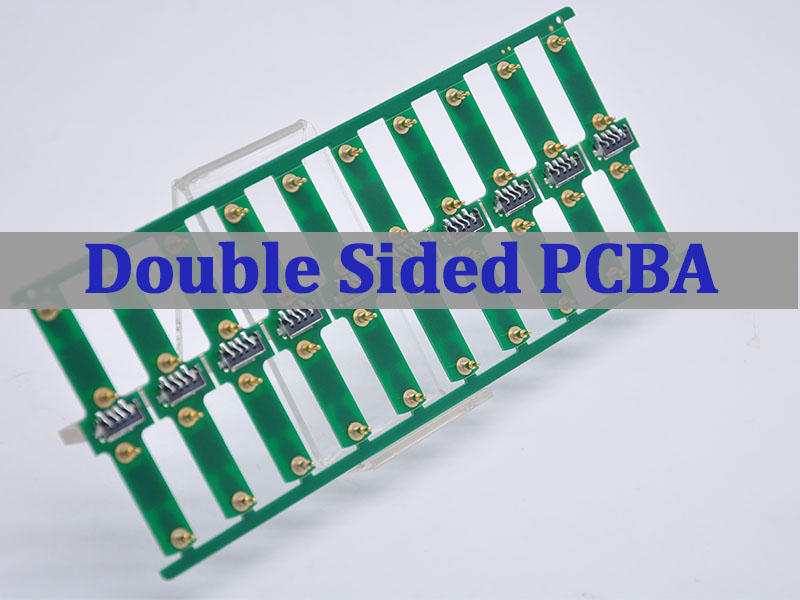
Double sided PCBA refers to a printed circuit board assembly where components are mounted and soldered on both sides of the PCB, enabling higher circuit density and more functional integration within a compact footprint. This article explains how double sided PCBA production works, when it should be selected, what risks commonly occur during assembly, and how an experienced manufacturer controls quality, cost, and delivery across the full production lifecycle.

Why Do Double Sided PCBA Projects So Often Run Into Trouble?

  • DFM issues are discovered after parts are ordered, forcing rework or redesign.
  • Double reflow introduces alignment and solder joint reliability risks.
  • BOM choices look acceptable on paper but fail under real supply constraints.
  • Quality varies between batches due to inconsistent process control.
  • Communication gaps slow down prototype-to-production transitions.

A double sided PCBA manufacturer with long-term production experience addresses these risks systematically rather than reactively.

  • Perform DFM review and process validation before material commitment.
  • Control double-sided reflow profiles and fixture strategy to stabilize yield.
  • Optimize BOMs with lifecycle checks and approved alternates.
  • Apply standardized inspection and quality checkpoints across all builds.
  • Use clear engineering communication workflows to reduce iteration cycles.

EBest Circuit (Best Technology) is a professional PCB and PCBA manufacturer with over 20 years of double sided PCBA production experience, serving more than 1,800 customers and 10,000 engineers worldwide. With in-house PCB fabrication, PCBA assembly, certified quality systems, and a digitalized production workshop, we help OEM teams move from prototype to volume. For technical consultation or quotations, pls feel free to contact us via sales@bestpcbs.com.

Double Sided PCBA

What Does Double Sided PCBA Involve In A Production Assembly Program?

A production-level double sided PCBA program includes more than placing parts on both sides of a board. It is a coordinated manufacturing system.

Key Elements Involved

  • Engineering Review – DFM, DFA, and process feasibility checks.
  • PCB Fabrication Alignment – Stack-up, finish, and panelization matched to assembly needs.
  • Component Preparation – Moisture control, polarity validation, and alternate sourcing.
  • Double-Sided Assembly – Controlled first-side and second-side reflow sequencing.
  • Inspection And Testing – AOI, X-Ray (when required), and functional validation.

A structured assembly program ensures that double sided PCBA remains stable and repeatable at production scale.

Double Sided PCBA

What Is The Typical Double Sided PCB Manufacturing Process From Design To Assembly?

The manufacturing process must account for thermal, mechanical, and inspection challenges unique to double sided boards.

Typical Process Flow

  • PCB fabrication with defined copper balance and solder mask design.
  • First-side SMT placement and reflow.
  • Board flipping with fixture support.
  • Second-side SMT placement and reflow.
  • AOI and selective inspection.
  • Through-hole assembly if required.
  • Final test and shipment.

Process discipline is critical to prevent cumulative defects introduced during multiple thermal cycles.

When Should Engineers Choose Double Sided PCB Design Over Single-Sided PCB?

Double sided PCB design is selected when functional density and routing flexibility outweigh the simplicity of single-sided PCB layouts.

Typical Selection Criteria

  • Circuit density exceeds single-sided routing capability.
  • Signal integrity benefits from shorter interconnect paths.
  • Board size constraints limit expansion.
  • Cost pressure makes multilayer PCB unnecessary.
  • Product requires moderate complexity with controlled assembly risk.

To wrap up, double sided PCB design often represents the best balance between functionality and manufacturing cost.

What Are Common Double-Sided PCB Applications In Modern Electronic Products?

Double-sided PCB applications span a wide range of industries where space efficiency and cost control are critical.

Common Applications

  • Industrial control modules
  • Power management boards
  • Consumer electronics
  • Automotive subassemblies
  • Communication interface boards

To summarize‌, double sided PCBA remains a workhorse solution for modern electronics across multiple sectors.

What Factors Affect Quality In China Double Sided PCBA Production?

China double sided PCBA quality depends more on process governance than on geography.

Key Quality Factors

  • DFM depth and timing
  • Component sourcing discipline
  • Reflow profile stability
  • Inspection coverage and standards
  • Production traceability

To wrap things up, choosing a China-based manufacturer with mature controls is essential for consistent quality.

What Assembly Risks Are Common In Double Sided PCBA Production?

Double sided PCBA introduces specific risks that must be managed proactively.

Common Assembly Risks

  • Component shift during second reflow
  • Tombstoning on small passives
  • Shadowing effects during AOI
  • Thermal stress on sensitive devices
  • Yield loss from inconsistent handling

To sum up, experienced manufacturers mitigate these risks through fixturing, profiling, and inspection strategy.

How Does Double Sided PCBA Compare With Multilayer PCBA In Cost Structure?

From a cost perspective, double sided PCBA often occupies a middle ground between simplicity and complexity.

Cost Structure Comparison

AspectDouble Sided PCBAMultilayer PCBA
PCB CostLowerHigher
Assembly ComplexityModerateHigh
Yield SensitivityMediumHigh
Design FlexibilityModerateVery High

In essence, double sided PCBA is often the most cost-effective solution when multilayer routing is not strictly required.

Double Sided PCBA

Overall, double sided PCBA enables compact, cost-efficient electronic manufacturing when supported by disciplined engineering and production control. This article reviewed the production scope, manufacturing process, application scenarios, quality factors, assembly risks, and cost structure considerations associated with double sided PCBA.

As a double sided PCBA manufacturer with 20 years of production experience, EBest Circuit (Best Technology) combines engineering depth, certified quality systems, digital traceability, and fast turnaround to help OEMs achieve stable, scalable results. For project evaluation or quotations, pls feel free to contact us via sales@bestpcbs.com.

FAQs

What is the difference between single sided and double sided PCB?

A single sided PCB places components on one side only, while a double sided PCB allows components on both sides, increasing circuit density and routing options.

How are double-sided PCBs assembled?

Double-sided PCBs are assembled through sequential placement and reflow, typically soldering one side first, then flipping the board and assembling the second side with controlled fixturing and thermal profiles.

You may also like

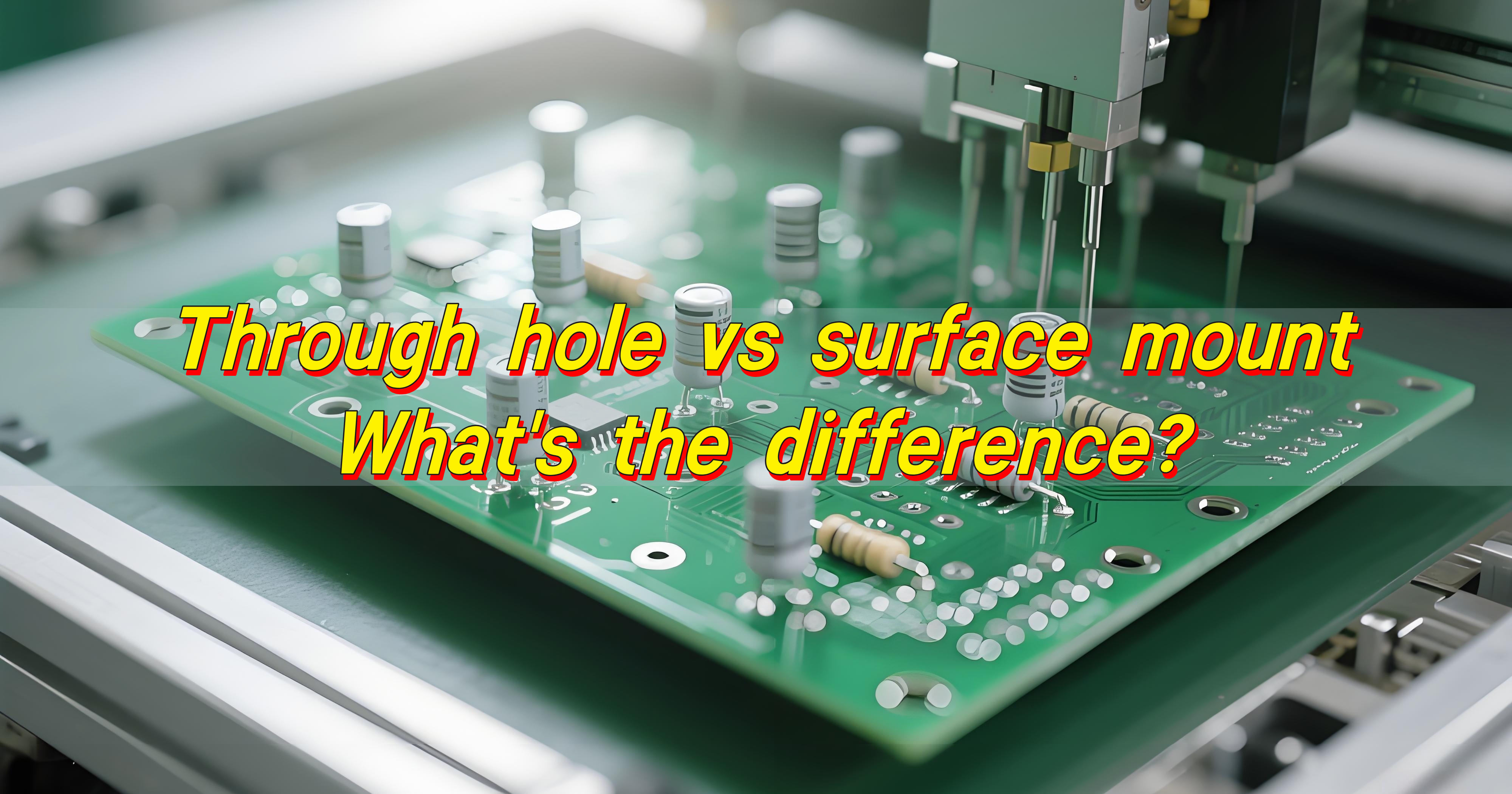
Through Hole vs Surface Mount – What’s the Difference?

January 23rd, 2026

Through hole vs surface mount are the two main methods for attaching electronic components to a printed circuit board, and each serves different design and manufacturing needs.

Through Hole vs Surface Mount – What’s the Difference?

What Is the Difference Between SMT and THT?

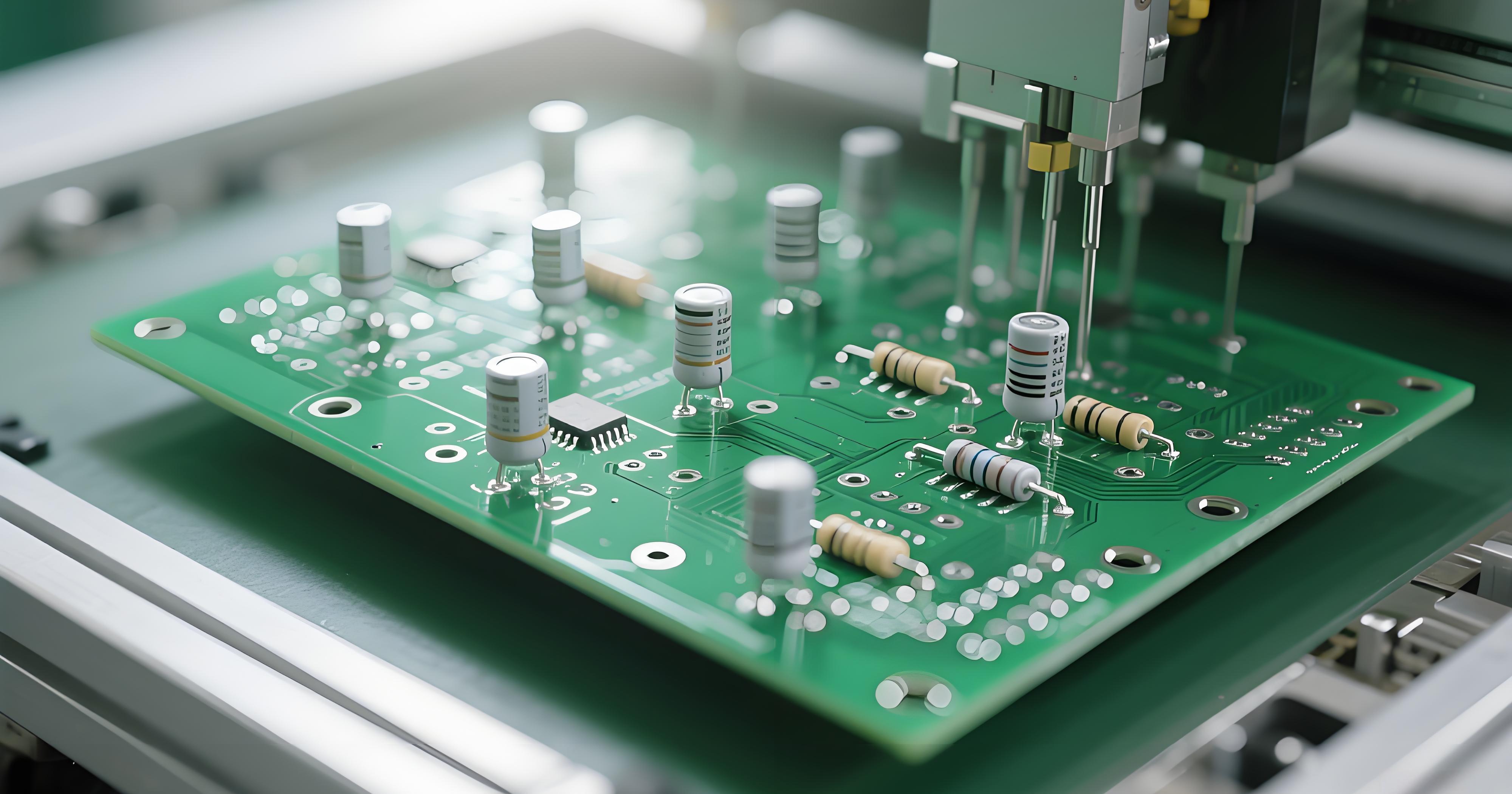
Through hole technology, often called THT or through hole mount, uses component leads that pass through drilled holes in the PCB. These leads are inserted, soldered on the opposite side, and mechanically anchored by the plated hole wall. This method relies heavily on through hole drilling, copper plating, and solder fillets that form on both sides of the board.

Surface mount technology, or SMT, works very differently. Components are placed directly onto pads on the PCB surface. No lead passes through the board. Instead, solder paste holds the part in place during reflow. This approach supports compact layouts, fine-pitch parts, and high-speed automated placement.

From a manufacturing view, the difference between PCB through hole vs surface mount affects many steps:

  • Through hole requires drilling, desmear, and hole plating
  • SMT focuses on stencil printing, placement accuracy, and reflow profiling
  • THT boards often need wave soldering or selective soldering
  • SMT boards rely on reflow soldering and AOI inspection

At EBest Circuit (Best Technology), mixed-technology boards are common. Many designs use surface mount components for logic and control, while keeping through hole components for connectors, transformers, or power devices.

What Are the Disadvantages of SMT?

Surface mount technology delivers speed and density, but it is not without limitations. 

  • One challenge is mechanical strength. Surface mount parts rely entirely on solder joints attached to surface pads. Under heavy vibration or mechanical stress, these joints need proper pad design and solder volume to remain stable.
  • Thermal handling can also be more demanding. Small surface mount packages dissipate heat through pads and copper planes. Poor thermal design may cause overheating if copper balance or via placement is incorrect.
  • Another consideration is inspection and rework. Fine-pitch SMT components require magnification, X-ray inspection, and skilled rework processes.

Common SMT challenges include:

  • Sensitivity to solder paste quality
  • Tight process windows in reflow profiles
  • Increased difficulty in manual rework for very small packages

Experienced manufacturers, including EBest Circuit (Best Technology), mitigate these issues through controlled stencil design, profile tuning, and process validation.

What Are the Disadvantages of Through-Hole Soldering?

When reviewing surface mount vs through hole soldering, through hole soldering presents a different set of trade-offs.

  • The most visible limitation is space. Through hole components occupy both sides of the PCB and require clearance around each drilled hole. This reduces routing density and limits miniaturization.
  • Manufacturing time is another factor. Through hole soldering often involves manual insertion or slower automated processes. Wave soldering is efficient for large volumes, but setup and fixturing take time.
  • Cost is also influenced by drilling. Each plated hole adds fabrication steps, tool wear, and inspection effort. For dense designs, through hole drilling increases PCB cost compared to pure SMT layouts.

Despite these points, through hole technology remains valuable. Its disadvantages are mostly related to scale and size, not reliability. For power and structural roles, its benefits often outweigh its limits.

Through Hole vs Surface Mount – What’s the Difference?

Is Surface Mount Better Than Through-Hole?

Surface mount excels in high-density electronics. It supports smaller boards, faster assembly, and lower per-unit cost at volume. Consumer electronics, IoT devices, and compact control modules rely heavily on SMT for this reason.

Through hole shines where strength and current handling matter. Large electrolytic capacitors, power inductors, relays, and connectors benefit from the mechanical anchor of plated holes.

What Is the Main Advantage of SMT Over Through-Hole Technology?

The main advantage of SMT over through hole technology is efficiency. This efficiency appears in several practical ways.

  • First, component density increases. Surface mount packages are smaller and do not require holes, allowing more components per square inch.
  • Second, automation improves consistency. SMT lines place thousands of parts per hour with repeatable accuracy.
  • Third, electrical performance benefits. Shorter leads reduce parasitic inductance and resistance, which helps high-speed and high-frequency designs.

Key advantages include:

  • Reduced board size
  • Faster assembly cycles
  • Improved signal integrity
  • Lower material usage at volume

What Is THT Used For?

Through hole technology remains essential in many applications. Its use is deliberate

THT is commonly used for components that experience physical stress or carry high current. Power supplies, industrial controllers, and automotive modules often include through hole parts for durability.

Typical through hole components types include connectors, transformers, large capacitors, and mechanical switches. These parts benefit from the mechanical bond formed by the plated hole and solder fillet.

THT is also common in prototypes and low-volume builds. Manual insertion allows flexibility during early design stages. Educational boards and test fixtures often rely on through hole mount parts for ease of handling.

At EBest Circuit (Best Technology), THT is frequently integrated into hybrid PCBA projects. Selective soldering and controlled wave soldering ensure reliable joints without compromising SMT sections.

Through Hole vs Surface Mount – What’s the Difference?

What Is the Golden Rule of Soldering?

The golden rule of soldering is simple: heat the joint, not the solder.

This principle applies to both surface mount soldering vs through hole processes. Proper solder joints form when the pad and lead reach the correct temperature, allowing solder to flow naturally.

Good soldering also requires clean surfaces, stable temperature control, and adequate flux. Rushing the process leads to cold joints or weak bonds.

A reliable solder joint shows smooth fillets, full wetting, and consistent shine. These visual cues reflect sound metallurgical bonding, not just appearance.

What Is the Best Flux for Through-Hole Soldering?

Choosing the right flux improves through hole soldering quality and repeatability. Flux removes oxidation and promotes solder flow.

For most electronic assemblies, no-clean flux is widely used. It leaves minimal residue and simplifies post-solder cleaning. Rosin-based flux offers strong activity but may require cleaning.

Water-soluble flux provides excellent wetting but demands thorough rinsing. It is often used in controlled environments with established wash processes.

The best flux depends on the soldering method, board material, and reliability requirements. Manufacturers like EBest Circuit (Best Technology) select flux types based on assembly complexity and end-use standards.

Can You Hand Solder a Surface Mount?

Yes, you can hand solder surface mount components. While SMT is designed for automation, skilled technicians routinely hand solder prototypes, repairs, and small batches.

The process requires fine tips, steady temperature control, and magnification. Proper flux application makes a significant difference in wetting and joint quality.

Hand soldering works best for larger surface mount packages such as SOIC, QFN, and discrete passives. Very fine-pitch devices demand more experience.

Through Hole vs Surface Mount – What’s the Difference?

What Is the Most Common Problem With Soldering?

The most common problem with soldering is insufficient wetting. This issue affects both surface mount vs through hole soldering.

Poor wetting occurs when solder fails to bond smoothly to the pad or lead. Causes include contamination, low temperature, or inadequate flux.

Other frequent issues include solder bridges, voids, and uneven fillets. These problems are preventable with process control and inspection.

Conclusion:

Understanding through hole vs surface mount is about matching technology to function. Surface mount technology supports compact, high-speed, and high-volume electronics. Through hole technology delivers strength, durability, and dependable power handling.

EBest Circuit (Best Technology) works closely with customers to select the right combination of surface mount and through hole processes. If you have questions about component selection, soldering methods, or mixed-technology PCBA projects, professional guidance can save time and reduce risk.

For technical inquiries or sourcing support, please contact sales@bestpcbs.com

You may also like

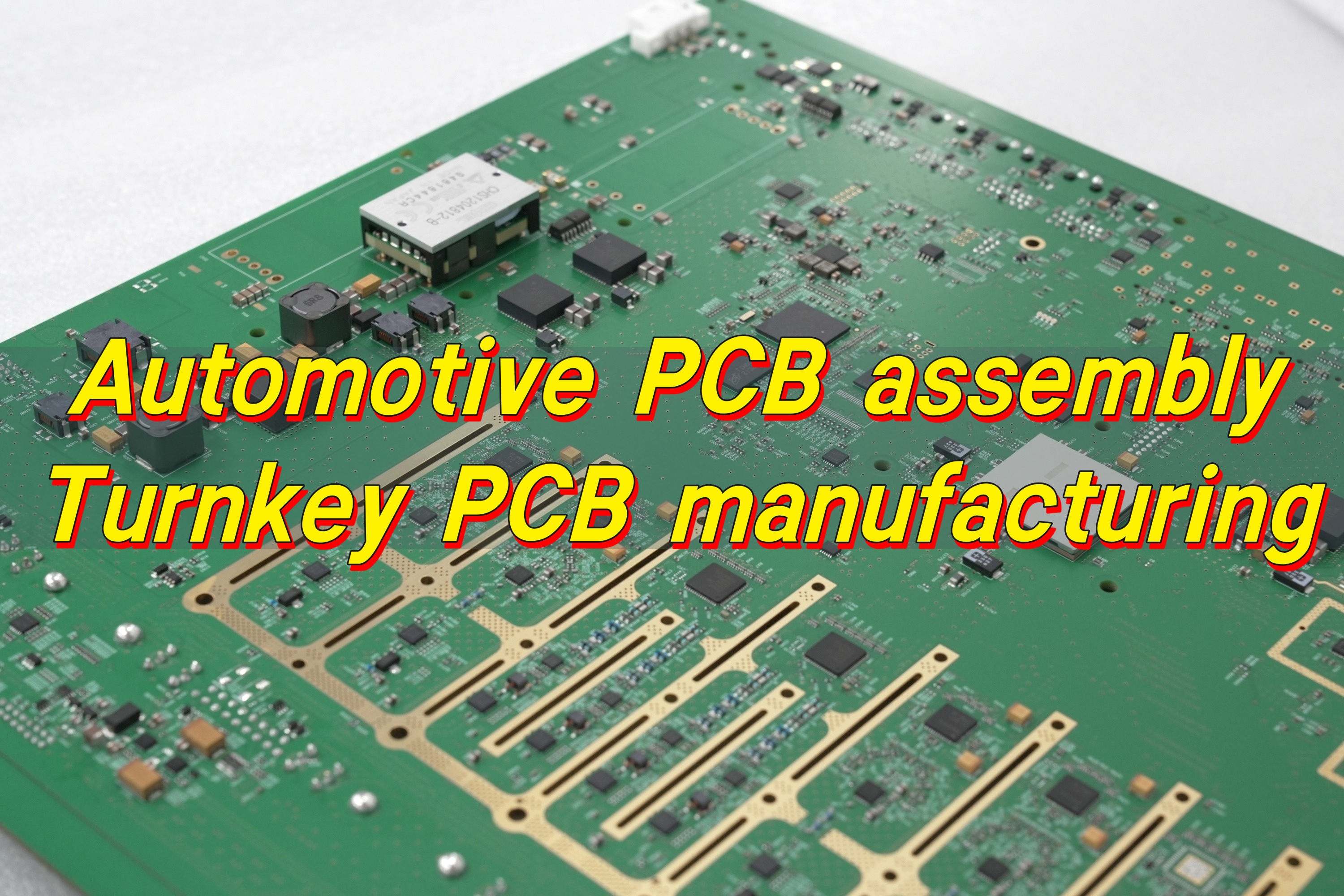
Automotive PCB Assembly, Turnkey PCB Manufacturing

January 22nd, 2026

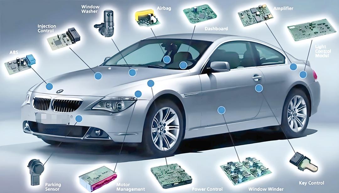
Automotive PCB assembly is the backbone of modern vehicle electronics, powering systems such as engine control units, ADAS modules, infotainment, battery management, and body control units. Unlike consumer electronics, automotive boards must operate reliably under vibration, heat, moisture, and long service cycles.

This demands strict process control, automotive-grade components, traceable materials, and compliance with quality standards to ensure consistent performance over millions of driving miles.

What is automotive control system PCB assembly?

Automotive control system PCB assembly refers to the process of assembling printed circuit boards used in vehicle control units. These boards form the electronic backbone of automotive systems that monitor, regulate, and respond to real-time vehicle conditions.

A control system PCB does not operate in isolation. It interacts with sensors, actuators, power modules, and communication networks throughout the vehicle. The assembly process must therefore deliver electrical stability, mechanical strength, and predictable performance over many years of operation.

Automotive control system PCBs are commonly found in engine control units, battery management systems, transmission controllers, braking systems, and body control modules. Each board must withstand continuous thermal cycling, electrical noise, and mechanical stress.

Automotive PCB assembly differs from standard PCB assembly in several important ways. Materials are selected for thermal endurance. Solder joints are designed for vibration resistance. Process control is far stricter. Documentation and traceability are mandatory rather than optional.

Control system PCB assembly usually involves multilayer boards with fine-pitch components, power devices, and mixed-technology assembly. Surface mount technology is widely used, while through-hole components remain common for connectors and high-power parts.

How much does automotive PCB assembly cost?

Automotive PCB assembly cost is influenced by several interrelated factors. There is no fixed price because each project carries unique technical and compliance requirements.

  • Board complexity is a primary driver. Layer count, board thickness, copper weight, and impedance control all affect fabrication cost. Dense layouts increase assembly difficulty and inspection time.
  • Component selection also has a major impact. Automotive-grade components are more expensive than commercial equivalents. Long-term availability and approved vendor lists further influence sourcing cost.
  • Assembly process requirements shape pricing as well. Fine-pitch components, BGA packages, and mixed SMT and through-hole designs require specialized equipment and skilled operators.
  • Testing and quality control contribute significantly to total cost. Automotive programs typically require multiple inspection stages and functional testing.

When evaluating automotive PCB assembly factories, cost should be viewed in context. A lower unit price may conceal risks related to yield loss, field failure, or supply instability.

Many OEMs prefer turnkey PCB manufacturing because it consolidates costs into a single controlled workflow. EBest Circuit (Best Technology) supports this model by offering turnkey PCB assembly without MOQ requirements, allowing customers to balance cost control with production flexibility.

What testing is required in automotive PCB assembly?

Testing is a defining element of automotive PCB assembly. It verifies that each assembled board meets functional and reliability expectations before entering a vehicle system.

  • Visual inspection is the first layer of control. Automated optical inspection checks solder joints, component placement, and polarity. This step catches surface-level defects early in the process.
  • Electrical testing follows. In-circuit testing verifies component values, connectivity, and basic electrical behavior. It helps identify assembly issues that visual inspection cannot detect.
  • Functional testing is essential for control system PCBs. Boards are powered and operated under simulated conditions to confirm correct behavior. This test validates firmware interaction and signal response.
  • For certain applications, environmental testing is required. Thermal cycling exposes boards to repeated temperature changes. Vibration testing evaluates mechanical robustness.
  • Traceability supports all testing activities. Each board is linked to material batches, process records, and test results.

A reliable automotive PCB assembly factory integrates testing into production rather than treating it as a final checkpoint. EBest Circuit (Best Technology) applies multi-stage inspection and testing as part of its turnkey PCB manufacturing process, supporting stable quality without unnecessary delay.

How long does PCB assembly take?

PCB assembly lead time depends on project scope, supply chain conditions, and testing requirements. Automotive projects often prioritize consistency over speed, yet efficient scheduling remains important.

  • Prototype assembly usually takes longer than consumer electronics prototypes. Engineering review, process setup, and validation testing add time but reduce downstream risk. For small-volume production, lead times typically range from one to three weeks. This includes material preparation, assembly, inspection, and functional testing.
  • Mass production lead times depend on order size and production planning. Once a process is validated, cycle times become more predictable. Long-term agreements often allow for stable scheduling.
  • Component availability plays a major role. Automotive-grade components may have longer lead times. A turnkey PCB assembly partner can mitigate this risk through proactive sourcing and inventory planning.

EBest Circuit (Best Technology) supports flexible lead times by integrating PCB fabrication, component sourcing, and assembly under one system. This approach reduces coordination delays and helps maintain predictable delivery schedules.

What is automotive PCB assembly used for?

Automotive PCB assembly supports a wide range of vehicle systems. Each application has its own technical focus, yet all share a need for dependable electronic control.

  • Powertrain systems rely on PCBs to manage engine performance, fuel delivery, and emissions. These boards must operate reliably under high temperature and electrical load.
  • Safety systems depend on precise signal processing. Airbag controllers, braking systems, and stability control units use PCBs that must respond instantly and accurately.
  • Body electronics manage lighting, climate control, and access systems. While operating conditions may be less severe, long-term reliability remains essential.
  • Electric and hybrid vehicles introduce new requirements. Battery management systems and power control units rely on PCBs that handle high currents and monitor complex parameters.
  • Infotainment and connectivity systems also use automotive PCB assembly. These boards integrate communication interfaces while meeting automotive durability standards.

Across all these uses, automotive PCB assembly ensures that electronic systems perform consistently throughout the vehicle’s service life.

What challenges exist in automotive control system PCB assembly?

Automotive control system PCB assembly presents technical and operational challenges. These challenges require careful planning rather than reactive problem solving.

  • Thermal management is a constant concern. Control systems often operate near heat sources. Poor thermal design or assembly can lead to premature failure.
  • Vibration and mechanical stress affect solder joint integrity. Assembly processes must account for continuous movement and shock.
  • Component lifecycle management adds complexity. Automotive programs often last many years. Ensuring component availability requires strategic sourcing.
  • Process consistency is another challenge. Automotive quality expectations leave little room for variation. Assembly parameters must remain stable over long production runs.
  • Compliance requirements introduce additional workload. Documentation, traceability, and audit readiness are not optional in automotive manufacturing.

Despite these challenges, structured manufacturing processes can mitigate risk. Working with an experienced automotive PCB assembly manufacturer helps translate design requirements into stable production outcomes.

How to choose an automotive control system PCB assembly factory?

Selecting the right automotive control system PCB assembly factory is a strategic decision. It affects product reliability, supply continuity, and total cost of ownership.

  • Experience in automotive projects matters. A factory familiar with automotive standards understands the importance of process discipline.
  • Manufacturing capability should align with product requirements. This includes multilayer PCB fabrication, fine-pitch assembly, and power electronics handling.
  • Quality systems are critical. Look for structured inspection, testing, and traceability practices. These systems support long-term program stability.
  • Supply chain management is equally important. Automotive components require careful sourcing and lifecycle planning.
  • Communication and engineering support often determine project success. A responsive partner helps resolve issues early and supports design optimization.

EBest Circuit (Best Technology) positions itself as a professional PCB manufacturer offering PCB prototyping, design, and assembly services. Its turnkey PCB assembly model without MOQ requirements supports both development and production stages.

Why select a professional automotive PCB assembly factory?

A professional automotive PCB assembly factory provides more than production capacity. It delivers process control, accountability, and confidence.

Professional manufacturers invest in equipment, training, and quality systems. These investments reduce variation and improve long-term reliability.

Turnkey PCB manufacturing further strengthens this approach. By managing the entire process, risks related to handoffs and miscommunication are reduced.

For automotive programs, reliability is not negotiable. Choosing a professional automotive PCB assembly factory supports consistent performance throughout the vehicle lifecycle.

EBest Circuit (Best Technology) offers turnkey PCB assembly services without MOQ requirements, supporting automotive customers from early prototypes to stable production.

Conclusion:

Automotive PCB assembly plays a central role in modern vehicle electronics. Control system PCBs support safety, performance, and efficiency across many applications.

For professional support in automotive PCB assembly and turnkey PCB manufacturing, contact sales@bestpcbs.com to discuss your project requirements.

You may also like

EMS PCB Assembly Manufacturer | EBest Circuit (Best Technology)

January 20th, 2026

EMS PCB assembly refers to Electronics Manufacturing Services that cover more than just assembling a printed circuit board. In a true EMS model, the provider manages the full scope of manufacturing activities required to turn a design into a production-ready product.

Typical EMS PCB assembly services include:

  • Coordination of PCB fabrication
  • Component sourcing and lifecycle management
  • SMT and through-hole assembly
  • Inspection, testing, and quality documentation
  • Ongoing production and engineering support

For companies moving beyond simple prototypes, EMS PCB assembly offers a structured approach to manufacturing that reduces internal workload and improves consistency.

EMS PCB Assembly Manufacturer | EBest Circuit (Best Technology)

EMS PCB Assembly vs Standard PCB Assembly Service

The difference between EMS PCB assembly and standard PCB assembly becomes apparent as project complexity increases.

A standard PCB assembly service usually focuses on:

  • Build-to-print assembly
  • Limited responsibility beyond soldering and inspection
  • Customer-managed materials and logistics

An EMS PCB assembly service, by contrast, takes responsibility for:

  • Design-for-manufacturing feedback
  • Component sourcing and approved substitutions
  • Coordinated planning across fabrication, assembly, and testing
  • Quality control and traceability

In practical terms, standard PCB assembly executes instructions, while EMS PCB assembly manages the manufacturing outcome.

Why Choose EMS PCB Assembly Service?

Companies choose EMS PCB assembly when they need more control and fewer surprises during production.

Common reasons include:

  • Smoother transition from prototype to production
  • Reduced supply-chain risk through managed sourcing
  • More predictable quality and yield
  • Lower total cost over time, even if unit prices are higher

For products with long lifecycles, compliance requirements, or complex BOMs, EMS PCB assembly provides a level of stability that transactional assembly services cannot.

What Are the Most Common Risks in EMS PCB Assembly?

EMS PCB assembly is not risk-free. When poorly managed, it can introduce new challenges instead of solving existing ones.

The most common risks include:

  • Prototype success that does not translate into production yield
  • Unapproved component substitutions due to shortages
  • Insufficient testing coverage for real-world use
  • Communication gaps between engineering, sourcing, and production

Our approach prevents these issues through:

  • Early DFM / DFT engineering review
  • BOM-level lifecycle and sourcing analysis
  • Defined process controls across all build stages
  • Formal change management and traceability

Risk is not eliminated—but it is controlled before it affects delivery or reliability.

What Are the Most Common Risks in EMS PCB Assembly?

Factors That Affect EMS PCB Assembly Cost

EMS PCB assembly cost is influenced by far more than assembly labor.

Key cost factors include:

  • PCB material selection and layer count
  • Component availability and sourcing channels
  • Assembly complexity and package density
  • Inspection, testing, and documentation requirements

We focus on total cost of ownership, helping customers avoid hidden expenses caused by rework, delays, or redesigns later in production.

Top 7 EMS PCB Assembly Service Providers

The EMS market includes providers with very different strengths and target customers. Below are seven well-known EMS PCB assembly service providers, each serving distinct needs:

EMS ProviderPrimary Market FocusCore EMS PCB Assembly StrengthsBest Fit For
Best TechnologyPrototype to low / mid-volume, high-mix projectsEngineering-driven EMS PCB assembly, strong DFM/DFT support, transparent component sourcing, flexible volumesStartups, SMEs, industrial & medical projects needing flexibility and close engineering support
JabilGlobal, high-volume manufacturingMassive global footprint, advanced supply-chain management, automation at scaleLarge OEMs with stable, high-volume, multinational programs
FlexHigh-volume, complex supply chainsEnd-to-end EMS, strong logistics and digital manufacturing capabilitiesEnterprises requiring global production and supply-chain resilience
SanminaHigh-reliability & regulated industriesComplex PCB assembly, strong compliance systems, aerospace & industrial focusAerospace, defense, medical, and mission-critical electronics
CelesticaAdvanced manufacturing & cloud infrastructureAutomation-heavy EMS, digital manufacturing processesData-center, networking, and advanced industrial electronics
PlexusEngineering-intensive EMS projectsStrong NPI support, lifecycle management, regulated-market expertiseProducts with long lifecycles and frequent engineering changes
Benchmark ElectronicsIndustrial, medical, aerospaceBalanced EMS offering with emphasis on quality and complianceMedium-to-high complexity products in regulated sectors

Why Companies Choose Best Technology?

Not every project needs a global EMS giant. Many require engineering depth, flexibility, and accountability.

Best Technology is selected by customers who need:

  • Early engineering involvement, not post-design execution
  • Transparent, traceable component sourcing
  • Support for prototype, low-volume, and ongoing production
  • Stable quality systems suitable for demanding applications

We approach EMS PCB assembly as a long-term manufacturing partnership, not a transactional service.

Our EMS PCB Assembly Capabilities

Our facilities and processes support EMS PCB assembly projects across a wide range of complexity levels:

  • SMT, through-hole, DIP PCB & box building assembly
  • Various PCB types including HDI, RF, MCPCB, ceramic PCB, rigid flex PCB and so on
  • Mixed-technology and fine-pitch designs
  • BGA, QFN, QFP small chips
  • Prototype, low-volume, and medium-volume production
  • AOI, X-ray, and functional testing
  • Full documentation and traceability

All capabilities operate within a unified EMS framework to ensure consistency as production scales.

Is Our EMS PCB Assembly Right for Your Project?

Our EMS PCB assembly services are a strong fit if you:

  • Plan to scale beyond prototypes
  • Need sourcing stability and lifecycle management
  • Require predictable quality and delivery
  • Want engineering support, not just assembly capacity

If your priority is lowest unit price alone, a basic assembly vendor may be a better match.
If your priority is manufacturing confidence, EMS is the right model.

Common FAQs

1. What does EMS mean in PCB assembly?

    EMS stands for Electronics Manufacturing Services, covering sourcing, assembly, testing, and production coordination.

    2. Is EMS PCB assembly suitable for startups?

    Yes. Many startups use EMS partners to avoid redesigns and supply-chain issues as they scale.

    3. What is the typical MOQ for EMS PCB assembly?

    MOQ depends on project complexity. We support prototype and low-volume builds as well as ongoing production.

    4. How long does EMS PCB assembly usually take?

    Lead time varies by materials and complexity, typically ranging from several weeks to a few months.

    5. Can you manage component shortages?

    Yes. Component risk is addressed through sourcing strategy, approved alternates, and lifecycle analysis.

    6. What files are required to start?

    Gerbers, BOM, pick-and-place data, assembly drawings, and test requirements.

    Start Your EMS PCB Assembly Project

    If you are evaluating EMS PCB assembly and want to understand whether our approach fits your product, the next step is a technical discussion—not a sales pitch.

    Share your design files or project requirements, and our engineering team will review manufacturability, sourcing risk, and production readiness.

    👉 Request an EMS PCB Assembly Review

    You may also like

    Trusted Automotive PCBA with Full Traceability and Process Control

    January 20th, 2026

    Automotive PCBA​ is the engineered backbone of modern vehicles, integrating complex circuitry to control everything from infotainment to advanced driver-assistance systems (ADAS). This article explores the critical standards, manufacturing excellence, and partnership criteria essential for sourcing reliable automotive printed circuit board assemblies.

    Choosing the wrong automotive PCBA supplier exposes OEMs and Tier-1s to hidden risks that directly impact safety, timelines, and total lifecycle cost.

    • Reliability failures: Breakdowns under heat, vibration, or humidity.
    • Inconsistent quality: Weak traceability limits root-cause analysis.
    • Slow qualification: IATF 16949 and automotive approvals drag on.
    • Supply chain risk: Poor responsiveness across global programs.
    • Escalating costs: Rework and field failures inflate liability.

    These risks are mitigated by working with an automotive PCBA partner that embeds control, traceability, and quality discipline into every production stage.

    • Harsh-environment testing: Thermal cycling, vibration, HALT/HASS.
    • End-to-end traceability: Component-to-board barcode or RFID tracking.
    • Automotive frameworks: APQP, PPAP, and FMEA from program start.
    • Engineering partnership: Dedicated support and clear communication.
    • Process discipline: DFM analysis and SPC to prevent defects early.

    At EBest Circuit (Best Technology), we specialize in being your trusted automotive PCBA partner. As an IATF 16949 certified automotive PCBA​ manufacturer, we combine advanced process control with full material and production traceability to deliver high-reliability automotive electronics PCBA. Our expertise ensures your designs meet the stringent demands of the automotive industry. To review your technical requirements in detail, contact our team anytime at sales@bestpcbs.com.

    Automotive PCBA

    Top 10 Automotive PCBA Factories

    Selecting a factory requires evaluating technical capability, quality certification, and automotive focus. Here are ten leading global manufacturers known for their expertise in automotive PCBA assembly.

    • Flex Ltd.: A global leader in sketch-to-scale solutions, with extensive automotive PCBA​ factories​ worldwide and deep expertise in EV and ADAS systems.
    • Jabil Inc.: Offers comprehensive supply chain and manufacturing solutions for automotive, strong in electrification and connectivity PCBA​ automotive​ applications.
    • Sanmina Corporation: Provides high-mix, low-to-high volume manufacturing with a focus on complex, high-reliability automotive electronics PCBA​.
    • Benchmark Electronics: Specializes in engineering and manufacturing for demanding sectors, including advanced automotive PCBA​ for engine control units.
    • Venture Corporation: A leading provider of technology solutions, with strong capabilities in multilayer automotive PCBA​ production​ for sensing and control modules.
    • Zollner Elektronik AG: A German-based specialist in automotive-grade PCBA​, known for rigorous quality and serving premium European OEMs.
    • Kimball Electronics Inc.: An IATF 16949 certified​ manufacturer focused on durable electronics, with a robust portfolio in automotive sensing and lighting.
    • SIIX Corporation: A Japanese electronics company with a strong focus on quality and miniaturization for automotive components.
    • EBest Circuit (Best Technology): A specialized automotive PCBA​ manufacturer​ and trusted automotive PCBA​ partner​ emphasizing full traceability, process control, and rapid prototyping for complex boards.
    • Würth Elektronik eiSos Group: Known as a component supplier, it also offers automotive PCBA​ solutions​ through its manufacturing services, especially for PCB-based assemblies.

    The ideal factory choice depends on specific program needs, but leaders are distinguished by automotive-specific certifications, proven reliability, and technological depth.

    Automotive PCBA

    How Does Automotive PCBA Assembly Ensure Reliability Under Harsh Conditions?

    Automotive electronics face extreme temperatures, constant vibration, and potential moisture ingress. Reliability is engineered through a multi-layered approach in assembly and testing.

    1. Material Selection:​ Using high-Tg laminates, automotive-grade components, and specialized conformal coatings to withstand thermal stress and corrosion.
    2. Robust Soldering Processes:​ Controlled reflow soldering profiles and selective soldering ensure strong, void-free interconnections resistant to fatigue.
    3. Conformal Coating:​ Applying acrylic, silicone, or polyurethane coatings protects the automotive PCBA​​ from humidity, dust, and chemical contaminants.
    4. Advanced Testing Regimes:​ Reliability is validated through:
      • Thermal Cycling:​ Subjecting boards to extreme temperature swings.
      • Vibration & Shock Testing:​ Simulating years of road conditions.
      • HALT/HASS:​ Highly Accelerated Life/Stress Screening to find design and process weaknesses early.
    5. Mechanical Securement:​ Strategic use of brackets, adhesives, and potting to anchor components and boards against vibration.

    Through this systematic combination of design, material science, and validation, automotive PCBA assembly​ delivers the durability required for vehicle lifespans.

    Which Automotive PCBA Materials Content Meets Automotive Compliance Standards?

    Compliance is non-negotiable, governed by regulations like RoHS, REACH, and the automotive-specific GADSL (Global Automotive Declarable Substance List).

    • Base Laminate:​ Must be AEC-Q100 qualified. High-Tg FR-4 (Tg > 150°C) or specialized materials like polyimide are common for under-hood applications.
    • Copper & Surface Finish:​ Electroless Nickel Immersion Gold (ENIG) or Immersion Silver offer reliable, lead-free solderability and surface durability.
    • Components:​ All active and passive components should be rated for automotive temperature ranges (e.g., -40°C to +125°C or higher).
    • Solders & Pastes:​ Use of halogen-free, automotive-grade solder paste with proper alloy composition (e.g., SAC305) is standard.
    • Declarable Substances:​ A rigorous automotive PCBA materials content gadsl​ declaration from the manufacturer is essential. This documents the absence or controlled use of substances like lead, cadmium, mercury, and certain phthalates.

    Partnering with an automotive PCBA supplier​ that provides full material declarations and understands the evolving regulatory landscape is critical for compliance.

    Why Is IATF 16949 Certified Automotive PCBA Critical For OEM Programs?

    IATF 16949 is the definitive quality management standard for the automotive industry, extending beyond ISO 9001.

    • Mandatory for OEM & Tier-1 Supply:​ Most major automakers require this certification for direct suppliers.
    • Focus on Defect Prevention:​ It mandates core quality tools like Advanced Product Quality Planning (APQP) and Production Part Approval Process (PPAP), ensuring issues are resolved before mass production.
    • Risk Management:​ Requires Failure Mode and Effects Analysis (FMEA) to proactively identify and mitigate potential automotive PCBA failure​ risks.
    • Continuous Improvement:​ Embeds a culture of ongoing quality and efficiency improvements (Kaizen).
    • Supply Chain Confidence:​ An IATF 16949 certified automotive PCBA​ manufacturer demonstrates a systemic commitment to automotive-quality processes, reducing audit burden and program risk.

    This certification is a fundamental prerequisite, not just a badge, for any serious automotive PCBA manufacturer.

    How Are Automotive PCBA Failure Risks Identified And Controlled In Production?

    Proactive risk control is central to automotive manufacturing. The process is systematic and integrated.

    • Design Stage (DFMEA):​ Potential design-related failures are analyzed and mitigated through robust PCBA requirements for automotive electronic​ design.
    • Process Stage (PFMEA):​ Every manufacturing step is analyzed for potential errors (e.g., solder defects, misplacement), and controls are put in place.
    • In-Line Automated Optical Inspection (AOI):​ 100% post-solder inspection catches soldering, component placement, and polarity defects.
    • In-Circuit Test (ICT) & Functional Test (FCT):​ ICT verifies component presence, value, and connectivity. FCT validates the board performs its intended function under simulated operating conditions.
    • Process Control & Traceability:​ SPC charts monitor key process parameters (e.g., solder paste height). Full traceability links every board to its specific materials, machine parameters, and test results, enabling instant containment and root-cause analysis if an anomaly is found.

    This layered approach transforms failure risk from an unknown into a managed variable.

    What Makes A Trusted Automotive PCBA Partner For Global Supply Chains?

    Beyond technical capability, a true partner provides strategic value and stability.

    • Proven Technical & Quality Credentials:​ IATF 16949 certification and a portfolio of successful automotive projects.
    • Transparent Communication & Responsiveness:​ Dedicated project management and engineering support that acts as an extension of your team.
    • Supply Chain Resilience:​ Multi-sourced component strategies and inventory management to mitigate shortages.
    • Full Data & Traceability Access:​ Providing clear, actionable data on yield, test results, and material history for every shipment.
    • Collaborative Problem-Solving:​ Engaging early in the design phase for DFM analysis and working jointly to resolve any production challenges.

    A trusted automotive PCBA partner​ like EBest Circuit (Best Technology) aligns its success with yours, ensuring a smooth, reliable journey from prototype to volume production.

    How Does Multilayer Automotive PCBA Production Support Advanced Vehicle Systems?

    Modern vehicle systems (ADAS, EV powertrains, 5G telematics) demand high density, signal integrity, and power handling, which multilayer PCBs provide.

    • Increased Circuit Density:​ Multiple layers allow for more complex routing in a smaller footprint, crucial for compact engine control units.
    • Dedicated Power & Ground Planes:​ Improve power delivery stability and reduce electromagnetic interference (EMI), essential for high-speed digital and RF circuits like 5G automotive PCBA.
    • Enhanced Signal Integrity:​ Controlled impedance routing on inner layers protects sensitive high-speed signals from noise.
    • Improved Thermal Management:​ Thermal vias and embedded copper planes help dissipate heat from high-power components.
    • Design Flexibility:​ Allows for partitioning of analog, digital, and power circuits to minimize cross-talk.

    Multilayer automotive PCBA production​ is a specialized capability that enables the sophisticated electronics at the heart of next-generation vehicles.

    Why Choose EBest Circuit (Best Technology) as Your High-Reliability Automotive Electronics PCBA Supplier?

    EBest Circuit (Best Technology) focuses on controlling the real risks behind automotive electronics programs, not on generic capability statements.

    • Automotive-focused systems: PCBA processes built around IATF 16949, with controlled documentation and OEM-aligned governance.
    • MES-based traceability: End-to-end tracking of materials, processes, inspections, and test data for auditability and root-cause analysis.
    • Engineering-driven DFM: Early DFM and feasibility reviews to reduce design risk and improve production stability.
    • Prototype to volume support: Small-batch builds for R&D validation, scaling smoothly to wholesale automotive PCBA production.
    • Controlled scalability: SPC and change management ensure consistent quality as volumes increase.
    • Partnership mindset: Transparent communication and responsive engineering support across the full product lifecycle.

    For OEMs and Tier-1 suppliers requiring high-reliability automotive electronics PCBA, EBest Circuit (Best Technology) delivers a stable, traceable, and engineering-led manufacturing foundation.

    Automotive PCBA

    In a nutshell, automotive PCBA​ is the critical, intelligent nexus that powers vehicle innovation, demanding unwavering reliability and compliance. This article has outlined the essential standards, manufacturing controls, and partnership qualities required to navigate this complex field. EBest Circuit (Best Technology)​ embodies this principle as your trusted automotive SMT partner, delivering high-reliability automotive electronics PCBA​ through full traceability and process control. For your next project, contact our experts at sales@bestpcbs.com.

    FAQs

    What’s the difference between PCBA and PCB?

    A PCB (Printed Circuit Board) is the bare, unpopulated board. A PCBA (Printed Circuit Board Assembly) is the completed board with all electronic components soldered onto it.

    What is PCB in automotive?

    In automotive contexts, a PCB is the foundational substrate for electronic control units (ECUs), sensors, infotainment systems, and lighting controllers. Automotive PCBA​ refers to the fully assembled, tested, and often conformally coated unit ready for integration into a vehicle.

    How many types of PCBA are there?

    Types are primarily defined by the PCB used: single-sided, double-sided, multilayer (4+ layers), HDI (High-Density Interconnect), rigid, flex, and rigid-flex PCBA. Automotive applications frequently use complex multilayer, HDI, or rigid-flex assemblies.

    You may also like

    Best Low Volume PCB Assembly Manufacturer

    January 19th, 2026

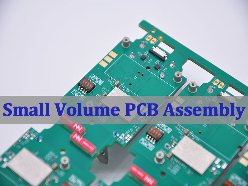
    Low volume PCB assembly manufacturer means a production partner that can reliably build prototype-to-small-batch PCBAs—often high-mix, fast-turn, and BOM-sensitive—without forcing “mass-production” constraints on early-stage hardware. This guide explains who low-volume assembly is for, what makes China and USA options different, how wholesale fits, and how to choose the best partner with fewer surprises.

    Why does low volume assembly feel simple on paper, but messy in practice?

    • Quotes swing wildly once component availability, alternates, and test requirements enter the picture.
    • Lead times slip because “in-stock” parts were not actually reserved when the order was placed.
    • First-build risk stays high when DFM/DFA feedback arrives late or is too generic.
    • Quality is inconsistent if inspection standards and acceptance criteria are not clearly defined up front.
    • Communication costs time when engineering questions bounce between sales, sourcing, and the SMT line.

    A capable manufacturer reduces this friction by turning it into a controlled process with clear checkpoints.

    • Transparent quoting that separates PCB fab, SMT labor, sourcing, and NRE so you can change one variable at a time.
    • Sourcing discipline (AVL alignment, alternates strategy, reservation windows) to protect schedule.

    • Front-loaded DFM/DFA with actionable comments before the first stencil is cut.
    • Defined quality targets (IPC class, inspection coverage, rework rules) that match your product risk.
    • Fast engineering communication with one owner who can close questions the same day.

    EBest Circuit (Best Technology) is a one-stop PCB & PCBA manufacturer focused on engineering-led execution for prototypes, low volume PCB assembly, and scale-up builds. We combine PCB fabrication, component sourcing, SMT/THT assembly, inspection, and functional test planning so early-stage teams can iterate faster while keeping quality stable. For more information or if you would like to send us any inquiry, please send us an email through the contact form at the bottom of our Contact Page.

    Low Volume PCB Assembly Manufacturer

    Top 5 Low Volume PCB Assembly Manufacturers

    Identifying a reliable partner is the first step. This section highlights five leading global manufacturers renowned for their excellence in low to mid-volume production, considering factors like technical capability, service range, and geographic reach.

    • PCBWay:​ A giant in the online manufacturing space, known for its user-friendly platform, instant quoting, and extensive community support. Ideal for hobbyists, startups, and engineers seeking a straightforward, cost-effective entry into low volume PCB assembly.
    • JLCPCB:​ Revolutionized the market with incredibly low-cost prototyping and assembly. Their strength lies in a massive inventory of basic components for their SMT assembly service, offering unbeatable speed and price for simple to moderately complex designs.
    • MacroFab:​ An excellent Low volume PCB assembly manufacturer USA​ option, operating a cloud-managed manufacturing platform. They provide a network of factories across North America, offering transparency, scalability, and strong supply chain management for clients wanting domestic production.
    • Sierra Circuits:​ Caters to the high-reliability and high-complexity end of the spectrum. While not the cheapest, they are a top choice for aerospace, medical, and military applications requiring stringent certifications (AS9100, ISO 13485) and advanced capabilities like RF and HDI PCB assembly.
    • EBest Circuit (Best Technology):​ Specializes in turnkey and technically challenging assemblies, with deep engineering support, proven expertise in medical PCBA and industrial control PCBA, and a long-term partnership approach for iterative product development.

    In summary, the best choice depends on your project’s priority: ultra-low cost (JLCPCB), platform ease (PCBWay), US-based flexibility (MacroFab), high-reliability (Sierra Circuits), or specialized engineering partnership (EBest Circuit).

    Low Volume PCB Assembly Manufacturer

    Why Engineers Choose A Low-Volume PCB Assembly Manufacturer For Early-Stage Projects?

    Early-stage hardware changes fast. The right low-volume partner is essentially a risk-reduction system that keeps iteration moving.

    Key reasons teams choose low-volume:

    • Iteration speed beats unit cost in early builds (faster learning → fewer redesign loops).
    • High-mix readiness: small batches often include multiple variants, ECOs, or firmware spins.
    • Controlled exposure: you validate mechanics, thermal, EMC, and usability before committing to volume.
    • Sourcing flexibility: a good low volume PCB assembly manufacturer can manage alternates without “silently swapping” parts.
    • Test evolution: you can start with boundary checks and expand to functional testing as the design stabilizes.
    • Better documentation habits: early builds force clean BOM/XY data, polarity, and revision control.

    Practical checkpoint table (what to lock down per build):

    Build StageMust-Have InputsOutput You Should Expect
    EVTBOM/XY + polarity + stack-up notesFirst-pass DFM/DFA + clean assembly
    DVTTest plan + acceptance criteriaRepeatable yields + stable rework rules
    PVTFinal AVL + packaging + labelingProduction-like flow with traceability

    Ultimately, low volume assembly is less about “small quantity” and more about “fast learning with disciplined controls.”

    How A China Low Volume PCB Assembly Manufacturer Balances Cost And Lead Time?

    A China low volume PCB assembly manufacturer typically wins on cost structure and supply-chain proximity, but lead time still depends on how well the project is prepared.

    What drives cost down (and when it doesn’t):

    • Component ecosystem proximity often reduces procurement overhead and substitutions.
    • Panel utilization and line changeover efficiency can make small runs economical.
    • Standardized processes (stencils, AOI programs, common packages) reduce NRE per build.
    • Shipping mode selection (express vs economy) can flip the “total lead time” outcome.

    What usually drives lead time up:

    • Long-tail parts (MCUs, connectors, power inductors)
    • Incomplete centroid/rotation or inconsistent refdes mapping
    • Unclear acceptance criteria for rework, cosmetics, and solder joints

    Decision table (fast, realistic planning):

    LeverImproves CostImproves Lead TimeBest Practice
    Consigned partsOftenSometimesConsign only the risk items you truly control
    Turnkey sourcingSometimesOftenUse an approved alternates list
    Standard finishesYesYesAvoid exotic options unless needed
    Clear DFM notesIndirectlyYesCall out polarity, thermal pads, press-fit rules

    In practice, China can be an excellent choice for low cost PCB assembly, but the schedule is won or lost on sourcing clarity and clean production data—not geography alone.

    What Makes China Low Volume PCB Assembly Manufacturers Competitive Globally?

    China low volume PCB assembly manufacturers compete well because they combine supply chain density with scalable manufacturing workflows.

    Competitive advantages you can actually feel in a project:

    • Broad component access and faster alternate sourcing cycles.
    • Mature turnkey models that integrate PCB fab + assembly + procurement (often “upload-to-order” flows).
    • High-mix operational experience from serving prototypes, maker programs, and startup pilots.
    • Scalability: many suppliers can move from 5 boards to 5,000 with fewer process changes than expected.
    • Process options: SMT + THT, AOI, X-ray for BGA/QFN, selective solder, and functional test integration (varies by vendor).

    A quick “fit check” list (use before you request a quote):

    • Can they support your package risk (BGA, 01005, fine-pitch QFN)?
    • Do they offer clear consigned vs turnkey terms?
    • Do they state inspection scope (AOI/X-ray/ICT/functional)?
    • Can they manage engineering questions quickly and in writing?

    In reality, the global edge comes from integrated sourcing + repeatable high-mix execution—especially when you are iterating fast.

    When A Wholesale Low Volume PCB Assembly Manufacturer Is The Right Choice?

    A wholesale low volume PCB assembly manufacturer makes sense when you have repeatable demand patterns and want pricing leverage without jumping to full mass production.

    Pick wholesale-style low volume assembly when:

    • You have multiple SKUs/variants sharing common processes.
    • You can forecast in rolling windows (even if it’s imperfect).
    • Your BOM is mostly stable, with alternates already approved.
    • You want batch pricing and simplified reorder cycles.
    • You’re trying to reduce per-build overhead (NRE, setup time, procurement cycles).

    Where wholesale helps most:

    ScenarioWhy Wholesale Fits
    Reorders every month/quarterLess re-setup and fewer “first build” questions
    Multi-SKU product familyShared stencil strategy and line programs
    Component risk managementBulk procurement reduces schedule shocks

    As a result, wholesale low-volume is the bridge between “prototype chaos” and “production discipline,” as long as your design and BOM have started to settle.

    Top 10 Low Volume PCB Assembly Manufacturer USA

    For projects requiring IP protection, strict regulatory oversight, or rapid physical collaboration, domestic US manufacturers are indispensable. This list highlights key players known for quality and service in low-volume production.

    • Sierra Circuits:​ The premier name for high-reliability, complex prototypes and production, especially in defense and aerospace.
    • MacroFab:​ A cloud platform that connects customers to a network of US-based factories, ideal for managing multiple projects and scaling from prototype to production.
    • Sunstone Circuits:​ Offers a full suite of low cost PCB manufacturing​ and assembly services with a strong focus on user experience and fast prototype turns.
    • PCB Universe:​ Specializes in quick-turn, low-to-mid volume assembly with strong engineering support and a wide range of capabilities.
    • Imagineering Inc.:​ A well-established provider known for reliable prototype and low volume assembly​ with a focus on military and commercial applications.
    • Royal Circuits:​ Excels in complex, high-layer-count PCBs and their assembly, serving advanced technology sectors.
    • Accu-Tronics:​ Provides full-turnkey assembly services with an emphasis on medical, aerospace, and industrial electronics.
    • Epec Engineered Technologies:​ Offers end-to-end services from design to box-build, with expertise in harsh-environment and demanding applications.
    • Axiom Electronics:​ Focuses on complex, high-mix assembly and is known for technical proficiency in BGA, micro BGA, and COB.
    • Screaming Circuits (Milwaukee Electronics): Specializes in ultra-fast prototype and low volume PCB assembly, offering builds from as few as one board with strong DFM support and consistent quality for time-critical programs.

    The US market offers deep expertise and security, with manufacturers catering to everything from simple prototypes to mission-critical systems, ensuring there is a partner for every need.

    What Separates The Best Low Volume PCB Assembly Manufacturer From The Rest?

    The Best low volume PCB assembly manufacturer is not defined by one feature. It’s defined by how consistently the supplier prevents hidden failure modes.

    Seven differentiators that matter in real builds:

    • DFM/DFA that is specific (not generic checklists).
    • BOM governance: alternates policy, traceability, and part reservation discipline.
    • Clear process windows for stencil, paste, reflow profiles, and moisture-sensitive parts.
    • Inspection strategy you can audit (AOI/X-ray/functional scope is explicit).
    • Rework standards that protect reliability (not just “make it pass”).
    • Revision control across Gerbers, BOM, XY, and assembly drawings.
    • A real escalation path when something is ambiguous or risky.

    Simple scoring table you can use:

    CategoryGreen FlagRed Flag
    Engineering Q&AQuestions closed within 24–48 hoursVague answers, no written trail
    SourcingAlternates pre-approvedSilent substitutions
    QualityAcceptance criteria agreed upfront“We’ll handle it” without standards

    In effect, the best partner behaves like an extension of your engineering team, not just a line that places parts.

    How Low Volume PCB Assembly Supports Faster Design Iteration?

    Low volume PCB assembly supports iteration by shortening the “design → build → learn” loop while keeping builds comparable across revisions.

    How iteration speed is actually achieved:

    • Build plans per revision (EVT/DVT/PVT mindset even if you don’t name it).
    • Standardized deliverables: BOM, centroid, fab notes, assembly notes, test notes.
    • Tighter feedback loops: early DFM comments prevent costly respins.
    • Faster ECO handling with controlled change logs and clear delta scope.
    • Yield tracking even for small runs so you know whether issues are random or systemic.

    A compact “iteration checklist” (use every time):

    • Freeze refdes and polarity marks
    • Lock package footprints and courtyard rules
    • Declare critical nets and impedance constraints
    • Define functional test minimums (even basic power-up checks)

    In this way, with a disciplined low-volume process, you iterate faster without degrading quality or losing track of what changed.

    Low Volume PCB Assembly Manufacturer

    All in all, low volume PCB assembly manufacturer is the practical path for turning early-stage designs into reliable, testable hardware—fast—without forcing you into mass-production assumptions too early.
    This article covered how to evaluate global and USA options, where China and wholesale models fit, and what separates the best suppliers from the average ones.
    EBest Circuit (Best Technology) supports prototype and low-volume PCBA with engineering-led DFM, sourcing control, and stable quality execution across builds. Pls feel free to reach out to start a conversation at sales@bestpcbs.com.

    You may also like

    What’s on a Circuit Board? A Clear, Practical Breakdown

    January 19th, 2026

    If you have ever opened an electronic device and looked at the green board inside, you may have wondered what all those tiny parts actually do. From smartphones and medical equipment to industrial controllers and home appliances, every electronic product relies on a circuit board to function properly.

    Understanding what’s on a circuit board helps you better grasp how electronics work, why certain designs are more reliable than others, and how problems are diagnosed when something fails.

    What is a Circuit Board?

    Before examining the mounted parts, it is important to recognize that the board itself is an engineered component.

    A PCB typically consists of an insulating substrate, most commonly FR-4 glass-reinforced epoxy, laminated with copper layers. These copper layers are patterned into traces that route signals and power between components. Additional features such as solder mask, silkscreen, and surface finish complete the structure.

    Key PCB elements include:

    • Copper traces for signal and power routing
    • Pads and vias to connect components and layers
    • Vias that connect different copper layers, especially for multilayer PCBs
    • Solder mask to prevent short circuits and protect copper
    • Silkscreen for reference designators, polarity marks, and assembly guidance

    The PCB defines how components are electrically connected and how heat and mechanical stress are managed.

    What is a Circuit Board?

    What’s on a Circuit Board and Why It Matters in Electronics?

    So, what’s on a circuit board? From an engineered perspective, a printed circuit board with electronics parts like LEDs, fuses, connectors, resistors, capacitors, ICs are considered as PCBA (PCB assembly product), while a PCB without any soldered components called bare PCB. And between them, PCB is one of a part of PCBA.

    There are two kinds of components used on a circuit board, passive components and active components. Passive components do not amplify signals or require control logic, but they shape voltage, current, timing, and stability. While active components control current flow and perform computation, amplification, or switching.

    The components are not placed randomly on a PCBA. Each one plays a specific role in controlling power, processing signals, storing data, or enabling communication with other systems.

    What’s on a Circuit Board and Why It Matters in Electronics?

    What’s on a Circuit Board?

    Passive Components on a Circuit Board

    Passive components form the electrical foundation of a circuit. Their main function is to shape and condition electrical energy by controlling current flow, stabilizing voltage, defining timing characteristics, filtering noise, and providing basic protection.

    The most common passive components on a circuit board include resistors, capacitors, inductors, transformers and so on. These components are typically small, highly reliable, and present in large quantities on most PCBs.

    ComponentReference DesignatorPrimary FunctionTypical PCB FormsCommon Schematic Symbol
    ResistorRLimits current, divides voltage, sets biasSMD, axial THT
    Capacitor (non-polarized)CCharge storage, decoupling, noise filteringCeramic SMD
    Capacitor (polarized)CBulk energy storage, smoothingElectrolytic, tantalum
    InductorLCurrent filtering, energy storagePower inductor, ferrite
    TransformerTVoltage conversion, isolationPower, signal transformer
    FuseFOver-current protectionSMD fuse, cartridge
    Thermistor (NTC / PTC)RT / THTemperature sensing, inrush limitingDisc, bead
    Varistor (MOV)RVSurge voltage suppressionDisc MOV

    Active Components on a Circuit Board

    Active components control current flow and can amplify, switch, regulate, or process signals. They require power to operate. The most common active components on a circuit board including ICs, diodes, transistors, amplifiers… ICs are the most complex parts on a circuit board. They include microcontrollers, processors, memory devices, analog front ends, and power management ICs. Their package types—such as QFN, QFP, or BGA—directly influence PCB layout density and assembly complexity.

    ComponentReference DesignatorPrimary FunctionTypical PCB FormsCommon Schematic Symbol
    DiodeDOne-way current flow, protectionSMD, axial
    Zener DiodeZDVoltage regulation, over-voltage clampSMD
    BJT Transistor (NPN/PNP)QAmplification, switchingSOT-23, TO-92
    MOSFET (N / P channel)QPower switching, controlSOT-23, TO-220
    Operational AmplifierU / ICSignal amplification, filteringSOIC, TSSOP
    Integrated Circuit (IC)U / ICLogic, processing, controlQFN, QFP, BGA
    Voltage RegulatorUStable voltage outputSOT-223, QFN
    OptocouplerU / OKSignal isolationSOP, DIP

    What Do Resistors Do on a Circuit Board?

    Resistors are among the most common components on a circuit board. Their primary role is to control the flow of electrical current. By limiting current, resistors protect sensitive components and help set correct operating conditions within a circuit.

    On most boards, resistors are used to:

    • Reduce voltage levels
    • Control current flowing into LEDs or IC pins
    • Create timing and biasing networks

    Resistors come in many values and sizes, especially in surface-mount designs. Although they are simple parts, incorrect resistor selection can cause overheating, unstable signals, or component damage.

    What Is the Role of Capacitors on a Circuit Board?

    Capacitors store and release electrical energy. On a circuit board, they are essential for maintaining stable voltage levels and reducing unwanted electrical noise.

    Capacitors are commonly used for:

    • Smoothing power supply fluctuations
    • Filtering high-frequency noise
    • Providing short bursts of energy when current demand suddenly increases

    You will often find capacitors placed very close to integrated circuits. This placement helps stabilize power delivery and prevents voltage dips that could cause malfunction or data errors.

    What Are Inductors and Coils Used for on a PCB?

    Inductors store energy in a magnetic field and resist changes in current. On a circuit board, they are mainly used in power management and signal filtering applications.

    Typical uses include:

    • DC-DC converters and voltage regulators
    • EMI suppression in power and signal lines
    • Filtering noise in radio-frequency circuits

    Inductors are especially important in designs where power efficiency and electromagnetic compatibility are critical, such as industrial controllers and communication equipment.

    What Are Integrated Circuits (ICs) on a Circuit Board?

    Integrated circuits, often called ICs or chips, are the most complex components on a circuit board. An IC can contain thousands or even millions of transistors inside a single package.

    ICs perform functions such as:

    • Processing data and executing software
    • Managing power distribution
    • Storing memory
    • Handling communication protocols

    The type of IC used determines much of the board’s functionality. Microcontrollers control system logic, memory chips store data, and power ICs regulate voltage and current. Because ICs are sensitive to heat and electrical stress, their placement and soldering quality are critical.

    What Are Integrated Circuits (ICs) on a Circuit Board?

    What Are Diodes, LEDs, and Transistors on a Circuit Board?

    Diodes allow current to flow in only one direction. They are commonly used for protection, rectification, and voltage regulation. LEDs are a special type of diode that emits light and is often used for status indication.

    Transistors act as electronic switches or amplifiers. They control large currents using small input signals and are fundamental to digital and analog circuits.

    Together, these components enable:

    • Signal switching and amplification
    • Protection against reverse polarity
    • Visual feedback through indicator lights

    Although small, these parts often determine how safely and efficiently a circuit operates.

    What Is the Bare Circuit Board Made Of?

    The circuit board itself is made from layered materials designed to provide mechanical strength and electrical insulation. The most common base material is FR-4, a fiberglass-reinforced epoxy laminate.

    A typical circuit board includes:

    • Copper layers for electrical connections
    • A solder mask to protect copper traces
    • Silkscreen markings for component identification

    Material selection affects heat resistance, signal integrity, and long-term reliability. High-performance applications may require specialized materials to handle higher temperatures or faster signal speeds.

    What’s the Difference Between PCB and PCBA?

    A PCB refers to the bare board without components installed. PCBA describes a board after all components have been mounted and soldered.

    This distinction is important because:

    • A PCB is only a foundation
    • A PCBA is a functional electronic assembly

    Many people use these terms interchangeably, but in manufacturing and sourcing, the difference affects cost, lead time, and quality control requirements.

    What’s the Difference Between PCB and PCBA?

    How Do All Circuit Board Components Work Together as a System?

    A circuit board functions as a coordinated system rather than a collection of isolated parts. Power enters the board through connectors, flows through regulators and filters, and reaches active components in a controlled manner. Signals move along copper traces, passing through resistors, capacitors, and ICs to perform specific tasks.

    Good circuit board design ensures:

    • Stable power distribution
    • Clean signal paths
    • Effective heat dissipation

    Poor design choices can lead to noise, overheating, or intermittent failures, even when high-quality components are used.

    FAQs

    1. What components are found on most circuit boards?

      Most circuit boards include resistors, capacitors, integrated circuits, diodes, connectors, and the board substrate itself. The exact mix depends on the application.

      2. Can you identify circuit board components by looking at them?

      Many components can be visually identified by shape and markings, but precise identification often requires a schematic or part number reference.

      3. What is the most important component on a circuit board?

      There is no single most important component. The board functions as a system, and each part contributes to overall performance and reliability.

      4. Are all circuit boards made of the same materials?

      No. While FR-4 is common, specialized boards use materials designed for high temperatures, high frequencies, or harsh environments.

      5. Why do some circuit boards have very few components?

      Highly integrated ICs can replace many discrete parts, allowing compact designs with fewer visible components.

      6. What’s the difference between through-hole and surface-mount components?

      Through-hole components use leads inserted into holes, while surface-mount components are soldered directly onto the board surface. Surface-mount designs allow higher component density and automated assembly.

      You may also like

      Common BGA Type Packages in PCB Electronics

      January 19th, 2026

      Ball Grid Array (BGA) packaging has become the backbone of modern electronics. From smartphones and laptops to automotive systems and medical devices, BGA packages enable higher performance, smaller form factors, and greater reliability. Understanding bga type packages, bga package sizes, and BGA package cross section is essential for PCB designers, hardware engineers, and sourcing teams who want to optimize performance while minimizing risk in manufacturing.

      In this guide, we break down everything you need to know about BGA packages—from structure and types to design challenges, assembly considerations, and real-world applications.

      What Is a BGA Package?

      A BGA package is a surface-mount integrated circuit package that uses an array of solder balls on the bottom side to form electrical and mechanical connections to the PCB. Instead of gull-wing or J-leads extending from the package edges, all interconnections are distributed underneath the device in a grid pattern.

      This bottom-side interconnection approach allows a much higher number of I/O connections within a smaller footprint, making the BGA type package particularly suitable for advanced digital, RF, and mixed-signal designs.

      What Is a BGA Package?

      Why Use BGA Chips on PCB?

      BGA packages are adopted not only for size reduction but also for performance and manufacturability reasons.

      Key advantages include:

      • Higher I/O density without increasing package outline.
      • Shorter signal paths, improving signal integrity at high speeds.
      • Lower inductance and resistance compared with leaded packages.
      • Improved thermal dissipation, especially for large silicon dies.
      • Better coplanarity control during reflow soldering.

      For multilayer PCBs with controlled impedance, dense routing, and fine-pitch BGAs, these benefits translate directly into higher electrical reliability and better long-term stability.

      Common BGA Type Packages in PCB electronics

      BGA Package Sizes Chart: Standard & Popular Sizes

      BGA package sizes are usually defined by three core parameters: package body size (in mm × mm), ball count and ball pitch (distance between centers of adjacent balls). Unlike QFP or SOP packages, pin count alone does not fully describe a BGA.

      Common BGA Package Body Sizes

      Package SizeTypical Applications
      5 × 5 mmSmall MCUs, IoT devices
      7 × 7 mmMobile peripherals
      10 × 10 mmConsumer electronics
      12 × 12 mmCommunication ICs
      15 × 15 mmSoCs, processors
      17 × 17 mmNetworking ICs
      23 × 23 mmHigh-end processors
      27 × 27 mm+GPUs, FPGAs, CPUs

      Typical Ball Pitch Options

      Ball PitchUsage
      1.27 mmLegacy BGAs, industrial
      1.0 mmStandard industrial BGAs
      0.8 mmConsumer electronics
      0.65 mmCompact designs
      0.5 mmSmartphones, tablets
      0.4 mm / 0.35 mmUltra-fine pitch, high-density

      Important:

      As ball pitch decreases, routing complexity, PCB cost, and assembly difficulty increase. Designs with 0.5 mm pitch and below usually require HDI PCB technology, microvias, and tighter process control.

      BGA Package Cross Section

      Understanding the BGA package cross section helps explain both electrical behavior and assembly challenges. Typical bga package cross section layers including:

      1. Silicon Die – The actual integrated circuit
      2. Die Attach Material – Bonds the die to the substrate
      3. Substrate (BT resin, ABF, etc.) – Routes signals from die to solder balls
      4. Bond Wires or Flip-Chip Bumps – Electrical connection between die and substrate
      5. Solder Mask Layer – Defines pad openings
      6. Solder Balls – External connections to PCB
      BGA Package Cross Section

      In a typical cross-section:

      • The silicon die is mounted on a substrate.
      • Wire bonds or flip-chip bumps connect the die to the substrate.
      • The organic substrate redistributes signals to the solder balls.
      • Solder balls form the interface between package and PCB pads.

      This layered structure supports high signal density while isolating mechanical stress between silicon and PCB materials.

      What Are the Different Types of BGA?

      Ball Grid Array (BGA) is not a single package format but a family of package structures optimized for different electrical, thermal, mechanical, and cost requirements. Understanding the different BGA type package variants is critical for PCB layout, stack-up planning, assembly process selection, and long-term reliability control. Common BGA type package families include:

      What Are the Different Types of BGA?

      1. PBGA (Plastic Ball Grid Array)

      PBGA uses an organic substrate with a wire-bonded die and plastic encapsulation. Typical ball pitch ranges from 1.27 mm to 0.65 mm, with ball counts commonly between 100 and 900 I/Os. It is the most widely adopted BGA package in high-volume electronics.

      Advantages

      • Low cost and mature supply chain
      • Compatible with standard SMT processes
      • Good balance of performance and manufacturability

      2. CBGA (Ceramic Ball Grid Array)

      CBGA is built on a multilayer ceramic substrate, offering higher thermal conductivity than organic materials. Ball pitch is usually 1.27 mm or larger, and package sizes often exceed 20 × 20 mm. It is designed for long-term reliability under thermal stress.

      Advantages

      • Excellent thermal stability
      • Minimal warpage across temperature cycles
      • Suitable for high-reliability applications

      3. FBGA (Fine-Pitch Ball Grid Array)

      FBGA is a compact BGA variant with reduced ball pitch, typically 0.8 mm, 0.65 mm, or 0.5 mm. It enables higher I/O density within a smaller footprint while maintaining acceptable electrical performance.

      Advantages

      • Smaller package size
      • Higher routing density
      • Well suited for HDI PCB designs

      4. FCBGA (Flip-Chip Ball Grid Array)

      In FCBGA, the silicon die is mounted face-down and connected to the substrate using micro bumps. This structure supports very high I/O counts (1,000+ balls) and excellent thermal paths from die to PCB.

      Advantages

      • Superior high-speed signal performance
      • Excellent heat dissipation
      • Ideal for high-power and high-frequency devices

      5. TBGA (Tape Ball Grid Array)

      TBGA uses a flexible polyimide tape as the substrate, resulting in a thinner and lighter package. Ball pitch typically ranges from 0.8 mm to 1.27 mm, with moderate I/O density.

      Advantages

      • Thin and lightweight structure
      • Reduced mechanical stress
      • Suitable for space-limited designs

      6. PoP BGA (Package on Package)

      PoP integrates two BGA packages stacked vertically, commonly logic on the bottom and memory on top. It reduces PCB area while maintaining short interconnect lengths between stacked components.

      Advantages

      • Significant PCB space savings
      • Improved signal integrity between logic and memory
      • Flexible memory configuration

      7. Micro BGA (µBGA)

      Micro BGA refers to ultra-small BGAs with ball pitch typically ≤0.5 mm and very compact outlines. These packages are optimized for extreme miniaturization and high-density interconnections.

      Advantages

      • Maximum size reduction
      • High electrical performance in small form factors
      • Ideal for advanced HDI and microvia PCBs

      Each type places different demands on PCB stack-up design, solder mask strategy, and assembly process control.

      How Does BGA Compare to Other Packages?

      When compared with QFP, SOP, or QFN packages, BGAs offer a clear advantage in I/O scalability and signal performance.

      FeatureBGAQFPQFNLGA
      I/O DensityVery highMediumMediumHigh
      FootprintSmallLargeSmallSmall
      Routing ComplexityHighLowMediumHigh
      Assembly DifficultyHighLowMediumMedium
      ReworkabilityDifficultEasyMediumMedium

      However, BGAs require more advanced PCB fabrication and assembly capabilities, particularly for inspection, rework, and thermal profiling.

      What Is the Difference Between LGA and BGA Packaging?

      The key distinction lies in how the electrical connection is formed.

      • BGA: Uses solder balls attached to the package; soldering occurs during PCB assembly.
      • LGA: Uses flat pads on the package; solder or contact springs are on the PCB side.

      BGA packages generally offer stronger mechanical joints after reflow, while LGA packaging can simplify rework and reduce package height in some applications.

      Is BGA Used in Mobile Phones?

      Yes. BGA and its derivatives are extensively used in smartphones and mobile devices.

      Typical mobile BGA applications include:

      • Application processors
      • Memory devices (eMMC, LPDDR)
      • RF baseband and connectivity chips

      Ultra-fine pitch BGAs and PoP structures are especially common, supporting compact layouts while maintaining high data throughput.

      Common Uses of BGA Package

      The bga type package is found across a wide range of industries and applications, including:

      • Consumer electronics and smart devices
      • Networking and data communication equipment
      • Industrial control systems
      • Automotive electronics
      • Medical and diagnostic equipment
      • High-performance computing and servers

      As PCB designs continue to push toward higher speed, smaller size, and greater integration, BGA packaging remains one of the most adaptable and future-proof interconnection solutions.

      Why BGA Expertise Matters in PCB Assembly?

      Not all PCBA manufacturers are equal when it comes to BGA. Fine-pitch BGA, microBGA, and flip-chip BGA require advanced capability, experience, and strict process control.

      Our BGA Assembly Capabilities Include:

      • 0.4 mm / 0.5 mm fine-pitch BGA assembly
      • HDI PCB manufacturing with microvias & via-in-pad
      • Advanced X-ray inspection for 100% BGA verification
      • Precise reflow profile control
      • BGA rework and repair services
      • DFM analysis to reduce risk and cost
      • IPC Class 2 & Class 3 assembly support

      Why Choose Us for BGA PCB Assembly?

      With years of experience in high-density and high-reliability electronics, we support customers across consumer, industrial, automotive, and medical sectors.

      We provide:

      • One-stop PCB fabrication + assembly
      • Dedicated engineering support
      • Strict quality control and traceability
      • Competitive pricing with no compromise on reliability
      • Fast turnaround for prototypes and volume production

      Looking for a reliable partner experienced in all BGA type packages?
      Contact us today for a free DFM review and professional support on your next BGA PCB project.

      FAQ

      1. Are BGA packages hard to repair?

      Yes. BGA rework requires specialized equipment and skilled technicians.

      2. What is the smallest BGA package size?

      microBGA and WLCSP packages can be under 3 × 3 mm.

      3. Can BGA be hand-soldered?

      No. BGA packages require reflow soldering.

      4. Is BGA more reliable than QFN?

      For high pin count and high-speed applications, yes—when properly designed and assembled.

      You may also like

      NPN vs PNP Transistor​: What’s the Difference?

      January 16th, 2026

      The comparison npn vs pnp transistor is fundamental to understanding how bipolar junction transistors (BJTs) behave in real electronic circuits. Although NPN and PNP transistors serve the same basic function—using a small control current to regulate a larger current—their internal structure, biasing logic, current direction, and application scenarios differ in important ways.

      These differences directly affect schematic design, component selection, PCB layout, grounding strategy, and even system-level safety behavior. Engineers who clearly understand npn vs pnp can make cleaner designs, avoid common wiring mistakes, and improve long-term reliability in both analog and digital systems.

      NPN vs PNP Transistor​: What’s the Difference?

      What Is an NPN Transistor?

      An NPN transistor is a type of bipolar junction transistor made from three semiconductor regions arranged as N-type emitter, P-type base, and N-type collector. The name “NPN” reflects this physical structure.

      In an NPN transistor:

      • Electrons are the majority charge carriers
      • The emitter is heavily doped to inject electrons
      • The base is thin and lightly doped
      • The collector collects electrons flowing through the device

      Because electrons move faster than holes, NPN transistors generally offer better switching speed and higher gain compared to PNP devices. This is one key reason NPN transistors dominate modern electronic designs.

      How Does a NPN Transistor Work?

      An NPN transistor operates by forward-biasing the base–emitter junction. When the base voltage is raised approximately 0.7 V above the emitter (for silicon devices), electrons begin to flow from the emitter into the base.

      Most of these electrons do not recombine in the base. Instead, they are pulled into the collector by the collector–base electric field. As a result:

      • A small base current controls
      • A much larger collector current

      This behavior allows the NPN transistor to function as:

      • A current amplifier
      • A digital switch

      In PCB applications, NPN transistors are most commonly used as low-side switches, where the load connects to the supply voltage and the transistor completes the path to ground.

      How Does a NPN Transistor Work?

      Advantages and Limitations of NPN

      Advantages of NPN Transistors

      • Faster switching due to electron mobility
      • Simple biasing with ground-referenced logic
      • Excellent compatibility with microcontrollers and digital ICs
      • Wide availability in signal, power, and RF variants
      • Lower cost in most voltage and current ratings

      Limitations of NPN Transistors

      • Not ideal for high-side switching without level shifting
      • Ground noise can affect sensitive analog stages
      • Load remains connected to supply when transistor is off

      What Is a PNP Transistor?

      A PNP transistor is also a bipolar junction transistor, but its internal structure is reversed: P-type emitter, N-type base, and P-type collector.

      In a PNP transistor:

      • Holes are the majority charge carriers
      • Current flows from emitter to collector
      • Control logic is inverted compared to NPN

      PNP transistors are commonly used when the design requires switching or controlling current on the positive side of the power supply.

      How Does a PNP Transistor Work?

      A PNP transistor turns on when the base voltage is lower than the emitter voltage by about 0.7 V. This forward-biases the base–emitter junction and allows holes to move from the emitter into the base.

      Once active:

      • Holes continue into the collector
      • Current flows from emitter → collector → load

      Because of this current direction, PNP transistors are well suited for high-side switching, where the transistor supplies current from the power rail to the load.

      How Does a PNP Transistor Work?

      Advantages and Limitations of PNP

      Advantages of PNP Transistors

      • Natural solution for high-side switching
      • Useful in power distribution and sourcing circuits
      • Allows loads to be fully disconnected from supply
      • Common in automotive and industrial controls

      Limitations of PNP Transistors

      • Slower switching due to hole mobility
      • Less intuitive control logic for beginners
      • Harder to interface directly with low-voltage logic
      • Often requires pull-down or level-shifting circuits

      NPN vs PNP Symbol: How to Identify Them?

      The transistor symbol provides a clear visual clue:

      • NPN transistor: emitter arrow points outward
      • PNP transistor: emitter arrow points inward

      A commonly used memory aid is:

      “NPN: Not Pointing iN.”

      NPN vs PNP Symbol: How to Identify Them?

      Correctly identifying transistor symbols is critical during schematic review and PCB footprint validation, especially when layouts are shared across teams.

      Why Would You Use a PNP Transistor?

      You would choose a PNP transistor when the design requires:

      • Switching on the positive supply rail
      • A default-off load when control signal is inactive
      • Current sourcing rather than sinking
      • Simplified high-side power control

      PNP transistors are frequently used in:

      • Automotive electronics
      • Industrial automation
      • Power monitoring circuits
      • Sensor supply control

      Key Differences Between NPN and PNP Transistors

      AspectNPN TransistorPNP Transistor
      Semiconductor structureN-P-NP-N-P
      Majority carriersElectronsHoles
      Turn-on conditionBase higher than emitterBase lower than emitter
      Current flowCollector → EmitterEmitter → Collector
      Typical roleLow-side switchHigh-side switch
      Logic compatibilityExcellentMore complex

      When to Use NPN vs PNP Transistors?

      Choosing npn vs pnp depends on system architecture and control logic:

      • Use NPN when working with microcontrollers, logic ICs, or ground-referenced signals
      • Use PNP when switching loads from the positive rail
      • Consider PCB grounding, noise paths, and return currents
      • Evaluate system behavior during power-up and fault conditions

      In advanced designs, NPN and PNP transistors are often paired in complementary stages to achieve push-pull outputs, level shifting, or bidirectional drive.

      FAQs

      1. Is an NPN transistor better than a PNP transistor?

      Neither is universally better. NPN is more common, while PNP excels in high-side control.

      2. Can NPN and PNP transistors be used together?

      Yes. Many amplifiers and drivers rely on complementary NPN/PNP pairs.

      3. Why are NPN transistors used more often?

      They switch faster, cost less, and interface easily with logic circuits.

      4. How do I identify NPN vs PNP on a PCB?

      Check the schematic symbol, component marking, or datasheet pinout.

      5. Can I directly replace a PNP with an NPN transistor?

      No. Their biasing and current directions differ and require redesign.

      You may also like