PCB manufacturing PCB manufacturing
Home > Blog

What is flying probe test printed circuit boards?

June 16th, 2021

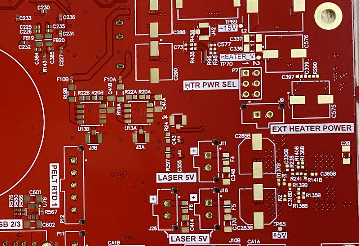
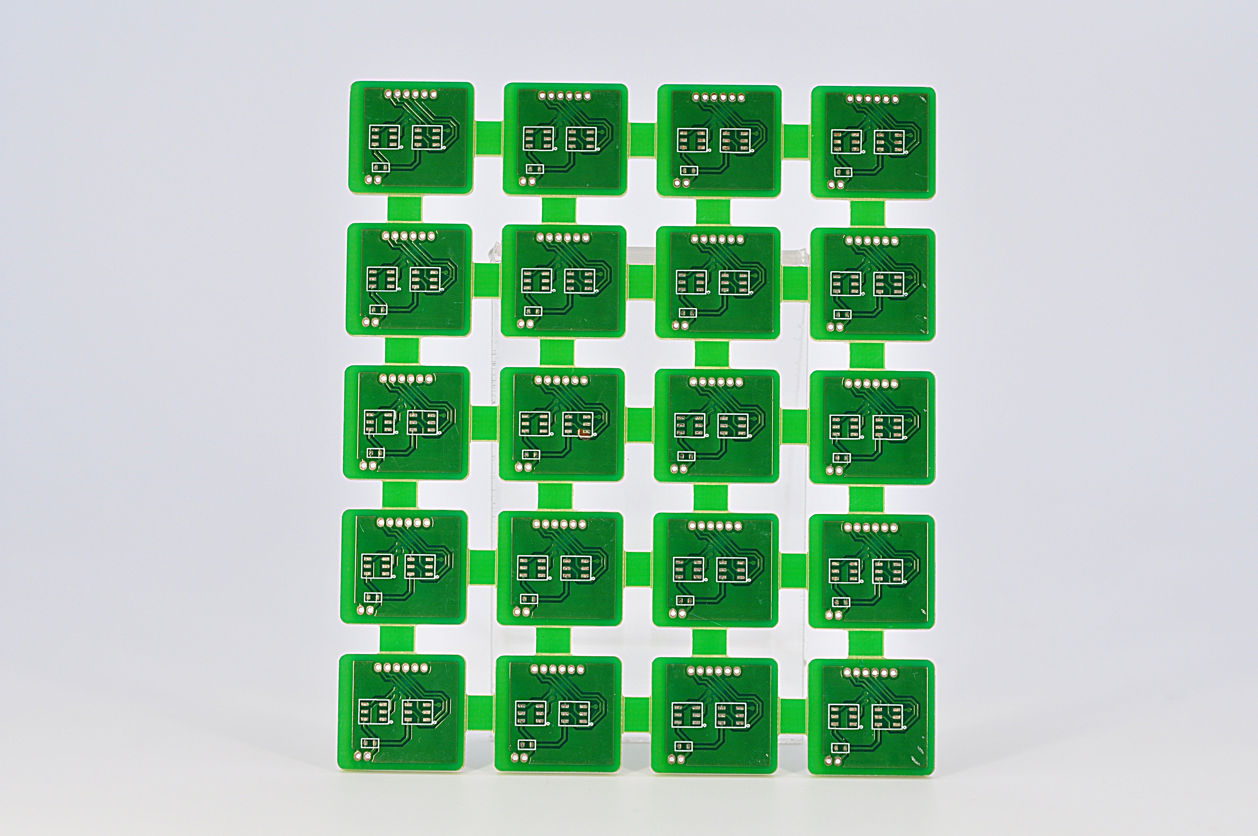
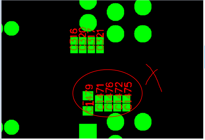
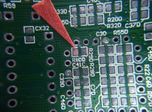
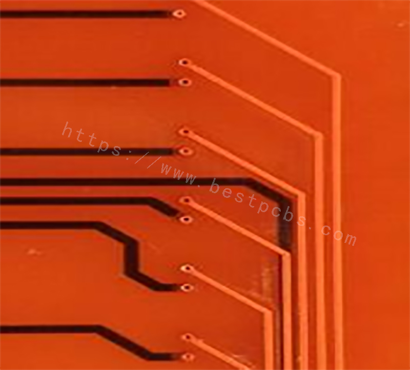
Before leaving PCB manufacturing line, bare PCBs (Printed Circuit Boards) have to pass electrical tests so that it guarantee that boards go for high performance and high reliability after finish the SMT(Surface Mount Technology). Electrical tests are implemented to find out electrical and circuitry issues such as shorts, opens, resistance, capacitance etc. all of which indicate whether bare boards or assembled board are correctly fabricated.

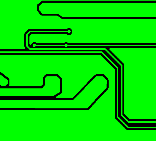
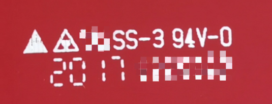
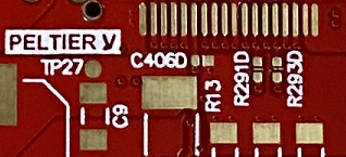
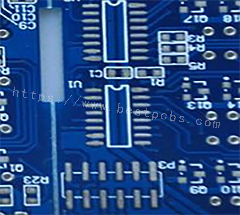
shorts circuit

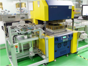
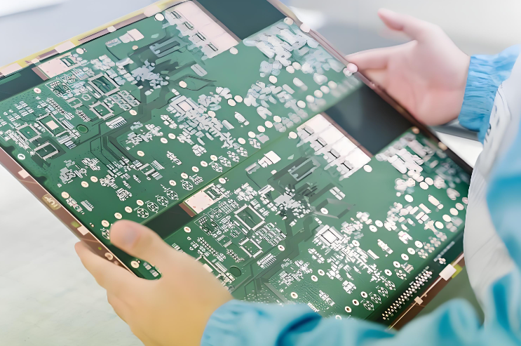
When test probes work, it moves quickly from test points to other test points as per instructions instructed by the computer set up program.  

probe flying test

Probe test is no need fixture, so it is very popular in the printed circuit boards manufacturing. The most significant reason is their cost. it is highly cost-effective for prototypes and low to mid-volume production. And the most important factor, the test reports can be provided for each board after finish tested and it is very easy to export from the computer, you can send to your customer very quickly for the test results of PCB.

Advantages of Flying Probe Test:

Low test cost (Eliminates fixturing costs and time)

Short test development time

Fast computer program development, easy integration of design changes

Rapid feedback provided to PCB design engineers at prototyping period

Process flexibility

Circuit access, even in the absence of test points

Controlled probe contact, programmable for any type of board

Different test solutions and approaches integrated in a single test system

Intrinsic positioning and measurement precision

Disadvantages of Flying Probe Test

Everything has two sides. Apart from obvious advantages, flying probe test have some disadvantages.

Since flying probes have direct physical contact with vias and test pads and small pits are easily caused on board surface, when flying probe tester is working on components without test pad, it’s possible that probes have contact with component leads so that loose leads or leads with badly-performed soldering may be missed.

In spite of the disadvantages mentioned, flying probe test is still regarded as a significant test method for PCB fabrication. Flying Probes have enhanced the competitive variable as lost time due to retooling has been removed. Prototype and Quick Turn product is the perfect match for Flying Probes as they carry out in low quantity orders and are quick to change jobs, unlike the long setup times with fixture testers.

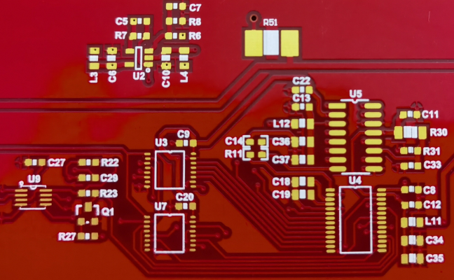
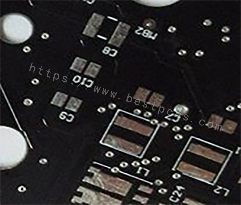
By the way, to test circuit shorts, opens, EBest Circuit (Best Technology) also do AOI checking to make sure there is no issue for PCB manufacturing.

AOI test

Contact EBest Circuit (Best Technology) right now, to discuss more for printed circuit boards.

You may also like

How to do SMT for ceramic PCB

May 19th, 2021

As we all know if ceramic PCB is very fragile, so it is not easy to do SMT for them.

But we can do the SMT for ceramic PCB easily because we do it every day and we have more than 15 years experiences for doing that.

For the almost SMD components (such as SMD rsistors, capacitors, diode etc), normally we will add the solder paste by using SMT stencil, then put the components by machine, finally do the oven reflow.

For some special components, we will need to solder it by hand, such as through connectors, but it can’t be soldered by hand directly, it need to be put on the heating table to keep the temperature is high enough to make the solder past at melt state. Because the ceramic material with very good heat dissipation, the solder paste will be solidification very easily if don’t put the ceramic PCB on heating table

For some small LED, it can’t be put by SMT machine, because no such small feeder to pick it up, then need to put it on board by hand.

We can do very well for the small BGA components too.

Below some photos of ceramic PCB.

If you would like to know more about ceramic and ceramic PCB SMT, please feel free to email me

Ceramic PCB with SMT 1
Ceramic PCB with SMT 2
Ceramic PCB with SMT 3
Ceramic PCB with SMT 4
Ceramic PCB with SMT 5

You may also like

Aluminum vs Copper Core PCB

May 19th, 2021

In EBest Circuit (Best Technology), currently the most common metal used for Metal Core PCB manufacturer are Aluminum, Copper. Today let’s talk about the main differences between aluminum substrate and copper substrate, hoping to help you choose the right substrate in future design projects.

Although they both share similar properties and functions, there are still a few variations between the two kinds of metals. Some of the key differences between aluminium and copper core PCBs are explained in the points below.

1. Thermal Conductivity

The thermal conductivity of copper substrate is up to about 400(W/mK) and the thermal conductivity of aluminum substrate is generally about 200W(W/mK). The thermal conductivity is higher, the transfer efficiency will be better, and the heat dissipation will be better, then the working life will be longer.

 Thermal Conductivity

2. Electrical Conductivity

Both aluminum and copper, being metals, are electrical conductors of electricity, although the exact degree of this varies between the two metals. When it comes to electrical conductivity, copper has a clear advantage over aluminum. In other words, in applications where there is a need for efficient electrical conductivity, copper makes for an ideal pick.

 Electrical Conductivity

3. Electrical Resistance

Resistance is very important when it comes to PCB design, as it can have an effect on the overall function and stability of the component. Given that copper has a higher density than aluminum, it tends to have a lower resistance than aluminum, so copper is an better choice where there’s a requirement for thinner circuits and faster electricity transfer.

Electrical Resistance

4. Weight

Since copper has the higher density for per unit area, the weight of copper PCB is much heavier than aluminum PCB for the same design.

In applications where light-weight construction is required more than anything else, aluminum is the preferred material of choice. On the other hand, applications where weight is not much of an issue, tends to be the ones where copper is widely used.

Weight

5. Application

Copper core PCB is the best heat dissipation among all MCPCB, so it’s mostly used in automobile headlights, taillights and some high-tech electronic products (unmanned aircraft, mining machine) high-power lighting equipment. The aluminum core PCB is mostly used in indoor lighting, energy saving lighting, street lighting and other energy-saving lighting electronic products.

Application
Application

In conclusion, due to the above different parameters and performance, the cost of copper is generally more expensive than aluminum. If you have other questions about MCPCB, welcome to contact us .

You may also like

How to Test for an Open Short Circuit on a PCB?

May 18th, 2021

Every printed circuit board need to do full test before ship to our customer. but you may have doubt, the PCB was made according to the original Gerber file, why finish the PCB production process, why the short Circuit will occur on a FR4 circuit board?

A short circuit may also occur during reflow soldering. the solder paste may accidentally connect two pins that are very close to each other. In some cases, errors can occur during the PCB design process because the wiring between different networks accidentally connects.

We believe every PCB manufacture have their own test method to do short circuit, but today I would like share how EBest Circuit (Best Technology) to Check for Short Circuits in a Printed circuit board.

Here are some important steps:

Step 1 Visual inspection

The first step for locating short circuits on PCB is to carefully look at the entire surface of the PCB. EBest Circuit (Best Technology) QC guys use a magnifying glass or low magnification microscope during the circuit board examination. We check the whole board surface to see if there are some traces break off. Any cracks or blobs of solder should get careful attention. Check all your vias. If you specified unplated vias, make sure that’s the case on the board. Poorly plated vias can create a short circuit between layers and leave you with everything tied to ground, VCC, or both.

visual inspection

All the testing work will carry out according to IPC 6012 class 2.

Step 2 Use a Digital Multimeter to find out where is the problem

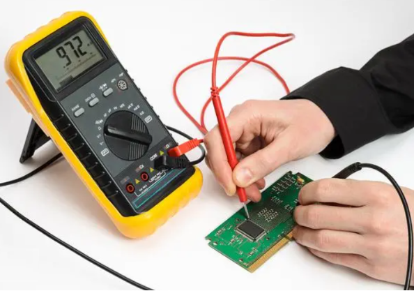
To test a circuit board for a short circuit, you need to check the resistance between different points in the circuit. If visual inspection doesn’t reveal any clues as to the location or cause of the short circuit, grab a multimeter and try to track down the physical location on the printed circuit board. The multimeter approach gets mixed reviews in most electronics forums, but tracing your test points can help you figure out what isn’t the problem.

Step 3 use Probe flying Tester &E-tester

As long as you are in Printed Circuit board field, you are definitely known Probe flying test and E-Teter.

Flying probe test systems require no test fixture, it can serve both prototype and small production, providing maximum flexibility for PCB manufacturers and this job can complete in a short time.

probe flying test
probe flying test-1

But when your circuit board become to volume, you will need to open a test tooling/test fixture to test the Printed Circuit board to test the open short circuit.

E-tester

In my next blog in June, I will introduce Probe flying test to you in more detail.

If you have any question about printed circuit board, you are welcome to contact EBest Circuit (Best Technology).

It is our great pleasure to communicate with you for any issue for printed circuit boards.

You may also like

What’s the differences between thick film ceramic PCB and DPC ceramic PCB

April 21st, 2021

Ceramic PCB including Alumina PCB (Al2O3 PCB), Aluminum Nitride PCB (AlN), Bryllium Oxide PCB(BeO PCB) etc.

There are other differences except the substrate material is different.

  1. The method of making conductor is different.

The conductor for thick film ceramic is made by printing, but DPC is made by vacuum sputtering and plating.

  • The conductor is different.

The conductor for thick film ceramic PCB is Au or AgPd, but for DPC ceramic PCB, it is copper.

  • The thickness of conductor is different.

Normally, it is 10-20um for thick film ceramic PCB, copper thickness can be 10um-300um for DPC ceramic PCB.

  • The solder mask is different.

It is glass glaze for thick film ceramic PCB, the most popular color is greenish and blue. Glass glaze can withstand very high temperature, up to 850C

It is normal solder mask oil for DPC ceramic PCB, the most popular color is white.

The above is only simple introduction for the difference, if you want to know more differences between thick film ceramic PCB and DPC ceramic PCB or other details about ceramic PCB, please contact us

You may also like

What is Blind Via and Buried Via for Printed Circuit Board?

April 15th, 2021

In the Printed Circuit Board industry, believe that you are familiar with blind via and buried via. What is blind via and buried via for PCB? And do you know is the Blind via or Buried Via have special application in your Printed Circuit Board?

In order to know more, we would like to share more information with you today.

EBest Circuit (Best Technology) is an experienced FR4 PCB manufacturer in China since year 2006, with more than 15 years design and fabricate experience for PCB, EBest Circuit (Best Technology) accumulated more than 1000 customers from all over the world.

Before start, we need to know what kinds of hole for FR4 Circuit Board, Via, Blind Via and Buried Via.

What is a Via?

Vias are the copper-plated holes in the PCB that allows the layers to layer connection. The standard via is called a through-hole via, but there are several disadvantages to using through-hole vias in Surface Mount Technology (SMT). For this reason, we often use a blind via or buried via instead. A blind or buried via can be processed in a wide range of different measures, including plugged copper mask via, a plugged solder mask via, plated via or staggered via.

Via
staggered via

What is Blind Via?

The via connects the external layer to one or more inner layers of the PCB and is responsible for the interconnection between that top layer and the inner layers.

Blind Via

What is Buried Via?

For a buried via, is the inner HOLE, between both sides in the board up and down inside the layer after pressing is cannot see. So, it doesn’t have to take up the outer area.

Buried Via

Blind and buried vias are particularly advantageous in HDI board because they optimize the density of the boards without increasing board size or the number of board layers you require. They are most commonly used in high-density PCB designs like, or in FPGA and custom chip packaging.Here is the photo which EBest Circuit (Best Technology) took from our production line to make HDI Printed Circuit Board for our USA customer.

HDI board under production
HDI process

EBest Circuit (Best Technology) is a very professional manufacturer in printed circuit board and HDI Board. If you are interesting to know more information of us, come to contact us and we are looking forward to discuss with you more for Printed Circuit Board.

You may also like

Interesting color matching – Silkscreen and Solder mask

March 23rd, 2021

In EBest Circuit (Best Technology), solder mask and silkscreen are available in a variety of colors. For example, common colors of solder mask are black, white, blue, green, red. Common silkscreen colors are black, white, yellow, red, blue. Generally according to the different needs of customers to use collocation, but sometimes if the color collocation is not appropriate will produce color difference.

The following is a list of common collocations that we recommend based on our experience for your future project design.

Solder maskRecommended Silkscreen
BlackWhite
WhiteBlack/Blue/Green/Red/Yellow
BlueWhite
GreenWhite
RedWhite

For the most part,the color of solder mask doesn’t have any effect on PCB’s

functionality.But if the color of the silk screen does not match properly,which may

Cause chromatic aberration(for example,a yellow silkscreen on a black solder mask,

The silkscreen visual may look green)or make reading the silk screen more difficult

To read(for example, a black silkscreen on a light black solder mask).The solder mask will also affect your ability to visually inspect the PCBs. Below are the solder mask comparison from the highest contrast to the lowest for your reference.

Green

Most customers will choose to use Green solder mask for their project since Green is easy on the eyes and allows for high contrast between traces, planes, and empty space on the PCB. Green solder mask has become an industry standard. High contrast allows technicians to most easily review for manufacturing defects.

green

Red

A Red solder mask will provide a bold and clean looking PCB, however the contrast between traces, planes, and empty space significantly lower than it is with a green solder mask. Magnification may be needed when inspecting fine traces on the board for defects with a Red mask. White silkscreen will be better than black silkscreen on a board with red solder mask.

red

 Blue

Blue solder masks have even lower contrast, and magnification becomes required when inspecting for manufacturing defects. These PCBs look visually pleasing and professional and are a good choice for fully-developed products that will not require trace visibility.

blue

Black

Black masks have almost no contrast between traces, planes and empty space. A Black mask will absorb heat, increasing the danger of overheating for sensitive components. Pay attention that in order to avoid the appearance of color difference as far as possible do not choose the silkscreen like yellow, green, red, or blue. White will be the better choice.

black

White

A white mask will be the hardest to clean, and also has the lowest contrast. If possible, we suggest that you avoid choosing white, especially in the prototyping stage. It’s the best choice to use white solder mask for LED board, following pictures for your reference.

whtite

If you have other questions about solder mask, welcome to contact us. (Email:sales@bestpcbs.com), we will prove you professional suggestions and solutions.

You may also like

The Advantages of Surface Mount Technology of a printed circuit board

March 19th, 2021

Surface-Mount Technology has been the industry standard for assembling printed circuit board. It has maintained its popular due its wide array of advantages and relatively few drawbacks. For more than 15 years’ experience, EBest Circuit (Best Technology) has been offering surface-mount service for worldwide customers, and SMT service become a great part of our business.

See some photo which we are do assembly for our customer this month.

SMT 1

Top Advantages of Surface-Mount Technology

Smaller size and reduced weight are the two main advantages to SMT. Components can be aligned closer together and end products will be more compact and light weight.

SMT 2

Here are additional benefits of SMT:

1.Component placement auto correctly â€“ there is no alignment between the PCB solder pads and components pads to avoid placement errors.

2.Low cost:

The advantage of small size up to 0201. One set, SMT typically requires lower production costs than through-hole placement. The size of the board is reduced, the number of drilled holes is reduced, and routing of traces is reduced. So bring down the cost of the whole project.

3.Design flexibility â€“ You can combine through-hole technology and SMT manufacturing on the same board for greater functionality.

4. Printed circuit boards created with the SMT process are more compact, providing higher circuit speeds. (This is the main reasons most manufacturers choose for this method.)

5.Higher circuit speeds â€“ Most manufacturers rate this the number-one benefit.

Lower resistance/induction â€“ High-frequency performance reduces unwanted consequences of RF signals.

6. Quick Turn Around

Using Surface-Mount Technology, it can save lots of time, SMT is a much more streamlined manufacturing process compared to through-hole. Time is saved because components are applied using a solder paste instead of drilling holes in the PCB

7. Quantity â€“ More components can be positioned using both sides of the circuit board, creating more connections for each component. Fewer circuit boards are needed for devices.

8. Stability â€“ Better performance delivery is realized with vibration mechanical conditions. SMT connections are more reliable, it can reduce the dis connection risks during the final test.

SMT 3

EBest Circuit (Best Technology) offers expert surface-mount technology services in China, along with manufacturing bare printed circuit board, flexible circuits, and MCPCB fabrication. With more than 15 years rigid PCB board experience, EBest Circuit (Best Technology) has the resources, equipment, and know-how to produce your PCBs quickly and reliably.

different assembled board photo

Call EBest Circuit (Best Technology) now and let us become your partner of PCB assembly service.

You may also like

Do the vias can be filled for ceramic PCB?

November 13th, 2020

As everyone knows for FR4 PCB, people like the vias to be tented or filled for some special applications.
Ceramic PCB is more and more popular because of the thermal conductivity is very high and very good for heat dissipation. Most of customers are going to make the PCB with ceramic material, includes Al2O3, AlN, BeO or Si3N4, etc.
So do the vias can be filled for ceramic PCB becomes the frequently asked questions (FAQ).
The answer is YES.
So what’s the material can be filled in vias for DBC/DPC alumina PCB/ Aluminium Nitride PCB?

The material can be solder mask, Dow Corning 1-4173 and copper/Cu.
Normally, customers want the vias/holes to be filled with copper.
Because copper can fill the vias very well and it is easier to do and it looks very good. Please see below photo.
The left one with filling with copper, the right one without filling copper

Why you need to fill the vias with copper?
1.Becuase if let the vias open, they will allow solder to flow through to opposite side of PCB during reflow, this causes bridging under components.
Filling the open vias/holes with copper can prevent from the solder pates into the vias.
2.If you need to pull vacuum around them and a hole would compromise that, so need to fill the vias.
There are also other purposes for filling the vias, if you need such ceramic board with filling the vias, please contact Coco in EBest Circuit (Best Technology) sales@bestpcbs.com

You may also like

What are the commonly used aluminum base materials? What’s the difference?

November 11th, 2020

EBest Circuit (Best Technology) has more than 14 year experience for producing Metal core PCB, we have our own raw materials factory for MCPCB and we fabricate MCPCB in Shenzhen, so that customer various special requirements can be meet here.

Compared to copper and stainless steel, aluminum is the most economic option considering thermal conductivity, rigidness, and cost. And many of these aluminum alloys base have been divided into classes, the commonly used on MCPCB are AL1060, AL3003, AL5052 and AL6061.

Do you know the differences between these substrates? This blog will give a brief introduction for you.

1060 alloys
AL1060 are commercially pure, unalloyed aluminum, it’s soft, ductile, workability and exceptional corrosion resistance, making it suitable for hard-forming applications. It can be welded with any method, but it cannot be heat-treated. Its cost is the lowest of the four types.

3003 alloys
AL3003 use silicon, copper, and magnesium as the main alloying elements, oftentimes with supplemental nickel and beryllium. They are heat treatable, have high strength, good resistance to cracking and wear, and have good machinability.

Mechanical PropertiesMetricEnglish
Ultimate Tensile Strength200 MPa29000 psi
Tensile Yield Strength186MPac
Shear Strength 110 MPa16000 psi
Modulus of Elasticity68.9GPa10000 ksi
Shear Modulus25 GPa3630 ksi

5052 alloys
AL5052 use magnesium as their primary alloying element and are not heat-treatable, but it’s the highest strength alloy of the more non-heat-treatable grades. Its resistance to fatigue is better than most grades of aluminum and have a great surface aesthetic when anodized.
In our company, if not special request or notes, the default material we use is AL5052 after considering all the performance and cost.

Mechanical PropertiesMetricEnglish
Ultimate Tensile Strength228 MPa33000 psipsi
Tensile Yield Strength193 MPa28000psi
Shear Strength138 MPa20000 psi
Modulus of Elasticity70.3GPa10200 ksi
GPaShear Modulus 25.9 GPa25.9 760 ksi


6061 alloys

Mechanical PropertiesMetricEnglish
Ultimate Tensile Strength310 MPa45000 psi
Tensile Yield Strength276 MPa40000 psi
Fatigue Strength207MPa30000 psi
Shear Strength96.5MPa14000 ksi
Modulus of Elasticity68.9 GPa10000 ksi
Shear Modulus26 GPa770 ksi

AL6061 implement magnesium with silicon as their principal alloying elements. Their strength is improved with heat treatment. AL6061 is one of the most widely used aluminum alloys, it has high strength and superior corrosion resistance. Its weld-ability and formability make it suitable for many general-purpose applications.

Cost Comparison: AL1060 < AL3003 < AL5052 < AL6061

If you have other questions about MCPCB, welcome to contact Tammy (Email:sales@bestpcbs.com), she will prove you professional suggestions and solutions.

You may also like