PCB manufacturing PCB manufacturing
Home > Blog

Solder paste

What Causes Solder Graping and How Can You Prevent It?
Friday, October 23rd, 2026

Solder graping is incomplete coalescence of solder powder, leaving a cluster of recognizable particles on a reflowed solder deposit. Small SMT paste deposits are especially vulnerable when exposed particles oxidize before the remaining flux can clean and protect them. The practical response is to check deposit volume and the measured reflow profile together, rather than immediately adding heat.
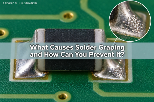
Technical illustration of solder graping on a small chip-component fillet, not an inspection photograph

What Does Solder Graping Look Like?

A graping solder defect usually appears as multiple rounded particles on the surface or edge of an otherwise coalesced solder deposit. Under magnification, the individual particle outlines remain visible instead of merging into the surrounding metal. Solder joint graping can be localized to the smallest pads while larger joints on the same assembly look normal.

A dull surface alone is not enough to identify graping. Lead-free joints can have a matte finish without containing uncoalesced powder. Record the component reference, affected termination and particle location; use consistent lighting and magnification when comparing boards. A photograph of a rough joint does not establish its root cause or electrical reliability.

Why Are Small Solder Paste Deposits More Vulnerable?

Small deposits expose a relatively large surface compared with the amount of paste available. During heating, flux can spread away from the upper particles. Those exposed particles then have less local protection against oxidation. This is why solder paste graping often concentrates around miniature components and small apertures rather than appearing uniformly across a board.

Two different geometries matter: the size of the whole printed deposit and the size of the powder particles inside it. A small deposit does not necessarily contain a finer powder grade, and changing powder grade does not correct an inconsistent print. Keep these variables separate when investigating the problem.
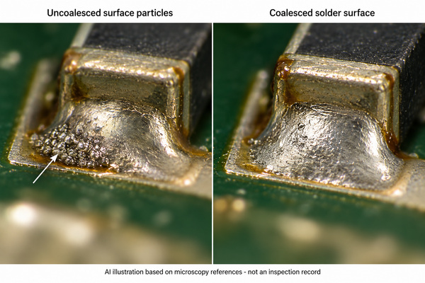
AI microscopy-style illustration comparing uncoalesced solder particles with a coalesced fillet; not an actual inspection record

How Do Oxidation and Flux Depletion Cause Graping?

Solder paste oxidation obstructs the joining of adjacent particles. Flux removes existing oxides and helps protect surfaces during heating, but its useful activity and coverage are finite. Prolonged thermal exposure, unsuitable paste chemistry or flux spreading can leave exposed powder insufficiently protected before coalescence occurs.

Melting and coalescence are not identical. A particle can reach the alloy's melting range yet remain separated by an oxide skin. Consequently, a peak temperature reading above liquidus does not prove that every surface particle joined the deposit. Conversely, visible graping does not prove that the whole joint stayed below liquidus.

Paste history belongs in the investigation: check the manufacturer's storage, thawing, handling and stencil-life requirements against the actual batch record. Do not add solvent or liquid flux to solder paste as an improvised correction. That changes the formulation and print behavior without establishing a qualified process.

Does Finer Solder Powder Increase Graping Risk?

For an equal volume of spherical metal, smaller particles have more total surface area. In the idealized geometry, surface area divided by metal volume is 6/d, where d is particle diameter. Halving d doubles that ratio. This explains the increased oxidation burden associated with finer powder; it is not a prediction that the defect rate will double.

Finer powder may still be necessary for small stencil apertures. Select the paste by its printing requirements and demonstrated reflow performance, not by choosing the coarsest or finest grade automatically. If a coarser grade is evaluated, verify release, deposit consistency and the smallest features before treating it as an improvement. A more oxidation-resistant formulation must also satisfy residue, cleaning and electrical requirements for the assembly.

How Do Stencil Apertures and Paste Volume Affect Graping?

The stencil opening specifies a theoretical volume, but the board receives only the paste that releases from it. Incomplete or variable transfer can leave vulnerable small deposits. For a rectangular opening with length a, width b and foil thickness t, the area ratio is ab/[2(a+b)t]. It compares opening area with aperture wall area; it is not a solder-graping acceptance ratio.

Consider an illustrative 0.20 × 0.25 mm aperture in a 0.10 mm foil. Its area ratio is 0.556 and its theoretical volume is 0.005 mm³. If the measured deposit is 0.004 mm³, transfer efficiency is 80%. Those numbers describe this example only: neither 0.556 nor 80% is a universal pass/fail threshold. Repeatability and the released process limits still matter.
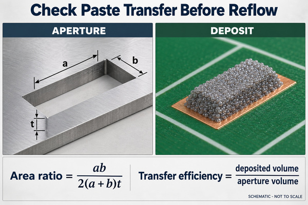
Rectangular stencil aperture and printed solder paste deposit with area ratio and transfer efficiency equations

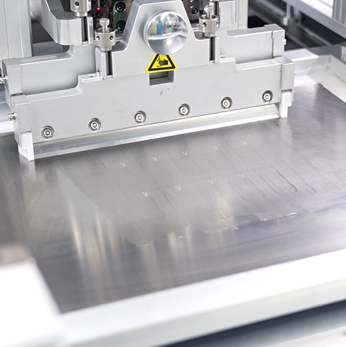
Our SMT stencils support the printing step where aperture geometry and paste release are established. On mixed-size assemblies, step-up and step-down stencils allow local foil-thickness changes, subject to spacing and printability review. Neither a thicker foil nor a larger aperture is an automatic cure: excess paste can create bridging or beading while a smaller area ratio can make release harder.

How Should You Adjust the Reflow Profile to Reduce Graping?

First measure the board, not just the oven settings. Place thermocouples at the affected small joint and representative high-thermal-mass and hot locations. Compare ramp, preheat or soak exposure, time above liquidus and peak against the selected paste's process window and the assembly's temperature limits.

If small deposits spend unnecessary time at elevated temperature before reflow, a shorter preheat or soak may preserve flux activity. However, shortening the profile must not leave heavy joints underheated. If the measured cold location fails the required process window, correct that deficiency rather than assuming every granular-looking joint has the same oxidation history.
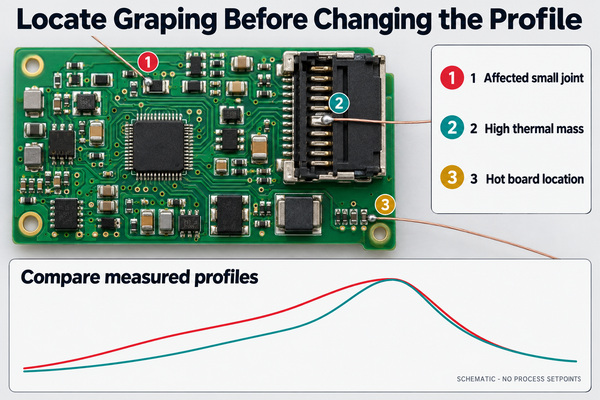
Illustrative thermocouple locations and qualitative profile comparison with no process setpoints

Avoid changing peak, conveyor speed, paste and stencil at the same time. A better-looking board would then provide little evidence about which change helped. Check wetting, bridging, tombstoning and temperature-sensitive parts alongside the graping result; a profile that reduces one defect but creates another is not ready for production.

Can Nitrogen Reflow Prevent Solder Graping?

Nitrogen can reduce oxidation during reflow and widen the usable process window. It does not replenish depleted flux, repair poor paste transfer or prove that every joint has received sufficient heat. Evaluate atmosphere with the same paste, deposit geometry and measured thermal conditions wherever practical.

Better wetting can also change solder distribution and the balance of forces at small chip components. Compare other defects as well as graping. Use the residual-oxygen conditions specified and qualified for the process; there is no single nitrogen setting that can be inferred from the word “graping.”

How Is Graping Different from Solder Balls, Cold Joints and Slump?

Location and formation history help separate these problems. The distinctions below guide investigation, not automatic acceptance of a delivered assembly.

Condition What distinguishes it What to check first
Graping Recognizable powder particles remain at the solder deposit surface after reflow Particle location, paste transfer, flux protection and the joint's actual profile
Solder balling or beading Separate balls or beads occur outside the intended joint, sometimes beside or beneath a chip Printing, paste displacement, placement and whether particles can move or bridge conductors
Cold solder joint An inadequately formed joint, potentially involving insufficient heat or poor wetting; surface dullness alone is inconclusive Joint formation, wetting and measured thermal history
Solder paste powder size A material specification before printing, not itself a defect Paste grade, aperture requirements and formulation compatibility
Slump Paste spreads or loses its printed shape before full reflow Cold/hot slump behavior, print-to-reflow delay and spacing

These conditions can coexist. Hot spreading can expose powder and contribute to graping, while displaced paste can form a separate bead. Classifying everything as “solder balls” obscures those different corrective actions. A board that passes a basic continuity check still requires assessment of loose conductive particles and the applicable workmanship requirements.

How Can You Confirm the Cause of Solder Graping?

Use a controlled comparison rather than judging one improved photograph. Define the affected component population and the inspection method before starting. The following order preserves evidence from the print stage through reflow:

  1. Keep a baseline. Record paste product, alloy, lot, handling time, stencil revision, printer setup and oven program. Photograph representative affected and unaffected joints.
  2. Check deposition. Compare SPI volume, area and height at the problem pads with their released limits. Examine variation across board positions and consecutive prints, not only the average.
  3. Measure the thermal history. Confirm the small-joint and heavy-joint profiles on the populated assembly. Record atmosphere conditions where nitrogen is used.
  4. Change one practical factor. Test a justified profile change, transfer improvement or qualified paste alternative against the baseline. Keep the other conditions recorded and controlled.
  5. Inspect the trade-offs. Count affected joints using the same denominator and examine wetting, bridging, beading and tombstoning. Retain the unsuccessful trial results as well as the improved sample.
  6. Repeat before release. Confirm that the improvement survives the planned production conditions and inspection requirements. One passing board is not evidence of a stable process.

For example, “12 affected terminations out of 400 inspected” is more useful than “graping is lower.” The example is a reporting format, not our production result. Include which termination types were counted so a change in the product mix does not masquerade as an improvement.

What Can We Check for Your SMT Assembly?

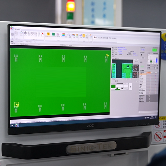
At EBest Circuit (Best Technology), our PCB assembly service includes solder-paste printing, 3D SPI, placement, reflow and inspection. Our equipment includes a SINIC-TEK S8080 3D SPI system, a Suneast SER710NH nitrogen-capable reflow oven and a SINIC-TEK A510DL 3D AOI system. SPI examines the deposit before reflow; AOI examines visible assembly features afterward. Neither independently establishes the chemical cause of uncoalesced particles.

For a graping concern on a planned build, send us the PCB files, BOM, affected component references and available inspection images. Existing paste, stencil and profiling information helps us assess the relevant printing and assembly conditions. We can discuss the build and inspection scope before quoting; process changes and acceptance criteria should be agreed for the specific assembly rather than inferred from a generic defect name.

Solder Graping FAQs

Can you remove graping by cleaning the board?

Cleaning residue does not make separated solder particles coalesce. Loose particles and suspect joints need a defined disposition and, where required, an approved rework process. Do not brush a cluster into surrounding circuitry or assume that a cleaner-looking surface demonstrates a sound joint.

Is there an IPC limit called a solder graping ratio?

Do not confuse stencil area ratio with an acceptance limit for graping. Use the applicable workmanship document, revision, class and customer requirements to assess the actual condition, including particle attachment, joint formation and electrical clearance.

Can a second oven pass fix graping?

A second pass with already depleted flux can add thermal exposure without correcting coalescence. Evaluate the cause and an approved rework method first, including component and board thermal limits. Repeated reflow is not a substitute for correcting the original print or thermal process.

Reducing solder graping means preserving flux effectiveness while achieving adequate joint heating and repeatable paste deposition. For SMT build review, contact us at sales@bestpcbs.com with the assembly files and affected joint details.
You may also like

Soldering Flux vs Soldering Paste: Which Should You Use?
Monday, May 25th, 2026

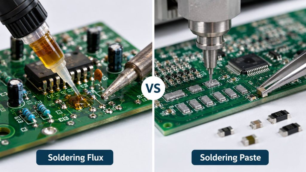
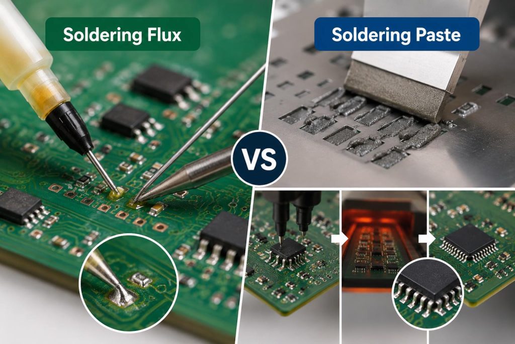
Soldering flux vs soldering paste comes down to one practical difference: flux prepares metal surfaces for soldering, while solder paste supplies both flux and solder metal. Use flux with solder wire, a solder bath, preforms, or existing solder. Use solder paste when the process requires a measured deposit of solder powder before heating, especially for surface-mount assembly.

The right choice depends on the assembly method, component footprint, alloy, and residue requirements. At EBest Circuit, we review these requirements alongside the BOM, stencil design, and inspection plan so material selection supports a repeatable production process.

Soldering Flux vs Soldering Paste

What Is the Difference Between Soldering Flux and Solder Paste?

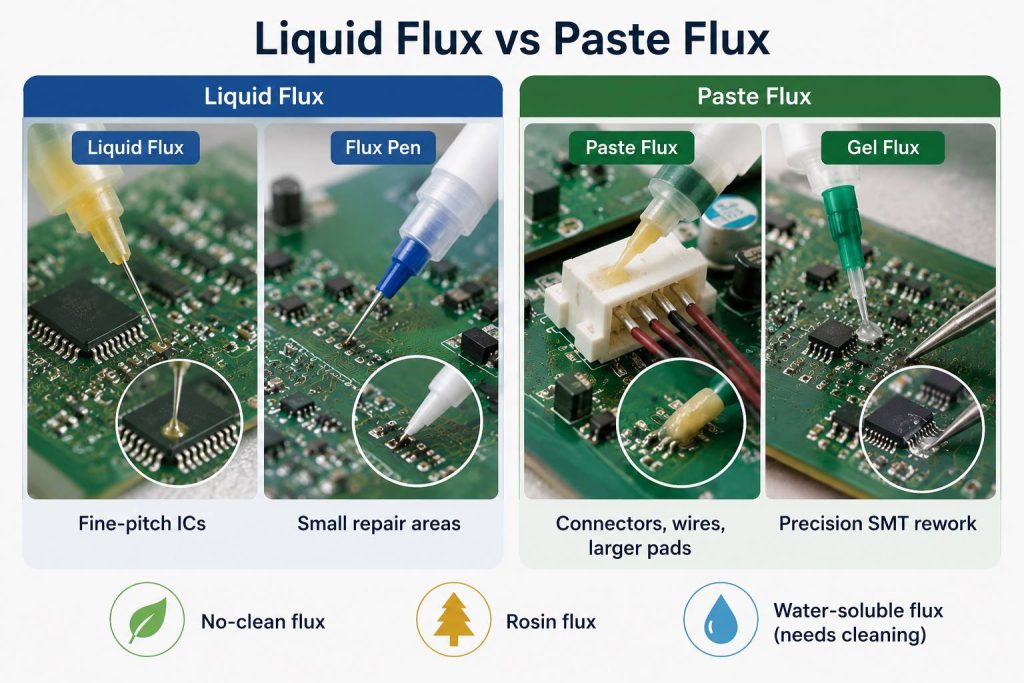
Soldering flux is a chemical preparation that removes surface oxides and supports solder wetting during heating. Solder paste combines a flux vehicle with fine metal powder; that powder melts and becomes the metallic connection.

This distinction matters when buying materials. A syringe labeled “paste flux” may contain no solder powder. A similarly packaged solder paste should identify its alloy, powder type, and metal loading.

Check the technical data sheet rather than relying on the product name or appearance.

Comparison pointSoldering fluxSolder paste
Main ingredientsActivators, carrier or solvent, and formulation-dependent resin or other ingredientsSolder alloy powder dispersed in a flux vehicle
Supplies solder metal?NoYes
Main functionSupports oxide removal and wettingDeposits solder metal and supports wetting during reflow
Common physical formsLiquid, pen, gel, or paste-like materialMetal-filled paste supplied in jars, cartridges, or syringes
Typical applicationPen, brush, spray, selective application, or dispensingStencil printing, jetting, or dispensing with a compatible formulation
Common processesHand soldering, wave soldering, selective soldering, and reworkSMT reflow and selected rework processes
Important specificationsFlux classification, solids content, activity, application amount, and residue behaviorAlloy, powder size, metal loading, rheology, working life, and reflow requirements
Source of the finished joint metalSeparate solder wire, bath, preform, or existing solderPowder contained in the paste
Cleaning decisionBased on flux chemistry, processing, and assembly requirementsBased on the paste’s flux system, processing, and assembly requirements

A solder paste deposit performs several jobs before it becomes a joint. It carries solder to the pad, maintains a printable or dispensable shape, and provides tack to help hold the component before reflow.

Flux applied separately has a different purpose. It assists a soldering operation in which the metal is supplied elsewhere.

What Does Flux Actually Do During Soldering?

Flux helps molten solder contact and spread across suitable metal surfaces. Its activators address oxides, while the formulation helps protect the heated interface during joint formation.

Good wetting produces contact between the solder and the pad or termination. Poor wetting may appear as solder pulling back, forming isolated beads, or leaving areas uncovered.

Ordinary flux does not change the melting point of the solder alloy. Its contribution is chemical surface preparation and support for wetting. If a joint receives insufficient heat, adding more flux alone will not solve the thermal problem.

Flux performance depends on several connected factors:

  • Surface condition: Pad finishes and component terminations need to remain within acceptable solderability conditions.
  • Activation window: The flux must remain effective during the relevant heating cycle.
  • Application amount: The deposit must cover the work area without creating unnecessary residue.
  • Thermal exposure: Heating must support solvent removal and activation while respecting assembly limits.
  • Residue requirements: The processed material must suit the electrical and protective-coating requirements.

For example, a clean connector pin may need only the flux already present in cored solder wire. A reworked fine-pitch device may benefit from a controlled application of compatible external flux.

Treat heavy oxidation as a material-condition issue as well as a soldering issue. Check storage history, surface finish, and component condition before choosing a more active formulation.

Soldering Flux vs Soldering Paste

What Is Inside Solder Paste, and Which Parameters Matter?

Solder paste contains alloy powder and a flux vehicle. The vehicle supports printing, tack, activation, and reflow behavior; the alloy determines the joint’s metallic composition.

  • SAC305: Sn96.5%, Ag3.0%, Cu0.5% by weight.
  • SAC0307-type: Sn99.0%, Ag0.3%, Cu0.7% by weight.
  • Sn63Pb37: Sn63%, Pb37% by weight; a lead-containing alloy that needs application-specific compliance review.

Alloy, powder type, and metal loading describe different properties. SAC305 identifies an alloy composition. Type 4 identifies a powder-size category. A value such as 88.5% identifies the metal loading by weight for a particular formulation.

The following grades show how powder size, metal loading and cleaning route vary independently. Match the complete grade to the intended printing and cleaning process.

Paste gradeAlloy composition by weightPowder typeMetal loading by weightFlux-system description
EM907 / T3 gradeSn96.5Ag3.0Cu0.5, commonly called SAC305Type 388.5%No-clean; contains halogen
EM907 / T4 gradeSn96.5Ag3.0Cu0.5Type 488.5%No-clean; contains halogen
WP616 / T4 gradeSn96.5Ag3.0Cu0.5Type 488.8%Water-soluble; zero-halogen
WP616 / T5 gradeSn96.5Ag3.0Cu0.5Type 588.3%Water-soluble; zero-halogen

These settings apply only to the named grades. A matching alloy or metal percentage does not make two paste formulations interchangeable.

An 88.5% metal loading also means that a 100 g quantity contains approximately 88.5 g of alloy powder and 11.5 g of flux vehicle. That is a mass relationship. It does not mean the paste deposit retains 88.5% of its printed volume after reflow, because the metal and vehicle have different densities.

Other useful parameters include viscosity, slump, tack time, stencil life, and response to printing pauses. Compare viscosity values only when the instrument, temperature, and measurement conditions are compatible.

Soldering Flux vs Soldering Paste

How Does Powder Size Affect Fine-Pitch Printing?

Powder size influences how readily solder paste passes through small stencil apertures. The relevant feature is the smallest aperture opening, together with stencil thickness and release behavior.

Common powder-size ranges are 25–45 µm for Type 3, 20–38 µm for Type 4, and 15–25 µm for Type 5. For initial aperture screening, allow five maximum-size particles across a rectangular opening and seven across a square opening or circular diameter.

Powder typeParticle diameter rangeLargest particle used in the screening calculationRectangular aperture width using five particlesSquare or circular aperture width using seven particles
Type 325–45 µm45 µm225 µm315 µm
Type 420–38 µm38 µm190 µm266 µm
Type 515–25 µm25 µm125 µm175 µm

Use these calculated widths as an initial screen, not a guaranteed printing limit. Check stencil area ratio as well; 0.66 is a common starting guideline. Aperture geometry, stencil finish, paste formulation and printing conditions determine actual transfer performance.

Consider a rectangular aperture that is 200 µm wide. Under the five-particle screening approach:

  • Type 3 requires 225 µm, so the opening falls below that guideline.
  • Type 4 requires 190 µm, so it passes that initial width screen.
  • Type 5 requires 125 µm, providing more particle clearance.

The next check is stencil release. For an illustrative 200 × 400 µm rectangular opening in a 100 µm stencil, the area ratio is:

Area ratio = opening area ÷ aperture wall area

Area ratio = (200 × 400) ÷ [2 × (200 + 400) × 100] ≈ 0.67

That calculation describes the geometry only. It does not prove acceptable transfer efficiency or solder-joint quality.

Finer powder also creates more exposed powder surface area. Choose a powder grade that prints consistently through the required features while maintaining a workable handling and reflow process.

When Should You Use Flux Instead of Solder Paste?

Use separately applied flux when the process already has a source of solder metal. Typical examples include solder wire for manual work, molten solder for wave or selective soldering, and existing solder during controlled rework.

Hand soldering and connector installation

Flux-cored wire supplies solder and internal flux together. External flux can help with selected joints, especially where additional surface activation is useful. Apply it locally and confirm compatibility with the wire’s flux and the cleaning process.

Wave and selective soldering

The solder bath supplies metal, so the separately applied flux prepares the board and component leads. Important controls include deposited solids, preheat, contact conditions, and residue behavior.

For a 951 low-solids no-clean wave-soldering flux, the process values are approximately 2.0% solids, 120–240 µg of deposited flux solids per cm², and 93–115°C component-side board preheat. The deposition value refers to dry flux solids, not the total wet liquid. The preheat value is a board temperature, not the solder-pot temperature. Apply these values only to this formulation and a qualified wave-soldering process.

Touch-up and desoldering

External flux can support wetting during bridge removal, solder-wick use, or joint touch-up. Select the form around access: a pen offers localized delivery, while a compatible tacky formulation stays near a rework area.

Liquid, gel, and paste-like flux describe delivery behavior. They do not establish activity level, residue acceptability, or cleaning requirements by themselves.

Soldering Flux vs Soldering Paste

When Is Solder Paste the Better Choice?

Solder paste is the better choice when the assembly requires solder deposited onto pads before components pass through a reflow process.

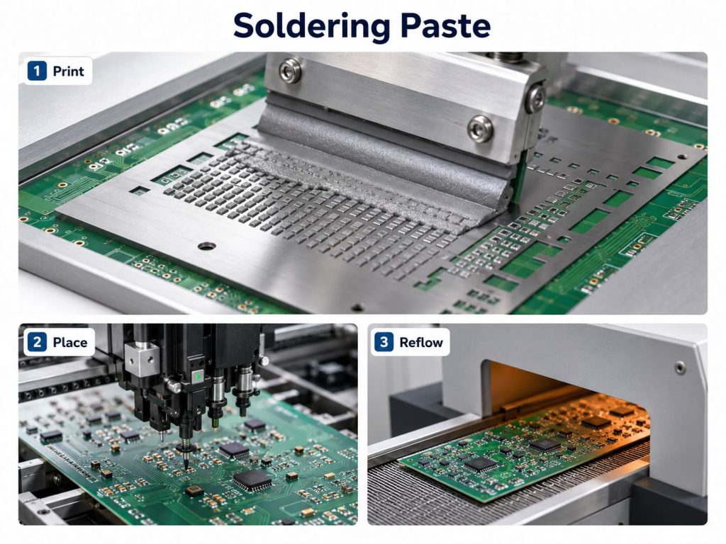
Stencil printing can apply many deposits in one operation. Placement equipment then positions the components, and the thermal cycle activates the flux, melts the alloy, and allows joints to form during cooling.

The material must suit the application method:

  • Stencil-printing paste needs suitable aperture filling, release, and shape retention.
  • Dispensing paste needs controlled flow through the specified delivery system.
  • Jetting paste needs a formulation qualified for the particular jetting equipment.

A syringe package alone does not establish that a material will dispense through every needle.

Solder volume deserves as much attention as paste chemistry. Excess deposit volume can contribute to bridging, while insufficient volume can contribute to weak or open connections. Stencil thickness, aperture dimensions, printing alignment, and transfer efficiency all affect the result.

Large thermal pads need particular care. Their aperture pattern should support suitable solder coverage and gas escape during reflow. Evaluate the component manufacturer’s footprint guidance alongside the printing and thermal process.

For prototypes, paste is useful when the build needs to represent the intended SMT process. Hand soldering may suit a simple test circuit, while printed paste and reflow provide more relevant information for a design moving toward automated assembly.

What should SPI check before component placement?

Solder paste inspection checks deposit volume, area, height and position. It helps detect missing paste, insufficient or excessive deposits and misalignment before reflow. Set acceptance limits from the approved stencil and assembly process; equipment resolution is not the same as measurement accuracy or a guaranteed detectable defect size.

Our SPI inspection accuracy can reach approximately 10 µm. Measurement accuracy is not a universal minimum detectable defect size; inspection limits still depend on the deposit geometry, inspection setup and assembly requirements.

Soldering Flux vs Soldering Paste

How Should You Compare Processing and Storage Parameters?

Compare specifications at the exact product-and-grade level. Keep storage life, stencil life, tack time, and printing-pause performance separate because each describes a different condition.

How do we handle solder paste before printing?

At EBest Circuit, our typical solder paste handling controls are:

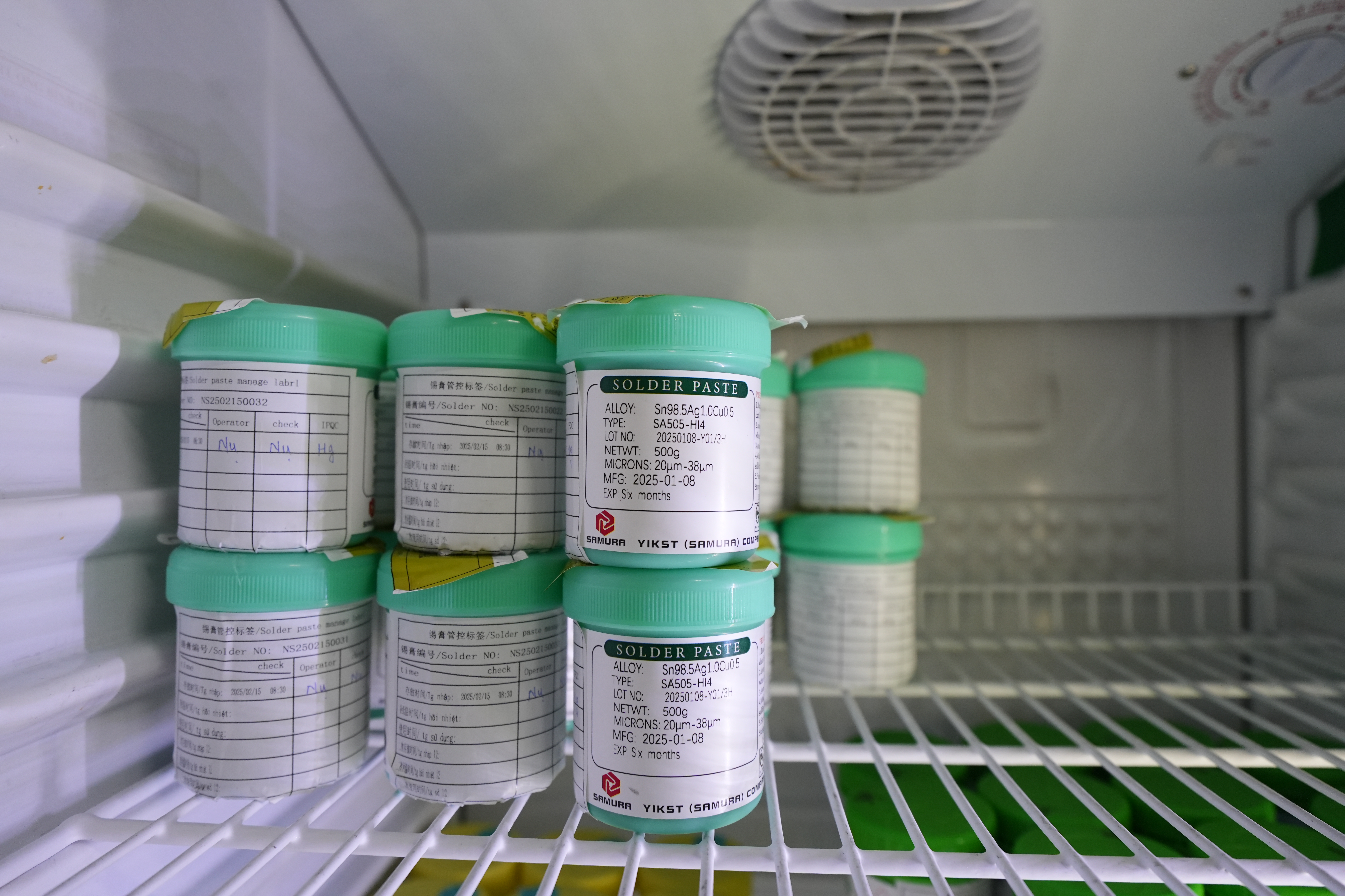
  • Refrigerated storage: 2–10°C. Keep containers sealed and track the material lot and expiration date.
  • Warm-up before use: about 4 hours. Keep the container sealed while the paste returns to its specified working temperature.
  • Mixing before printing: about 3 minutes. Use the approved mixing method for the selected paste.

These are our typical production settings. Apply any material-specific handling requirements for the approved paste and packaging.

Typical shelf-life ranges are 3–6 months for solder paste and 6–24 months for flux. The exact expiration date and storage conditions depend on the formulation and packaging. Use the product label and material specification to release each lot; shelf life is separate from open-container working life and time on the stencil.

How do formulation-specific specifications differ?

For the EP256 Sn63Pb37, 90% metal formulation, the following parameters illustrate the separate controls needed for storage and printing. They are not universal settings for lead-free or other solder pastes.

ParameterValue and conditions
Reference formulation for physical dataSn63Pb37, 90% metal
Typical viscosity1,400 poise (140 Pa·s) at 25°C; Malcom viscometer, 10 rpm
Optimal printing environment21–25°C and 35–65% RH
Stencil life8+ hours, process dependent
Printing-pause capabilityUp to 90 minutes under stated conditions
Recommended refrigerated storage0–10°C
Shelf lifeSix months from manufacture when properly handled at 0–10°C
Flux classificationROL1 under the referenced J-STD-004B classification

Keep the formulation, storage temperature and time limits together in the work instruction. Do not apply this six-month shelf life or 90-minute print pause to a different paste.

Keep refrigerated paste sealed while it reaches the specified working temperature, then open and mix it using the approved method. Container size, formulation and starting temperature affect warm-up time. Excessive or uncontrolled mixing can change paste temperature and rheology.

Record the material lot, expiration date, removal from storage, opening time, and permitted working exposure. This gives the production team a way to investigate printing changes without guessing about material history.

Does No-Clean Flux Mean the Board Never Needs Cleaning?

“No-clean” describes a formulation intended to leave residues suitable for specified applications when processed correctly. The final decision depends on the assembly’s electrical requirements, environment, and subsequent operations.

A board with sensitive analog inputs, close conductor spacing, protective coating, or demanding humidity exposure may require additional evaluation.

Review residue where it actually remains. Material trapped beneath low-standoff components can be harder to inspect and remove than exposed surface residue. Rework also introduces a separate application of flux, which may receive a different heating cycle from the original solder paste.

For water-soluble materials, establish the cleaning method, access, timing, rinsing, and drying requirements before production. “Water-soluble” identifies a cleaning characteristic; it does not define a complete cleaning procedure.

If cleaning is required, verify:

  1. Compatibility with components, markings, adhesives, and coatings.
  2. Access beneath the relevant packages.
  3. Removal of the particular flux residue.
  4. Suitable rinsing and complete drying.
  5. The inspection or testing needed for the application.

A visually clean board can still need further cleanliness assessment. Use the project’s requirements and appropriate validation method to decide acceptance rather than appearance alone.

How Do You Choose the Right Material for Your PCB Assembly?

Start with the operation that forms the joint, then narrow the material choice around the assembly.

First, identify the solder source. A reflow operation generally needs paste or another planned solder deposit. Manual soldering normally uses wire, while wave soldering uses a solder bath with separately applied flux.

Second, confirm the alloy requirements. Check compliance, component compatibility, thermal limits, and any approved material restrictions. A higher processing temperature does not automatically produce a stronger or more suitable joint.

Third, check the smallest printed feature. Review the stencil opening, thickness, area ratio, and paste grade together. Component pitch is useful context, but aperture dimensions provide a more direct printing check.

Fourth, agree on residue treatment. Select the no-clean or cleaning route before the first production build, including any coating or bonding operations that follow soldering.

Finally, validate the assembled result. Printing, placement, reflow, inspection, and electrical testing should confirm that the selected material works within the intended process.

A useful approval record includes the exact material code, alloy, powder grade, supplier documentation, storage controls, printing setup, measured thermal profile, and inspection results. Real records make repeat orders easier to control.

Soldering Flux vs Soldering Paste

How Can You Tell Whether a Defect Comes from Flux or Solder Paste?

Investigate the point where the process first departs from its expected result. A visible soldering defect may have several causes, so changing the flux or paste should follow evidence.

For bridging, inspect the printed deposit first. Check alignment, volume, aperture condition, and slump. Then review component placement and behavior during reflow. Additional flux is not a substitute for correcting excessive solder volume.

For incomplete wetting, check surfaces and heating together. Review pad finish, component solderability, contamination, material age, and the measured thermal profile. The flux must remain active when the surfaces need it.

For inconsistent printing, review handling and equipment. Check paste temperature, exposure history, stencil cleanliness, support, squeegee settings, and replenishment practices.

For residue concerns, compare material and process records. Confirm which paste and rework flux were used, how they were heated, and whether the cleaning procedure addressed both materials.

A controlled investigation changes one relevant factor at a time and compares measurable results. Useful evidence includes paste deposit measurements, microscope images, temperature profiles, defect locations, and material-lot records.

FAQs About Soldering Flux vs Soldering Paste

Q1: Can plumbing flux be used on a PCB?
A1: Use electronics-grade flux specified for the assembly because plumbing formulations can leave residues unsuitable for electronic circuits.

Q2: Is flux-cored solder wire enough for hand soldering?
A2: Flux-cored wire can supply sufficient flux for suitable clean joints, while additional compatible flux may help with selected surfaces or rework operations.

Q3: Can dried solder paste be restored by adding liquid flux?
A3: Additives change the formulation, so use only a recovery method explicitly approved by the paste manufacturer.

Q4: Can two solder paste brands be mixed on the stencil?
A4: Keep materials separate unless the combination has been specifically approved and validated for the process.

Q5: Is lead-free solder paste automatically halogen-free?
A5: Lead content describes the alloy, while halogen content describes a separate material characteristic that requires its own declaration.

Q6: Is tacky flux suitable for BGA reballing?
A6: A tacky flux may suit BGA reballing when its manufacturer specifies compatibility with the alloy, thermal cycle, and residue requirements.

Q7: Does a dull solder joint mean the flux failed?
A7: Joint appearance depends on alloy, finish, geometry, and processing, so dullness alone does not establish a flux failure.

How Can EBest Circuit Support Your Soldering Material Selection?

For a PCB assembly project, material selection works best when it is reviewed with the board layout, component packages, manufacturing sequence, and required inspection.

We review production files and discuss the soldering requirements alongside PCB fabrication, component sourcing, assembly, and project-defined testing. The review should identify material restrictions, fine-pitch features, heat-sensitive components, cleaning expectations, and any customer-approved process requirements.

Send your Gerber files, BOM, pick-and-place file, quantities, and testing requirements to sales@bestpcbs.com. Include any specified solder alloy, approved paste or flux, cleanliness requirements, and coating needs so these conditions can be considered before quotation and production planning.

You may also like

How to Use Soldering Paste? Types of Flux in Soldering
Friday, December 26th, 2025

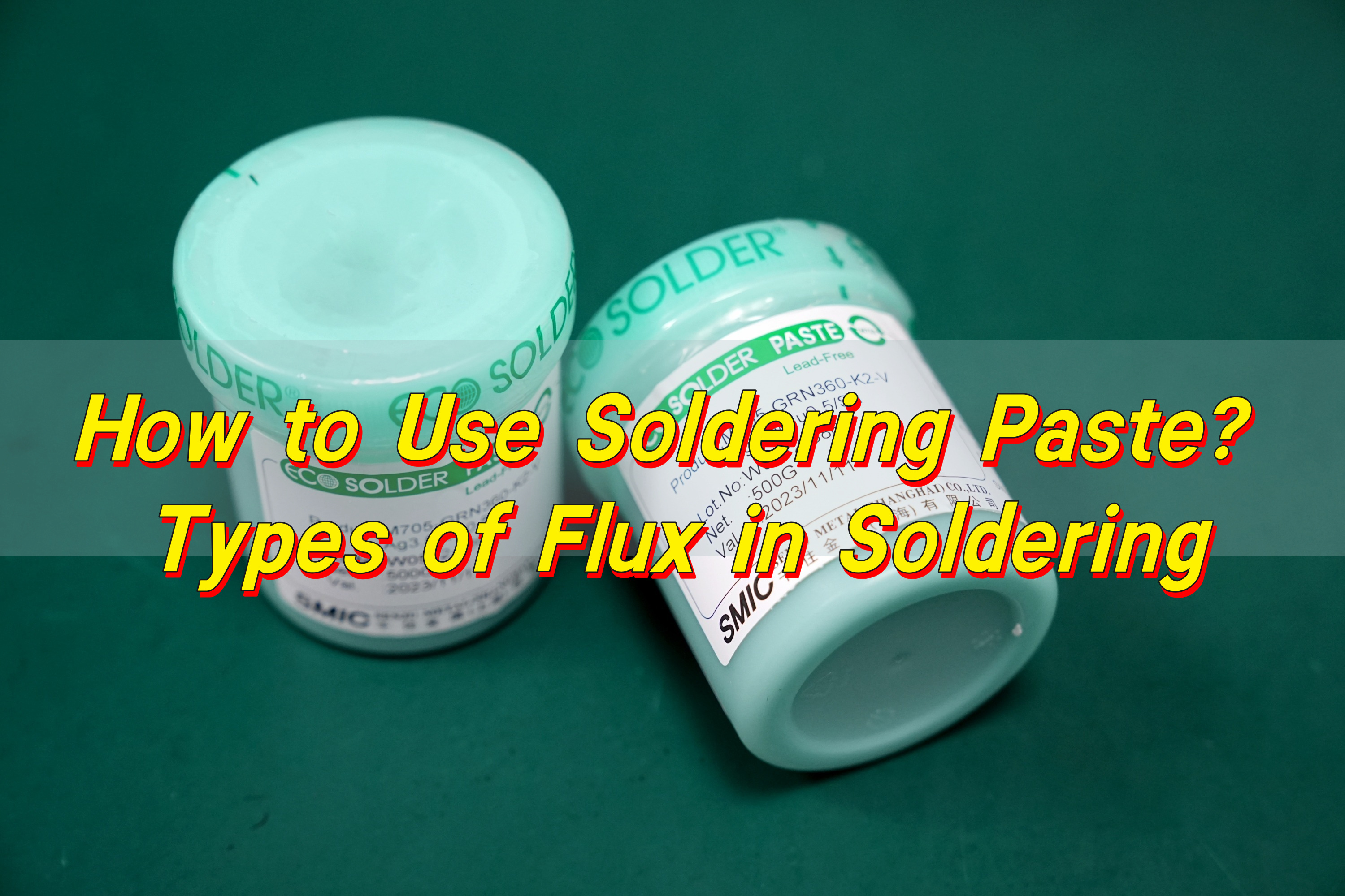
How to Use Soldering Paste? Soldering paste is a blend of tiny metal alloy particles and flux. It helps components bond to PCB pads during reflow. To use it, apply a small, even amount of paste to clean pads, place the component on top, and heat the area with a reflow oven or hot-air tool.

How to Use Soldering Paste? Types of Flux in Soldering

What Is Soldering Paste?

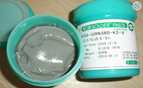
Soldering paste, also called solder paste, is a mixture that includes tiny metal alloy particles combined with a flux medium. It is soft, grey, and sticky. Engineers apply it to copper pads before placing components. After heating, the alloy melts, forms a bond, and creates electrical continuity.

In SMT production, solder paste acts like glue before reflow and becomes a strong metallic joint afterward. The paste stays in place during part placement. It wets surfaces when heated. It also removes mild oxidation.

You will see different types of solder pastes across the industry. Most of them follow either Sn-Pb or lead-free formulas. The choice depends on your process, compliance needs, and product application. Lead-free pastes dominate now since RoHS and other environmental rules require safer materials.

Types of Flux in Soldering

Flux is the active agent inside solder paste. Its job is simple but critical. It removes light oxidation, keeps surfaces clean, and helps molten solder spread.

There are several flux varieties. Each type serves a different function, depending on the complexity of your assembly, the metal surfaces involved, and the heating method.

1. Rosin Flux

Rosin flux comes from natural pine resin. It is stable, safe, and effective for a wide range of soldering tasks.

Rosin flux is available in different activity levels:

  • R (low activity)
  • RMA (medium activity)
  • RA (high activity)

RMA is the most common. It strikes a balance between cleaning strength and low residue.

2. Water-Soluble Flux

Water-soluble flux uses organic acids and delivers stronger cleaning power. It is great for high-density circuits, oxidized surfaces, and complex PCBs.

Because residues are more active, water cleaning after reflow is required. This is one reason why it is popular in medical and industrial equipment production, where cleanliness is essential.

3. No-Clean Flux

No-clean flux leaves very small residues. These residues are safe, non-conductive, and do not need washing in most cases.

This flux is ideal for high-volume production where cleaning would increase cost. No-clean formulas save time, lower expense, and improve throughput.

4. Halogen-Free Flux

Halogen-free flux removes halogen compounds that can release corrosive by-products. This flux is widely used in green electronics, LED circuits, and consumer devices. It is stable and safe for long-term applications.

What Is Soldering Flux Made Of?

Flux ingredients vary depending on the type, but most formulas include these key components:

  • 1. Activators

Activators break down surface oxides. They are mild acids or chemical compounds. Their strength determines how much cleaning power the flux offers.

  • 2. Resins or Carriers

Resins form the base of rosin and no-clean flux. They provide viscosity and help residues stay stable.

  • 3. Solvents

Solvents keep the paste flexible during printing and help it spread properly. They evaporate at high temperatures.

  • 4. Additives

Additives control wetting, adhesion, viscosity, and residue color. They fine-tune performance for different use cases.

How to Use Soldering Paste? Types of Flux in Soldering

When everything works together, the flux streamlines the soldering process. It keeps the joint clean during heating, promotes good wetting, and improves overall reliability.

What Do You Do With Soldering Paste?

Solder paste has one main purpose: to bond components to PCB pads. But it offers other functions too. You can use solder paste for:

  • SMT soldering
  • Small electronic repairs
  • Replacing QFN, BGA, or fine-pitch ICs
  • Reflow soldering
  • Hot-air soldering
  • Tin filling on small pads
  • Creating small metallic joins on test boards

It is not only a bonding material. It also ensures proper alignment and contact. Component placement machines rely on the adhesive quality of paste to hold parts steady before heating. This prevents movement and reduces defects.

Solder paste is essential in almost every production environment. It helps create strong, reliable joints used in phones, computers, robots, medical devices, and industrial systems.

How to Use Solder Paste Correctly?

Using solder paste correctly is essential if you want stable joints and good yields. The process is simple, but every step matters. Here is a clear, step-by-step guide.

Step 1. Prepare the Surface

Clean surfaces lead to strong solder joints. Wipe pads with isopropyl alcohol if needed. Remove grease, dust, oxidation, and fingerprints.

A clean pad helps the solder wet properly. Good wetting increases strength and lowers defect rates.

Step 2. Apply the Paste

There are two main ways to apply solder paste:

  • Method A: Stencil Printing

Most SMT factories use stainless steel stencils. The stencil spreads paste on each pad with controlled thickness. The print is clean, uniform, and repeatable.

  • Method B: Manual Application

For home repairs or prototypes, you can use a syringe. Push small dots of paste onto each pad. Keep the amount small and even. Too much paste can cause bridging.

Step 3. Place the Component

Place the component onto the pasted pads. The paste will hold it in place before heating. This tackiness prevents shifting. Manual tweezers or pick-and-place machines both work well.

Step 4. Heat the Joint

Reflow the paste using:

  • A reflow oven
  • A hot-air gun
  • A hot plate
  • An SMT rework station

The heat melts the alloy. Flux activates. Oxides break down. Wetting occurs. The solder shrinks into a glossy, stable joint.

Make sure you follow the correct temperature curve. Good reflow depends on controlled heating.

Step 5. Let It Cool

Cooling should be even and smooth. After cooling, inspect the joint. A good solder joint looks shiny and well-formed.

How to Use Soldering Paste? Types of Flux in Soldering

Do I Need Flux for Solder Paste?

You do not need extra flux when using solder paste. That is because solder paste already includes flux in its formula. The flux inside the paste is optimized for wetting, cleaning, and bonding.

Adding more flux may help in rare special cases, but it is usually unnecessary. Too much external flux may leave extra residue or cause splattering during heating.

What Happens If You Don’t Use Flux When Soldering?

Flux is essential when soldering bare wire or loose solder. Without flux, oxidation will remain on the metal surface. The solder will not wet properly. The joint becomes weak and unreliable.

Here are the common outcomes when flux is missing:

  • Poor wetting
  • Weak joint strength
  • Grainy or dull surface
  • Increased bridging probability
  • Higher defect ratio in production
  • Risk of intermittent electrical contact

These issues make flux a must-use material for any reliable soldering process.

Can Solder Paste Be Used on All Metals?

Solder paste works well with common PCB metals, such as:

  • Copper
  • Tin
  • Silver plating
  • Gold plating
  • ENIG finishes
  • HASL finishes
  • Immersion tin
  • Immersion silver

However, it does not bond effectively with some metals, such as:

  • Aluminum
  • Stainless steel (without special flux)
  • Nickel alloys (unless pre-treated)
  • Oxidized surfaces

If your metal surface resists wetting, you may need a specialized flux or pre-treatment.

How Long Does Soldering Paste Last?

Solder paste does not last forever. Over time, solvents evaporate, flux loses activity, and metal particles oxidize. All these factors weaken printing quality and reduce wetting.

Most solder pastes last:

  • Around 6 months refrigerated
  • Around 1 month at room temperature
  • Around 24 hours after opening, depending on humidity and airflow

To prolong lifespan, store it in a refrigerator around 2°C to 10°C. Warm it to room temperature before use. Do not open cold paste, or moisture will condense inside.

How to Use Soldering Paste? Types of Flux in Soldering

Common Problems When Using Solder Paste

Here are some issues that users may face, and what causes them.

  • 1. Bridging

Too much paste or misaligned stencils create solder bridges.

  • 2. Voids

Improper reflow or contaminated pads produce internal voids.

  • 3. Tombstoning

Uneven heating or different pad sizes cause components to lift.

  • 4. Incomplete Reflow

Low temperature prevents full melting.

  • 5. Slumping

Low-quality paste spreads too much before heating.

All these issues are easy to prevent with good control and proper technique.

Conclusion:

Solder paste is a powerful material that makes modern electronics possible. It supports clean joints, stable conductivity, and quick assembly.

If you need help with SMT production, solder paste selection, or high-precision PCB assembly, EBest Circuit (Best Technology) can support you with professional guidance and reliable manufacturing.

For inquiries, please contact: sales@bestpcbs.com

You may also like

What is solder paste? What is its function?
Thursday, August 29th, 2024

What is the role of solder paste? Electronic devices have been deeply integrated into our daily lives. Whether it is mobile phones, tablets or household appliances, they are inseparable from electronic components. How are these components accurately soldered to the circuit board? The answer lies in surface mount technology (SMT) and the important material it uses – solder paste.

In the process of SMT patch processing, solder paste is an indispensable and important material. The quality and use method of solder paste directly affect the welding effect and the performance of the final product.

What is the composition of solder paste?

Solder paste is a complex mixture of multiple components, and its main components include metal powder, flux and solvent.

What is solder paste? What is its function?

The metal powder in solder paste is usually composed of metal alloys such as tin, silver and copper. The particle size and distribution of metal powder have a direct impact on the welding effect. The smaller the particle size, the more uniform the distribution, and the better the welding effect.

At the same time, the composition of the metal alloy also determines the mechanical strength and electrical properties of the solder joint.

Flux is another important component in solder paste. Its main function is to remove oxides on the welding surface and improve the wettability and reliability of welding.

The type and formula of flux directly affect the melting state and solder joint quality during the welding process. Common fluxes include rosin-based flux, organic acid flux and halogen-free flux.

Solvents are used to adjust the viscosity and printing performance of solder paste. Appropriate viscosity can ensure that the solder paste is evenly distributed during the printing process without problems such as drawing and collapse. The evaporation rate of the solvent will also affect the drying time and welding performance of the solder paste.

What is the role of solder paste in SMT patches?

In the SMT (surface mount technology) patch processing process, solder paste plays a vital role. It is not only used to bond components, but also the key to ensure the quality of electrical connections and mechanical strength.

1. Bonding components

One of the main functions of solder paste is to bond components. After the solder paste is accurately printed on the pads of the PCB (printed circuit board), the pins or contact points of the electronic components will be placed on the solder paste. The solder paste melts during the reflow soldering process to form a strong bond, ensuring that the components are stably attached to the PCB.

2. Provide electrical connection

Solder paste melts during the reflow soldering process and forms metal solder joints, which not only bond components but also provide electrical connections. Good electrical connections ensure the effective transmission of electrical signals on the PCB, which is the basis for ensuring the normal operation of electronic equipment.

The solder joints formed by the metal components (such as tin, silver, and copper) in the solder paste after melting have excellent conductivity, ensuring the reliability and stability of electrical connections.

3. Ensure mechanical strength

The mechanical strength of the solder joints is the key to ensuring the stable operation of electronic components in various environments. The solder joints formed by the solder paste after reflow soldering have sufficient mechanical strength to resist external stresses such as vibration, impact, and thermal expansion and contraction. This not only protects the components and PCB, but also improves the reliability and service life of the entire electronic equipment.

Is solder paste the same as flux?

Solder paste and flux are not the same. ‌

Although both solder paste and flux are materials used in the welding process, their functions and uses are different.

Solder paste is a paste-like viscous body, the main components of which include metal powder, rosin, organic acid, thixotropic agent, and activator, and is used for welding in SMT automatic mounting process.

Flux is a liquid, a mixture with rosin as the main component, which is used to remove oxides on the surface of solder and the base material to be welded, so that the metal surface reaches the necessary cleanliness, prevents the surface from re-oxidation during welding, reduces the surface tension of the solder, and improves welding performance.

In general, although both solder paste and flux are indispensable materials in the welding process, they have obvious differences in form, function, and usage.‌

What is the storage method of solder paste?

The correct storage method can extend the service life of the solder paste and ensure its stable performance.

1. Temperature control

Solder paste should be stored in a low temperature environment, usually 0-10℃. Excessive temperature will cause the solvent in the solder paste to volatilize, affecting its viscosity and printing performance. Avoid direct sunlight and high temperature environment during storage to prevent the solder paste from deteriorating.

2. Humidity control

Humidity has a great impact on solder paste. Excessive humidity will cause the solder paste to absorb moisture, affecting its printing performance and welding quality. The relative humidity of the storage environment should be controlled below 50% to ensure the stability of the solder paste.

3. Sealed storage

The solder paste should be stored in a sealed container to prevent oxygen and moisture from entering the air. The solder paste after opening should be used up as soon as possible, and the unused solder paste should be resealed and stored in a low temperature environment.

How to use solder paste correctly?

1. Reheating treatment

The solder paste stored in a low temperature environment should be reheated before use. The reheating time is usually 4-8 hours. During the reheating process, it should be avoided to be directly exposed to a high temperature environment to prevent the solvent in the solder paste from volatilizing. The solder paste after reheating should be fully stirred to ensure that the metal powder and flux are evenly distributed.

2. Printing process

Solder paste printing is a key process in SMT patch processing. During the printing process, the scraper pressure, printing speed and template opening size should be controlled to ensure that the solder paste is evenly distributed on the pad. The printed solder paste should have a good shape and should not have problems such as drawing and collapse.

3. Solder paste reflow

The solder paste reflow process is the process of melting the solder paste and forming a firm solder joint with the pad and component pin. The temperature curve should be controlled during the reflow soldering process to ensure that the solder paste melts at an appropriate temperature and fully wets the pad and pin. Too high or too low reflow temperature will affect the welding quality.

4. Solder joint detection

The quality of the solder joint is an important indicator for evaluating the welding effect. After the welding is completed, the solder joint detection should be carried out to check the shape, size and wettability of the solder joint. Qualified solder joints should have a smooth and complete surface without defects such as solder balls and cold solder joints.

What is solder paste? What is its function?

Conclusion:

Solder paste plays a vital role in SMT patch processing. Its composition, selection, storage and use methods directly affect the welding quality and the performance of the final product. By understanding and mastering the relevant knowledge of solder paste, the quality of SMT patch processing can be effectively improved, and defects and rework rates can be reduced.

BEST Technology has rich experience and strict control standards in the selection and use of solder paste, and can provide customers with high-quality SMT patch processing services. If you have any questions about our products or services, please feel free to contact us. Choose BEST Technology , choose quality assurance.

You may also like

How to Clean Flux Off PCB? – EBest Circuit (Best Technology)
Wednesday, July 31st, 2024

Flux is usually a mixture of rosin as the main component and is an auxiliary material to ensure the smooth progress of the PCB soldering process. Soldering is the main process of PCB assembly, flux is the auxiliary material used in soldering. The main function of flux is to remove the oxide of the solder and the base metal surface to be welded, so that the metal surface to achieve the necessary cleanliness.

Flux prevents the reoxidation of the surface during welding, reduces the surface tension of the solder, and improves the welding performance. The performance of flux directly affects the quality of electronic products. There are different types of solder paste flux, including rosin-based, water-soluble, and no-clean flux. Each has its specific applications and cleaning methods.

Types of Flux

  • Rosin Flux

This is one of the most commonly used fluxes in soldering. It includes activated rosin flux (RMA), which contains additional chemicals for enhanced cleaning of oxides, and non-activated rosin flux (RA), which offers basic cleaning for general purposes. Rosin flux is effective at preventing oxidation and improving solder flow, making it suitable for a wide range of electronic soldering applications.

  • Water-Soluble Flux

This type of flux uses water-soluble chemicals to provide strong cleaning action. It is easily removed with water, making it ideal for applications where thorough residue removal is necessary. Water-soluble flux is often used in automated soldering processes where post-soldering cleanup is a key concern.

  • No-Clean Flux

Designed to leave minimal, non-corrosive residue, no-clean flux does not require cleaning after soldering. This type of flux is beneficial in situations where cleaning is difficult or impractical, as it reduces post-soldering processing time while ensuring that the residue does not affect the performance of the PCB.

  • Organic Acid Flux

Contains organic acids like citric or formic acid, providing effective cleaning and fluxing. While it offers strong fluxing action, it is more corrosive compared to rosin fluxes. Organic acid flux is used in applications requiring robust cleaning, with careful consideration of the corrosion risk.

  • Solder Paste Flux

This flux is a combination of flux and solder powder, used in reflow soldering processes. It is commonly employed in surface-mount technology (SMT), where the paste is applied to PCB pads before component placement and reflow. Solder paste flux streamlines the soldering process by integrating fluxing and soldering into one step.

Is it Bad to Leave Flux on PCB?

There is obvious that leaving flux residue on a PCB surface can lead to several issues. Flux residues can attract moisture, resulting in corrosion of metal traces and component leads, which can compromise the integrity of the PCB over time. Some flux residues are conductive, potentially causing short circuits and affecting signal integrity, especially in high-frequency applications. Even no-clean flux can leave residues that impact sensitive components. Cleaning flux off the PCB can make sure the optimal performance and reliability of the overall product.

How to Remove Flux After Soldering?

We know leaving the flux on the PCBA surface is not a good thing, so how to remove it? Here we listing some common methods that manufacturers will used after soldering. Hope this information is helpful for you!

  • Isopropyl Alcohol (IPA)

Use high-purity IPA (90% or higher). Apply it to the flux residue with a brush or cotton swab, gently scrubbing the area to dissolve the flux. IPA evaporates quickly and is effective for most flux types.

  • Water Washing

Water washing is a common and straightforward cleaning method. It uses pure or deionized water to remove flux residues. This technique is simple, cost-effective, and easy to implement. However, water washing can potentially harm some PCBs and components if moisture accumulates on pads and pins, leading to short circuits or corrosion.

  • Solvent Cleaning

Solvent cleaning is an efficient method that dissolves flux residues using chemical solvents. The solvent is then rinsed or sprayed off to clear the flux. While this method provides rapid and effective cleaning, solvents can be costly and require careful handling due to their chemical properties and safety considerations.

  • Ion Cleaning

Ion cleaning is a high-tech approach that uses ion beams to clean the surface of PCBs. The high-energy and high-speed ion beams effectively remove contaminants and flux residues without damaging the PCB or components. However, ion cleaning equipment is expensive and requires specialized technology and support.

  • Oxidation Cleaning

Oxidation cleaning is a physical cleaning method where oxidizing agents convert flux residues into easily removable substances. This technique is suitable for PCBs and components that are not compatible with water or solvent cleaning. The cost of oxidizing agents can be high, and safety precautions are necessary due to their reactive nature.

  • Dry Ice Cleaning

Dry ice cleaning uses CO2 dry ice pellets as the cleaning medium. This method is efficient, environmentally friendly, and does not produce secondary pollution. During cleaning, high-speed CO2 dry ice pellets impact the flux residues on the PCB surface. The extremely low temperature of the dry ice causes the flux residues to become brittle, allowing them to be easily removed without damaging the PCB. This method offers a thorough cleaning solution while preserving the integrity of the circuit board.

FAQs

1. Can I use vinegar to clean flux off a PCB?

Vinegar can be used to clean certain types of flux, but it’s not as effective as IPA or specialized flux removers. It’s best to use a solvent designed for flux removal.

2. How often should I clean my PCB?

Clean your PCB after every soldering session to prevent residue buildup and ensure optimal performance.

3. Is it safe to use a hairdryer to dry a PCB after cleaning?

Yes, but use the lowest heat setting to avoid damaging sensitive components. Ensure the PCB is completely dry before powering it on.

4. Can I use a toothbrush for cleaning flux?

A toothbrush can be used, but a brush with anti-static properties is recommended to prevent static damage to the PCB.

5. Is no-clean flux really safe to leave on a PCB?

While designed to be left on, no-clean flux can still leave residues that may affect sensitive components. It’s best to clean it off for maximum reliability.

All in all, cleaning flux off your PCB is a crucial step to keep the reliability of your product. Remember, a clean PCB is a reliable PCB. Choose the right solvent, follow proper cleaning techniques, and your electronics will thank you with years of flawless performance.

For high-quality PCB & PCBA solutions and expert advice, choose EBest Circuit (Best Technology). We have more than 18 years in this field. Our commitment to excellence ensures your projects are in good hands. Contact us today to learn more about our products and services.

You may also like

Dry Soldering: How to Prevent and Fix Dry Solder Joint?
Thursday, July 25th, 2024

It’s essential to ensure that solder joints are made correctly in any electronics construction. Poor and dry soldering cause equipment not to work once. Or there is a possibility that the solder joint could fail. In this blog, we will introduce why dry soldering occurs and how to solve it.

What is Meant by Dry Soldering?

Dry soldering refers to a poor solder joint that lacks proper electrical connectivity on a PCB assembly product. This issue occurs when the solder does not properly melt and bond to the components, leading to weak connections. These joints are often brittle and prone to failure, which can result in intermittent or complete loss of electrical connectivity.

Dry Soldering: How to Prevent and Fix Dry Solder Joint?

Why Dry Solder Joint Causes?

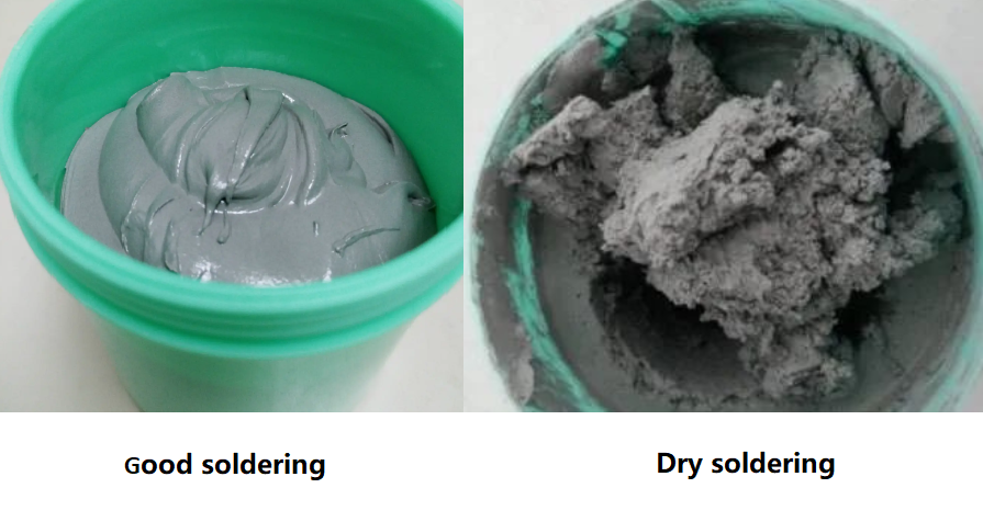
Dry solder joints occur due to several reasons, each impacting the quality of the solder connection. First of all, the solder paste reflow process is only a small area, which is easier to harden than the solder paste in the solder paste can. At this time, the solder paste will not melt, and the flux cannot cover the solder joint, resulting in poor welding of the solder joint. Meanwhile, the solder paste is easier to heat transfer, and the high temperature actually makes the solder paste not easy to melt, so we can slightly adjust the reflow welding temperature curve to solve the problem, or welding in a nitrogen environment is basically a good way to solve this problem.

Secondly, the solder paste does not melt because its own composition contains a very volatile flux, which is also the reason why the solder paste is easy to harden. Among them, the flux with the largest content of solder paste is rosin, rosin contains a lot of rosin acid, rosin acid is easy to lose activity at too high temperature. Therefore, the temperature of the welding process should be controlled to ensure that the temperature is about 200 ° C, which is not suitable for too high or too low. At the same time, the quality of thixotropic agent will also lead to the solder paste is easy to dry, the quality of thixotropic agent is not good will affect the viscosity of the solder paste, the viscosity of the solder paste is easy to dry. Therefore, the choice of high-quality solder paste can fundamentally solve the problem that the solder paste is easy to harden.

In addition, the use of solder paste scene, humidity, temperature and other external factors will also affect the solder paste in the use of hard non-melting phenomenon. So these external factors should be paid attention to. I hope these solutions can solve your problems.

How Do You Fix Dry Solder?

Solder paste is one of the very important materials in the electronics industry, and it has an important impact on the production quality of the entire component. Here are some tips that can help to fix the dry solder paste.

1.Add flux

              Usually, if the solder paste is too dry, you can try to add some water to the right amount of flux, stir well and add it to the solder paste. This can play a certain role in alleviating drying and improve the fluidity of the solder paste.

              Dry Soldering: How to Prevent and Fix Dry Solder Joint?

              2. Take some measurements during management

                a. Keep the ambient temperature moderate during storage;

                b. Stir well before use;

                c. Cover the solder paste in time after welding to avoid exposure to the air.

                3. Replace it with new one

                If the solder paste becomes too dry, adding flux is difficult to restore its original properties, it is recommended to replace the solder paste to avoid affecting the quality of the components.

                Therefore, we need to regularly maintain and manage the solder paste to ensure that its quality meets the standard requirements.

                What Does a Dry Solder Look Like?

                Recognizing a dry solder joint is crucial for proper diagnosis and repair. Unlike a good solder joint, which is shiny and smooth, a dry joint looks matte and rough. The joint might have visible cracks or look brittle. It might not be fully bonded to the component lead or the PCB pad. Identifying these visual cues can help in quickly addressing the issue.

                How Do You Prevent Dry Solder?

                Preventing dry solder joints is key to maintaining the reliability of your electronic projects. You can try to use these tips to prevent your solder paste become dry.

                • Proper heating
                • Clean surfaces
                • Use quality solder
                • Steady hand
                • Maintain equipment
                • Fast usage and storage

                If you want to know more about solutions of dry solder paste, you can read our another post, How to Solve Dry Solder Paste.

                How to Tell If Solder is Bad?

                Bad solder can lead to dry joints and other issues. So, how can we identify if my solder paste is bad? May you can follow these points. If everything matches up, there’s no doubt that your solder paste is broken.

                • Appearance of solder joints

                Bad solder joints often appear dull or matte instead of shiny and smooth. They may also show cracks or a brittle texture, indicating poor bonding or excessive heating. These visual signs suggest that the solder did not properly melt or flow.

                Dry Soldering: How to Prevent and Fix Dry Solder Joint?
                • Solder flow and coverage

                If the solder does not adequately cover the component leads or PCB pads, or if it spreads unevenly, it is likely bad. Proper soldering should result in a well-formed, consistent fillet around the leads, ensuring reliable electrical connections.

                • Difficulty in melting

                Solder that requires unusually high temperatures or takes a long time to melt may be old or contaminated. Proper solder should melt easily at the recommended temperature and flow smoothly to create a solid joint.

                • Contamination indicators

                Oxidized or tarnished solder indicates contamination and can affect its performance. Excessive residue or debris also points to poor quality, affecting how well the solder adheres and flows.

                EBest Circuit (Best Technology) is a one-stop PCB manufacture and PCBA service provider, our SMT factory is equipped with more than 6 assembly lines. Meanwhile, we have automatic SPI machine and solder paste printing machine, with good management system, we can ensure the good quality of solder paste. In addition, there are many advanced equipment in our workshop, including online dual AOI, X-ray, Nitrogen reflow oven, dry-ice cleaning machine, and so on.

                Trust us, we are the one of most reliable PCBA manufacturer in China and Vietnam. Contact us for more.

                You may also like

                Differences Between Solder Mask and Solder Paste in PCB
                Wednesday, December 7th, 2022

                When it comes to solder mask and solder paste, there are some engineers confused about their functionalities and even most of laymen thought they are the same, this is not hypothetical, it is real that happened to me. So today let’s explain differences between Solder Mask and Solder Paste for you.

                Part 1: What is Solder Mask?

                If you had ever seen a printed circuit board, you may see there is a layer of green ink cover on the PCB surface while some orange-yellow areas didn’t cover by ink. In PCB industry, the green ink we called Solder Mask, or abbreviated as S/M, and exposed area is copper, they were leave as GND plane or soldering pads to mount electronic components.

                Solder mask is a liquid acrylic oligomer, which has variety of colors such as red, blue, green, white, black. Green is commonly used in the process of PCB manufacturing, so some professional engineers call it as green oil.

                Solder_mask

                Solder mask applied on the PCB designed as a protection layer to avoid oxidation, corrosion and other environmental impacts when they leave production line. In addition, solder mask between solder pads also can help to prevent forming to solder bridge when assembly.

                Below are some other functions of coating a layer solder mask:

                • Prevent physical line breaking of copper trace
                • Only weld in the area that must be soldered to avoid waste of soldering
                • Reduce copper pollution to soldering groove 
                • Prevent insulation deterioration and corrosion caused by dust, moisture and other external environmental factors 
                • With high insulation, so that the high-density circuit is possible

                Part 2: What is Solder Paste?

                Solder Paste also known as “Solder cream”, is a most important soldering material used in surface mount technology (SMT) process. Mainly function for soldering resistors, capacitors, ICs and other electronic components onto the PCB surface to form a permanent connection.

                The solder particles are a mixture of solder formed by mixing solder powder, flux and other surfactants and thixotropic. Traditionally this used to be tin and lead, but with the legislation has been introduced around the world, to only use lead free solders. These may be made from a variety of mixtures, EBest Circuit (Best Technology) commonly used is SAC305 which includes 96.5% tin, 0.5% copper and 3.0% silver, some manufacturers also use 99.7% tin and 0.3% copper, whereas there are other mixtures that include other metals including tin.

                Due to the role of solder paste in assembly, solder paste storage is extremely important. However, solder paste got into drying during storing became a common problem faced by most PCBA manufacturers, so How to solve solder paste dry problem is premier.

                Solder_paste

                Part 3: The Difference Between Solder Mask and Solder Paste

                1. Solder mask is a formal part of PCB, but solder paste ONLY for PCB assembly.
                2. Solder mask is not allowed on the solder pads while solder paste can be printed on the solder pads openings.
                3. Solder mask is used for applying solder mask ink, but solder paste is used for applying paste.
                4. Solder mask has many available colors, but paste mask visually gray.
                5. Solder mask is coating during PCB fabrication, but solder paste is printing when PCB assembly.

                With over 16 years in PCB industry, EBest Circuit (Best Technology) is one of the most reliable PCB and PCBA supplier in Asia, we commit to provide high quality products with excellent service before and after sales, to take care our customers wholeheartedly, and to treat customers’ business as ours. At the same time, we keep learning and continually to improve ourselves so that we can catch up the latest technology trend and provide better and better service for our customers.

                You may also like