PCB manufacturing PCB manufacturing
Home > Blog

solder mask

How Does IPC-SM-840C Apply to PCB Solder Mask?
Friday, September 11th, 2026

IPC-SM-840C is the C revision of the specification for qualifying permanent solder mask used on printed circuit boards. It connects the coating’s electrical, physical and environmental performance with its intended application. For your PCB, the practical questions are which mask class applies, how the coating fits the layout, and whether it is compatible with fabrication and assembly. At EBest Circuit (Best Technology), we provide PCB manufacturing and assembly support to help turn those requirements into a buildable board.

Conceptual illustration of IPC-SM-840C solder mask on a printed circuit board

What Is IPC-SM-840C?

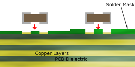
IPC-SM-840C addresses the qualification and performance of permanent polymer solder mask, also called solder resist. The coating covers selected copper and laminate surfaces while leaving soldering pads, contacts and other specified areas exposed. It helps protect conductors and define where solder should wet during assembly.

The C revision dates to January 1996, with Amendment 1 issued in June 2000. It is a historical edition, so an existing drawing may name it even when a current material datasheet names a later revision. The standard concerns both material evaluation and the way the mask is used on a board. For example, a coating qualified on a test substrate still needs a suitable application process on the actual copper pattern.

What Do IPC SM 840 Classes T and H Mean?

Class T and Class H distinguish solder mask performance requirements by end-use reliability needs. Class T covers telecommunications and other high-performance commercial or industrial equipment. Class H addresses high-reliability applications where continued operation is critical. For drawings that specify IPC-SM-840C Class T or IPC SM 840C Class H, the required designation should carry through to the selected mask material.

Solder mask classApplication emphasisWhat to specify for your board
IPC SM 840 Class TLong service life in commercial and industrial electronicsRequired revision, compatible mask material and intended assembly conditions
IPC SM 840 Class HHigher assurance where uninterrupted operation is essentialRequired revision and class, with the qualification evidence applicable to that material and process

These letters describe the solder mask requirement. The finished PCB’s IPC-6012 Class 2 or Class 3 requirement is a separate specification covering the rigid board. Keeping both requirements explicit makes the intended coating performance and overall board quality clear.

Which Solder Mask Properties Affect PCB Reliability?

Adhesion, electrical insulation and resistance to processing exposure determine whether the coating can protect the circuit throughout manufacture and use. Colour and surface appearance matter for inspection and product presentation, but the functional properties are the basis for material selection.

Property groupWhat it addressesRelevance to the finished PCB
Adhesion and mechanical integrityBonding to the underlying surface; resistance to cracking or peelingMaintaining coverage around tracks, pads and machined edges
Electrical performanceDielectric strength and insulation resistanceHelping preserve insulation between neighbouring conductors
Soldering and chemical resistanceExposure to soldering heat, fluxes and process chemicalsKeeping the mask intact through board finishing and assembly
Environmental performanceMoisture exposure, thermal changes and electrochemical migrationMatching the material to the board’s service conditions
Cure and surface conditionDeveloped film properties and usable surface qualitySupporting consistent handling and subsequent processing

For our FR4 printed circuit boards, solder mask selection belongs alongside copper layout, surface finish and assembly requirements. A controller with exposed test points has different mask artwork needs from a densely populated communications board, even when both use the same laminate family.

How Does LPI Solder Mask Become a Protective Pattern?

Liquid photoimageable solder mask is applied as a coating and patterned by light exposure and development. A typical LPI soldermask process includes surface preparation, coating, preliminary drying, imaging, development and final cure. The result is a permanent film with openings matched to the circuit artwork.

Surface preparation supports adhesion; imaging and development define the openings; final cure develops the required film properties. Their combined effect explains why the material name alone is only part of the finished-board result. Dry-film photoimageable solder mask offers another material format, with different behaviour over the board’s raised copper features.

The phrase LDI vs LPI solder mask can cause confusion: LPI describes liquid photoimageable material, while laser direct imaging describes an imaging method. An appropriately formulated LPI material can be used with direct imaging. Material selection and imaging compatibility therefore need to be considered together.

What Is the Recommended Thickness for PCB Solder Masks?

The recommended finished thickness is material- and layout-specific; one universal value does not describe every PCB. Solder mask thickness affects protection over copper edges, available clearance and the local surface height around component pads. A patterned PCB is not flat: copper traces, planes and gaps create different coating conditions. Thickness over a conductor and thickness beside it may therefore differ.

Not-to-scale conceptual cross-section showing solder mask covering raised copper traces and laminate

An IPC SM 840 solder mask thickness requirement should identify the measurement location and the agreed finished-film requirement. A value measured over bare laminate is not directly interchangeable with one measured over copper. The material system, copper profile and circuit geometry determine the practical coating window.

This becomes especially relevant on our heavy copper PCBs: taller conductors make edge coverage and coating transitions more demanding. Providing the outer-layer copper requirement with the mask artwork allows these features to be considered together, rather than treating the mask as a uniform flat sheet.

Why Do Pad Openings and Mask Dams Matter?

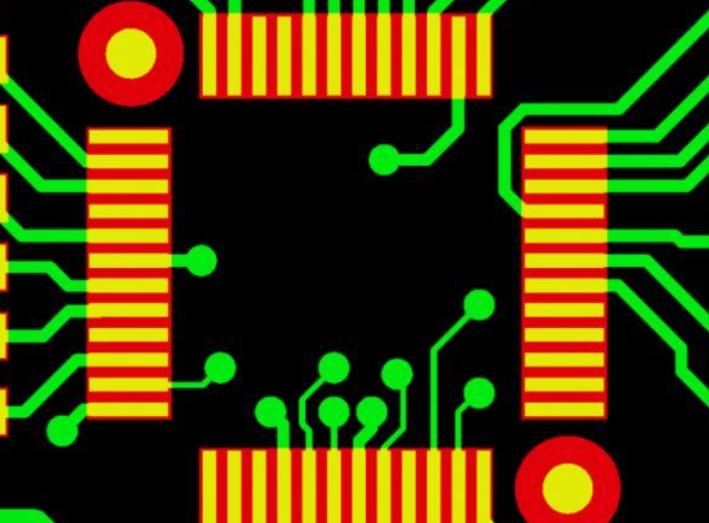
Pad openings expose the intended solderable surface, while a solder mask dam is the narrow strip of coating between adjacent openings. Registration is the alignment between the mask pattern and the copper pattern. Together, these features influence usable pad area and separation around fine-pitch components.

Conceptual top view of fine-pitch solder pads with separate openings and green solder mask dams

For our HDI boards, the pad pitch, opening size and achievable registration must work together. If a proposed dam is too narrow to manufacture consistently, the layout or opening strategy needs adjustment. The package’s land-pattern requirements remain important, particularly when choosing solder-mask-defined or non-solder-mask-defined pads.

Via tenting is a separate artwork choice: mask covers the via opening rather than filling the hole. Keep probe-access test points exposed, and specify via filling separately where that structure is required. These details help us preserve both assembly access and the intended coverage during DFM review.

How Do Surface Finish and Assembly Affect Mask Selection?

The mask must tolerate the selected board-finishing process and subsequent assembly exposure. ENIG, immersion tin and HASL use different chemical or thermal processing routes. Reflow, wave soldering and cleaning add further conditions after the bare board has been manufactured.

We offer finishes including ENIG, lead-free HASL, OSP, immersion silver and immersion tin. Sharing your intended finish and assembly route helps us discuss the appropriate board construction and mask compatibility. For a mixed SMT and through-hole assembly, the total processing sequence matters more than considering one reflow pass in isolation.

Mask colour can also affect imaging and cure settings within a material family. A green-to-black or green-to-white change is therefore a material/process choice as well as a cosmetic one. Its effect on fine features should be reviewed with the board requirements.

Solder Mask vs Conformal Coating: What Is the Difference?

Solder mask protects selected areas of the bare PCB and defines soldering openings. Conformal coating is normally applied after assembly to protect the populated board from its environment. They occupy different places in the build and can be used together.

Conceptual comparison of solder mask on a bare PCB and a translucent protective coating over an assembled circuit

For an industrial sensor exposed to humidity, the bare board may use solder mask while the completed assembly receives a compatible conformal coating. Connectors and test interfaces can require selective exclusion from that later coating. Adhesion between the two coatings and compatibility with cleaning residues become part of the assembly design.

Our PCB and PCBA services let you discuss bare-board manufacture and assembly as a connected project. Where additional protective coating is required, include that requirement with the assembly information so the intended materials and exposed areas are clear.

IPC SM 840 Latest Version: Is Revision C Still Current?

No. As of September 2026, the IPC document revision table lists revision E, issued in December 2010, after revision D from April 2007. C remains relevant to legacy specifications, but new project documentation should identify the edition actually required.

In the IPC SM 840 family, IPC SM 840C was followed by IPC SM 840D and IPC SM 840E. Revision E’s scope includes flexible cover materials as well as permanent solder mask. The revision letter therefore conveys technical scope, not merely a newer publication date.

If your drawing calls for C and the proposed mask documentation references E, send both with the project files. We can discuss the specified material and manufacturing route with you; any change to the drawing’s requirement should be agreed before production. The selected edition and class provide a clearer requirement than simply writing “IPC solder mask.”

How Can We Support Your PCB Solder Mask Requirements?

We combine PCB manufacturing, DFM support and assembly services, helping you match the solder mask pattern to the actual circuit. Our FR4 capability extends to 32 layers, and our HDI capability includes minimum line/space down to 2/2 mil, subject to materials, stack-up, board dimensions and engineering review. These are circuit-fabrication capabilities; the mask opening and dam requirements are reviewed separately.

For a board specified to IPC-SM-840C, send the Gerber files, fabrication drawing, required class, mask colour, surface finish and any critical pad or via details. Add assembly files when PCB assembly is part of the project. Contact our team at sales@bestpcbs.com or through our PCB manufacturing enquiry page to discuss your board.


You may also like

PCB Peelable Solder Mask: When to Use It and How to Specify It
Saturday, September 5th, 2026
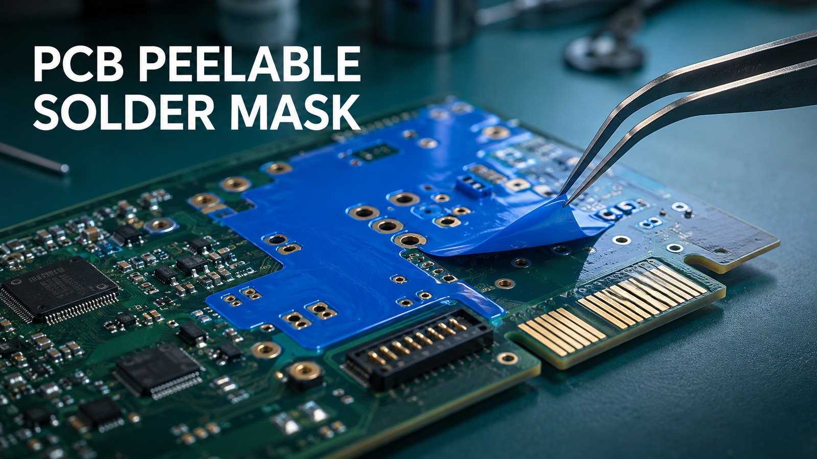
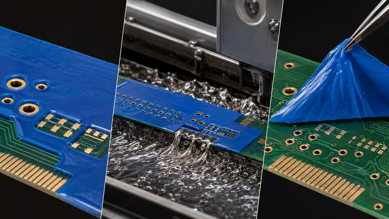
PCB peelable solder mask protecting selected through-holes and contacts before removal
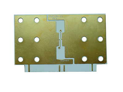
Peelable solder mask temporarily protects selected PCB features during assembly or coating, then is removed.

PCB peelable solder mask is a temporary masking material used to keep solder, flux, cleaning fluid or conformal coating away from selected holes, contacts and component areas. Unlike the permanent solder mask that remains on a finished PCB, the temporary film is applied for a defined process step and peeled away afterward.

It is useful only when the material, coverage, cure condition and removal plan match the assembly process. A vague fabrication note such as “add blue mask” is not enough: the supplier needs a marked layer, the protected features, the process exposure and the acceptance condition. This guide explains how to make that decision and prepare a quote-ready package.

What Is PCB Peelable Solder Mask?

Peelable mask is a removable process aid, not the PCB’s permanent dielectric coating. It is commonly supplied as a viscous liquid that is placed over selected areas, cured into a flexible film, exposed to the intended process and removed manually. Product chemistry and processing windows differ, so the selected material’s current technical data sheet controls.

The distinction matters at purchase order review. IPC-SM-840 addresses permanent solder mask and flexible cover materials; it should not be used as a blanket qualification statement for every temporary peelable compound. Define temporary masking as its own fabrication or assembly requirement, with a named purpose and an agreed acceptance check.

Layer or material Purpose End condition
Permanent solder mask Insulates and protects the finished PCB surface while exposing intended pads Remains on the board
Peelable temporary mask Blocks solder, flux or coating from selected zones during a process step Removed after the defined operation
Coverlay Protects flexible-circuit conductors and defines openings Remains as part of the FPC
Assembly tape or fixture Provides temporary mechanical masking or support Removed or reused according to the process

When Should You Use Peelable Mask on a PCB?

Use it when selected features must stay free of solder or coating while nearby areas go through the same operation. The strongest use cases have a clear protected zone, a compatible material and an accessible peel path.

  • Keep selected plated through-holes open during wave soldering for a later connector or mechanical assembly.
  • Protect edge contacts, test points, pins or terminals from solder contact.
  • Mask connectors and keep-out areas during spray, brush or dip conformal coating when the chosen product supports that exposure.
  • Temporarily cover a local area during cleaning or another documented assembly operation.
  • Reduce manual taping where repeatable dispensed or screened coverage is practical.

Do not choose it merely because it is removable. Very small, tightly packed or inaccessible zones may be difficult to coat consistently and harder to peel without fragments. High-temperature dwell, aggressive chemicals, bare-metal compatibility and cleanliness requirements must be checked against the exact product and process.

Peelable Mask vs Tape, Washable Mask and Permanent Solder Mask

The best option is the one that protects the feature through the process and can be removed without creating a new defect. Geometry, volume, temperature, chemistry and cleanliness usually decide the choice.

Option Good fit Risk to check
Peelable mask Irregular groups of holes or contacts; repeatable local coverage Minimum film body, complete cure, peel access and fragment control
High-temperature tape Simple edges or flat shapes; low-volume manual work Labor, edge leakage, adhesive residue and placement variation
Washable mask Processes with a validated compatible wash step Complete dissolution, wash chemistry and trapped residue
Reusable fixture or pallet Stable, repeated production with suitable board geometry Tooling cost, board support, clearances and revision control
Permanent solder mask Normal long-term surface protection and pad definition It cannot serve as a removable post-process mask

For a related overview of surface-protection choices, see the guide to solder mask on a PCB. For board purchasing, the broader PCB fabrication specifications checklist helps connect the mask note to the full build package.

Which PCB Areas Should Be Protected?

Mark only the features that must remain untouched by the next operation, then include enough surrounding area to form a continuous removable film. Protection zones often include through-holes reserved for a later insertion step, gold fingers, connectors, test points, terminals or coating keep-outs.

Review the zone against both sides of the board. A mask covering a hole on one side may not prevent ingress from the opposite side unless the application method and coverage are designed for it. Also check nearby solder joints, small components and board edges so the cured film can be gripped and peeled without stressing hardware.
  1. Identify the exact process the area must survive.
  2. Mark every protected feature on a dedicated drawing or unambiguous data layer.
  3. Define which board side receives the mask.
  4. Provide a clear boundary and any critical keep-out around adjacent pads or components.
  5. Confirm that the cured film has an accessible removal edge.

How Do Wave Soldering, Cleaning and Conformal Coating Affect the Choice?

A peelable mask must be selected for the complete exposure sequence, not for temperature alone. During wave soldering it may encounter preheat, flux, molten solder and cleaning. During conformal coating it may contact solvent or water-based chemistry and must resist coating ingress around the protected feature.

Manufacturer data illustrates why a generic number is risky. Techspray’s WonderMASK P documentation gives product-specific cure, thickness and wave-solder limits, while MG Chemicals 862 lists its own application and cure parameters. Those values describe those named products; they are not universal PCB design rules. The contract manufacturer must confirm the actual material, application method and validated process window.

Surface finish also matters because the protected feature may be bare copper, plated metal, a soldered surface or a gold contact. Request compatibility confirmation for the actual finish rather than assuming all peelable masks behave alike. The selection of the exposed finish itself can be reviewed separately in the PCB surface-finish selection guide.

How Should Peelable Solder Mask Be Shown in Gerber Data and Drawings?

Create a dedicated, clearly named temporary-mask layer and repeat its purpose in the fabrication or assembly drawing. Do not rely on color alone, a screenshot or a filename such as “blue glue” without a legend. The manufacturer must know whether filled shapes indicate covered areas or openings.

  1. Name the layer, for example, TOP_PEELABLE_MASK or BOTTOM_TEMP_MASK.
  2. State the polarity: “filled geometry equals mask coverage.”
  3. Identify the operation: wave solder protection, conformal-coating keep-out or another defined step.
  4. Call out the board side, protected feature and any critical boundary tolerance.
  5. State that the mask is temporary and must be removed after the specified operation.
  6. Define the post-removal acceptance condition: no unintended solder/coating on protected features, no visible mask fragments, and no damage to pads, finish or components.

Include a reference image only as a communication aid; released manufacturing data must remain authoritative. If Gerber naming or polarity is unclear, expect a DFM question before production.

Which Material and Process Limits Must the Supplier Confirm?

Ask the supplier to identify the exact temporary mask and confirm it against the board finish and assembly route. Evidence should be marked as verified, to be confirmed or unavailable. Do not turn an open capability question into a public claim.

  • Product name, revision of technical data sheet and shelf-life control.
  • Compatibility with copper, gold, silver, solder, OSP or other exposed finish in the protected zone.
  • Application method: hand dispense, template, pneumatic or robotic placement.
  • Target film build and minimum practical geometry for a continuous peel.
  • Cure condition, maximum process temperature and exposure time.
  • Resistance to the actual flux, cleaner and conformal-coating chemistry.
  • Removal method, peel access and residue/fragment inspection.
  • First-article evidence before volume production.

For quotation, treat this as a capability-to-be-confirmed item. Board type, factory route, selected material and the original process record must all be checked before a supplier commits to a production value.

Three-stage PCB peelable solder mask process showing protection, wave soldering and clean removal
A robust plan covers application, process exposure and complete removal—not just the mask artwork.

What Causes Lifting, Leakage, Tearing or Residue?

Most failures trace to surface condition, weak geometry, incomplete or excessive cure, incompatible chemistry or an uncontrolled removal step. Diagnose the mechanism instead of simply adding more material.

Symptom Likely questions Control
Edge lifting Was the surface contaminated? Was the film fully formed at the edge? Clean surface, validate application and inspect before exposure
Solder or coating leakage Was the boundary continuous? Did the process attack the mask? Confirm coverage and chemistry with a first article
Film tears during peeling Was it too thin, over-cured or trapped around geometry? Use a validated film body and accessible peel path
Fragments remain in holes Were holes bridged or filled in a way that prevents one-piece removal? Inspect both sides and use magnification where needed
Residue or finish change Is the exact material compatible with the surface and cleaner? Approve the named material and verify after removal

A preproduction board is valuable when the geometry is new, the protected finish is sensitive or the mask will see multiple chemical steps. Record the applied condition and removal result so production is not dependent on operator memory.

How Should Peelable Mask Be Inspected and Removed?

Inspect coverage before the protected operation and inspect cleanliness and feature condition after removal. The film should be removed using the method approved for the material, typically with a controlled manual peel. Do not assume a peelable mask will dissolve in the cleaning process.

  • Before processing: verify the correct board side, all marked zones, continuous edges and no interference with intended solder joints.
  • After processing: allow the board and coating, where applicable, to reach the approved removal condition.
  • Peel without levering against small components, pads or fragile flex areas.
  • Inspect holes, corners and narrow gaps for remnants.
  • Verify protected contacts remain free of unintended solder or coating.
  • Check that the surface finish, permanent solder mask and nearby components are undamaged.
  • Record first-article photographs when the mask is a critical process characteristic.

If the user intent is specifically “how to remove solder mask from PCB,” first distinguish temporary peelable mask from permanent LPI solder mask. Permanent solder mask removal is a different rework operation and may damage copper or change the board’s insulation and reliability.

What Changes Peelable-Mask Cost and Lead Time?

Cost is driven mainly by protected-area complexity, application method, inspection effort and whether the process is already validated. A few accessible holes may be straightforward; many small islands, both-side coverage, tight component clearances or repeated coat/cure cycles add labor and risk.

Lead time can increase when the material must be sourced, the drawing is ambiguous, a first article is required, or compatibility testing is needed for a special finish, cleaner or coating. Quantity changes the economic choice: manual masking can fit prototypes, while recurring production may justify a template, controlled dispensing program or solder pallet.

Ask suppliers to separate non-recurring setup from per-board masking and inspection. That makes quote comparisons more meaningful than a single total price with different assumptions hidden inside it.

What Should You Send in a Peelable-Mask RFQ?

A quote-ready package tells the supplier what to protect, what the mask must survive and how the result will be accepted. Send:

  • Gerber or ODB++ files, drill data and fabrication drawing.
  • A dedicated top and/or bottom temporary-mask layer with stated polarity.
  • PCB stackup, material, thickness, copper and surface finish.
  • Assembly drawing, BOM and CPL when the board will also be assembled.
  • Wave-solder profile or other expected temperature exposure.
  • Flux, cleaning and conformal-coating details where relevant.
  • Quantity, prototype/production stage and target delivery date.
  • Required first-article photographs, inspection report or sample approval.
  • Post-removal acceptance criteria and any cleanliness requirement.

For a complete manufacturing handoff, pair this with the site’s PCB DFM guide. A supplier can then review mask feasibility together with the board outline, holes, finish, assembly sequence and inspection plan.

FAQ About PCB Peelable Solder Mask

Is peelable solder mask permanent?

No. It is a temporary process material intended to be removed after the specified soldering, cleaning or coating operation. Permanent PCB solder mask remains on the finished board.
Why is peelable solder mask often blue or pink?

Color helps operators see coverage and, for some products, may indicate curing progress. Color alone does not identify chemistry or performance, so use the product name and current TDS.

Can peelable mask protect plated through-holes during wave soldering?

Yes, this is a common application when the selected product and coverage are validated for the wave process. Both-side access, film continuity and post-process removal still require review.

Can it protect gold fingers and contacts?

Some named products are documented for contacts or gold fingers, but compatibility must be confirmed for the exact finish, material and exposure sequence.

Is peelable mask the same as coverlay?

No. Coverlay is a permanent protective layer used on flexible circuits. Peelable mask is temporary and is removed after its process function is complete.

Can I specify only “blue mask” on the drawing?

No. State that it is temporary peelable mask, define the covered geometry and polarity, identify the board side and operation, and specify removal and acceptance requirements.

How thick should peelable solder mask be?

There is no single universal value. Each material has a product-specific recommended film build, and the practical geometry also depends on application and removal. Use the selected product’s TDS and supplier approval.

Does peelable mask leave residue?

A suitable, correctly processed product is intended to remove cleanly, but residue or fragments can occur if chemistry, cure, surface condition or geometry is wrong. Post-removal inspection is necessary.

How is temporary peelable mask removed from a PCB?

After the approved process and cooling or coating condition, it is normally lifted and peeled manually according to the material instructions. Inspect holes and tight corners for remnants.

Should the first production build include a mask sample?

Yes when the geometry, finish, chemistry or thermal route is new or critical. A first article can confirm coverage, survival, removal and the protected-feature acceptance condition before volume production.

Need a PCB quote with temporary peelable masking?

Send EBest Circuit your Gerber/ODB++ files, peelable-mask layer, surface finish, process profile, quantity and acceptance requirements. We will review the data and confirm the applicable manufacturing route before quotation.

Send your peelable-mask RFQ package | Contact EBest Circuit

You may also like

What is the solder mask? PCB basic information
Wednesday, February 19th, 2025

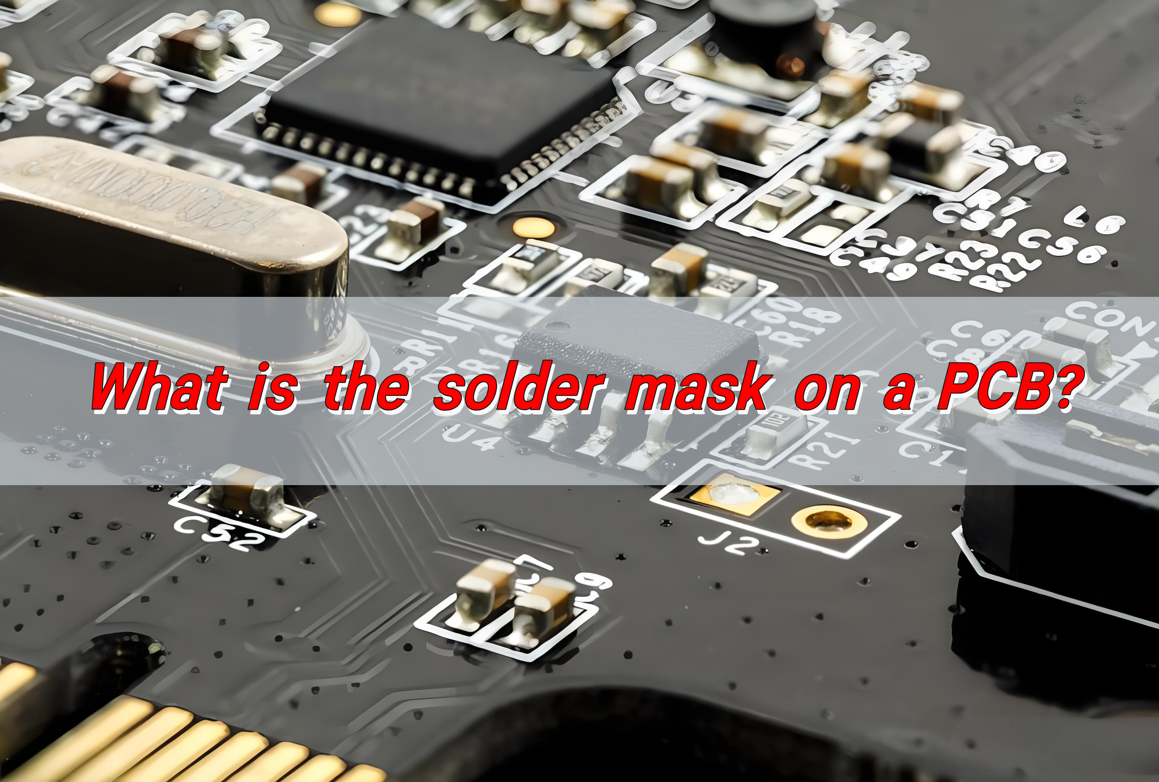
What is a solder mask? The solder mask on the PCB is a special coating covering the surface of the circuit board, usually composed of polymer resins, pigments and other materials. It is used to prevent solder from flowing into non-soldering areas during soldering, avoid short circuits, and protect copper lines from oxidation and environmental erosion.

What is the solder mask on a PCB?

What is solder mask layer on pcb?

The solder mask layer is a thin polymer layer applied to the surface of a PCB to protect the copper traces from exposure to air, moisture, and solder during assembly. It is typically applied as a liquid and then cured to create a durable, insulating coating.

This layer ensures that solder only adheres to designated areas, such as component pads, while preventing unintentional connections that can cause electrical failures.

Most PCBs feature a solder mask on both sides, covering all traces except for the exposed pads where components will be soldered. The mask enhances the board’s mechanical strength, providing extra durability against physical damage.

What is a solder mask used for?

A solder mask serves multiple functions in PCB manufacturing and assembly, including:

What is the solder mask on a PCB?
  • Prevents Solder Bridging – Stops accidental solder connections between closely spaced components.
  • Protects Copper Traces – Shields against oxidation and environmental damage.
  • Improves Electrical Insulation – Reduces the risk of unintended electrical contact between conductive traces.
  • Enhances PCB Durability – Adds a layer of mechanical strength, preventing wear and tear.
  • Aesthetic Enhancement – Gives PCBs a smooth, uniform finish and a professional appearance.

By preventing shorts and increasing reliability, the solder mask plays an essential role in producing high-performance circuit boards.

What is the standard thickness of a solder mask layer?

The thickness of a solder mask depends on the manufacturing method and the type of PCB. The most common solder mask thickness values are:

  • Liquid Photoimageable (LPI) Solder Mask: 0.7 to 1.5 mils (18-38 microns)
  • Dry Film Solder Mask: 0.5 to 1.2 mils (12-30 microns)
  • UV Curable Solder Mask: 0.2 to 1.0 mils (5-25 microns)

A well-applied solder mask ensures proper adhesion and durability without interfering with PCB functionality.

How to apply solder mask to a pcb?

The solder mask application process follows precise steps to ensure uniform coverage and proper curing:

What is the solder mask on a PCB?
  • Surface Preparation – The PCB is cleaned to remove dust, oils, and oxidation.
  • Curtain Coating – Ideal for high-volume production.
  • Spray Coating – Suitable for complex multilayer boards.
  • Pre-baking – The board is partially cured to enhance adhesion.
  • UV Exposure – The solder mask is exposed to UV light through a photomask to define areas where it should remain.
  • Development & Cleaning – Uncured mask material is removed to reveal solder pads.
  • Final Curing – The PCB undergoes heat curing for maximum durability.

This process ensures a strong, long-lasting solder mask layer that can withstand harsh conditions.

How long does it take for solder mask to cure?

Curing time depends on the method used:

  • UV Curing: A few minutes with high-intensity UV exposure.
  • Thermal Curing: 30-60 minutes at 150°C (302°F) for enhanced durability.
  • Combination Curing: UV exposure followed by thermal curing for optimal strength.

Proper curing is crucial to prevent defects like delamination, peeling, or cracking.

Does solder mask color matter?

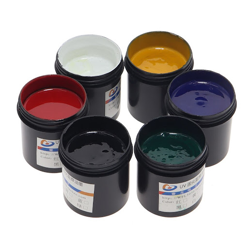
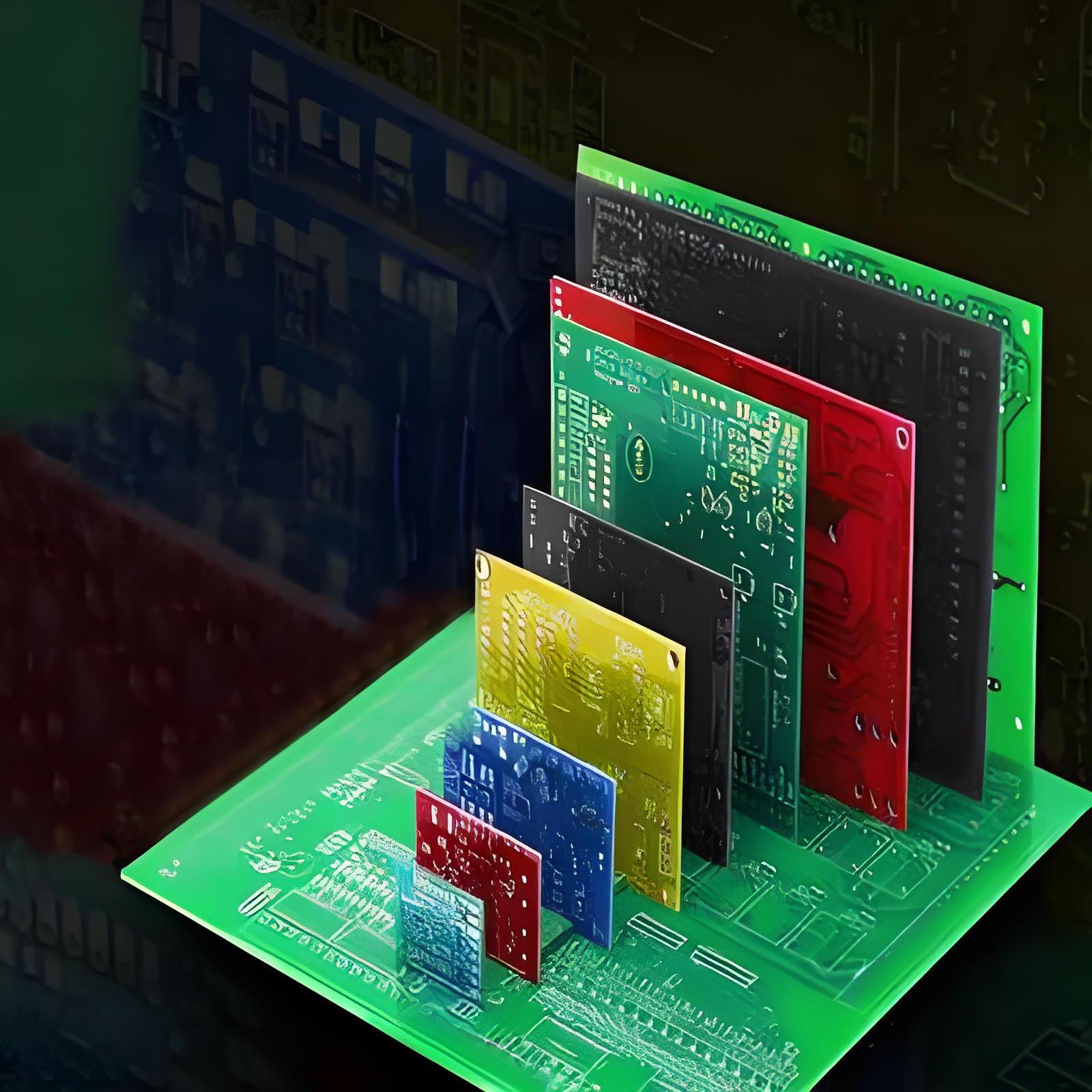
The color of a solder mask does not affect PCB performance, but it can impact visibility, aesthetics, and inspection efficiency. Common colors include:

What is the solder mask on a PCB?
  • Green – The industry standard for optimal contrast and easy inspection.
  • Blue – Provides high contrast with white silkscreen text.
  • Red – Used for high-end or custom branding.
  • Black – Reduces light reflection but makes defect detection harder.

While color selection is mostly aesthetic, certain colors may aid in automated optical inspection (AOI) processes.

Why is most solder mask green?

Green solder mask is widely used due to:

  • Best Visibility for AOI – The contrast makes defect detection easier.
  • Industry Standardization – Manufacturers are optimized for green solder mask production.
  • High Durability – Green solder masks tend to have better adhesion and chemical resistance.

However, manufacturers can produce PCBs with different solder mask colors based on specific project needs.

What is the difference between blue and green solder masks?

The key differences between blue and green solder masks are:

  • Green – Best for automated inspection, high contrast, and industry standard.
  • Blue – Vibrant appearance but slightly harder for AOI systems to detect defects.

Both options provide reliable protection, and the choice depends on aesthetic and inspection needs.

What is the difference between solder mask and solder paste?

Solder mask and solder paste serve different purposes in PCB assembly:

  • Solder Mask – A permanent protective coating that prevents unintended soldering and oxidation.
  • Solder Paste – A temporary material containing metal particles and flux, used to attach components before reflow soldering.

Both are essential for high-quality PCB production, but they are applied at different stages.

Conclusion:

In summary, the solder mask plays a critical role in ensuring the longevity and reliability of a PCB. It protects the copper traces, prevents soldering errors, and improves overall circuit board performance.

At EBest Circuit (Best Technology), we are committed to delivering high-quality PCBs, with precise solder mask application, to meet your specific needs. Contact us today for customized PCB solutions that will elevate your product’s performance. Email: sales@bestpcbs.com

You may also like

How to Assemble Own PCB Solder Mask?
Tuesday, December 3rd, 2024

What Is Solder Mask?

Solder mask also known as S/M, it is a protective layer applied to a printed circuit board (PCB) to shield the copper traces from oxidation and environmental damage. It serves as an insulator between the conductive areas of the PCB and the external environment, preventing unwanted electrical contact. This layer is typically applied after the copper traces are etched and before the components are mounted.

In addition to protection, the solder mask also provides insulation between adjacent copper traces, reducing the risk of short circuits. It allows manufacturers to design high-density boards where components are placed closely together. The solder mask is essential for achieving a clean, functional, and professional-looking PCB.

How to Assemble Own PCB Solder Mask?

Is Solder Mask Necessary?

In professional PCB manufacturing, a solder mask is more than just a protective layer—it’s a necessity. While some DIY enthusiasts might skip it, especially for simple projects, it plays a critical role in ensuring the board’s functionality and longevity. It’s purposes are mainly including:

  • Prevents Short Circuits: By covering the copper traces and exposing only the necessary pads, it minimizes the risk of solder bridges between components. This is especially important for boards with tight spacing.
  • Increases Durability: The solder mask acts as a barrier against moisture, dust, and chemicals that could corrode the copper traces.
  • Improves Aesthetic Appeal: A board with a solder mask looks clean, organized, and professional. This is particularly important for commercial products where appearance matters.
  • Facilitates Easier Soldering: The mask helps guide solder to the right spots, reducing the chances of errors during assembly.

While it’s technically possible to assemble a PCB without a solder mask, the risks outweigh the benefits. Without it, the board is more vulnerable to environmental damage and soldering mistakes.

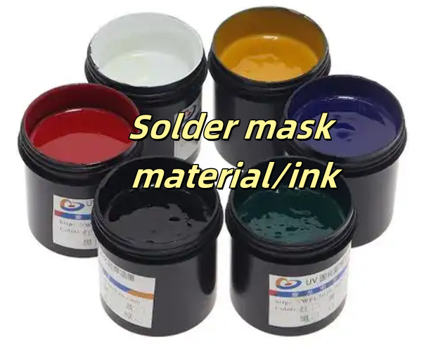
PCB Solder Mask Material / Solder Mask Ink

The type of solder mask material you choose can significantly impact the PCB’s performance and durability. Each material type has specific characteristics that make it suitable for different applications.

How to Assemble Own PCB Solder Mask?

Epoxy Liquid Solder Mask:

This is one of the oldest and most cost-effective types of solder masks. It’s applied as a liquid and cured to form a protective layer. While it provides decent protection, its precision is not as high as more modern materials. It’s suitable for simpler designs or single-layer boards.

Liquid Photoimageable (LPI) Solder Mask:

LPI solder mask is the most commonly used type in modern PCB manufacturing. It’s applied as a liquid and then exposed to UV light through a photomask, which defines the areas to be covered. This method offers excellent precision and is ideal for high-density, multi-layer PCBs.

Dry Film Solder Mask:

This type is applied as a film and laminated onto the PCB surface. It’s often used in high-end applications where uniformity and precision are critical. Dry film masks provide better coverage and are less prone to defects compared to liquid-based masks.

UV-Curable Solder Mask:

This is popular among DIY enthusiasts because it’s easy to apply and cures quickly under UV light. While it doesn’t offer the same level of durability as industrial-grade masks, it’s sufficient for small-scale projects.

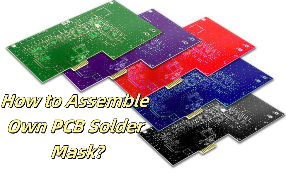
Solder Mask Colors

The color of the solder mask might seem like a purely aesthetic choice, but it can also affect the board’s usability during assembly and inspection.

  • Green

Green is the industry standard due to its high contrast with the white silkscreen layer and the copper traces beneath. This contrast makes it easier to inspect for defects and errors.

  • Red

Red solder masks offer a bold appearance and are often used for specialized or high-end boards. The contrast is not as high as green, but it’s still sufficient for inspection purposes.

  • Blue

Blue masks are commonly used in consumer electronics. They provide a unique look and offer good contrast with the copper traces, making inspection relatively easy.

  • White

White solder masks are often used in LED applications because they reflect light effectively. However, they can make inspection more challenging since the contrast with the silkscreen is low.

  • Black

Black masks give a sleek, professional look but are the hardest to inspect visually. They’re often used in high-end consumer products where appearance is a priority.

Advantages of Solder Mask

Adding a solder mask to your PCB offers several benefits that go beyond aesthetics. Here’s a closer look at its advantages:

  • Solder masks act as a barrier between adjacent pads, reducing the chances of accidental solder bridges during assembly.
  • The mask shields the copper traces from moisture, dust, and other contaminants, preventing oxidation and corrosion.
  • Some solder masks are designed to withstand high temperatures, making them suitable for applications where the board is exposed to heat during operation.
  • A well-applied solder mask gives the PCB a clean and professional look, which is essential for commercial products.
  • By exposing only the necessary pads and vias, the solder mask guides the solder to the right spots, smooth the assembly process and reducing the chances of errors.

What Is the Minimum Solder Mask Gap in PCB?

The solder mask gap is the distance between two adjacent exposed copper areas on the PCB. For most PCBs, the minimum solder mask gap is between 0.1 mm and 0.15 mm. This is sufficient for standard designs with moderate trace density. But in high-density designs, where traces and pads are closely packed, the gap might need to be as small as 0.05 mm. However, this requires precise manufacturing techniques to avoid defects.

How to Assemble Own PCB Solder Mask?

Some applications may have specific requirements for solder mask gaps, depending on the voltage and current levels involved. It’s essential to consult with your manufacturer to determine the optimal gap for your design. If you don’t have a reliable PCB manufacturer, EBest Circuit (Best Technology) is your go-to choice.

How to Add Solder Mask to PCB?

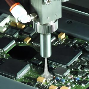
The process of applying a solder mask involves several steps, let me explain it for you:

1. Clean the PCB Surface

    Before applying the solder mask, ensure the PCB surface is clean and free of dust, grease, or oxidation. This step is key to keep proper adhesion and reduces the risk of defects during solder mask applying.

    2. Apply the Solder Mask

    Depending on the type of mask, you can apply it using a brush, spray, or lamination method. For DIY projects, UV-curable solder masks are often the easiest to work with.

    3. Expose to UV Light

    If you’re using a UV-curable mask, place the PCB under UV light for a specified period to harden the mask.

    4. Develop the Mask

    After exposure, remove the unexposed areas to reveal the pads and vias that need to remain uncovered.

    5. Cure the Mask

    Finally, bake the PCB in an oven to fully cure the solder mask and ensure it adheres well to the board.
    What Happens If You Solder Without a Mask?

    Without solder mask, PCB will have the following problems during soldering:

    • Poor electrical performance

    No solder bridge will lead to short circuit between the pad on the circuit board and the surrounding wires and components, thus affecting the stability and reliability of the circuit board.

    • Reduced reliability

    The pad may be accidentally welded, resulting in component damage or failure. In addition, circuit boards without solder bridges are susceptible to dust, dirt, and moisture, which affects the life and stability of the board.
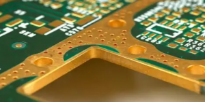
    • Increased manufacturing cost

    ‌The absence of solder  mask bridges increases manufacturing costs as manufacturers need to be more careful in the production process to avoid welding errors and other problems.‌

    Solder Mask Alternatives

    If you don’t have access to a traditional solder mask, here are some alternatives:

    1. Kapton Tape – A heat-resistant tape that can act as a temporary solder mask.
    2. Nail Polish – Some DIY enthusiasts use nail polish as a makeshift solder mask, though it may not be as durable.
    3. UV-Curable Ink – A popular choice for DIY PCBs, offering good protection and ease of application.

    Each alternative has its limitations but can be useful for specific applications.

    With over 18 years as an industry leader, EBest Circuit (Best Technology) is one of the most experienced PCB and PCB assembly manufacturer in China. Our highly specialized not only in quick-turn PCB prototype and PCB assembly, but also medium and small volume PCB fabrication. We can provide solder mask on your PCBs, and we will try our best to meet the demands of the solder mask.

    If you have any questions, please feel free to contact us with sales@bestpcbs.com, we will be happy to help you.

    You may also like

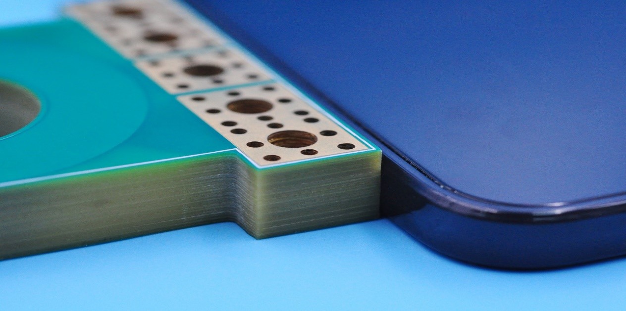
    Key Challenges in Solder Mask Printing for Heavy Copper PCBs
    Tuesday, May 23rd, 2023

    As the demand for higher power and miniaturization of electronics increases, so does the need for Heavy Copper Printed Circuit Boards (PCBs). From our last blog – Why choose Heavy Copper PCB for your High Current Project, we know the heavy copper PCBs are defined as those with copper thicknesses greater than 3 oz. These PCBs are designed to withstand high current and thermal loads, making them suitable for power electronics applications. However, the increased copper thickness also poses challenges during the solder mask printing process.

    (16_layers_heavy_copper_PCB_with_10oz_each_layer)

    Understanding solder mask

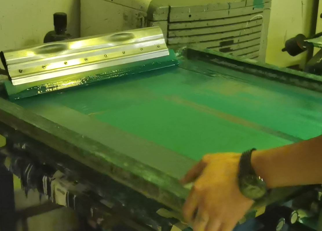
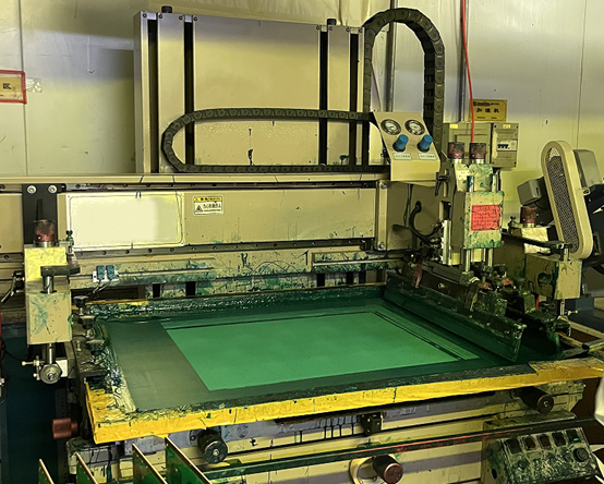
    Solder mask (short for S/M in the industry) is a protective coating applied to PCBs to prevent solder bridges and improve solder joint quality. The solder mask is coated to the PCB surface using a screen-printing process, where the desired pattern is created using a stencil and the solder mask ink is then deposited onto the PCB. The ink is then cured, either through heat baking or UV light, to form a solid coating.

    There are several types of solder mask materials available, including epoxy, acrylic, and liquid photo imageable (LPI) solder mask. Each type has its advantages and disadvantages, depending on the application requirements.

    The benefits of using solder mask in PCB manufacturing include increased reliability, improved solderability, and reduced risk of short circuits and corrosion. The solder mask we usually use is Taiyo, which has high reliability and excellent heat resistance.

    (Solder_mask_manually_printing)

    Challenges in solder mask printing of heavy copper PCBs

    While solder mask printing is a critical step in PCB manufacturing, the increased copper thickness in heavy copper PCBs presents several challenges for printing process as I mentioned before. It’s difficult to apply enough solder mask to cover thick copper pattern and base material with severe height difference.

    1. The high copper thickness and thermal conductivity of heavy copper PCBs make it difficult for the solder mask ink to adhere properly to the surface. This can result in insufficient coverage and registration accuracy, which can affect the overall quality and reliability of the PCB.

    2. The high copper thickness can cause stress on the solder mask, leading to mask cracking and peeling. The navigation mark on the substrate has specific ink thickness requirements due to limitations in the ink thickness that can be applied to the substrate. If the ink thickness on the substrate is too thick, it may result in solder resist cracks in the substrate position after the printed circuit board is soldered. This can occur during reflow soldering or thermal cycling, resulting in poor solder joint quality and reduced reliability.
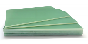
    3. The thick solder mask is also more difficult to exposure and develop. If the exposure energy is too weak or not enough, then some undercut problem may happen.

    How to overcome this challenge?

    To address these challenges, it is essential to choose the right solder mask materials and optimize the application process.

    • Choosing the right solder mask materials is crucial for ensuring proper adhesion and coverage on heavy copper PCBs. LPI solder mask is often preferred for heavy copper PCBs due to its excellent adhesion and thermal stability. However, epoxy and acrylic solder mask materials can also be used with proper surface preparation.
    • Optimizing the solder mask application process can also help address the challenges of heavy copper PCBs. This can include using a thinner stencil for improved registration accuracy and applying multiple coats of solder mask for better coverage. Advanced solder mask technology, such as laser direct imaging (LDI), can also help improve registration accuracy and reduce the risk of mask cracking and peeling.
    • Optimizing the printing process, now in EBest Circuit (Best Technology), we always make the substrate first, fill the substrate with the solder mask and then treat it as a normal PCB for normal printing solder mask.
    (Solder_mask_printing)

    If you are in the process of designing a complex multi-layer heavy copper PCB and are looking for a high-quality and experienced manufacturer, feel free to reach out to us at sales@bestpcbs.com, EBest Circuit (Best Technology) can support you by OEM and ODM service to ensure your design is cost-effective and can be easily manufactured.

    You may also like

    Differences Between Solder Mask and Solder Paste in PCB
    Wednesday, December 7th, 2022

    When it comes to solder mask and solder paste, there are some engineers confused about their functionalities and even most of laymen thought they are the same, this is not hypothetical, it is real that happened to me. So today let’s explain differences between Solder Mask and Solder Paste for you.

    Part 1: What is Solder Mask?

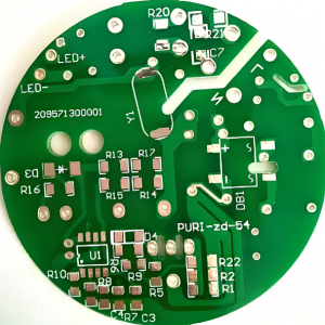
    If you had ever seen a printed circuit board, you may see there is a layer of green ink cover on the PCB surface while some orange-yellow areas didn’t cover by ink. In PCB industry, the green ink we called Solder Mask, or abbreviated as S/M, and exposed area is copper, they were leave as GND plane or soldering pads to mount electronic components.

    Solder mask is a liquid acrylic oligomer, which has variety of colors such as red, blue, green, white, black. Green is commonly used in the process of PCB manufacturing, so some professional engineers call it as green oil.

    Solder_mask

    Solder mask applied on the PCB designed as a protection layer to avoid oxidation, corrosion and other environmental impacts when they leave production line. In addition, solder mask between solder pads also can help to prevent forming to solder bridge when assembly.

    Below are some other functions of coating a layer solder mask:

    • Prevent physical line breaking of copper trace
    • Only weld in the area that must be soldered to avoid waste of soldering
    • Reduce copper pollution to soldering groove 
    • Prevent insulation deterioration and corrosion caused by dust, moisture and other external environmental factors 
    • With high insulation, so that the high-density circuit is possible

    Part 2: What is Solder Paste?

    Solder Paste also known as “Solder cream”, is a most important soldering material used in surface mount technology (SMT) process. Mainly function for soldering resistors, capacitors, ICs and other electronic components onto the PCB surface to form a permanent connection.

    The solder particles are a mixture of solder formed by mixing solder powder, flux and other surfactants and thixotropic. Traditionally this used to be tin and lead, but with the legislation has been introduced around the world, to only use lead free solders. These may be made from a variety of mixtures, EBest Circuit (Best Technology) commonly used is SAC305 which includes 96.5% tin, 0.5% copper and 3.0% silver, some manufacturers also use 99.7% tin and 0.3% copper, whereas there are other mixtures that include other metals including tin.

    Due to the role of solder paste in assembly, solder paste storage is extremely important. However, solder paste got into drying during storing became a common problem faced by most PCBA manufacturers, so How to solve solder paste dry problem is premier.

    Solder_paste

    Part 3: The Difference Between Solder Mask and Solder Paste

    1. Solder mask is a formal part of PCB, but solder paste ONLY for PCB assembly.
    2. Solder mask is not allowed on the solder pads while solder paste can be printed on the solder pads openings.
    3. Solder mask is used for applying solder mask ink, but solder paste is used for applying paste.
    4. Solder mask has many available colors, but paste mask visually gray.
    5. Solder mask is coating during PCB fabrication, but solder paste is printing when PCB assembly.

    With over 16 years in PCB industry, EBest Circuit (Best Technology) is one of the most reliable PCB and PCBA supplier in Asia, we commit to provide high quality products with excellent service before and after sales, to take care our customers wholeheartedly, and to treat customers’ business as ours. At the same time, we keep learning and continually to improve ourselves so that we can catch up the latest technology trend and provide better and better service for our customers.

    You may also like

    5 Views on Explaining Why the PCB Is Green
    Wednesday, January 2nd, 2019

    At the first sight, you will see that there is a layer of green oil on the PCB. It is called solder mask which is comprised of resin, talc and pigment. Of course, solder mask also has other colors, including red, yellow, black and so on, but green is the one that used the most widely.

    When it comes to the question like that “Why are the most of printed circuit boards are green?”, the engineers from EBest Circuit (Best Technology) with rich experience gave 5 points to explain it:

    1. There PCB is required to go through the exposure room with yellow light in some processes of fabrication and the visual effective in exposure room is better than the solder mask with other colors.

    What’s more, the PCB needs to coat tin, SMT and AOI testing during SMT soldering. All of these processes require optical position alignment and the green solder mask is better for the recognition of instruments.

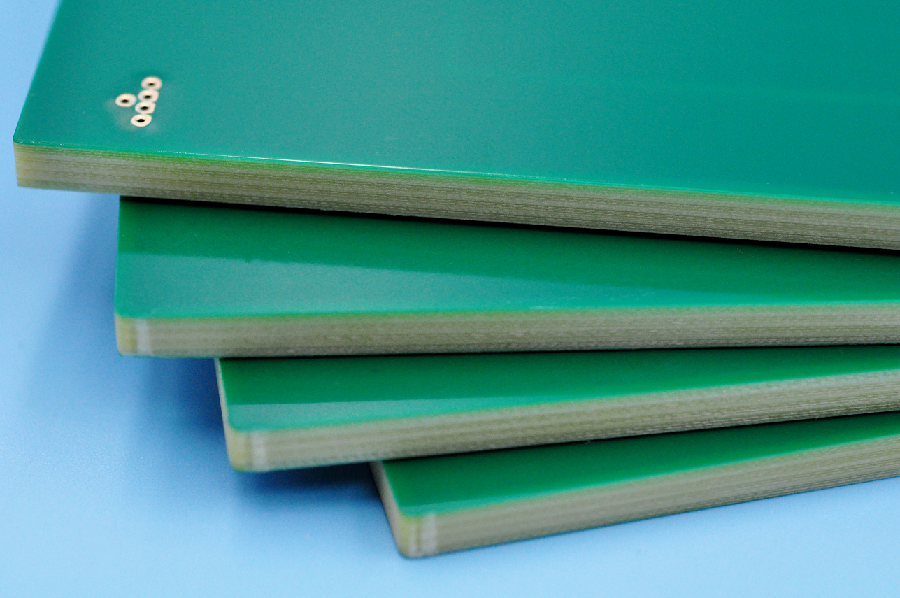
    PCB with green solder mask

    PCB with green solder mask

    2. Before the flying probe testing is applied widely, most of the wires on the PCB are relied on the naked eyes to inspect.It is very tired to detect the boards in strong light. If the rigid board is green, it will not do a lot harms to eyes.

    3. There are cobalt and carbon in  blue and black solder mask,which have a certain conductivity, so there is a risk of short circuit. However, the PCB with green oil will be more friendly to the environment. Because it will not release poisonous gases when use the printed circuit board in a high temperature environment.

    printed circuit board with green solder mask

    printed circuit board with green solder mask

    4. Since some famous brands began to use black solder mask in 2007, such as ASUS and Micro-Star and then people kept an eye on the colors of PCB.In this way, people gradually believe that PCBs with black solder mask means that the boards have high quality.After that, more and more PCB manufacturers started to apply black solder mask. NO one said that printed circuit boards with black solder mask are better than those with green solder mask.It is entirely due to the misleading caused by the famous brands using black solder mask to identify product positioning.

    5. There is no reason, just because of habit, so it has been used all the time.

    EBest Circuit (Best Technology) is the premier expert in PCB manufacture of electronics, brings a unique combination of technology and quality that offers a competitive supply of printed circuit board and PCBA. With high qualified engineers, we are able to help you find a PCB with high quality. To find out more, contact EBest Circuit (Best Technology) at 0755-29091601 or check the website: https://www.bestpcbs.com/

    You may also like