

Need reliable Rigid-Flex PCB Materials for compact electronics? Learn material types, stack-up choices, bend reliability, cost factors and supplier selection.
What Are Rigid-Flex PCB Materials?
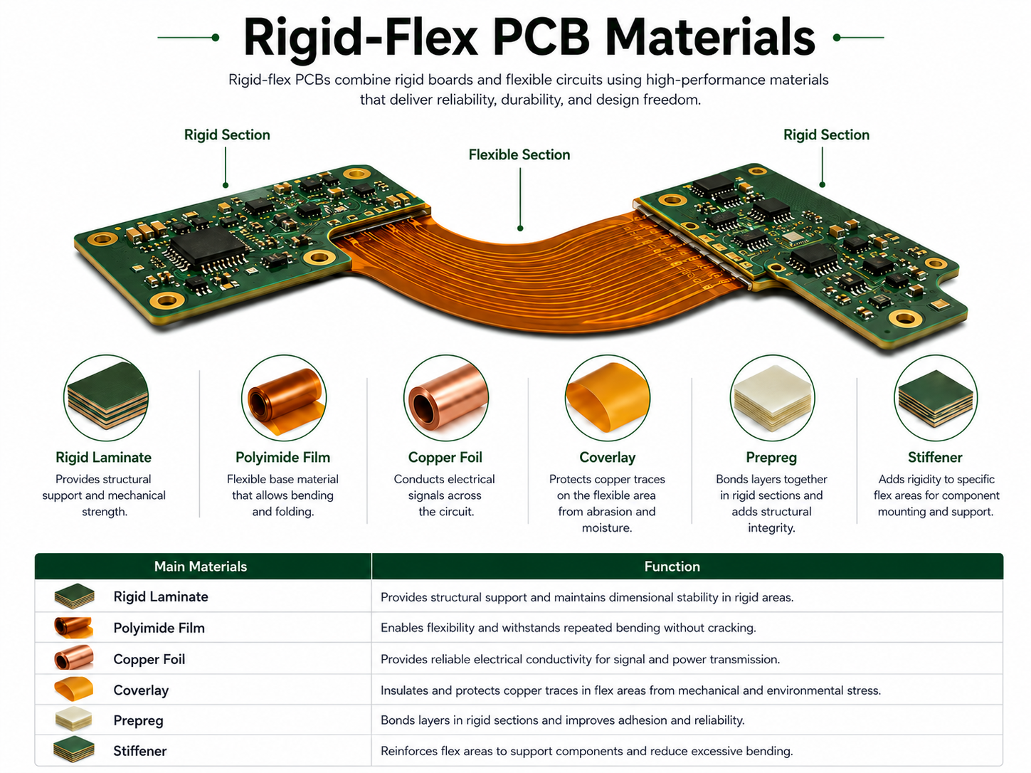
Rigid-Flex PCB Materials are the combined material systems used to build circuit boards with both rigid sections and flexible bending sections. These materials usually include rigid laminate, flexible polyimide film, copper foil, adhesive or adhesiveless flexible copper-clad laminate, prepreg, coverlay, bonding film and surface finish.
A rigid-flex PCB is not simply a rigid board connected to a flex cable. It is an integrated circuit structure where the flexible layers usually pass through or connect between rigid areas. This design helps reduce connectors, save internal space and improve long-term reliability in compact electronic products.
The material choice directly affects bending life, signal stability, heat resistance, copper adhesion, layer bonding and final assembly yield. If the wrong material is selected, the board may crack, delaminate, lose impedance control or fail during repeated bending.
Why Are Rigid-Flex PCB Materials Important?
Rigid-flex PCB materials are important because they decide whether the board can survive both mechanical movement and electrical operation. A rigid-flex design often appears in devices where space is limited, wiring must bend and long-term reliability is required.
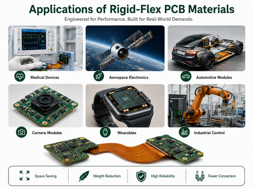
Common applications include medical devices, aerospace electronics, automotive modules, cameras, wearables, industrial sensors and portable electronics. These products often need smaller size, lighter weight and fewer connector points.
Industry guidance commonly refers to IPC-2223 for flexible and rigid-flex board design. IPC-2223 is a sectional design standard for flexible and rigid-flex printed boards, and it is often used together with qualification and performance standards for flex circuits.
For buyers, the material choice affects not only board price but also field reliability. A low-cost material stack-up may look acceptable at the quotation stage, but it can create hidden risks during bending, assembly or long-term thermal cycling.
How Do Rigid-Flex PCB Materials Work?
Rigid-flex PCB materials work by combining stable rigid areas with bendable flexible areas in one continuous circuit structure. The rigid parts support components, solder joints and mechanical assembly. The flexible parts allow folding, bending or connection between product sections.
The flexible section usually uses polyimide film because it offers strong heat resistance, dimensional stability and bending performance. Copper traces are laminated or bonded to the polyimide, then protected by coverlay or flexible solder mask.
The rigid section usually uses FR4, high-Tg FR4, halogen-free laminate, polyimide rigid laminate or high-frequency laminate, depending on electrical, thermal and reliability needs. Prepreg or bonding film connects the rigid and flexible structures during lamination.
What Are the Main Materials Used in Rigid-Flex PCB?
The main rigid-flex PCB materials include polyimide film, copper foil, FR4 laminate, high-Tg laminate, prepreg, adhesive, coverlay, stiffener and surface finish materials. Each material has a different function in the final board.
| Material | Function | Common Selection Point |
|---|---|---|
| Polyimide Film | Flexible dielectric base | Heat resistance and bending life |
| Copper Foil | Conductive circuit layer | Rolled annealed or electrodeposited copper |
| FR4 Laminate | Rigid area support | Cost, Tg, mechanical strength |
| High-Tg FR4 | Rigid area for thermal stress | Better heat resistance |
| Polyimide Laminate | High-reliability rigid section | Aerospace and harsh environments |
| Prepreg | Layer bonding in rigid area | Lamination compatibility |
| Adhesive | Bonds copper and dielectric | Flexibility and delamination risk |
| Coverlay | Protects flex copper traces | Bend durability and insulation |
| Flexible Solder Mask | Fine pattern protection | Detailed geometry |
| Stiffener | Reinforces connector or assembly area | PI, FR4 or stainless steel |
The best material system should be selected based on bend type, assembly method, thermal condition, electrical requirement and product lifetime.
What Flexible Core Materials Are Used in Rigid-Flex PCB?
The most common flexible core material is polyimide, often called PI. Polyimide is widely used because it can tolerate high soldering temperatures, repeated bending and harsh operating environments.
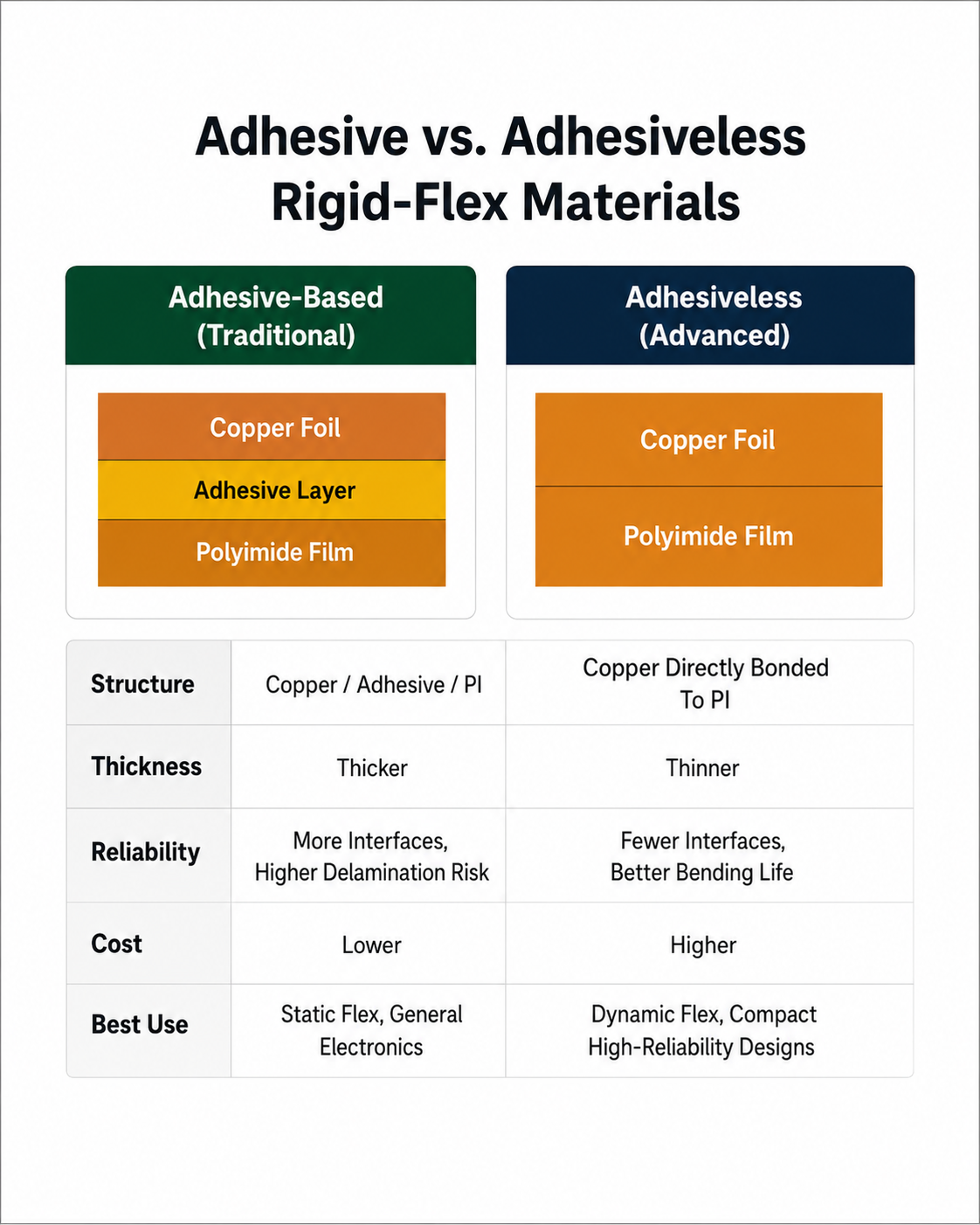
Flexible copper-clad laminate can be adhesive-based or adhesiveless. Adhesive-based material uses an adhesive layer between copper and polyimide. Adhesiveless material bonds copper directly to the film without a separate adhesive interface.
Adhesiveless construction can reduce total thickness and remove one interface where fatigue or delamination may start. This makes it useful for thin, high-reliability or dynamic-flex designs.
For most rigid-flex projects, the flexible material must be chosen early because it affects bend radius, copper fatigue, stack-up thickness and final reliability testing.
What Rigid Materials Are Used in Rigid-Flex PCB?
The rigid area of a rigid-flex PCB usually uses FR4, high-Tg FR4, halogen-free FR4, polyimide laminate or high-frequency laminate. The choice depends on cost, temperature, signal speed and mechanical requirements.
Standard FR4 is suitable for many commercial products where cost control is important. High-Tg FR4 is better for products that face higher soldering temperature, thermal cycling or long-term heat exposure.
Polyimide rigid laminate is often used in aerospace, defense, medical and high-reliability products. It costs more than FR4 but offers stronger thermal stability and better reliability under demanding conditions.
For RF or high-speed designs, engineers may choose special low-loss laminates in the rigid section. In this case, material matching between rigid and flexible areas becomes more important because impedance and dimensional stability must be controlled.
What Is Coverlay in Rigid-Flex PCB Materials?
Coverlay is a protective layer used over flexible copper traces. It is usually made from polyimide film with adhesive, and it protects the circuit from moisture, abrasion, handling damage and electrical shorting.
Coverlay is different from standard rigid PCB solder mask. It is more flexible and better suited for bending areas. Common coverlay structures may use 12.5–50 μm polyimide film with 12.5–25 μm adhesive, depending on design needs.
Coverlay is usually preferred in high-flex or harsh-use areas. Flexible solder mask may be used when the design needs finer openings or more detailed geometry, but it may not provide the same mechanical protection in repeated bending areas.
What Copper Foil Is Best for Rigid-Flex PCB Materials?
Copper foil is one of the most important rigid-flex PCB materials because it carries current and also survives bending stress. The two common choices are rolled annealed copper and electrodeposited copper.
Rolled annealed copper is often preferred for dynamic bending because its grain structure supports better flex life. Electrodeposited copper is widely used in standard PCB production and can be suitable for static bending or bend-to-install applications.
For high-reliability flexible sections, copper thickness should not be selected only by current capacity. Thicker copper can carry more current, but it also increases bending stress. Engineers must balance current load, bend radius, flex cycle requirement and trace width.
What Is the Difference Between Adhesive and Adhesiveless Rigid-Flex Materials?
Adhesive rigid-flex materials use an adhesive layer to bond copper to polyimide. This structure is common, cost-effective and widely available. It is suitable for many static-flex and commercial rigid-flex products.
Adhesiveless rigid-flex materials do not use a separate adhesive layer between copper and polyimide. This creates a thinner structure and may improve bending reliability because there is one less interface that can fail.
| Material Type | Main Advantage | Main Limitation | Best Use |
|---|---|---|---|
| Adhesive-Based Flex Material | Lower cost and wide availability | Thicker structure, more delamination risk | Static flex, general electronics |
| Adhesiveless Flex Material | Thinner, better reliability, improved bend life | Higher cost | Dynamic flex, compact and high-reliability designs |
If the product only bends during assembly, adhesive-based material may be enough. If the product bends repeatedly during use, adhesiveless material is often a better choice.
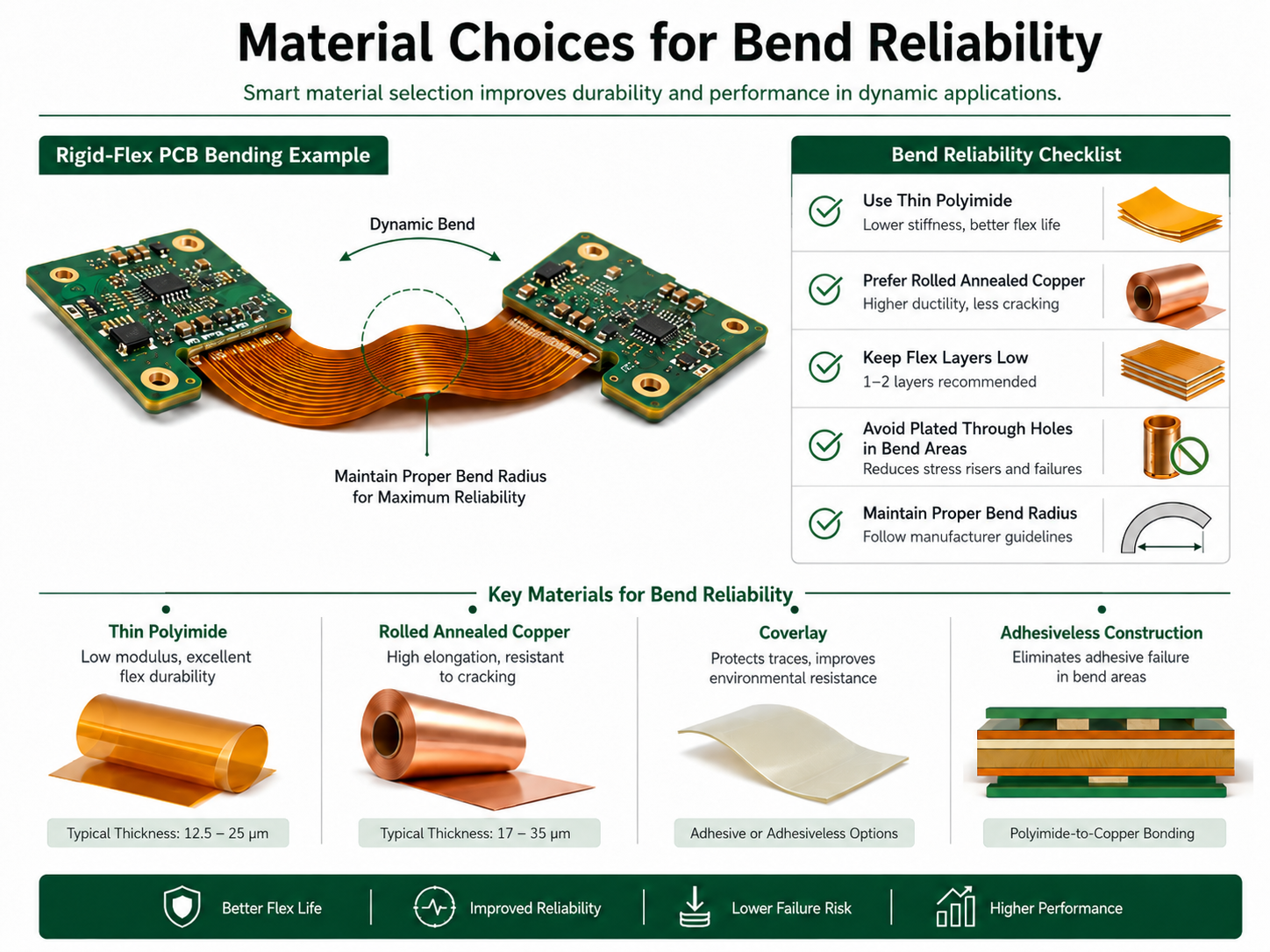
How Should Rigid-Flex PCB Materials Be Selected for Bend Reliability?
Rigid-flex PCB materials should be selected according to whether the bend is static, dynamic or bend-to-install. Static bending means the board is bent once or rarely moved. Dynamic bending means the board bends repeatedly during product use.
For dynamic bending, engineers should prioritize thin polyimide, rolled annealed copper, adhesiveless construction, proper coverlay and controlled copper layout. The flex area should avoid sharp corners, plated holes, sudden width changes and unnecessary copper density.
For better bend reliability, flex layers are often kept to one or two layers when possible. This helps reduce material thickness, lower bending stress and improve mechanical flexibility.
Material selection and layout must work together. Even excellent material can fail if the bend radius is too small, copper traces cross the bend incorrectly or the transition area is poorly designed.
How Do Rigid-Flex PCB Materials Affect Signal Integrity?
Rigid-flex PCB materials affect signal integrity through dielectric constant, dielectric thickness, copper roughness, trace geometry and layer transition design. For high-speed signals, uncontrolled material changes between rigid and flex areas can create impedance mismatch.
Polyimide usually has different electrical properties from FR4 or high-frequency rigid laminates. This means the stack-up must be reviewed carefully when controlled impedance is required.
For RF, antenna, camera module, high-speed data or medical signal applications, engineers should confirm Dk, Df, copper type, trace width, spacing, reference plane continuity and bend area routing. Material datasheets alone are not enough; the actual stack-up must be calculated and verified.
What Are Common Rigid-Flex PCB Material Failures?
Common material-related failures include copper cracking, coverlay separation, delamination, resin recession, rigid-flex transition cracking, solder joint fatigue, insulation failure and impedance drift. Many of these failures start from poor material matching or weak stack-up design.
Copper cracking often happens when copper is too thick, bend radius is too tight or trace direction is poorly arranged. Delamination may occur when adhesive systems, lamination settings or thermal cycling conditions are not properly controlled.
The rigid-flex transition area is especially important. This area connects a stiff rigid structure to a flexible structure, so stress can concentrate there. Material thickness, coverlay extension, copper layout and mechanical support must be designed carefully.
What Standards Apply to Rigid-Flex PCB Materials?
The most commonly referenced design standard is IPC-2223, which covers flexible and rigid-flex printed board design. Manufacturers and engineers may also refer to related IPC performance and qualification standards for flexible printed circuits.
IPC-related rigid-flex guidance is important because it helps define material use, stack-up design, bend reliability, coverlay rules and testing expectations. These standards help reduce design ambiguity between customers, PCB engineers and manufacturers.
For commercial projects, buyers may also request RoHS, REACH, UL, ISO quality management, halogen-free material or automotive reliability documentation depending on the final market.
Where Are Rigid-Flex PCB Materials Used?
Rigid-flex PCB materials are used in electronic products that require compact assembly, folding structure, lightweight design and reliable interconnection. Common industries include medical electronics, aerospace, automotive, industrial control, robotics, consumer electronics, wearables and communication devices.
Typical applications include camera modules, surgical tools, hearing aids, wearable sensors, automotive control modules, UAV electronics, display modules, foldable devices, test equipment and compact power systems.
Rigid-flex boards are especially useful when connectors and wire harnesses create space, weight or reliability problems. By replacing separate cables and connectors, rigid-flex PCB materials can help simplify assembly and reduce failure points.
How Do Rigid-Flex PCB Materials Affect Cost?
Rigid-flex PCB materials affect cost through material grade, layer count, flex layer number, copper thickness, coverlay type, adhesive type, rigid laminate type, controlled impedance needs and testing requirements.
Adhesiveless materials, high-Tg laminates, polyimide rigid laminates, low-loss materials and dynamic-flex structures usually cost more. However, they may reduce connector cost, assembly labor, field failure and product size.
Cost should be evaluated at the product level. A rigid-flex PCB may have a higher board price than a separate rigid PCB and flex cable, but it can reduce assembly steps, connector quantity, internal space and long-term reliability risk.
How Can Buyers Choose a Rigid-Flex PCB Materials Supplier?
Buyers should choose a supplier that understands both rigid PCB manufacturing and flexible circuit behavior. Rigid-flex production requires control of lamination, coverlay alignment, bend area stress, copper adhesion and dimensional stability.
A good supplier should provide material stack-up review, DFM feedback, impedance support, prototype validation, quality inspection and mass production control. The supplier should also help confirm bend radius, copper type, coverlay design and rigid-flex transition structure before production.
For OEM and ODM projects, buyers should not only compare price. They should ask whether the factory has experience with similar products, similar layer counts and similar reliability requirements.
What Should You Confirm Before Ordering Rigid-Flex PCB Materials?
Before ordering rigid-flex PCB materials, confirm the rigid laminate, flexible core material, copper type, copper thickness, adhesive or adhesiveless structure, coverlay thickness, stack-up, bend radius and surface finish.
You should also confirm whether the board is static-flex or dynamic-flex. This single detail can change the material recommendation, copper choice and bend design rules.
For production preparation, provide Gerber files, stack-up requirements, assembly drawing, bend direction, bend radius, component height limits, impedance needs and final application environment. This helps the manufacturer identify risks before tooling and lamination.
FAQs About Rigid-Flex PCB Materials
Q1: What are the most common Rigid-Flex PCB Materials?
A1: The most common Rigid-Flex PCB Materials include polyimide film, copper foil, FR4 laminate, high-Tg FR4, prepreg, adhesive, coverlay, flexible solder mask and stiffener materials. Polyimide is used in the flexible area, while FR4 or high-Tg laminate is often used in the rigid area.
Q2: Why is polyimide used in rigid-flex PCB materials?
A2: Polyimide is used because it provides strong heat resistance, flexibility and dimensional stability. It can survive soldering temperature and repeated bending better than many organic materials. This makes it suitable for flexible sections in medical devices, automotive modules, aerospace products and compact electronics.
Q3: Is adhesiveless material better for rigid-flex PCB?
A3: Adhesiveless material is often better for thin, high-reliability or dynamic-flex designs because it removes one adhesive interface and can improve bending performance. However, it costs more than adhesive-based material. For static flex or bend-to-install products, adhesive-based materials may still be practical and cost-effective.
Q4: What copper is best for flexible areas?
A4: Rolled annealed copper is usually preferred for flexible areas that need repeated bending because it has better fatigue resistance. Electrodeposited copper can be suitable for static bend or standard applications. The best choice depends on flex cycle requirement, copper thickness, bend radius and current load.
Q5: What is coverlay in rigid-flex PCB materials?
A5: Coverlay is a protective polyimide-based layer used over copper traces in the flexible area. Common coverlay materials may use 12.5–50 μm polyimide film and 12.5–25 μm adhesive. It protects the circuit from abrasion, moisture and electrical shorting, especially in bend areas.
Q6: Can rigid-flex PCB materials support controlled impedance?
A6: Yes, rigid-flex PCB materials can support controlled impedance, but the stack-up must be carefully designed. Engineers should control Dk, Df, trace width, dielectric thickness, copper roughness and reference plane continuity. This is especially important for RF, camera, antenna and high-speed data applications.
Q7: What causes rigid-flex PCB material failure?
A7: Common causes include tight bend radius, thick copper in bend areas, poor coverlay design, weak lamination, incorrect adhesive selection and stress concentration at the rigid-flex transition. Failures may appear as copper cracking, delamination, coverlay lifting, insulation problems or solder joint fatigue.
Q8: Are rigid-flex PCB materials expensive?
A8: Rigid-flex PCB materials are usually more expensive than standard rigid PCB materials because they combine rigid and flexible structures. Cost increases with layer count, flex layer number, adhesiveless material, controlled impedance and reliability testing. However, they can reduce connectors, labor and field failure risk.
Q9: What standards are used for rigid-flex PCB design?
A9: IPC-2223 is commonly referenced for flexible and rigid-flex printed board design. Depending on the product, buyers may also request IPC performance standards, RoHS, REACH, UL, ISO quality control or automotive reliability documentation. Standards help improve design consistency and production quality.
Q10: How do I choose materials for dynamic-flex applications?
A10: For dynamic-flex applications, choose thin polyimide, rolled annealed copper, suitable coverlay and preferably adhesiveless flexible copper-clad laminate. Keep the flex layer count low, often one or two layers when possible, avoid vias in bend areas and maintain a proper bend radius.
Q11: Can FR4 be used in rigid-flex PCB materials?
A11: Yes, FR4 is commonly used in the rigid sections of rigid-flex PCBs. For higher temperature or reliability needs, high-Tg FR4 or polyimide laminate may be selected. The flexible section usually uses polyimide, so the full stack-up must be reviewed for lamination compatibility and reliability.
Q12: What should buyers ask before ordering rigid-flex PCB materials?
A12: Buyers should ask about stack-up, flexible core material, copper type, coverlay thickness, bend radius, adhesive or adhesiveless construction, surface finish and testing plan. They should also confirm whether the supplier has experience with similar rigid-flex structures and can provide DFM support before production.
Conclusion
Rigid-Flex PCB Materials should be selected by matching the product’s mechanical movement, thermal condition, electrical requirement and assembly structure. Polyimide, copper foil, coverlay, adhesive system, rigid laminate and prepreg all affect the final reliability of the board.
For stable projects, focus on bend type, copper selection, stack-up balance, coverlay design, rigid-flex transition control and supplier capability. For procurement, the best choice is not always the lowest quote, but the material system that can support prototype validation, mass production and long-term product reliability.
You may also like
Tags: PCB Material, Rigid-flex PCB, Rigid-Flex PCB Materials